EP3098385A1 - Casting of turbine blades - Google Patents
Casting of turbine blades Download PDFInfo
- Publication number
- EP3098385A1 EP3098385A1 EP16167125.0A EP16167125A EP3098385A1 EP 3098385 A1 EP3098385 A1 EP 3098385A1 EP 16167125 A EP16167125 A EP 16167125A EP 3098385 A1 EP3098385 A1 EP 3098385A1
- Authority
- EP
- European Patent Office
- Prior art keywords
- pedestals
- core
- tip end
- single row
- holes
- Prior art date
- Legal status (The legal status is an assumption and is not a legal conclusion. Google has not performed a legal analysis and makes no representation as to the accuracy of the status listed.)
- Withdrawn
Links
Images






Classifications
-
- F—MECHANICAL ENGINEERING; LIGHTING; HEATING; WEAPONS; BLASTING
- F01—MACHINES OR ENGINES IN GENERAL; ENGINE PLANTS IN GENERAL; STEAM ENGINES
- F01D—NON-POSITIVE DISPLACEMENT MACHINES OR ENGINES, e.g. STEAM TURBINES
- F01D5/00—Blades; Blade-carrying members; Heating, heat-insulating, cooling or antivibration means on the blades or the members
- F01D5/12—Blades
- F01D5/14—Form or construction
- F01D5/18—Hollow blades, i.e. blades with cooling or heating channels or cavities; Heating, heat-insulating or cooling means on blades
- F01D5/187—Convection cooling
-
- B—PERFORMING OPERATIONS; TRANSPORTING
- B22—CASTING; POWDER METALLURGY
- B22C—FOUNDRY MOULDING
- B22C9/00—Moulds or cores; Moulding processes
- B22C9/10—Cores; Manufacture or installation of cores
-
- B—PERFORMING OPERATIONS; TRANSPORTING
- B22—CASTING; POWDER METALLURGY
- B22C—FOUNDRY MOULDING
- B22C9/00—Moulds or cores; Moulding processes
- B22C9/10—Cores; Manufacture or installation of cores
- B22C9/101—Permanent cores
-
- B—PERFORMING OPERATIONS; TRANSPORTING
- B22—CASTING; POWDER METALLURGY
- B22C—FOUNDRY MOULDING
- B22C9/00—Moulds or cores; Moulding processes
- B22C9/22—Moulds for peculiarly-shaped castings
- B22C9/24—Moulds for peculiarly-shaped castings for hollow articles
-
- B—PERFORMING OPERATIONS; TRANSPORTING
- B22—CASTING; POWDER METALLURGY
- B22D—CASTING OF METALS; CASTING OF OTHER SUBSTANCES BY THE SAME PROCESSES OR DEVICES
- B22D25/00—Special casting characterised by the nature of the product
- B22D25/02—Special casting characterised by the nature of the product by its peculiarity of shape; of works of art
-
- B—PERFORMING OPERATIONS; TRANSPORTING
- B22—CASTING; POWDER METALLURGY
- B22D—CASTING OF METALS; CASTING OF OTHER SUBSTANCES BY THE SAME PROCESSES OR DEVICES
- B22D29/00—Removing castings from moulds, not restricted to casting processes covered by a single main group; Removing cores; Handling ingots
- B22D29/001—Removing cores
-
- B—PERFORMING OPERATIONS; TRANSPORTING
- B22—CASTING; POWDER METALLURGY
- B22D—CASTING OF METALS; CASTING OF OTHER SUBSTANCES BY THE SAME PROCESSES OR DEVICES
- B22D30/00—Cooling castings, not restricted to casting processes covered by a single main group
-
- F—MECHANICAL ENGINEERING; LIGHTING; HEATING; WEAPONS; BLASTING
- F01—MACHINES OR ENGINES IN GENERAL; ENGINE PLANTS IN GENERAL; STEAM ENGINES
- F01D—NON-POSITIVE DISPLACEMENT MACHINES OR ENGINES, e.g. STEAM TURBINES
- F01D5/00—Blades; Blade-carrying members; Heating, heat-insulating, cooling or antivibration means on the blades or the members
- F01D5/12—Blades
- F01D5/14—Form or construction
- F01D5/18—Hollow blades, i.e. blades with cooling or heating channels or cavities; Heating, heat-insulating or cooling means on blades
- F01D5/186—Film cooling
-
- F—MECHANICAL ENGINEERING; LIGHTING; HEATING; WEAPONS; BLASTING
- F05—INDEXING SCHEMES RELATING TO ENGINES OR PUMPS IN VARIOUS SUBCLASSES OF CLASSES F01-F04
- F05D—INDEXING SCHEME FOR ASPECTS RELATING TO NON-POSITIVE-DISPLACEMENT MACHINES OR ENGINES, GAS-TURBINES OR JET-PROPULSION PLANTS
- F05D2220/00—Application
- F05D2220/30—Application in turbines
- F05D2220/32—Application in turbines in gas turbines
-
- F—MECHANICAL ENGINEERING; LIGHTING; HEATING; WEAPONS; BLASTING
- F05—INDEXING SCHEMES RELATING TO ENGINES OR PUMPS IN VARIOUS SUBCLASSES OF CLASSES F01-F04
- F05D—INDEXING SCHEME FOR ASPECTS RELATING TO NON-POSITIVE-DISPLACEMENT MACHINES OR ENGINES, GAS-TURBINES OR JET-PROPULSION PLANTS
- F05D2230/00—Manufacture
- F05D2230/20—Manufacture essentially without removing material
- F05D2230/21—Manufacture essentially without removing material by casting
-
- F—MECHANICAL ENGINEERING; LIGHTING; HEATING; WEAPONS; BLASTING
- F05—INDEXING SCHEMES RELATING TO ENGINES OR PUMPS IN VARIOUS SUBCLASSES OF CLASSES F01-F04
- F05D—INDEXING SCHEME FOR ASPECTS RELATING TO NON-POSITIVE-DISPLACEMENT MACHINES OR ENGINES, GAS-TURBINES OR JET-PROPULSION PLANTS
- F05D2230/00—Manufacture
- F05D2230/20—Manufacture essentially without removing material
- F05D2230/21—Manufacture essentially without removing material by casting
- F05D2230/211—Manufacture essentially without removing material by casting by precision casting, e.g. microfusing or investment casting
Definitions
- the present disclosure concerns the cooling of turbine blades. More particularly, the invention concerns the positioning of cooling holes in a turbine blade for use in a gas turbine engine.
- ambient air is drawn into a compressor section.
- Alternate rows of stationary and rotating aerofoil blades are arranged around a common axis, together these accelerate and compress the incoming air.
- a rotating shaft drives the rotating blades.
- Compressed air is delivered to a combustor section where it is mixed with fuel and ignited. Ignition causes rapid expansion of the fuel/air mix which is directed in part to propel a body carrying the engine and in another part to drive rotation of a series of turbines arranged downstream of the combustor.
- the turbines share rotor shafts in common with the rotating blades of the compressor and work, through the shaft, to drive rotation of the compressor blades.
- cooling air is delivered adjacent the rim of the turbine disc and directed to a port which enters the turbine blade body and is distributed through the blade, typically by means of a labyrinth of channels extending through the blade body. Cooling of blade surfaces is aided by impingement cooling wherein small cooling holes extend from the channels through internal walls of the blade body and cause jets of air to impinge on the appropriate surfaces. For example (but without limitation) impingement cooling is often used to cool the leading edge passages of an aerofoil.
- Turbine blades are known to be manufactured by casting methods.
- a mould defines an external geometry of the turbine and a core is inserted into the mould to define the internal geometry, molten material (typically a ferrous or nonferrous alloy) is then cast between the mould and the core and the core subsequently is removed, for example by leaching.
- the core can include arrays of pedestals which define the arrangement of cooling holes in surfaces of the turbine blade.
- Arrays of holes are designed to provide optimum cooling of a surface.
- Existing designs feature single rows of holes (an example is disclosed in US 2009/0317258 ); staggered rows and grid formations.
- Radial stresses in a blade body are mainly driven by centripetal loads caused by blade rotation. From the perspective of blade design, to minimise stresses in the impingement holes it is advantageous to employ a single row of holes aligned with the radial stress field in the impingement web.
- a method for casting a turbine blade body comprising; providing a mould defining the external geometry of the blade body; providing a core defining an internal geometry of the blade body, the core comprising a main body defining an internal chamber of the blade body and having a root end and a tip end and a plurality of pedestals defining an array of cooling channels extending from the internal chamber; casting a molten material between the mould and the core; and removing the core after the molten material has solidified, wherein the pedestals are arranged in a single row starting from the root end of the main body branching into multiple rows which extend towards the tip end of the body.
- the branching may occur at any position in the mid-portion between the root and tip, for example, a branch may occur closer to the root end. In some embodiments, the branch may occur between about 20% and 80% of the distance between the root and tip ends, for example between 30% and 70%. Optimal positions for branching may vary with blade geometry and the anticipated working environment for the blade body.
- the multiple rows diverge from each other adjacent the branch. Divergent rows may turn back to a parallel configuration as they approach the tip end. Alternatively, branched rows may diverge continuously towards the tip end.
- the present invention provides blade body designs which are optimised to both limit impingement stresses in the holes and enable manufacture using a core which has a reduced susceptibility to fail due to adverse bending moments arising in the molten phase of the casting process.
- the number of branches is conveniently two.
- the arrangement of pedestals branches into a pair of rows arranged symmetrically about a centreline which passes through the single row.
- branched rows are arranged asymmetrically about a centreline which passes through the single row.
- the pedestals may all have the same cross sectional area.
- one or more of the pedestals may have a larger cross sectional area than the remaining pedestals.
- Pedestals of larger cross sectional area may be biasedly located towards the tip end of the core.
- the cross sectional area of the pedestals may gradually increase from the root end to the tip end of the arrangement. In some examples of such embodiments, some or all of the pedestals may be grouped into numbers of pedestals with equal cross sectional areas.
- pedestals of larger cross sectional area are randomly dispersed between pedestals of relatively smaller cross section.
- a pedestal of larger cross section than the others is positioned at each of the root and tip end of the pedestal arrangement.
- the invention optimises the arrangement of holes to satisfy both stress and manufacturing requirements.
- the lower portion (root end) of holes is in a single row which is optimal for the stress shielding effect.
- a stagger can be slowly introduced. This enables provision of improved bending stiffness of the pedestal array towards the tip end of the core to reduce core breakage risk during casting.
- the pedestals may have any practical cross-sectional shape.
- the cross-sectional shape is circular, elliptical or racetrack.
- the cross-sectional shape does not include tight radii.
- the pedestals may be inclined with respect to a surface of the main core body resulting in inclined cooling channels in the walls of the cast component.
- a gas turbine engine is generally indicated at 10, having a principal and rotational axis 11.
- the engine 10 comprises, in axial flow series, an air intake 12, a propulsive fan 13, a high-pressure compressor 14, combustion equipment 15, a high-pressure turbine 16, a low-pressure turbine 17 and an exhaust nozzle 18.
- a nacelle 20 generally surrounds the engine 10 and defines the intake 12.
- the gas turbine engine 10 works in the conventional manner so that air entering the intake 12 is accelerated by the fan 13 to produce two air flows: a first air flow into the high-pressure compressor 14 and a second air flow which passes through a bypass duct 21 to provide propulsive thrust.
- the high-pressure compressor 14 compresses the air flow directed into it before delivering that air to the combustion equipment 15.
- the air flow is mixed with fuel and the mixture combusted.
- the resultant hot combustion products then expand through, and thereby drive the high and low-pressure turbines 16, 17 before being exhausted through the nozzle 18 to provide additional propulsive thrust.
- the high 16 and low 17 pressure turbines drive respectively the high pressure compressor 14 and the fan 13, each by suitable interconnecting shaft.
- gas turbine engines to which the present disclosure may be applied may have alternative configurations.
- such engines may have an alternative number of interconnecting shafts (e.g. three) and/or an alternative number of compressors and/or turbines.
- the engine may comprise a gearbox provided in the drive train from a turbine to a compressor and/or fan.
- the blades of turbines 16 and 17 are subjected to extremes of temperature by hot gases expelled from the combustion equipment 15. Relatively cool air from the compressor 14 is taken off upstream of the combustion equipment and directed to the blades for use as a cooling fluid.
- the blades can be provided with multiple internal channels and arrays of cooling channels in surfaces affected by the heat.
- the blades can be manufactured using methods in accordance with the invention.
- Figures 2a, 2b and 2c show arrays of cooling holes known to be provided in turbine blades of the prior art, for example along the leading edge of the blade.
- Figure 14 illustrates a prior art blade exhibiting such an array of holes. It will be appreciated that the arrays of holes are achieved using cores having pedestals arranged in similar arrays, the blade body being cast between a mould defining its external geometry and the core. As discussed above, these arrays have been chosen to be at reduced risk of cracking due to radial stress fields to which they are subjected when the turbine blade is in use.
- FIG. 2a shows a blade surface 1 having a single row 2 of equally sized, equally spaced holes.
- Figure 2b shows an array 3 of two parallel aligned rows, each row comprising equally sized, equally spaced holes.
- Figure 2c shows an array 4 of two parallel aligned rows, each row comprising equally sized, equally spaced holes, but the rows are staggered.
- Figures 3a, 3b and 3c show the stress fields experienced by the arrays 2, 3 and 4 of Figures 2a, 2b and 2c .
- Figure 3d shows a more complex stress field which results from positioning the rows of array 4 more closely together.
- Figure 4a shows the bending moments (dashed line arrow) to which a single pedestal 5 of a core 6 is subjected.
- Figure 4b shows a pair of pedestals 5a, 5b anchored in a core 6. It will be appreciated the two anchored pedestals 5a, 5b are far better placed to resist bending stresses caused by the bending moments than the single pedestal 5 of Figure 4a .
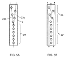
- Figure 5a shows a first array of holes achievable by a method in accordance with the invention. It will be appreciated that pedestals for creating the holes would be arranged in a similar array on a core body used to cast the blade.
- the array has two distinct sections; the first is a single row 22 of equally sized and equally spaced holes which extend from a root end to a mid-section of a blade surface 9. In the mid-section, the array branches in a Y shaped configuration providing a pair of divergent branches 23a and 23b. The holes of branches 23a and 23b are spaced further apart than in the single row 22 and are staggered with respect to one another.
- FIG. 5b illustrates the stress field for the array of Figure 5a .
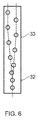
- Figure 6 shows a variant of the arrangement in Figure 5a .
- the single row 32 is shorter in length than in Figure 5a and the branched section 33 diverges more gradually.
- the example shows an arrangement optimised further towards pedestal array bending stiffness than low stresses.
- Figure 7 shows another arrangement.
- the array has two distinct sections; the first is a single row 42 of equally sized and equally spaced holes which extends from a root end to a mid-section of a blade surface 49.
- the array branches in a Y shaped configuration providing a pair of divergent branches 43.
- the holes of branches 43 are spaced similarly to those in the single row 42 and are symmetrically aligned about a centre line passing through the single row 42.
- the high density of holes in the branched portion can serve to maximise cooling performance and/or improve bending stiffness in the pedestal array.
- Figure 8 shows another arrangement.
- the arrangement is broadly similar to that of Figure 5a but differs primarily in that in a region of the single row 52 towards the root end, the size of the holes is gradually reduced. This arrangement is beneficial in minimising stresses in the lowest holes utilising the stress shielding effect.
- Figure 9 shows another arrangement.
- the arrangement is broadly similar to that of Figure 5a but differs primarily in that in a region of the branched section 63 towards the tip end, the size of holes is gradually increased. This arrangement is beneficial in maximising bending stiffness of the pedestal array and strengthening the branched section of the array.
- Figure 10 shows another arrangement.
- the arrangement is broadly similar to that of Figure 5a but differs primarily in that "anchor" holes 73a, 73b of larger diameter than the rest are positioned one adjacent the tip end and one adjacent the root end.
- the “anchor" holes provide extra stiffness and strength to the extreme ends of the pedestal array to avoid 'pedestal unzipping'.
- Figure 11 shows an arrangement broadly similar to that of Figure 10 but differs in that a first anchor hole 83a is positioned immediately adjacent the tip end and a second anchor hole 83b is positioned in a mid-section of single row 82.
- This arrangement is beneficial in providing stress shielding to the lowest hole whilst also providing some 'unzipping' protection. It provides a balance between the objectives of pedestal array bending stiffness/strength and reduced hole stress.
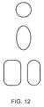
- Figure 12 shows examples of cross sectional shapes for holes and pedestals already discussed in relation to the method of the invention. Hole selection may be based on cooling/stress/manufacturing compromises.
- Figure 13 shows a wall section in a 3D perspective view illustrating a channel associated with the holes already discussed in relation to the method of the invention. It will be seen the channel 50 is inclined with respect to external surfaces of the wall. It will be appreciated that pedestals of a core used in methods of the invention can be provided at appropriate angles in order to provide such inclined channels. In the left hand image, it can be seen the channel is radially inclined. In the right hand figure, the channel is both radially and in-plane inclined.
- Figure 14 shows a turbine blade 90 as known from the prior art.
- the blade has a leading edge surface 91 into which an array of cooling channels is provided. It will be appreciated that the array shown on surface 91 can be replaced with the arrays described in the examples of the invention discussed above in a turbine blade made according to a method of the invention.
Landscapes
- Engineering & Computer Science (AREA)
- Mechanical Engineering (AREA)
- General Engineering & Computer Science (AREA)
- Turbine Rotor Nozzle Sealing (AREA)
Abstract
Description
- The present disclosure concerns the cooling of turbine blades. More particularly, the invention concerns the positioning of cooling holes in a turbine blade for use in a gas turbine engine.
- In a gas turbine engine, ambient air is drawn into a compressor section. Alternate rows of stationary and rotating aerofoil blades are arranged around a common axis, together these accelerate and compress the incoming air. A rotating shaft drives the rotating blades. Compressed air is delivered to a combustor section where it is mixed with fuel and ignited. Ignition causes rapid expansion of the fuel/air mix which is directed in part to propel a body carrying the engine and in another part to drive rotation of a series of turbines arranged downstream of the combustor. The turbines share rotor shafts in common with the rotating blades of the compressor and work, through the shaft, to drive rotation of the compressor blades.
- It is well known that the operating efficiency of a gas turbine engine is improved by increasing the operating temperature. The ability to optimise efficiency through increased temperatures is restricted by changes in behaviour of materials used in the engine components at elevated temperatures which, amongst other things, can impact upon the mechanical strength of the blades and a rotor disc which carries the blades. This problem is addressed by providing a flow of coolant through and/or over the turbine rotor disc and blades.
- It is known to take off a portion of the air output from the compressor (which is not subjected to ignition in the combustor and so is relatively cooler) and feed this to surfaces in the turbine section which are likely to suffer damage from excessive heat. Typically the cooling air is delivered adjacent the rim of the turbine disc and directed to a port which enters the turbine blade body and is distributed through the blade, typically by means of a labyrinth of channels extending through the blade body. Cooling of blade surfaces is aided by impingement cooling wherein small cooling holes extend from the channels through internal walls of the blade body and cause jets of air to impinge on the appropriate surfaces. For example (but without limitation) impingement cooling is often used to cool the leading edge passages of an aerofoil.
- Turbine blades are known to be manufactured by casting methods. A mould defines an external geometry of the turbine and a core is inserted into the mould to define the internal geometry, molten material (typically a ferrous or nonferrous alloy) is then cast between the mould and the core and the core subsequently is removed, for example by leaching. The core can include arrays of pedestals which define the arrangement of cooling holes in surfaces of the turbine blade.
- Arrays of holes are designed to provide optimum cooling of a surface. Existing designs feature single rows of holes (an example is disclosed in
US 2009/0317258 ); staggered rows and grid formations. Radial stresses in a blade body are mainly driven by centripetal loads caused by blade rotation. From the perspective of blade design, to minimise stresses in the impingement holes it is advantageous to employ a single row of holes aligned with the radial stress field in the impingement web. - According to a first aspect there is provided a method for casting a turbine blade body, the method comprising;
providing a mould defining the external geometry of the blade body;
providing a core defining an internal geometry of the blade body, the core comprising a main body defining an internal chamber of the blade body and having a root end and a tip end and a plurality of pedestals defining an array of cooling channels extending from the internal chamber;
casting a molten material between the mould and the core; and
removing the core after the molten material has solidified, wherein the pedestals are arranged in a single row starting from the root end of the main body branching into multiple rows which extend towards the tip end of the body. - The branching may occur at any position in the mid-portion between the root and tip, for example, a branch may occur closer to the root end. In some embodiments, the branch may occur between about 20% and 80% of the distance between the root and tip ends, for example between 30% and 70%. Optimal positions for branching may vary with blade geometry and the anticipated working environment for the blade body. Optionally, the multiple rows diverge from each other adjacent the branch. Divergent rows may turn back to a parallel configuration as they approach the tip end. Alternatively, branched rows may diverge continuously towards the tip end.
- Whilst desirable from a blade design perspective, from a casting perspective a single row of holes presents a potential risk. To ensure conforming geometry, it is essential that the cores around which the blade body is cast do not break during casting. During casting, significant bending moments may be applied to the pedestals by the molten alloy, for example to the leading edge passage, which may lead to breakage of the pedestals. Compared to double rows of pedestals, single rows have much less bending stiffness and are consequently more prone to breakage. Hence it is considered to be advantageous for casting to use double rows of pedestals. However, from a blade design perspective, inadequately spaced double rows of cooling holes are considerably more susceptible to complex radial stress fields and are consequently less desirable than single rows.
- The present invention provides blade body designs which are optimised to both limit impingement stresses in the holes and enable manufacture using a core which has a reduced susceptibility to fail due to adverse bending moments arising in the molten phase of the casting process.
- The number of branches is conveniently two. In one simple embodiment, the arrangement of pedestals branches into a pair of rows arranged symmetrically about a centreline which passes through the single row. In other embodiments branched rows are arranged asymmetrically about a centreline which passes through the single row.
- The pedestals may all have the same cross sectional area. Optionally, one or more of the pedestals may have a larger cross sectional area than the remaining pedestals. Pedestals of larger cross sectional area may be biasedly located towards the tip end of the core.
- In some embodiments, the cross sectional area of the pedestals may gradually increase from the root end to the tip end of the arrangement. In some examples of such embodiments, some or all of the pedestals may be grouped into numbers of pedestals with equal cross sectional areas.
- In some embodiments, pedestals of larger cross sectional area are randomly dispersed between pedestals of relatively smaller cross section.
- In some embodiments, a pedestal of larger cross section than the others is positioned at each of the root and tip end of the pedestal arrangement.
- Radial loads in blade cooling channels and holes are primarily driven by centripetal forces as a result of the blade rotation about the engine axis. Consequently, radial loads are greatest towards the root of the blade and reduce towards the tip as the amount of supported mass decreases to zero. Hence, for a cavity of uniform thickness, the most highly stressed impingement holes (cooling channels) will be located at the most inboard location and the lowest stressed holes will be at the most outboard location.
- The invention optimises the arrangement of holes to satisfy both stress and manufacturing requirements. The lower portion (root end) of holes is in a single row which is optimal for the stress shielding effect. As radial loads reduce moving outboard, a stagger can be slowly introduced. This enables provision of improved bending stiffness of the pedestal array towards the tip end of the core to reduce core breakage risk during casting.
- By arranging the pedestals/holes as per the invention, stresses in the highest risk holes can be reduced in the blade body whilst maintaining bending stiffness in a large portion of the core, reducing the risk of core breakage during casting. This avoids prior known means of reducing hole stresses such as increasing web thickness, which will lead to additional blade mass. This is unfavourable due to the downstream impacts on the turbine sub-system.
- The pedestals (and hence the holes in the blade body) may have any practical cross-sectional shape. For example (but without limitation) the cross-sectional shape is circular, elliptical or racetrack. Preferably the cross-sectional shape does not include tight radii. The pedestals may be inclined with respect to a surface of the main core body resulting in inclined cooling channels in the walls of the cast component.
- The skilled person will appreciate that except where mutually exclusive, a feature described in relation to any one of the above aspects may be applied mutatis mutandis to any other aspect. Furthermore except where mutually exclusive any feature described herein may be applied to any aspect and/or combined with any other feature described herein.
- Embodiments will now be described by way of example only, with reference to the Figures, in which:
-
Figure 1 is a sectional side view of a gas turbine engine; -
Figure 2a shows a first array of holes known to be used in turbine blades of the prior art; -
Figure 2b shows a second array of holes known to be used in turbine blades of the prior art; -
Figure 2c shows a third array of holes known to be used in turbine blades of the prior art; -
Figure 3a shows a radial stress field experienced by a first array of holes known to be used in turbine blades of the prior art; -
Figure 3b shows a radial stress field experienced by a second array of holes known to be used in turbine blades of the prior art; -
Figure 3c shows a radial stress field experienced by a third array of holes known to be used in turbine blades of the prior art; -
Figure 3d shows a radial stress field experienced by a fourth array of holes known to be used in turbine blades of the prior art; -
Figure 4a shows a single pedestal of a core and illustrates the bending moment experienced by the pedestal during the molten phase of casting; -
Figure 4b shows a two row pedestal arrangement of a core; -
Figure 5a shows a first embodiment of an array of holes in a turbine blade made in accordance with a method of the invention; -
Figure 5b shows the radial stress field experienced by the array offigure 5a ; -
Figure 6 shows a second embodiment of an array of holes in a turbine blade made in accordance with a method of the invention; -
Figure 7 shows a third embodiment of an array of holes in a turbine blade made in accordance with a method of the invention; -
Figure 8 shows a fourth embodiment of an array of holes in a turbine blade made in accordance with a method of the invention; -
Figure 9 shows a fifth embodiment of an array of holes in a turbine blade made in accordance with a method of the invention; -
Figure 10 shows a sixth embodiment of an array of holes in a turbine blade made in accordance with a method of the invention; -
Figure 11 shows a seventh embodiment of an array of holes in a turbine blade made in accordance with a method of the invention; -
Figure 12 shows some example cross-sectional shapes for pedestals/holes of the present invention; -
Figure 13 shows examples of how pedestals/holes of the invention may be inclined with respect to a planar surface; -
Figure 14 illustrates a turbine blade body including a leading edge through which cooling channels can be provided in accordance with methods of the present invention. - With reference to
Figure 1 , a gas turbine engine is generally indicated at 10, having a principal androtational axis 11. The engine 10 comprises, in axial flow series, anair intake 12, apropulsive fan 13, a high-pressure compressor 14,combustion equipment 15, a high-pressure turbine 16, a low-pressure turbine 17 and anexhaust nozzle 18. Anacelle 20 generally surrounds the engine 10 and defines theintake 12. - The gas turbine engine 10 works in the conventional manner so that air entering the
intake 12 is accelerated by thefan 13 to produce two air flows: a first air flow into the high-pressure compressor 14 and a second air flow which passes through abypass duct 21 to provide propulsive thrust. The high-pressure compressor 14 compresses the air flow directed into it before delivering that air to thecombustion equipment 15. - In the
combustion equipment 15 the air flow is mixed with fuel and the mixture combusted. The resultant hot combustion products then expand through, and thereby drive the high and low-pressure turbines 16, 17 before being exhausted through thenozzle 18 to provide additional propulsive thrust. The high 16 and low 17 pressure turbines drive respectively thehigh pressure compressor 14 and thefan 13, each by suitable interconnecting shaft. - Other gas turbine engines to which the present disclosure may be applied may have alternative configurations. By way of example such engines may have an alternative number of interconnecting shafts (e.g. three) and/or an alternative number of compressors and/or turbines. Further the engine may comprise a gearbox provided in the drive train from a turbine to a compressor and/or fan.
- The blades of
turbines 16 and 17 are subjected to extremes of temperature by hot gases expelled from thecombustion equipment 15. Relatively cool air from thecompressor 14 is taken off upstream of the combustion equipment and directed to the blades for use as a cooling fluid. The blades can be provided with multiple internal channels and arrays of cooling channels in surfaces affected by the heat. The blades can be manufactured using methods in accordance with the invention. -
Figures 2a, 2b and 2c show arrays of cooling holes known to be provided in turbine blades of the prior art, for example along the leading edge of the blade.Figure 14 illustrates a prior art blade exhibiting such an array of holes. It will be appreciated that the arrays of holes are achieved using cores having pedestals arranged in similar arrays, the blade body being cast between a mould defining its external geometry and the core. As discussed above, these arrays have been chosen to be at reduced risk of cracking due to radial stress fields to which they are subjected when the turbine blade is in use. Complex stress fields with a predominant radial component are avoided by providing the single row of holes substantially in line with the stress field and, where more than one row is present, separating the rows by sufficient distance that the stress fields experienced by each row do not interfere with each other to create a more complex stress field.Figure 2a shows a blade surface 1 having asingle row 2 of equally sized, equally spaced holes.Figure 2b shows anarray 3 of two parallel aligned rows, each row comprising equally sized, equally spaced holes.Figure 2c shows anarray 4 of two parallel aligned rows, each row comprising equally sized, equally spaced holes, but the rows are staggered. -
Figures 3a, 3b and 3c show the stress fields experienced by thearrays Figures 2a, 2b and 2c .Figure 3d shows a more complex stress field which results from positioning the rows ofarray 4 more closely together. -
Figure 4a shows the bending moments (dashed line arrow) to which asingle pedestal 5 of acore 6 is subjected.Figure 4b shows a pair ofpedestals core 6. It will be appreciated the two anchoredpedestals single pedestal 5 ofFigure 4a . -
Figure 5a shows a first array of holes achievable by a method in accordance with the invention. It will be appreciated that pedestals for creating the holes would be arranged in a similar array on a core body used to cast the blade. The array has two distinct sections; the first is asingle row 22 of equally sized and equally spaced holes which extend from a root end to a mid-section of ablade surface 9. In the mid-section, the array branches in a Y shaped configuration providing a pair ofdivergent branches branches single row 22 and are staggered with respect to one another. - The single row adjacent the root end provides maximum stress shielding for the holes in the blade surface, whilst the branched section of the array provides for improved bending stiffness of the pedestal array in the core.
Figure 5b illustrates the stress field for the array ofFigure 5a . As can be seen, there is a smooth stress field for the single row ofholes 22 where the load is highest and a more complex stress field in the mid-section to tip area where the load is lower, however the benefit of a greater bending stiffness in the pedestal array of the core provides a reduced risk of core damage and consequent component rejection during the molten phase of the casting process. -
Figure 6 shows a variant of the arrangement inFigure 5a . As can be seen thesingle row 32 is shorter in length than inFigure 5a and the branchedsection 33 diverges more gradually. The example shows an arrangement optimised further towards pedestal array bending stiffness than low stresses.
Figure 7 shows another arrangement. The array has two distinct sections; the first is asingle row 42 of equally sized and equally spaced holes which extends from a root end to a mid-section of ablade surface 49. In the mid-section, the array branches in a Y shaped configuration providing a pair ofdivergent branches 43. The holes ofbranches 43 are spaced similarly to those in thesingle row 42 and are symmetrically aligned about a centre line passing through thesingle row 42. The high density of holes in the branched portion can serve to maximise cooling performance and/or improve bending stiffness in the pedestal array. -
Figure 8 shows another arrangement. The arrangement is broadly similar to that ofFigure 5a but differs primarily in that in a region of thesingle row 52 towards the root end, the size of the holes is gradually reduced. This arrangement is beneficial in minimising stresses in the lowest holes utilising the stress shielding effect. -
Figure 9 shows another arrangement. The arrangement is broadly similar to that ofFigure 5a but differs primarily in that in a region of the branchedsection 63 towards the tip end, the size of holes is gradually increased. This arrangement is beneficial in maximising bending stiffness of the pedestal array and strengthening the branched section of the array. -
Figure 10 shows another arrangement. The arrangement is broadly similar to that ofFigure 5a but differs primarily in that "anchor"holes -
Figure 11 shows an arrangement broadly similar to that ofFigure 10 but differs in that afirst anchor hole 83a is positioned immediately adjacent the tip end and asecond anchor hole 83b is positioned in a mid-section ofsingle row 82. This arrangement is beneficial in providing stress shielding to the lowest hole whilst also providing some 'unzipping' protection. It provides a balance between the objectives of pedestal array bending stiffness/strength and reduced hole stress.Figure 12 shows examples of cross sectional shapes for holes and pedestals already discussed in relation to the method of the invention. Hole selection may be based on cooling/stress/manufacturing compromises. -
Figure 13 shows a wall section in a 3D perspective view illustrating a channel associated with the holes already discussed in relation to the method of the invention. It will be seen thechannel 50 is inclined with respect to external surfaces of the wall. It will be appreciated that pedestals of a core used in methods of the invention can be provided at appropriate angles in order to provide such inclined channels. In the left hand image, it can be seen the channel is radially inclined. In the right hand figure, the channel is both radially and in-plane inclined. -
Figure 14 shows aturbine blade 90 as known from the prior art. The blade has aleading edge surface 91 into which an array of cooling channels is provided. It will be appreciated that the array shown onsurface 91 can be replaced with the arrays described in the examples of the invention discussed above in a turbine blade made according to a method of the invention. - It will be understood that the invention is not limited to the embodiments above-described and various modifications and improvements can be made without departing from the concepts described herein. Except where mutually exclusive, any of the features may be employed separately or in combination with any other features and the disclosure extends to and includes all combinations and subcombinations of one or more features described herein.
Claims (16)
- A method for casting a turbine blade body, the method comprising;
providing a mould defining the external geometry of the blade body;
providing a core defining an internal geometry of the blade body, the core comprising a main body defining an internal chamber of the blade body and having a root end and a tip end and a plurality of pedestals defining an array of cooling channels extending from the internal chamber;
casting a molten material between the mould and the core; and
removing the core after the molten material has solidified,
wherein the pedestals are arranged in a single row (22) starting from the root end to of the main body (9) branching into multiple rows (23a, 23b) towards the tip end of the body (9). - A method as claimed in claim 1 wherein the number of branches is two.
- A method as claimed in claim 2 wherein the arrangement of pedestals branches into a pair of rows (43) arranged symmetrically about a centreline which passes through the single row (44).
- A method as claimed in claim 2 wherein the arrangement of pedestals branches into a pair of rows (23a, 23b) arranged asymmetrically about a centreline which passes through the single row (22).
- A method as claimed in any preceding claim wherein the pedestals all have the same cross sectional area.
- A method as claimed in claim 1 to 4 wherein one or more of the pedestals (73a;73b;83a;83b) has a larger cross sectional area than the remaining pedestals.
- A method as claimed in claim 6 wherein a pedestal of larger cross sectional area (73a; 83a) is positioned at or near the tip end of the core body.
- A method as claimed in claim 6 or 7 wherein a pedestal (73b; 83b) of larger cross sectional area is positioned at or near the root end of the core body.
- A method as claimed in any of claims 1 to 7 wherein the cross sectional area of pedestals gradually increases from the root end to the tip end of the arrangement.
- A method as claimed in claim 9 wherein some or all of the pedestals are grouped into numbers of pedestals with equal cross sectional areas.
- A method as claimed in any preceding claim wherein the pedestals have a cross-sectional shape selected from; circular, elliptical or race track.
- A method as claimed in any preceding claim wherein the pedestals are inclined to a surface of the main body and the resulting blade body includes channels (50) which are inclined to surfaces of walls of the blade body.
- A method as claimed in any preceding claim wherein the single row branches at a position which is closer to the root end than to the tip end.
- A method as claimed in any preceding claim wherein the single row branches at a position in the range from 20% to 80% of the distance from the root end to the tip end.
- A method as claimed in claim 14 wherein the single row branches at a position in the range from 30% to 70% of the distance from the root end to the tip end.
- A method as claimed in any preceding claim wherein the multiple rows diverge from the branch position for at least part of the distance to the tip end.
Applications Claiming Priority (1)
| Application Number | Priority Date | Filing Date | Title |
|---|---|---|---|
| GBGB1508795.0A GB201508795D0 (en) | 2015-05-22 | 2015-05-22 | Cooling of turbine blades |
Publications (1)
| Publication Number | Publication Date |
|---|---|
| EP3098385A1 true EP3098385A1 (en) | 2016-11-30 |
Family
ID=53506177
Family Applications (1)
| Application Number | Title | Priority Date | Filing Date |
|---|---|---|---|
| EP16167125.0A Withdrawn EP3098385A1 (en) | 2015-05-22 | 2016-04-26 | Casting of turbine blades |
Country Status (3)
| Country | Link |
|---|---|
| US (1) | US9719358B2 (en) |
| EP (1) | EP3098385A1 (en) |
| GB (1) | GB201508795D0 (en) |
Cited By (2)
| Publication number | Priority date | Publication date | Assignee | Title |
|---|---|---|---|---|
| EP3467267A1 (en) * | 2017-10-03 | 2019-04-10 | United Technologies Corporation | Airfoil for a gas turbine engine and corresponding core strucuture for manufacturing an airfoil |
| US11939882B2 (en) | 2019-01-17 | 2024-03-26 | Mitsubishi Heavy Industries, Ltd. | Turbine rotor blade and gas turbine |
Families Citing this family (7)
| Publication number | Priority date | Publication date | Assignee | Title |
|---|---|---|---|---|
| BR112015002552A2 (en) * | 2012-08-06 | 2018-05-22 | Gen Electric | turbine airfoil and method of producing a turbine airfoil |
| US10358940B2 (en) | 2017-06-26 | 2019-07-23 | United Technologies Corporation | Elliptical slot with shielding holes |
| CN107506519B (en) * | 2017-07-07 | 2020-07-03 | 厦门大学 | Parametric machining method for gas film cooling hole of precision-cast turbine blade |
| US10788053B2 (en) | 2018-10-25 | 2020-09-29 | General Electric Company | Noise reducing gas turbine engine airfoil |
| US11761632B2 (en) * | 2021-08-05 | 2023-09-19 | General Electric Company | Combustor swirler with vanes incorporating open area |
| GB202310234D0 (en) * | 2023-07-04 | 2023-08-16 | Rolls Royce Plc | Gas turbine engine component with variable cooling hole geometry |
| CN118795838B (en) * | 2024-09-14 | 2024-11-15 | 中国航发北京航空材料研究院 | A method and system for adjusting grinding allowance of turbine guide blades |
Citations (4)
| Publication number | Priority date | Publication date | Assignee | Title |
|---|---|---|---|---|
| EP1258597A2 (en) * | 2001-05-17 | 2002-11-20 | General Electric Company | Gas turbine engine blade |
| EP1288436A2 (en) * | 2001-08-30 | 2003-03-05 | General Electric Company | Turbine airfoil for gas turbine engine |
| EP1759788A2 (en) * | 2005-09-01 | 2007-03-07 | United Technologies Corporation | Investment casting of cooled turbine airfoils |
| US20130230402A1 (en) * | 2012-03-02 | 2013-09-05 | United Technologies Corporation | Tapered thermal coating for airfoil |
Family Cites Families (7)
| Publication number | Priority date | Publication date | Assignee | Title |
|---|---|---|---|---|
| US6243948B1 (en) * | 1999-11-18 | 2001-06-12 | General Electric Company | Modification and repair of film cooling holes in gas turbine engine components |
| US6668906B2 (en) * | 2002-04-29 | 2003-12-30 | United Technologies Corporation | Shaped core for cast cooling passages and enhanced part definition |
| US7008186B2 (en) * | 2003-09-17 | 2006-03-07 | General Electric Company | Teardrop film cooled blade |
| US7172012B1 (en) * | 2004-07-14 | 2007-02-06 | United Technologies Corporation | Investment casting |
| US7249934B2 (en) * | 2005-08-31 | 2007-07-31 | General Electric Company | Pattern cooled turbine airfoil |
| GB0811391D0 (en) | 2008-06-23 | 2008-07-30 | Rolls Royce Plc | A rotor blade |
| US9121289B2 (en) | 2012-09-28 | 2015-09-01 | Pratt & Whitney Canada Corp. | High pressure turbine blade cooling hole distribution |
-
2015
- 2015-05-22 GB GBGB1508795.0A patent/GB201508795D0/en not_active Ceased
-
2016
- 2016-04-26 EP EP16167125.0A patent/EP3098385A1/en not_active Withdrawn
- 2016-04-27 US US15/140,035 patent/US9719358B2/en not_active Expired - Fee Related
Patent Citations (4)
| Publication number | Priority date | Publication date | Assignee | Title |
|---|---|---|---|---|
| EP1258597A2 (en) * | 2001-05-17 | 2002-11-20 | General Electric Company | Gas turbine engine blade |
| EP1288436A2 (en) * | 2001-08-30 | 2003-03-05 | General Electric Company | Turbine airfoil for gas turbine engine |
| EP1759788A2 (en) * | 2005-09-01 | 2007-03-07 | United Technologies Corporation | Investment casting of cooled turbine airfoils |
| US20130230402A1 (en) * | 2012-03-02 | 2013-09-05 | United Technologies Corporation | Tapered thermal coating for airfoil |
Cited By (4)
| Publication number | Priority date | Publication date | Assignee | Title |
|---|---|---|---|---|
| EP3467267A1 (en) * | 2017-10-03 | 2019-04-10 | United Technologies Corporation | Airfoil for a gas turbine engine and corresponding core strucuture for manufacturing an airfoil |
| US10760432B2 (en) | 2017-10-03 | 2020-09-01 | Raytheon Technologies Corporation | Airfoil having fluidly connected hybrid cavities |
| US11939882B2 (en) | 2019-01-17 | 2024-03-26 | Mitsubishi Heavy Industries, Ltd. | Turbine rotor blade and gas turbine |
| DE112019004841B4 (en) | 2019-01-17 | 2026-04-23 | Mitsubishi Heavy Industries, Ltd. | Turbine blade and gas turbine |
Also Published As
| Publication number | Publication date |
|---|---|
| US9719358B2 (en) | 2017-08-01 |
| US20160341049A1 (en) | 2016-11-24 |
| GB201508795D0 (en) | 2015-07-01 |
Similar Documents
| Publication | Publication Date | Title |
|---|---|---|
| US9719358B2 (en) | Cooling of turbine blades | |
| EP2787174B1 (en) | Gas turbine engines with turbine airfoil cooling | |
| US9206697B2 (en) | Aerofoil cooling | |
| US7938624B2 (en) | Cooling arrangement for a component of a gas turbine engine | |
| EP1918522B1 (en) | Component for a gas turbine engine | |
| US9863254B2 (en) | Turbine airfoil with local wall thickness control | |
| EP2980360B1 (en) | Gas turbine engine end-wall component | |
| US11773729B2 (en) | Component for a gas turbine engine with a film hole | |
| EP3354846A1 (en) | Aft flowing serpentine cavities and cores for airfoils of gas turbine engines | |
| EP2412934B1 (en) | Turbine stage shroud segment | |
| US8297925B2 (en) | Aerofoil configuration | |
| EP2728115A1 (en) | Gas turbine engine end-wall component and corresponding method | |
| EP3348790B1 (en) | Assembly, corresponding turbine stage and gas turbine engine | |
| EP3483392B1 (en) | Gas turbine engines with improved airfoil dust removal | |
| JP2004028097A (en) | Apparatus and method for cooling turbine blade wall | |
| US7416394B2 (en) | Gas turbine and rotor blade for a turbomachine | |
| CN107084050A (en) | Part for gas-turbine unit is cooled down | |
| US20020031429A1 (en) | Gas turbine engine system | |
| EP2631431A1 (en) | Aerofoil Cooling Arrangement | |
| US10183323B2 (en) | Cooling of turbine blades and method for turbine blade manufacture | |
| EP3032038B1 (en) | Pre-diffuser of a gas turbine engine, gas turbine engine and method of forming a pre-diffuser of a gas turbine engine |
Legal Events
| Date | Code | Title | Description |
|---|---|---|---|
| PUAI | Public reference made under article 153(3) epc to a published international application that has entered the european phase |
Free format text: ORIGINAL CODE: 0009012 |
|
| AK | Designated contracting states |
Kind code of ref document: A1 Designated state(s): AL AT BE BG CH CY CZ DE DK EE ES FI FR GB GR HR HU IE IS IT LI LT LU LV MC MK MT NL NO PL PT RO RS SE SI SK SM TR |
|
| AX | Request for extension of the european patent |
Extension state: BA ME |
|
| STAA | Information on the status of an ep patent application or granted ep patent |
Free format text: STATUS: REQUEST FOR EXAMINATION WAS MADE |
|
| 17P | Request for examination filed |
Effective date: 20170509 |
|
| RBV | Designated contracting states (corrected) |
Designated state(s): AL AT BE BG CH CY CZ DE DK EE ES FI FR GB GR HR HU IE IS IT LI LT LU LV MC MK MT NL NO PL PT RO RS SE SI SK SM TR |
|
| STAA | Information on the status of an ep patent application or granted ep patent |
Free format text: STATUS: EXAMINATION IS IN PROGRESS |
|
| 17Q | First examination report despatched |
Effective date: 20180302 |
|
| STAA | Information on the status of an ep patent application or granted ep patent |
Free format text: STATUS: THE APPLICATION IS DEEMED TO BE WITHDRAWN |
|
| 18D | Application deemed to be withdrawn |
Effective date: 20180913 |