EP3098110B1 - Ratcheting armrest assembly for a vehicle - Google Patents
Ratcheting armrest assembly for a vehicle Download PDFInfo
- Publication number
- EP3098110B1 EP3098110B1 EP16170987.8A EP16170987A EP3098110B1 EP 3098110 B1 EP3098110 B1 EP 3098110B1 EP 16170987 A EP16170987 A EP 16170987A EP 3098110 B1 EP3098110 B1 EP 3098110B1
- Authority
- EP
- European Patent Office
- Prior art keywords
- ratchet
- teeth
- assembly
- anchor
- ratcheting
- Prior art date
- Legal status (The legal status is an assumption and is not a legal conclusion. Google has not performed a legal analysis and makes no representation as to the accuracy of the status listed.)
- Active
Links
Images

Classifications
-
- B—PERFORMING OPERATIONS; TRANSPORTING
- B60—VEHICLES IN GENERAL
- B60N—SEATS SPECIALLY ADAPTED FOR VEHICLES; VEHICLE PASSENGER ACCOMMODATION NOT OTHERWISE PROVIDED FOR
- B60N2/00—Seats specially adapted for vehicles; Arrangement or mounting of seats in vehicles
- B60N2/90—Details or parts not otherwise provided for
- B60N2/919—Positioning and locking mechanisms
- B60N2/933—Positioning and locking mechanisms rotatable
- B60N2/943—Stepwise movement mechanisms, e.g. ratchets
-
- B—PERFORMING OPERATIONS; TRANSPORTING
- B60—VEHICLES IN GENERAL
- B60N—SEATS SPECIALLY ADAPTED FOR VEHICLES; VEHICLE PASSENGER ACCOMMODATION NOT OTHERWISE PROVIDED FOR
- B60N2/00—Seats specially adapted for vehicles; Arrangement or mounting of seats in vehicles
- B60N2/75—Arm-rests
- B60N2/763—Arm-rests adjustable
- B60N2/767—Angle adjustment
-
- B—PERFORMING OPERATIONS; TRANSPORTING
- B60—VEHICLES IN GENERAL
- B60N—SEATS SPECIALLY ADAPTED FOR VEHICLES; VEHICLE PASSENGER ACCOMMODATION NOT OTHERWISE PROVIDED FOR
- B60N2/00—Seats specially adapted for vehicles; Arrangement or mounting of seats in vehicles
- B60N2/75—Arm-rests
- B60N2/753—Arm-rests movable to an inoperative position
-
- B—PERFORMING OPERATIONS; TRANSPORTING
- B60—VEHICLES IN GENERAL
- B60N—SEATS SPECIALLY ADAPTED FOR VEHICLES; VEHICLE PASSENGER ACCOMMODATION NOT OTHERWISE PROVIDED FOR
- B60N2/00—Seats specially adapted for vehicles; Arrangement or mounting of seats in vehicles
- B60N2/75—Arm-rests
- B60N2/763—Arm-rests adjustable
Definitions
- the subject matter disclosed herein relates to moveable armrests and, more particularly, to a ratcheting armrest assembly.
- Armrests are typically cushioned for comfort, may be pivotably adjustable, and may be finished in the same material as the rest of the seat.
- a properly adjusted armrest can increase the comfort of a user, thereby improving the user's perception of overall quality of a vehicle.
- adjustment of armrests is often cumbersome and potentially discouraging for an occupant to make the proper adjustment. It is for example known from document JP 3 463767 B2 a supporting structure for an armrest.
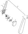
- a ratcheting armrest assembly 10 is illustrated in a disassembled view.
- the ratcheting armrest assembly 10 is configured to be operatively coupled to a seat.
- the ratcheting armrest assembly 10 is coupled to a vehicle seat (not illustrated), but it is to be appreciated that the embodiments disclosed herein may be employed in conjunction with any type of seat.
- the ratcheting armrest assembly 10 includes an articulating frame assembly 12 that is pivotable about an axis A.
- the articulating frame assembly 12 includes a base frame portion 14 and at least one rod 16 extending therefrom.
- the articulating frame assembly 12 provides a structure to which other components are coupled to and substantially corresponds to the overall shape of the ratcheting armrest assembly 10.
- Several ratcheting and anchoring components that will be described in detail below are operatively coupled to the base frame portion 14 of the articulating frame assembly 12.
- the ratcheting and anchoring components are at least partially enclosed between the base frame portion 14 and a mechanism cover 18.
- the mechanism cover 18 is operatively coupled to the base frame portion 14.
- mechanism cover 18 In some embodiments, mechanical fasteners such as bolts, screws, or the like are employed to secure the mechanism cover 18 to the base frame portion 14, however, it is to be understood that any suitable coupling process may be employed.
- the mechanism cover 18, the ratcheting and anchoring components, and the articulating frame assembly 12 are surrounded by an armrest cover 20 that forms an outer surface of the ratcheting armrest assembly 10, which the user directly interacts with.
- the ratcheting armrest assembly 10 includes an anchor assembly 22.
- the anchor assembly 22 is formed of an anchor main plate 24 with an aperture extending therethrough and aligned coaxially with pivot axis A.
- a pivot pin 28 that is coupled to the anchor main plate 24, or integrally formed therewith, extends through the aperture and through an aperture 26 defined by the base frame portion 14 of the articulating frame assembly 12.
- the pivot pin 28 pivotally couples the anchor assembly 22 to the articulating frame assembly 12.
- a ratchet housing 30 is operatively coupled to, or integrally formed with, the anchor main plate 24.
- the ratchet housing 30 includes a first recess 32 and a second recess 34.
- the first recess 32 is sized to receive a first portion 36 of a ratchet 38 and the second recess 34 is sized to receive a second leg 68 of a directional spring 60.
- the ratchet housing 30 includes protrusions that are fittingly received within recesses of the ratchet 38. Irrespective of the precise configuration, the ratchet 38 is fixed to the anchor assembly 22 via the ratchet housing 30.
- the ratchet 38 is part of a locking mechanism assembly 50 that selectively locks the ratcheting armrest assembly with respect to the overall seat to which it is operatively coupled, thereby preventing rotation of the ratcheting armrest assembly 10.
- the locking mechanism assembly 50 is configured such that a vehicle user or occupant can adjust the rotational (i.e., angular) position of the ratcheting armrest assembly relative to the seat to optimize comfort. More specifically, the locking mechanism assembly 50 selectively locks the ratcheting armrest assembly 10 in any one of a plurality of different rotational positions.
- the locking mechanism assembly 50 includes the above-described ratchet 38 and a ratchet anchor 52.
- the ratchet 38 includes an arcuate-shaped surface having a first plurality of teeth 54.
- the ratchet anchor 52 is operatively coupled to the base frame portion 14 of the articulating frame assembly 12 in a fixed manner that allows it to rotate with the articulating frame assembly 12 relative to the anchor assembly 22.
- the ratchet anchor 52 includes an arcuate-shaped surface having a second plurality of teeth 56.
- the ratchet 38 and the ratchet anchor 52 are arranged such that, when the armrest assembly 10, including the ratchet anchor 52, is rotated counterclockwise (e.g., upwardly) in the illustrated embodiment about axis A relative to the anchor assembly 22, the ratchet anchor 52 slides across the ratchet 38, and, more specifically, the second plurality of teeth 56 slides across the first plurality of teeth 54.
- the teeth 54, 56 are not self-locking in the upward direction; that is, the teeth 54, 56 do not prevent rotation of the armrest assembly 10 about axis A in the upward direction.
- the second plurality of teeth 56 force the first plurality of teeth 54 away from the ratchet anchor 52 as each of the teeth 56 traverses over a respective one of the teeth 54 until further rotation causes each of the teeth 56 to rest in respective spaces between the teeth 54.
- the teeth 54, 56 are self-locking in the clockwise (e.g., downward) rotational direction about axis A. That is, a force exerted on the armrest assembly 10 urging the armrest to rotate in the downward direction about axis A will not result in rotation of the armrest assembly 10 because the teeth 54, 56 will be locked and prevent such movement. However, as noted above, when a force is exerted on the armrest assembly 10 urging the armrest to rotate about axis A in an upward rotational direction, teeth 56 will slide across teeth 54, thereby permitting the armrest assembly 10 to rotate.
- the armrest assembly 10 is prevented from rotating downwardly due to the self-locking arrangement of the ratchet 38 and ratchet anchor 52.
- the ratchet 38 is biased into engagement with the ratchet anchor 52 based on a force exerted on the ratchet 38 with a directional spring 60.
- the directional spring 60 includes a curved main portion 62 and first and second legs 64, 68 extending therefrom in a direction substantially parallel to axis A.
- the second leg 68 of the spring 60 is disposed within the second recess 34 of the ratchet housing 30 and the first leg 64 is disposed within a recess 72 of the ratchet 38.
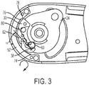
- the spring 60 biases the ratchet 38 toward the ratchet anchor 52, as shown in FIG. 3 .
- the force direction of the spring 60 is dictated by an angle defined by two axes.
- a first axis 80 extends through the respective end locations of the first and second legs 64, 68 of the spring 60.
- the second axis 82 extends through the end location of the first leg 64 and an axis extending centrally through the first portion 40 of the ratchet 38. This defines an angle ⁇ .
- the ratchet 38 engages a cam 78 of the ratchet anchor 52 that manipulates the orientation of the ratchet 38 to cross axis 82 over axis 80, thereby modifying angle ⁇ to an extent necessary to switch the directional force of the spring 60.
- the spring 60 biases the ratchet 38 away from the ratchet anchor 52 to a disengaged condition.
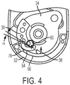
- the teeth 54, 56 are not engaged and clearance is provided therebetween. This condition allows the armrest assembly 10 to be freely rotated downwardly.
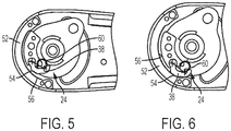
- FIG. 5 shows the armrest assembly 10 in first position as it approaches the first end 74 of the ratchet anchor teeth 56. In this position, the teeth 54, 56 are still disengaged with clearance therebetween.
- FIG. 6 re-engagement is achieved upon contact between the ratchet 38 and a cover plate 90 ( FIG. 1 ). Specifically, the ratchet 38 contacts a cam extending from the cover plate 90. The cam manipulates the ratchet 38 to an orientation that switches the force direction of the spring 60, which has been described in detail above. This forces re-engagement of the teeth 54, 56, allowing a user to leave the armrest assembly 10 in the downward-most position or maneuver it upwardly to a desired angle.
- the cam comprises a bent steel tab.
Landscapes
- Engineering & Computer Science (AREA)
- Aviation & Aerospace Engineering (AREA)
- Transportation (AREA)
- Mechanical Engineering (AREA)
- Seats For Vehicles (AREA)
Description
- The subject matter disclosed herein relates to moveable armrests and, more particularly, to a ratcheting armrest assembly.
- Many vehicles, such as automobiles, include an armrest adjacent an occupant's seat. Armrests are typically cushioned for comfort, may be pivotably adjustable, and may be finished in the same material as the rest of the seat. When travelling in an automobile, a properly adjusted armrest can increase the comfort of a user, thereby improving the user's perception of overall quality of a vehicle. Unfortunately, adjustment of armrests is often cumbersome and potentially discouraging for an occupant to make the proper adjustment. It is for example known from document
JP 3 463767 B2 - The invention is defined by the technical features and method steps set forth in independent product claim 1 and
independent method claim 10, respectively; additional features are disclosed in the dependent claims. - The subject matter, which is regarded as the disclosure, is particularly pointed out and distinctly claimed in the claims at the conclusion of the specification. The foregoing and other features, and advantages of the disclosure are apparent from the following detailed description taken in conjunction with the accompanying drawings in which:
-
FIG. 1 is a disassembled view of a ratcheting armrest assembly; -
FIG. 2 is an enlarged, disassembled view of Section II ofFIG. 1 ; -
FIG. 3 is an elevational view of the ratcheting armrest assembly in an engaged first position, the assembly rotating in a first direction; -
FIG. 4 is an elevational view of the ratcheting armrest assembly in a disengaged second position, the assembly rotating in the first direction; -
FIG. 5 is an elevational view of the ratcheting armrest assembly in a disengaged first position, the assembly rotating in a second direction; and -
FIG. 6 is an elevational view of the ratcheting armrest assembly in an engaged second position, the assembly rotating in the second direction. - The detailed description explains embodiments of the disclosure, together with advantages and features, by way of example with reference to the drawings.
- Referring to
FIG. 1 , a ratchetingarmrest assembly 10 is illustrated in a disassembled view. Theratcheting armrest assembly 10 is configured to be operatively coupled to a seat. In some embodiments, theratcheting armrest assembly 10 is coupled to a vehicle seat (not illustrated), but it is to be appreciated that the embodiments disclosed herein may be employed in conjunction with any type of seat. - The
ratcheting armrest assembly 10 includes an articulatingframe assembly 12 that is pivotable about an axis A. The articulatingframe assembly 12 includes abase frame portion 14 and at least onerod 16 extending therefrom. The articulatingframe assembly 12 provides a structure to which other components are coupled to and substantially corresponds to the overall shape of theratcheting armrest assembly 10. Several ratcheting and anchoring components that will be described in detail below are operatively coupled to thebase frame portion 14 of the articulatingframe assembly 12. The ratcheting and anchoring components are at least partially enclosed between thebase frame portion 14 and a mechanism cover 18. The mechanism cover 18 is operatively coupled to thebase frame portion 14. In some embodiments, mechanical fasteners such as bolts, screws, or the like are employed to secure the mechanism cover 18 to thebase frame portion 14, however, it is to be understood that any suitable coupling process may be employed. The mechanism cover 18, the ratcheting and anchoring components, and the articulatingframe assembly 12 are surrounded by an armrest cover 20 that forms an outer surface of theratcheting armrest assembly 10, which the user directly interacts with. - Referring now to
FIG. 2 and3 , with continued reference toFIG. 1 , theratcheting armrest assembly 10 includes ananchor assembly 22. Theanchor assembly 22 is formed of an anchormain plate 24 with an aperture extending therethrough and aligned coaxially with pivot axis A. Apivot pin 28 that is coupled to the anchormain plate 24, or integrally formed therewith, extends through the aperture and through anaperture 26 defined by thebase frame portion 14 of the articulatingframe assembly 12. Thepivot pin 28 pivotally couples theanchor assembly 22 to the articulatingframe assembly 12. Aratchet housing 30 is operatively coupled to, or integrally formed with, the anchormain plate 24. Theratchet housing 30 includes afirst recess 32 and asecond recess 34. Thefirst recess 32 is sized to receive afirst portion 36 of aratchet 38 and thesecond recess 34 is sized to receive asecond leg 68 of adirectional spring 60. Conversely, it is contemplated that theratchet housing 30 includes protrusions that are fittingly received within recesses of theratchet 38. Irrespective of the precise configuration, theratchet 38 is fixed to theanchor assembly 22 via theratchet housing 30. - The
ratchet 38 is part of alocking mechanism assembly 50 that selectively locks the ratcheting armrest assembly with respect to the overall seat to which it is operatively coupled, thereby preventing rotation of theratcheting armrest assembly 10. Thelocking mechanism assembly 50 is configured such that a vehicle user or occupant can adjust the rotational (i.e., angular) position of the ratcheting armrest assembly relative to the seat to optimize comfort. More specifically, thelocking mechanism assembly 50 selectively locks theratcheting armrest assembly 10 in any one of a plurality of different rotational positions. - The
locking mechanism assembly 50 includes the above-describedratchet 38 and aratchet anchor 52. Theratchet 38 includes an arcuate-shaped surface having a first plurality ofteeth 54. Theratchet anchor 52 is operatively coupled to thebase frame portion 14 of the articulatingframe assembly 12 in a fixed manner that allows it to rotate with the articulatingframe assembly 12 relative to theanchor assembly 22. Theratchet anchor 52 includes an arcuate-shaped surface having a second plurality ofteeth 56. - The
ratchet 38 and theratchet anchor 52 are arranged such that, when thearmrest assembly 10, including theratchet anchor 52, is rotated counterclockwise (e.g., upwardly) in the illustrated embodiment about axis A relative to theanchor assembly 22, theratchet anchor 52 slides across theratchet 38, and, more specifically, the second plurality ofteeth 56 slides across the first plurality ofteeth 54. Theteeth teeth armrest assembly 10 about axis A in the upward direction. As theratchet anchor 52 slides across theratchet 38, the second plurality ofteeth 56 force the first plurality ofteeth 54 away from theratchet anchor 52 as each of theteeth 56 traverses over a respective one of theteeth 54 until further rotation causes each of theteeth 56 to rest in respective spaces between theteeth 54. - The
teeth armrest assembly 10 urging the armrest to rotate in the downward direction about axis A will not result in rotation of thearmrest assembly 10 because theteeth armrest assembly 10 urging the armrest to rotate about axis A in an upward rotational direction,teeth 56 will slide acrossteeth 54, thereby permitting thearmrest assembly 10 to rotate. - As described above, the
armrest assembly 10 is prevented from rotating downwardly due to the self-locking arrangement of theratchet 38 andratchet anchor 52. Theratchet 38 is biased into engagement with theratchet anchor 52 based on a force exerted on theratchet 38 with adirectional spring 60. Thedirectional spring 60 includes a curvedmain portion 62 and first andsecond legs second leg 68 of thespring 60 is disposed within thesecond recess 34 of theratchet housing 30 and thefirst leg 64 is disposed within arecess 72 of theratchet 38. Over the range between afirst end 74 of theratchet anchor teeth 56 and asecond end 76 of theratchet anchor teeth 56, thespring 60 biases theratchet 38 toward theratchet anchor 52, as shown inFIG. 3 . The force direction of thespring 60 is dictated by an angle defined by two axes. Afirst axis 80 extends through the respective end locations of the first andsecond legs spring 60. Thesecond axis 82 extends through the end location of thefirst leg 64 and an axis extending centrally through thefirst portion 40 of theratchet 38. This defines an angle α. - Referring to
FIG. 4 , upon reaching thesecond end 76 of theratchet anchor teeth 56, theratchet 38 engages acam 78 of theratchet anchor 52 that manipulates the orientation of theratchet 38 tocross axis 82 overaxis 80, thereby modifying angle α to an extent necessary to switch the directional force of thespring 60. Upon reaching this critical angle, thespring 60 biases theratchet 38 away from theratchet anchor 52 to a disengaged condition. In the disengaged condition shown inFIG. 4 , theteeth armrest assembly 10 to be freely rotated downwardly. - Referring now to
FIGS. 5 and 6 , re-engagement of theratchet 38 with theratchet anchor 52 is illustrated. In particular,FIG. 5 shows thearmrest assembly 10 in first position as it approaches thefirst end 74 of theratchet anchor teeth 56. In this position, theteeth FIG. 6 , re-engagement is achieved upon contact between theratchet 38 and a cover plate 90 (FIG. 1 ). Specifically, theratchet 38 contacts a cam extending from the cover plate 90. The cam manipulates theratchet 38 to an orientation that switches the force direction of thespring 60, which has been described in detail above. This forces re-engagement of theteeth armrest assembly 10 in the downward-most position or maneuver it upwardly to a desired angle. In some embodiments, the cam comprises a bent steel tab.
Claims (10)
- A ratcheting armrest assembly (10) comprising:an articulating frame assembly (12);a ratchet anchor (52) operatively coupled to the articulating frame assembly (12) for rotation with the articulating frame assembly (12);an anchor assembly (22) operatively coupled to the articulating frame assembly (12);a ratchet (38) operatively coupled to the anchor assembly (22);the ratchet (38) including a first plurality of teeth (54) and the ratchet anchor (52) including a second plurality of teeth (56), wherein the first plurality of teeth (54) and the second plurality of teeth (56) are engageable with each other, the second plurality of teeth (56) free to rotate relative to the first plurality of teeth (54) in a first rotational direction and self-locking with the first plurality of teeth (54) in a second rotational direction; anda directional spring (60) biasing the ratchet (38) in the second direction in a first orientation and in the first direction in a second orientation,wherein the directional spring (60) is operatively coupled to the ratchet (38), the directional spring (60) comprising a curved main portion (62), a first leg (64) and a second leg (68), characterised in that the second leg (68) of the directional spring (60) is disposed along a first portion (70) of the ratchet (38), and in that the second leg (68) is able to be in contact with a surface of the ratchet (38), the first leg (64) being disposed within a recess (72) of the ratchet (38).
- The ratcheting armrest assembly (10) of claim 1, wherein the anchor assembly (22) is operatively coupled to the frame assembly (12) via a pivot pin (28) extending through an aperture (26) of the articulating frame assembly (12) and along an axis (A) of rotation of the articulating frame assembly (12).
- The ratcheting armrest assembly (10) of claim 2, wherein the frame assembly (12) rotates relative to the anchor assembly (22).
- The ratcheting armrest assembly (10) of claim 1, wherein the anchor assembly (22) includes a ratchet housing (30), the ratchet (38) coupled to the ratchet housing (30).
- The ratcheting armrest assembly (10) of claim 4, wherein the ratchet housing (30) includes a first recess (32) retaining a first portion (36) of the ratchet (38) and a second recess (34) retaining a second portion (40) of the ratchet (38).
- The ratcheting armrest assembly (10) of anyone of claims 1-5, wherein a first angle defining axis (80) extends through respective ends of the first leg (64) and the second leg (68), wherein a second angle defining axis (82) extends through the end of the first leg (64) and an axis extending centrally through a first portion (36) of the ratchet (38).
- The ratcheting armrest assembly (10) of claim 6, wherein the first orientation of the directional spring (60) is defined by a positive angle between the first angle defining axis (80) and the second angle defining axis (82), the second orientation of the directional spring (60) defined by a negative angle between the first angle defining axis (80) and the second angle defining axis (82).
- The ratcheting armrest assembly (10) of claim 7, the ratchet anchor (52) including a first cam disposed proximate an end of the second plurality of teeth, wherein contact between the ratchet (38) and the first cam shift the directional spring (60) from the first orientation to the second orientation to provide a clearance between the first plurality of teeth (54) and the second plurality of teeth (56).
- The ratcheting armrest assembly (10) of claim 7, further comprising a cover plate (90) disposed between the ratchet anchor (52) and a mechanism cover (18), the cover plate (90) including a second cam disposed proximate an end of the second plurality of teeth (56), wherein contact between the ratchet (38) and the second cam shift the directional spring from the second orientation to the first orientation to re-engage the first plurality of teeth (54) and the second plurality of teeth (56).
- A method of assembling a ratcheting armrest assembly (10) of any of claims 1-9 for a vehicle comprising:disposing a pivot pin (28) of an anchor assembly (22) through an aperture (26) defined by an articulating frame assembly (12), the pivot pin (28) extending along an axis of rotation of the articulating frame assembly (12);coupling a ratchet (38) to the anchor assembly (22) by inserting a first portion (36) of the ratchet (38) into a first recess (36) of a ratchet housing (30);coupling a ratchet anchor (52) to the articulating frame assembly (12), the ratchet (38) including a first plurality of teeth (54) and the ratchet anchor (52) including a second plurality of teeth (56), wherein the first plurality of teeth (54) and the second plurality of teeth (56) are engageable with each other, the second plurality of teeth (56) free to rotate relative to the first plurality of teeth (54) in a first rotational direction and self-locking with the first plurality of teeth (54) in a second rotational direction; andcoupling a directional spring (60) to the ratchet (38) to bias the ratchet (38) in the second direction in a first orientation and in the first direction in a second orientation.
Applications Claiming Priority (1)
| Application Number | Priority Date | Filing Date | Title |
|---|---|---|---|
| US201562167361P | 2015-05-28 | 2015-05-28 |
Publications (2)
| Publication Number | Publication Date |
|---|---|
| EP3098110A1 EP3098110A1 (en) | 2016-11-30 |
| EP3098110B1 true EP3098110B1 (en) | 2019-11-06 |
Family
ID=56072271
Family Applications (1)
| Application Number | Title | Priority Date | Filing Date |
|---|---|---|---|
| EP16170987.8A Active EP3098110B1 (en) | 2015-05-28 | 2016-05-24 | Ratcheting armrest assembly for a vehicle |
Country Status (4)
| Country | Link |
|---|---|
| US (1) | US9821691B2 (en) |
| EP (1) | EP3098110B1 (en) |
| CN (1) | CN106183918B (en) |
| ES (1) | ES2755507T3 (en) |
Families Citing this family (24)
| Publication number | Priority date | Publication date | Assignee | Title |
|---|---|---|---|---|
| USRE47872E1 (en) | 2011-07-11 | 2020-02-25 | Molon Labe Llc | Slider seat for aircraft |
| US9603456B2 (en) * | 2015-07-06 | 2017-03-28 | Yu-Shan Lai | Rotating device for armrest |
| DE102015014723B4 (en) * | 2015-11-17 | 2025-11-06 | Grammer Aktiengesellschaft | Vehicle equipment and armrest |
| DE102016003992A1 (en) * | 2016-04-07 | 2017-10-12 | Grammer Ag | armrest |
| US10569881B2 (en) | 2016-10-18 | 2020-02-25 | Molon Labe, Llc | Staggered aircraft seat assembly |
| CN107187357B (en) * | 2017-05-31 | 2023-04-18 | 安道拓(重庆)汽车部件有限公司 | Armrest locking mechanism and automobile seat armrest with armrest locking mechanism |
| USD840701S1 (en) * | 2017-10-18 | 2019-02-19 | Molon Labe, Llc | Staggered aircraft seats |
| USD850177S1 (en) | 2017-12-15 | 2019-06-04 | Molon Labe, Llc | Aircraft seat armrests |
| USD867775S1 (en) | 2018-04-03 | 2019-11-26 | Molon Labe, Llc | Set of multilevel aircraft seat armrests |
| CN108725281B (en) * | 2018-07-24 | 2024-04-19 | 江苏忠明祥和精工股份有限公司 | Armrest locking device for automobile seat |
| CN109823245A (en) * | 2018-10-18 | 2019-05-31 | 贵州华阳汽车零部件有限公司 | A kind of automobile seat arm freely adjusting angle |
| CN109774565B (en) * | 2018-12-22 | 2021-04-23 | 南京灵雀智能制造有限公司 | A bus stop fixer |
| KR102031263B1 (en) * | 2019-04-19 | 2019-10-11 | 주식회사 우보테크 | Tilting Device for Armrest |
| KR102218850B1 (en) * | 2019-05-17 | 2021-02-23 | 주식회사다스 | Armrest Angle Adjustment for Automobile Seat |
| KR102273729B1 (en) * | 2019-07-16 | 2021-07-07 | 대원산업 주식회사 | Angle adjustment kit for arm rest |
| USD936383S1 (en) | 2019-08-01 | 2021-11-23 | Molon Labe, Llc | Staggered aircraft seat assembly |
| USD924043S1 (en) | 2019-08-22 | 2021-07-06 | Molon Labe, Llc | Aircraft wheelchair accommodating seat assembly |
| US11478084B2 (en) | 2020-08-03 | 2022-10-25 | Ami Industries, Inc. | Seat assembly and system |
| CN113352972B (en) * | 2021-06-07 | 2022-07-12 | 舒茨曼座椅(宁波)有限公司 | Horizontal stop device of handrail, seat and car |
| EP4223586B1 (en) * | 2022-02-04 | 2025-01-01 | Martur Sünger Ve Koltuk Tesisleri Ticaret Ve Sanayi A.S | Armrest assembly, in particular for vehicle seats |
| US12503236B2 (en) * | 2022-06-10 | 2025-12-23 | Safran Seats Usa Llc | Concentric armrest pivot |
| FR3145319B1 (en) * | 2023-01-30 | 2025-01-10 | Safran Seats | ARMREST WITH ROTATIONAL ADJUSTMENT SYSTEM |
| KR102843116B1 (en) * | 2023-02-15 | 2025-08-07 | 주식회사 우보테크 | Arm rest tilting apparatus |
| CN117141325A (en) * | 2023-10-20 | 2023-12-01 | 嘉兴德鑫电子科技有限公司 | An armrest movement mechanism and automobile |
Family Cites Families (17)
| Publication number | Priority date | Publication date | Assignee | Title |
|---|---|---|---|---|
| GB2023710A (en) * | 1977-10-18 | 1980-01-03 | Uop Inc | Locking seat hinges |
| US4655501A (en) * | 1985-07-25 | 1987-04-07 | Nhk Spring Co., Ltd. | Armrest of a seat |
| US5489143A (en) * | 1993-09-06 | 1996-02-06 | Suncall Corporation | Arm rest device |
| JP3463767B2 (en) | 1994-07-12 | 2003-11-05 | アラコ株式会社 | Armrest support structure |
| US5597209A (en) * | 1995-05-11 | 1997-01-28 | Hoover Universal, Inc. | Adjustable vehicle seat armrest with a ratchet |
| US5702157A (en) * | 1996-08-23 | 1997-12-30 | Tachi-S Engineering, U.S.A., Inc. | Adjustable armrest mechanism |
| US5984416A (en) * | 1998-04-30 | 1999-11-16 | Calvin College | Adjustable armrest |
| DE19840808B4 (en) | 1998-09-07 | 2005-11-10 | Audi Ag | Adjusting mechanism for a pivoting comfort element |
| FR2784426B1 (en) * | 1998-10-13 | 2000-12-15 | Marc Lefevere | STRUCTURE FOR AN AUTOMATIC DEVICE FOR INDEX GUIDANCE OF A MOBILE PART |
| US6467847B2 (en) * | 2001-01-19 | 2002-10-22 | Johnson Controls Technology Company | Comfort armrest with memory |
| KR100554450B1 (en) * | 2003-05-07 | 2006-03-03 | 주식회사 우보테크 | Car Armrests |
| DE102004011385B4 (en) | 2004-03-05 | 2006-05-04 | Johnson Controls Gmbh | Device for angular adjustment of a rotatable about a rotation axis provided component, in particular an armrest in a vehicle |
| US20080030061A1 (en) * | 2006-08-04 | 2008-02-07 | Srinivas Pejathaya | Multi-position adjustment mechanism |
| WO2012073273A1 (en) * | 2010-11-30 | 2012-06-07 | 東海化成工業株式会社 | Armrest device |
| US8702174B2 (en) * | 2011-09-27 | 2014-04-22 | Bae Industries, Inc. | Armrest exhibiting multiple stacked and fixed sectors in alignment with retractable pawls and exhibiting offset engaging teeth for ensuring incremental pivotal adjustability |
| CN202966024U (en) * | 2011-11-07 | 2013-06-05 | 爱信精机株式会社 | Seat adjusting device for vehicles |
| CN203402014U (en) * | 2013-08-07 | 2014-01-22 | 江西江铃李尔内饰系统有限公司 | Combining device for automobile chair armrest |
-
2016
- 2016-05-16 US US15/155,826 patent/US9821691B2/en active Active
- 2016-05-24 EP EP16170987.8A patent/EP3098110B1/en active Active
- 2016-05-24 ES ES16170987T patent/ES2755507T3/en active Active
- 2016-05-27 CN CN201610365845.XA patent/CN106183918B/en not_active Expired - Fee Related
Non-Patent Citations (1)
| Title |
|---|
| None * |
Also Published As
| Publication number | Publication date |
|---|---|
| US9821691B2 (en) | 2017-11-21 |
| EP3098110A1 (en) | 2016-11-30 |
| ES2755507T3 (en) | 2020-04-22 |
| US20160347215A1 (en) | 2016-12-01 |
| CN106183918A (en) | 2016-12-07 |
| CN106183918B (en) | 2018-12-25 |
Similar Documents
| Publication | Publication Date | Title |
|---|---|---|
| US9821691B2 (en) | Ratcheting armrest assembly for a vehicle | |
| CA2832350C (en) | Disc recliner with internal leaf springs | |
| EP2406100B1 (en) | Anti-backdrive for continuous disc recliner | |
| US6983995B1 (en) | Linear adjustable head restraint | |
| US7967385B2 (en) | Hinge mechanism and vehicle seat comprising such a mechanism | |
| US6578921B2 (en) | Seat reclining device | |
| US7364237B2 (en) | Seat assembly including a toothed pawl interengageable with a seatback | |
| US20070241603A1 (en) | Armrest Locking Mechanism | |
| US9409503B2 (en) | Ratcheting vehicle head restraint assembly | |
| US7823978B2 (en) | Reclining device | |
| US20070164593A1 (en) | Articulating headrest assembly | |
| US6364413B1 (en) | Articulation mechanism for a vehicle seat | |
| KR101335751B1 (en) | Step-by-step mechanism, in particular for a seat adjustment | |
| US20200047644A1 (en) | Recliner Mechanism For Seat Assembly And Method Of Manufacturing | |
| EP3176029A1 (en) | Four-way ratcheting vehicle head restraint assembly | |
| US20220258651A1 (en) | Release Mechanism For Seat Recliner Assembly | |
| WO2006020313A3 (en) | Vehicule seat back recliner and assembly | |
| US20080122281A1 (en) | Adjusting Mechanism and Vehicle Seat | |
| JP5749023B2 (en) | Seat assembly with elastic torsion spring element | |
| KR101605102B1 (en) | Fitting for a vehicle seat, and vehicle seat | |
| JP3751003B2 (en) | Connecting fastener for vehicle seat and vehicle seat thereof | |
| US5607032A (en) | Rotatable shaft lock apparatus | |
| US7252338B2 (en) | Seat assembly having an adjustable height and angle armrest | |
| US7770975B2 (en) | Locking device | |
| KR102025620B1 (en) | Stepless Height Controlling Headrest |
Legal Events
| Date | Code | Title | Description |
|---|---|---|---|
| PUAI | Public reference made under article 153(3) epc to a published international application that has entered the european phase |
Free format text: ORIGINAL CODE: 0009012 |
|
| AK | Designated contracting states |
Kind code of ref document: A1 Designated state(s): AL AT BE BG CH CY CZ DE DK EE ES FI FR GB GR HR HU IE IS IT LI LT LU LV MC MK MT NL NO PL PT RO RS SE SI SK SM TR |
|
| AX | Request for extension of the european patent |
Extension state: BA ME |
|
| STAA | Information on the status of an ep patent application or granted ep patent |
Free format text: STATUS: REQUEST FOR EXAMINATION WAS MADE |
|
| 17P | Request for examination filed |
Effective date: 20170529 |
|
| RBV | Designated contracting states (corrected) |
Designated state(s): AL AT BE BG CH CY CZ DE DK EE ES FI FR GB GR HR HU IE IS IT LI LT LU LV MC MK MT NL NO PL PT RO RS SE SI SK SM TR |
|
| REG | Reference to a national code |
Ref country code: DE Ref legal event code: R079 Ref document number: 602016023603 Country of ref document: DE Free format text: PREVIOUS MAIN CLASS: B60N0002460000 Ipc: B60N0002750000 |
|
| RIC1 | Information provided on ipc code assigned before grant |
Ipc: B60N 2/75 20180101AFI20190527BHEP |
|
| GRAP | Despatch of communication of intention to grant a patent |
Free format text: ORIGINAL CODE: EPIDOSNIGR1 |
|
| STAA | Information on the status of an ep patent application or granted ep patent |
Free format text: STATUS: GRANT OF PATENT IS INTENDED |
|
| INTG | Intention to grant announced |
Effective date: 20190708 |
|
| GRAS | Grant fee paid |
Free format text: ORIGINAL CODE: EPIDOSNIGR3 |
|
| GRAA | (expected) grant |
Free format text: ORIGINAL CODE: 0009210 |
|
| STAA | Information on the status of an ep patent application or granted ep patent |
Free format text: STATUS: THE PATENT HAS BEEN GRANTED |
|
| AK | Designated contracting states |
Kind code of ref document: B1 Designated state(s): AL AT BE BG CH CY CZ DE DK EE ES FI FR GB GR HR HU IE IS IT LI LT LU LV MC MK MT NL NO PL PT RO RS SE SI SK SM TR |
|
| REG | Reference to a national code |
Ref country code: GB Ref legal event code: FG4D |
|
| REG | Reference to a national code |
Ref country code: AT Ref legal event code: REF Ref document number: 1198301 Country of ref document: AT Kind code of ref document: T Effective date: 20191115 Ref country code: CH Ref legal event code: EP |
|
| REG | Reference to a national code |
Ref country code: IE Ref legal event code: FG4D |
|
| REG | Reference to a national code |
Ref country code: DE Ref legal event code: R096 Ref document number: 602016023603 Country of ref document: DE |
|
| REG | Reference to a national code |
Ref country code: SE Ref legal event code: TRGR |
|
| REG | Reference to a national code |
Ref country code: NL Ref legal event code: MP Effective date: 20191106 |
|
| REG | Reference to a national code |
Ref country code: LT Ref legal event code: MG4D |
|
| REG | Reference to a national code |
Ref country code: ES Ref legal event code: FG2A Ref document number: 2755507 Country of ref document: ES Kind code of ref document: T3 Effective date: 20200422 |
|
| PG25 | Lapsed in a contracting state [announced via postgrant information from national office to epo] |
Ref country code: GR Free format text: LAPSE BECAUSE OF FAILURE TO SUBMIT A TRANSLATION OF THE DESCRIPTION OR TO PAY THE FEE WITHIN THE PRESCRIBED TIME-LIMIT Effective date: 20200207 Ref country code: PL Free format text: LAPSE BECAUSE OF FAILURE TO SUBMIT A TRANSLATION OF THE DESCRIPTION OR TO PAY THE FEE WITHIN THE PRESCRIBED TIME-LIMIT Effective date: 20191106 Ref country code: PT Free format text: LAPSE BECAUSE OF FAILURE TO SUBMIT A TRANSLATION OF THE DESCRIPTION OR TO PAY THE FEE WITHIN THE PRESCRIBED TIME-LIMIT Effective date: 20200306 Ref country code: NO Free format text: LAPSE BECAUSE OF FAILURE TO SUBMIT A TRANSLATION OF THE DESCRIPTION OR TO PAY THE FEE WITHIN THE PRESCRIBED TIME-LIMIT Effective date: 20200206 Ref country code: FI Free format text: LAPSE BECAUSE OF FAILURE TO SUBMIT A TRANSLATION OF THE DESCRIPTION OR TO PAY THE FEE WITHIN THE PRESCRIBED TIME-LIMIT Effective date: 20191106 Ref country code: BG Free format text: LAPSE BECAUSE OF FAILURE TO SUBMIT A TRANSLATION OF THE DESCRIPTION OR TO PAY THE FEE WITHIN THE PRESCRIBED TIME-LIMIT Effective date: 20200206 Ref country code: LV Free format text: LAPSE BECAUSE OF FAILURE TO SUBMIT A TRANSLATION OF THE DESCRIPTION OR TO PAY THE FEE WITHIN THE PRESCRIBED TIME-LIMIT Effective date: 20191106 Ref country code: LT Free format text: LAPSE BECAUSE OF FAILURE TO SUBMIT A TRANSLATION OF THE DESCRIPTION OR TO PAY THE FEE WITHIN THE PRESCRIBED TIME-LIMIT Effective date: 20191106 Ref country code: NL Free format text: LAPSE BECAUSE OF FAILURE TO SUBMIT A TRANSLATION OF THE DESCRIPTION OR TO PAY THE FEE WITHIN THE PRESCRIBED TIME-LIMIT Effective date: 20191106 |
|
| PG25 | Lapsed in a contracting state [announced via postgrant information from national office to epo] |
Ref country code: IS Free format text: LAPSE BECAUSE OF FAILURE TO SUBMIT A TRANSLATION OF THE DESCRIPTION OR TO PAY THE FEE WITHIN THE PRESCRIBED TIME-LIMIT Effective date: 20200306 Ref country code: HR Free format text: LAPSE BECAUSE OF FAILURE TO SUBMIT A TRANSLATION OF THE DESCRIPTION OR TO PAY THE FEE WITHIN THE PRESCRIBED TIME-LIMIT Effective date: 20191106 Ref country code: RS Free format text: LAPSE BECAUSE OF FAILURE TO SUBMIT A TRANSLATION OF THE DESCRIPTION OR TO PAY THE FEE WITHIN THE PRESCRIBED TIME-LIMIT Effective date: 20191106 |
|
| PG25 | Lapsed in a contracting state [announced via postgrant information from national office to epo] |
Ref country code: AL Free format text: LAPSE BECAUSE OF FAILURE TO SUBMIT A TRANSLATION OF THE DESCRIPTION OR TO PAY THE FEE WITHIN THE PRESCRIBED TIME-LIMIT Effective date: 20191106 |
|
| PG25 | Lapsed in a contracting state [announced via postgrant information from national office to epo] |
Ref country code: EE Free format text: LAPSE BECAUSE OF FAILURE TO SUBMIT A TRANSLATION OF THE DESCRIPTION OR TO PAY THE FEE WITHIN THE PRESCRIBED TIME-LIMIT Effective date: 20191106 Ref country code: DK Free format text: LAPSE BECAUSE OF FAILURE TO SUBMIT A TRANSLATION OF THE DESCRIPTION OR TO PAY THE FEE WITHIN THE PRESCRIBED TIME-LIMIT Effective date: 20191106 Ref country code: RO Free format text: LAPSE BECAUSE OF FAILURE TO SUBMIT A TRANSLATION OF THE DESCRIPTION OR TO PAY THE FEE WITHIN THE PRESCRIBED TIME-LIMIT Effective date: 20191106 Ref country code: CZ Free format text: LAPSE BECAUSE OF FAILURE TO SUBMIT A TRANSLATION OF THE DESCRIPTION OR TO PAY THE FEE WITHIN THE PRESCRIBED TIME-LIMIT Effective date: 20191106 |
|
| REG | Reference to a national code |
Ref country code: DE Ref legal event code: R097 Ref document number: 602016023603 Country of ref document: DE |
|
| REG | Reference to a national code |
Ref country code: AT Ref legal event code: MK05 Ref document number: 1198301 Country of ref document: AT Kind code of ref document: T Effective date: 20191106 |
|
| PG25 | Lapsed in a contracting state [announced via postgrant information from national office to epo] |
Ref country code: SM Free format text: LAPSE BECAUSE OF FAILURE TO SUBMIT A TRANSLATION OF THE DESCRIPTION OR TO PAY THE FEE WITHIN THE PRESCRIBED TIME-LIMIT Effective date: 20191106 Ref country code: SK Free format text: LAPSE BECAUSE OF FAILURE TO SUBMIT A TRANSLATION OF THE DESCRIPTION OR TO PAY THE FEE WITHIN THE PRESCRIBED TIME-LIMIT Effective date: 20191106 |
|
| PLBE | No opposition filed within time limit |
Free format text: ORIGINAL CODE: 0009261 |
|
| STAA | Information on the status of an ep patent application or granted ep patent |
Free format text: STATUS: NO OPPOSITION FILED WITHIN TIME LIMIT |
|
| 26N | No opposition filed |
Effective date: 20200807 |
|
| PG25 | Lapsed in a contracting state [announced via postgrant information from national office to epo] |
Ref country code: AT Free format text: LAPSE BECAUSE OF FAILURE TO SUBMIT A TRANSLATION OF THE DESCRIPTION OR TO PAY THE FEE WITHIN THE PRESCRIBED TIME-LIMIT Effective date: 20191106 Ref country code: SI Free format text: LAPSE BECAUSE OF FAILURE TO SUBMIT A TRANSLATION OF THE DESCRIPTION OR TO PAY THE FEE WITHIN THE PRESCRIBED TIME-LIMIT Effective date: 20191106 |
|
| PG25 | Lapsed in a contracting state [announced via postgrant information from national office to epo] |
Ref country code: MC Free format text: LAPSE BECAUSE OF FAILURE TO SUBMIT A TRANSLATION OF THE DESCRIPTION OR TO PAY THE FEE WITHIN THE PRESCRIBED TIME-LIMIT Effective date: 20191106 Ref country code: CH Free format text: LAPSE BECAUSE OF NON-PAYMENT OF DUE FEES Effective date: 20200531 Ref country code: LI Free format text: LAPSE BECAUSE OF NON-PAYMENT OF DUE FEES Effective date: 20200531 |
|
| REG | Reference to a national code |
Ref country code: BE Ref legal event code: MM Effective date: 20200531 |
|
| PG25 | Lapsed in a contracting state [announced via postgrant information from national office to epo] |
Ref country code: LU Free format text: LAPSE BECAUSE OF NON-PAYMENT OF DUE FEES Effective date: 20200524 |
|
| PG25 | Lapsed in a contracting state [announced via postgrant information from national office to epo] |
Ref country code: IE Free format text: LAPSE BECAUSE OF NON-PAYMENT OF DUE FEES Effective date: 20200524 |
|
| PG25 | Lapsed in a contracting state [announced via postgrant information from national office to epo] |
Ref country code: BE Free format text: LAPSE BECAUSE OF NON-PAYMENT OF DUE FEES Effective date: 20200531 |
|
| REG | Reference to a national code |
Ref country code: ES Ref legal event code: FD2A Effective date: 20210928 |
|
| PG25 | Lapsed in a contracting state [announced via postgrant information from national office to epo] |
Ref country code: ES Free format text: LAPSE BECAUSE OF NON-PAYMENT OF DUE FEES Effective date: 20200525 |
|
| PG25 | Lapsed in a contracting state [announced via postgrant information from national office to epo] |
Ref country code: TR Free format text: LAPSE BECAUSE OF FAILURE TO SUBMIT A TRANSLATION OF THE DESCRIPTION OR TO PAY THE FEE WITHIN THE PRESCRIBED TIME-LIMIT Effective date: 20191106 Ref country code: MT Free format text: LAPSE BECAUSE OF FAILURE TO SUBMIT A TRANSLATION OF THE DESCRIPTION OR TO PAY THE FEE WITHIN THE PRESCRIBED TIME-LIMIT Effective date: 20191106 Ref country code: CY Free format text: LAPSE BECAUSE OF FAILURE TO SUBMIT A TRANSLATION OF THE DESCRIPTION OR TO PAY THE FEE WITHIN THE PRESCRIBED TIME-LIMIT Effective date: 20191106 |
|
| PGFP | Annual fee paid to national office [announced via postgrant information from national office to epo] |
Ref country code: SE Payment date: 20220310 Year of fee payment: 7 |
|
| PG25 | Lapsed in a contracting state [announced via postgrant information from national office to epo] |
Ref country code: MK Free format text: LAPSE BECAUSE OF FAILURE TO SUBMIT A TRANSLATION OF THE DESCRIPTION OR TO PAY THE FEE WITHIN THE PRESCRIBED TIME-LIMIT Effective date: 20191106 |
|
| PGFP | Annual fee paid to national office [announced via postgrant information from national office to epo] |
Ref country code: IT Payment date: 20220412 Year of fee payment: 7 Ref country code: GB Payment date: 20220401 Year of fee payment: 7 Ref country code: FR Payment date: 20220408 Year of fee payment: 7 Ref country code: DE Payment date: 20220329 Year of fee payment: 7 |
|
| REG | Reference to a national code |
Ref country code: DE Ref legal event code: R119 Ref document number: 602016023603 Country of ref document: DE |
|
| REG | Reference to a national code |
Ref country code: SE Ref legal event code: EUG |
|
| GBPC | Gb: european patent ceased through non-payment of renewal fee |
Effective date: 20230524 |
|
| PG25 | Lapsed in a contracting state [announced via postgrant information from national office to epo] |
Ref country code: SE Free format text: LAPSE BECAUSE OF NON-PAYMENT OF DUE FEES Effective date: 20230525 |
|
| PG25 | Lapsed in a contracting state [announced via postgrant information from national office to epo] |
Ref country code: IT Free format text: LAPSE BECAUSE OF NON-PAYMENT OF DUE FEES Effective date: 20230524 Ref country code: DE Free format text: LAPSE BECAUSE OF NON-PAYMENT OF DUE FEES Effective date: 20231201 Ref country code: GB Free format text: LAPSE BECAUSE OF NON-PAYMENT OF DUE FEES Effective date: 20230524 |
|
| PG25 | Lapsed in a contracting state [announced via postgrant information from national office to epo] |
Ref country code: FR Free format text: LAPSE BECAUSE OF NON-PAYMENT OF DUE FEES Effective date: 20230531 |
|
| PG25 | Lapsed in a contracting state [announced via postgrant information from national office to epo] |
Ref country code: IS Free format text: LAPSE BECAUSE OF NON-PAYMENT OF DUE FEES Effective date: 20200306 |