EP3098046A1 - Trim parts forming method and tools - Google Patents
Trim parts forming method and tools Download PDFInfo
- Publication number
- EP3098046A1 EP3098046A1 EP15305813.6A EP15305813A EP3098046A1 EP 3098046 A1 EP3098046 A1 EP 3098046A1 EP 15305813 A EP15305813 A EP 15305813A EP 3098046 A1 EP3098046 A1 EP 3098046A1
- Authority
- EP
- European Patent Office
- Prior art keywords
- insert
- fixed part
- trim
- respect
- main direction
- Prior art date
- Legal status (The legal status is an assumption and is not a legal conclusion. Google has not performed a legal analysis and makes no representation as to the accuracy of the status listed.)
- Granted
Links
Images



Classifications
-
- B—PERFORMING OPERATIONS; TRANSPORTING
- B29—WORKING OF PLASTICS; WORKING OF SUBSTANCES IN A PLASTIC STATE IN GENERAL
- B29C—SHAPING OR JOINING OF PLASTICS; SHAPING OF MATERIAL IN A PLASTIC STATE, NOT OTHERWISE PROVIDED FOR; AFTER-TREATMENT OF THE SHAPED PRODUCTS, e.g. REPAIRING
- B29C51/00—Shaping by thermoforming, i.e. shaping sheets or sheet like preforms after heating, e.g. shaping sheets in matched moulds or by deep-drawing; Apparatus therefor
- B29C51/08—Deep drawing or matched-mould forming, i.e. using mechanical means only
- B29C51/082—Deep drawing or matched-mould forming, i.e. using mechanical means only by shaping between complementary mould parts
- B29C51/087—Deep drawing or matched-mould forming, i.e. using mechanical means only by shaping between complementary mould parts with at least one of the mould parts comprising independently movable sections
-
- B—PERFORMING OPERATIONS; TRANSPORTING
- B29—WORKING OF PLASTICS; WORKING OF SUBSTANCES IN A PLASTIC STATE IN GENERAL
- B29C—SHAPING OR JOINING OF PLASTICS; SHAPING OF MATERIAL IN A PLASTIC STATE, NOT OTHERWISE PROVIDED FOR; AFTER-TREATMENT OF THE SHAPED PRODUCTS, e.g. REPAIRING
- B29C33/00—Moulds or cores; Details thereof or accessories therefor
- B29C33/30—Mounting, exchanging or centering
- B29C33/308—Adjustable moulds
-
- B—PERFORMING OPERATIONS; TRANSPORTING
- B29—WORKING OF PLASTICS; WORKING OF SUBSTANCES IN A PLASTIC STATE IN GENERAL
- B29K—INDEXING SCHEME ASSOCIATED WITH SUBCLASSES B29B, B29C OR B29D, RELATING TO MOULDING MATERIALS OR TO MATERIALS FOR MOULDS, REINFORCEMENTS, FILLERS OR PREFORMED PARTS, e.g. INSERTS
- B29K2023/00—Use of polyalkenes or derivatives thereof as moulding material
- B29K2023/10—Polymers of propylene
- B29K2023/12—PP, i.e. polypropylene
-
- B—PERFORMING OPERATIONS; TRANSPORTING
- B29—WORKING OF PLASTICS; WORKING OF SUBSTANCES IN A PLASTIC STATE IN GENERAL
- B29K—INDEXING SCHEME ASSOCIATED WITH SUBCLASSES B29B, B29C OR B29D, RELATING TO MOULDING MATERIALS OR TO MATERIALS FOR MOULDS, REINFORCEMENTS, FILLERS OR PREFORMED PARTS, e.g. INSERTS
- B29K2105/00—Condition, form or state of moulded material or of the material to be shaped
- B29K2105/04—Condition, form or state of moulded material or of the material to be shaped cellular or porous
-
- B—PERFORMING OPERATIONS; TRANSPORTING
- B29—WORKING OF PLASTICS; WORKING OF SUBSTANCES IN A PLASTIC STATE IN GENERAL
- B29K—INDEXING SCHEME ASSOCIATED WITH SUBCLASSES B29B, B29C OR B29D, RELATING TO MOULDING MATERIALS OR TO MATERIALS FOR MOULDS, REINFORCEMENTS, FILLERS OR PREFORMED PARTS, e.g. INSERTS
- B29K2105/00—Condition, form or state of moulded material or of the material to be shaped
- B29K2105/06—Condition, form or state of moulded material or of the material to be shaped containing reinforcements, fillers or inserts
- B29K2105/12—Condition, form or state of moulded material or of the material to be shaped containing reinforcements, fillers or inserts of short lengths, e.g. chopped filaments, staple fibres or bristles
-
- B—PERFORMING OPERATIONS; TRANSPORTING
- B29—WORKING OF PLASTICS; WORKING OF SUBSTANCES IN A PLASTIC STATE IN GENERAL
- B29K—INDEXING SCHEME ASSOCIATED WITH SUBCLASSES B29B, B29C OR B29D, RELATING TO MOULDING MATERIALS OR TO MATERIALS FOR MOULDS, REINFORCEMENTS, FILLERS OR PREFORMED PARTS, e.g. INSERTS
- B29K2105/00—Condition, form or state of moulded material or of the material to be shaped
- B29K2105/25—Solid
- B29K2105/253—Preform
- B29K2105/256—Sheets, plates, blanks or films
-
- B—PERFORMING OPERATIONS; TRANSPORTING
- B29—WORKING OF PLASTICS; WORKING OF SUBSTANCES IN A PLASTIC STATE IN GENERAL
- B29K—INDEXING SCHEME ASSOCIATED WITH SUBCLASSES B29B, B29C OR B29D, RELATING TO MOULDING MATERIALS OR TO MATERIALS FOR MOULDS, REINFORCEMENTS, FILLERS OR PREFORMED PARTS, e.g. INSERTS
- B29K2311/00—Use of natural products or their composites, not provided for in groups B29K2201/00 - B29K2309/00, as reinforcement
- B29K2311/10—Natural fibres, e.g. wool or cotton
-
- B—PERFORMING OPERATIONS; TRANSPORTING
- B29—WORKING OF PLASTICS; WORKING OF SUBSTANCES IN A PLASTIC STATE IN GENERAL
- B29L—INDEXING SCHEME ASSOCIATED WITH SUBCLASS B29C, RELATING TO PARTICULAR ARTICLES
- B29L2031/00—Other particular articles
- B29L2031/30—Vehicles, e.g. ships or aircraft, or body parts thereof
- B29L2031/3005—Body finishings
- B29L2031/3041—Trim panels
Definitions
- the invention is about forming methods and tools for trim parts of vehicles.
- the invention according to a first aspect concerns a method for manufacturing first and second trim parts of vehicles, the first trim part having a first thickness and the second trim part having a second thickness different from the first thickness.
- the regular trim part for example comprises a NFPP layer (Natural Fiber Poly Propylene), covered by a thin decorated layer.
- the premium trim part comprises a foam layer between the decoration layer and the NFPP layer.
- the decoration layer defines the visible surface, or A-surface, while the NFPP layer defines the non-visible surface, or B-surface.
- the regular and premium trim parts must be integrated in the same interior equipment. They must fit in the interior equipment, with no visible gap between the trim part and the surrounding parts.
- the aim of the invention is thus proposing a method according to which the same mould can be used for manufacturing different trim parts having different thicknesses, and especially used for manufacturing a first trim part that has a compressible layer such as a foam layer, and a second trim part that does not have the compressible layer.
- the method comprises the following steps:
- trim parts having different thicknesses can be formed in the same mould.
- the method allows producing in the same mould a first trim part with a foam layer and a second trim part without a foam layer.
- the front insert final position is adjusted taking into account the final expansion of the compressible layer, for the first trim part with a compressible layer.
- the back insert final position is adjusted as a function of the thickness of the trim part.
- the method of the invention may include as well the following features, considered alone or according to any technically feasible combination:
- the invention is directed to an assembly for manufacturing first and second trim parts of vehicles, the first trim part having a first thickness and the second trim part having a second thickness different from the first thickness, the assembly comprising:
- the assembly of the invention may include as well the following features, considered alone or according to any technically feasible combination:
- Figure 1 shows a cross section of an interior equipment 1 of a vehicle.
- the interior equipment is for example a door panel, a dashboard or any other equipment.
- the vehicle is typically an automobile or a truck.
- the interior equipment shown on the left side of figure 1 comprises a first trim part 3, and another part 5 to which the first trim part 3 is secured, for example by mean of one or several clips 7, welding points or any suitable fixing means.
- the first trim part 3 comprises a non-compressible layer 9, and a compressible layer 11.
- the compressible layer 11 is typically covered by a decorative layer 13.
- the first trim part may also include one or several other layers.
- the first trim part has a first thickness.
- the non-compressible layer 9 is for example a NFPP layer (Natural Fiber Poly Propylene).
- the non-compressible layer is in a plastic material, or in any other material.
- Non compressible layer is understood here as meaning rigid or semi-rigid material which may be formed, with in some case a slight thickness reduction, during a forming operation but which do not expand after the forming operation.
- the compressible layer 11 is typically a foam layer or a 3D textile layer.
- the first trim part 3 comprises a central area 15, where the non-compressible layer 9 is covered by the compressible layer 11, and a surrounding area 17 , where the non-compressible layer 9 is not covered by the compressible layer 11.
- the other part 5 is fixed directly to the surrounding area 17. As shown on the figure 1 , the surrounding area 17 is hidden behind the other part 5. Most of the central area 15 is not located behind the other part 5 and is visible.
- the clips 7 are directly connected to the surrounding area 17.
- the other part 5 has an edge 19, which bears against the decorative layer 13. There is no gap between the decorative layer 13 and the edge 19.
- the decorative layer 13 defines the visible side of the trim part (A-surface) and the non-compressible layer 9 defines the non-visible side of the trim part (B-surface).
- the figure 1 shows on the right side the same interior equipment 1, equipped with a second trim part 21.
- the second trim part 21 does not comprise a compressible layer. It has a second thickness, which is lower than the first thickness.
- the second trim part comprises a non-compressible layer 23. Typically, it comprises a decorative layer 25, covering the non-compressible layer 23.
- the non-compressible layer 23 is a NFPP layer, or a plastic layer, or is in any other adapted material.
- the decorative layer 23 does not cover the non-compressible layer 23.
- the other part 5 is fixed directly to the surrounding area 17.
- the surrounding area 17 is hidden behind the other part 5, whereas the greatest part of the central area 15 is not located behind the other part 5.
- the clips 7 are connected to the surrounding area 17.
- the edge 19 bears against the decorative layer 23, with no gap between the decorative layer 23 and the edge 19.
- the A-surfaces of the first and second trim parts 3, 21 are exactly at the same position, such that there is no gap, even though the first and second trim parts 3, 21 do not have the same thickness.
- the surrounding areas 17 of the first and second trim parts, or at least the zones of the surrounding areas to which the other part 5 is fixed, are at the same positions. In other words, in the first and in the second trim parts 3, 21, the A-surfaces have exactly the same position with respect to the zones of the non-compressible layer 9, 21 to which the other part 5 is fixed.
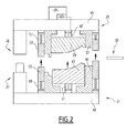
- the first and second trim parts 3, 21 are manufactured using the assembly 26 depicted on the figure 2 .
- the assembly 26 comprises:
- the front tool 29 has a front fixed part 37 and a front movable insert 39 movable with respect to the front fixed part 37 along a main direction.
- the back tool 31 has a back fixed part 41 and a back movable insert 43 movable with respect to the back fixed part 41 along the main direction.
- the front fixed part 37 and the front insert 39 are mounted to a front frame 45.
- the front fixed part 37 is rigidly secured to the front frame 45.
- the front tool 29 includes an actuator 47, for example a cylinder, connecting the front insert 39 to the front frame 45.
- the back fixed part 41 and the back insert 43 are mounted as well to a back frame 49.
- the back fixed part 41 is rigidly secured to the back frame 49.
- the back tool 31 includes an actuator 51, for example a cylinder, or a spring, connecting the back insert 43 to the back frame 49.
- the front and back tools 29, 31 are typically moved with respect to one another along the main direction to open or close the mould 27.
- the front and back fixed parts 37, 41 form between them the surrounding area 17 of the first and second trim parts 3, 21.
- the front and back inserts 39, 43 form between them the central area 15 of the first and second trim parts 3, 21.
- the device 33 for introducing the first or second trim parts 3, 21 in the forming mould 27 is typically a movable frame, equipped with means for clamping the first or second trim parts 3, 21.
- the assembly 26 further includes front and back clamps 53, 55 for clamping the first or second trim parts 3, 21 after it is introduced into the mould 27.
- the front clamp 53 is mounted on the front tool 29 and is moved with the front tool. It is for example connected to the front frame by an actuator 57, for example a cylinder, so that its position along the main direction with respect to the front frame is adjustable selectively.
- the back clamp 55 is mounted on the back tool 31. It is for example connected to the back frame 49 by an actuator 59, for example a cylinder, so that its position along the main direction with respect to the back frame is adjustable.
- the front insert 39 occupies a final front position
- the back insert 43 occupies a final back position
- the front and back inserts 39, 43 defining a gap 61 between them ( figure 3 ).
- the device 35 allows adjusting the followings settings of the mould 27: the final front position of the front insert 39 with respect to the front fixed part 37, and the gap 61 between the front and back insert 39, 43. More precisely, the device 35 allows adjusting the height of the gap 61, taken along the main direction.
- the device 35 in this case comprises a control device 63, controlling the actuator 47 in order to position the front insert 39 at a selected position with respect to the front fixed part 37.
- the mould 27 is arranged such that, when the mould closes by moving the front and back tools 29, 31 toward one another, the central area 15 of the first or second trim part 3, 21 is first pressed by the front insert 39 against the back insert 43, the peripheral area of the first or second trim part 3, 21 being not pressed by the front fixed part 37 against the back fixed part 41 at this stage.
- the back insert 43 is moved with the front insert 39 with respect to the back fixed part 41 along the main direction, until the peripheral area of the first or second trim part 3, 21 is pressed by the front fixed part 37 against the back fixed part 41.
- the gap 61 is controlled for example by adjusting the height of a spacer 63, attached to the front or to the back insert 39, 43, and extending between the front and back insert 39, 43 ( figure 3 ).
- the height of the spacer 63 is controlled by the device 35.
- the first values of the settings are chosen such that, when the first trim part 3 is inside the mould and when the mould 27 is closed (situation of the figure 3 , left side), the front insert 39 has a first front final position along the main direction with respect to the front fixed part 37 and the back insert 43 has a first back final position along the main direction with respect to the back fixed part 41.
- the second values of the settings are chosen such that, when the second trim part 21 is inside the mould 27 and when the mould 27 is closed, the front insert 39 has a second front final position along the main direction with respect to the front fixed part 37 different from the first front final position, and the back insert 43 has a second back final position along the main direction with respect to the back fixed part 41, different from the first back final position.
- the second front final position is shifted away from the back tool 31 along the main direction with respect to the first front final position by a quantity ⁇ A ( figure 3 ), chosen as indicated below.
- the compressible layer 11 is compressed when the mould 27 is in its closed position.
- the compressible layer 11 expands, toward the A-surface.
- the thickness of the compressible layer 11, and of the central part 15 of the first trim part 3, increases by a quantity ⁇ th.
- the order of magnitude of ⁇ th is frequently 1 mm.
- ⁇ A is chosen substantially equal to ⁇ th.
- the surrounding areas 17 of the first and second trim parts 3 and 21 are at the same final position when the mould 27 is closed.
- the A-surface of the second trim part 21 is at the same position with respect to the surrounding area 17 as the A-surface of the first trim part 3, after the expansion ( figure 4 ).
- the second back final position is shifted toward the front tool along the main direction with respect to the first back final position, by a quantity ⁇ B.
- the quantity ⁇ B is chosen according to the following equation:
- the non-compressible layers 9, 23 of the first and second inserts 3, 21, as a consequence, have the same physical properties: density, weight per area.... This point is especially important when the non-compressible layers 9, 23 are made of NFPP or other similar materials.
- the forming mould 27 is in its open position, as shown on figure 2 .
- the manufacturing method comprises the following steps:
- the first trim part 3 is laid down on the back clamping frame 55 by the device 33.
- the first trim part 3 is initially flat, as shown on the figure 5 .
- the first trim part is oriented such that the compressible layer 11 faces the front tool 29, and the non-compressible layer 9 faces the back tool 31.
- the front and back tools 29, 31 are moved toward one another, for closing the mould.
- the front tool 29 is moved along the main direction toward the back tool 31, the back tool being fixed.
- the front tool is fixed and the back tool moves along the main direction, or both the front and back tools move along the main direction.
- the front insert 39 remains at the same position with regard to the front fixed part 37.
- the front insert 39 and the front fixed part 37 are moved as one piece.
- the front clamping frame 53 remains at the same position with regard to the front fixed part 37 as well. It is moved as one piece with the front insert 39 and the front fixed part 37.
- the first part of the travel ends when the first trim part 3 is clamped between the front and back clamping frame 53, 55.
- the back insert 43 remain at the same position with respect to the back fixed part 41.
- the back clamping frame 55 moves with the front clamping frame 53 along the main direction, toward the back tool 31.
- the actuator 59 is passive during the second part of the travel. It is driven by the pressure exerted by the front clamping frame 53 on the back clamping frame 55.
- the second part of the travel ends when the central area 15 of the first trim part 3 is pressed between the front and back inserts 39, 43.
- the back insert 43 moves with the front insert 39 with respect to the back fixed part 41 along the main direction toward the back tool 31.
- the actuator 51 is passive during the third part of the travel. It is driven by the pressure exerted by the front insert 39 on the back insert 43.
- the back clamping frame 55 moves along with the front clamping frame 53 along the main direction, toward the back tool 31.
- the actuator 59 is passive during the third part of the travel. It is driven by the pressure exerted by the front clamping frame 53 on the back clamping frame 55.
- the third part of the travel ends when the surrounding area 17 of the first trim part 3 is pressed between the front and back fixed parts 37, 41.
- the mould 27 is then opened, and the formed first trim part 3 is removed from the mould, typically using the device 33.
- the back clamp 55 and the back insert 43 are brought back to their initial position by the actuators 59 and 51, respectively.
- the front clamping frame 53 is brought back to its initial position by the actuators 57.
- trim parts similar to the first trim part 3, are manufactured as described above, before the settings of the mould are changed.
- the settings of the forming mould 27 are then adjusted to the second values.
- the front insert 39 is moved by mean of the actuator 47 with respect to the front fixed part 37. If necessary, the position of the front clamping frame 53 is adjusted with respect to the front fixed part 37, by mean of the actuator 57.
- the height of the spacer 63 is modified.
- the second trim part 21 is introduced in the forming mould 27, and laid down on the back clamping frame 55 by the device 33.
- the second trim part 21 is initially flat.
- the second trim part 21 is oriented such that the decorative layer 25 faces the front tool 29, and the non-compressible layer 23 faces the back tool 31.
- the mould is then closed.
- the travel of the front and back tools 29, 31 toward one another comprises the same first, second and third parts as described above for the first trim part 3.
- the invention has been described for an example in which two trim parts, with different thicknesses, are manufactured. However, the invention encompasses cases where three trim parts, having thicknesses different from one to another, are manufactured, or more than three trim parts. For instance the third trim part do not have a decorative layer.
- the settings of the mould typically are adjustable such that the front and back final positions are freely selected each in a continuous range.
- front and back tools are not used in a limitative way.
- the two halves of a mold are placed above one another and are moved vertically, as shown on the figures.
- the invention could be implemented with the front and back tool moving along a horizontal direction with respect to one another.
- the main direction, along which the front and back inserts move with respect to the front and back fixed parts, is horizontal.
- the front tool is above the back tool in the example depicted on the figures. In another example, the back tool is above the front tool.
- the first and second trim parts in the example described above, respectively have a compressible layer, and do not have a compressible layer. According to another example, the first and second trim parts both have a compressible layer.
- the first and second front final positions are then chosen taking into account the expansion of the compressible layer of the two trim parts, such that the A-surface of the first and second trim parts are at the same position with respect to the respective surrounding areas of the first and second trim parts.
- the first and second trim parts both do not have a compressible layer.
- the settings adjustment device could adjust the followings settings of the mould: the final front position of the front insert with respect to the front fixed part, and the final back position of the back insert with respect to the back fixed part.
- the back insert remain fixed with respect of the back fixed part during all the travel of the front and back tools toward one another.
- the non-compressible layer is turned toward the back tool, and the back tool has a back insert which is pushed back by the front insert during the third part of the travel of the front and back tools toward one another.
- the compressible layer faces the front tool.
- the non-compressible layer faces the front tool, and the compressible layer faces the back tool.
Landscapes
- Engineering & Computer Science (AREA)
- Mechanical Engineering (AREA)
- Moulds For Moulding Plastics Or The Like (AREA)
- Vehicle Interior And Exterior Ornaments, Soundproofing, And Insulation (AREA)
- Injection Moulding Of Plastics Or The Like (AREA)
Abstract
- introducing the first trim part (3) and the second trim part (21) between a front and a back tool (29, 31) of the forming mould (27), the front tool (29) having a front fixed part (37) and a front movable insert (39) movable with respect to the front fixed part (37) along a main direction, the back tool (31) having a back fixed part (41) and a back movable insert (43) movable with respect to the back fixed part along the main direction;
- adjusting settings of the forming mould (27) to different values for the first and second trim parts;
- when the forming mould (27) is closed, the front insert (39) has a front final position along the main direction with respect to the front fixed part (37) function of the settings, and the back insert (43) has a back final position along the main direction with respect to the back fixed part (41) function of the settings.
Description
- The invention is about forming methods and tools for trim parts of vehicles.
- More specifically, the invention according to a first aspect concerns a method for manufacturing first and second trim parts of vehicles, the first trim part having a first thickness and the second trim part having a second thickness different from the first thickness.
- Indeed, car manufacturers usually propose, for the same type of car, regular trim parts and premium trim parts, with different coverings or finishes. The regular trim part for example comprises a NFPP layer (Natural Fiber Poly Propylene), covered by a thin decorated layer. The premium trim part comprises a foam layer between the decoration layer and the NFPP layer.
- The decoration layer defines the visible surface, or A-surface, while the NFPP layer defines the non-visible surface, or B-surface. The regular and premium trim parts must be integrated in the same interior equipment. They must fit in the interior equipment, with no visible gap between the trim part and the surrounding parts.
- It is possible to produce the first and second trim parts in different forming moulds. However, it is necessary in this case to buy two differents moulds, and the investment cost as a consequence is high.
- The aim of the invention is thus proposing a method according to which the same mould can be used for manufacturing different trim parts having different thicknesses, and especially used for manufacturing a first trim part that has a compressible layer such as a foam layer, and a second trim part that does not have the compressible layer.
- According to the invention, the method comprises the following steps:
- adjusting settings of a forming mould to first values;
- introducing the first trim part between a front and a back tool of the forming mould, the front tool having a front fixed part and a front movable insert movable with respect to the front fixed part along a main direction, the back tool having a back fixed part and a back movable insert movable with respect to the back fixed part along the main direction;
- closing the forming mould, the first values of the settings being chosen such that, when the forming mould is closed, the front insert has a first front final position along the main direction with respect to the front fixed part and the back insert has a first back final position along the main direction with respect to the back fixed part;
- adjusting settings of the forming mould to second values different from the first values;
- introducing the second trim part between front and back tools of the forming mould;
- closing the forming mould, the second values of the settings being chosen such that, when the forming mould is closed, the front insert has a second front final position along the main direction with respect to the front fixed part different from the first front final position, and the back insert has a second back final position along the main direction with respect to the back fixed part, different from the first back final position.
- Since the front and back inserts final positions can be adjusted by changing the settings of the mould, trim parts having different thicknesses can be formed in the same mould.
- Moreover, and as explained in a more detailed manner below, the method allows producing in the same mould a first trim part with a foam layer and a second trim part without a foam layer. The front insert final position is adjusted taking into account the final expansion of the compressible layer, for the first trim part with a compressible layer. The back insert final position is adjusted as a function of the thickness of the trim part.
- The method of the invention may include as well the following features, considered alone or according to any technically feasible combination:
- the settings comprise the front final position of the front insert along the main direction with respect to the front fixed part and the gap between the front insert and the back insert when the forming mould is closed;
- the front and back tools are moved one toward the other when the forming mould closes, the first trim part having a non-compressible layer toward the back tool and a compressible layer toward the front tool, the second trim part having no compressible layer and the second thickness being lower than the first thickness, the second front final position being shifted away from the back tool along the main direction with respect to the first front final position, the second back final position being shifted toward the front tool along the main direction with respect to the first back final position;
- the front tool defines the A-side of the first and second trim parts;
- central areas of the first and second trim parts are formed between the front and back inserts, and surrounding areas of the first and second trim parts are formed between the front and back fixed parts, the respective surrounding areas of the first and second trim parts surrounding the respective central areas of the first and second trim parts;
- the step of closing the forming mould comprises the following sub-steps:
- moving the front and back tools toward one another, until the central area of the first or second trim part is pressed by the front insert against the back insert, the surrounding area of the first or second trim part being not pressed by the front fixed part against the back fixed part;
- moving the front and back tools further toward one another, the back insert being moved with the front insert with respect to the back fixed part along the main direction, until the surrounding area of the first or second trim part is pressed by the front fixed part against the back fixed part.
- According to a second aspect, the invention is directed to an assembly for manufacturing first and second trim parts of vehicles, the first trim part having a first thickness and the second trim part having a second thickness different from the first thickness, the assembly comprising:
- a forming mould, having front and back tools movable with respect to one another, the front tool having a front fixed part and an front movable insert movable with respect to the front fixed part along a main direction, the back tool having a back fixed part and a back movable insert movable with respect to the back fixed part along the main direction, the forming mould having an open position in which the front and back tools are farther away from one another, and a closed position in which the front and back tools are closer to one another;
- a device for introducing the first or second trim parts between front and back tools of the forming mould in the open position;
- a device adjusting settings of the forming mould selectively to first or second values different from one another, the first values of the settings being chosen such that, when the forming mould is closed, the front insert has a first front final position along the main direction with respect to the front fixed part and the back insert has a first back final position along the main direction with respect to the back fixed part, the second values of the settings being chosen such that, when the forming mould is closed, the front insert has a second front final position along the main direction with respect to the front fixed part different from the first front final position, and the back insert has a second back final position along the main direction with respect to the back fixed part, different from the first back final position.
- The assembly of the invention may include as well the following features, considered alone or according to any technically feasible combination:
- the settings comprise the front final position of the front insert along the main direction with respect to the front fixed part, and the gap between the front insert and the back insert when the forming mould is closed;
- the first trim part has a non-compressible layer toward the back tool and a compressible layer toward the front tool, the second trim part having no compressible layer and the second thickness being lower than the first thickness, the second front final position being shifted away from the back tool along the main direction with respect to the first front final position, the second back final position being shifted toward the front tool along the main direction with respect to the first back final position;
- the front tool defines the A-side of the first and second trim parts;
- central areas of the first and second trim parts are formed between the front and back inserts, and peripheral areas of the first and second trim part are formed between the front and back fixed parts, the respective peripheral areas of the first and second trim parts surrounding the respective central areas of the first and second trim parts;
- the forming mould is arranged such that, when the forming mould is closed by moving the front and back tools toward one another
- the central area of the first or second trim part is first pressed by the front insert against the back insert, the peripheral area of the first or second trim part being not pressed by the front fixed part against the back fixed part;
- then the back insert is moved with the front insert with respect to the back fixed part along the main direction, until the peripheral area of the first or second trim part is pressed by the front fixed part against the back fixed part.
- Other features and advantages of the invention will become apparent from the following detailed description of a non-limitative embodiment, made in respect of the following figures:
- the
figure 1 is a cross section of an interior equipment of a vehicle, equipped with a fist trim part with a compressible layer on the left side, and equipped with a second trim part without a compressible layer in the right; - the
figure 2 is a cross section of the mould in its open position; - the
figure 3 is a cross section of a part of the mould, on the left in its closed position with the first settings, and on the right in its closed position with the second settings; - the
figure 4 is a cross section, at a larger scale, on the left of a piece of the first trim part in an expanded state, in the middle of the same piece of the first trim part in a compressed state corresponding to the closed position of the mould, on the right of a piece of the second trim part; and - the
figures 5 to 8 are cross sections showing the mould at various intermediate positions and in the closed position. -
Figure 1 shows a cross section of an interior equipment 1 of a vehicle. The interior equipment is for example a door panel, a dashboard or any other equipment. The vehicle is typically an automobile or a truck. - The interior equipment shown on the left side of
figure 1 comprises afirst trim part 3, and another part 5 to which thefirst trim part 3 is secured, for example by mean of one or several clips 7, welding points or any suitable fixing means. - The
first trim part 3 comprises anon-compressible layer 9, and acompressible layer 11. Thecompressible layer 11 is typically covered by adecorative layer 13. The first trim part may also include one or several other layers. The first trim part has a first thickness. - The
non-compressible layer 9 is for example a NFPP layer (Natural Fiber Poly Propylene). In another embodiment, the non-compressible layer is in a plastic material, or in any other material. Non compressible layer is understood here as meaning rigid or semi-rigid material which may be formed, with in some case a slight thickness reduction, during a forming operation but which do not expand after the forming operation. - The
compressible layer 11 is typically a foam layer or a 3D textile layer. - The
first trim part 3 comprises acentral area 15, where thenon-compressible layer 9 is covered by thecompressible layer 11, and a surroundingarea 17 , where thenon-compressible layer 9 is not covered by thecompressible layer 11. - The other part 5 is fixed directly to the surrounding
area 17. As shown on thefigure 1 , the surroundingarea 17 is hidden behind the other part 5. Most of thecentral area 15 is not located behind the other part 5 and is visible. - More precisely, the clips 7 are directly connected to the surrounding
area 17. - The other part 5 has an
edge 19, which bears against thedecorative layer 13. There is no gap between thedecorative layer 13 and theedge 19. - The
decorative layer 13 defines the visible side of the trim part (A-surface) and thenon-compressible layer 9 defines the non-visible side of the trim part (B-surface). - The
figure 1 shows on the right side the same interior equipment 1, equipped with a secondtrim part 21. The secondtrim part 21 does not comprise a compressible layer. It has a second thickness, which is lower than the first thickness. - The second trim part comprises a
non-compressible layer 23. Typically, it comprises adecorative layer 25, covering thenon-compressible layer 23. Thenon-compressible layer 23 is a NFPP layer, or a plastic layer, or is in any other adapted material. - Typically, in the surrounding
area 17 of the secondtrim part 21, thedecorative layer 23 does not cover thenon-compressible layer 23. - Again, the other part 5 is fixed directly to the surrounding
area 17. The surroundingarea 17 is hidden behind the other part 5, whereas the greatest part of thecentral area 15 is not located behind the other part 5. - The clips 7 are connected to the surrounding
area 17. - The
edge 19 bears against thedecorative layer 23, with no gap between thedecorative layer 23 and theedge 19. - The A-surfaces of the first and second
trim parts trim parts areas 17 of the first and second trim parts, or at least the zones of the surrounding areas to which the other part 5 is fixed, are at the same positions. In other words, in the first and in thesecond trim parts non-compressible layer - In the invention, the first and second
trim parts assembly 26 depicted on thefigure 2 . - The
assembly 26 comprises: - a forming
mould 27, having front andback tools mould 27 having an open position in which the front andback tools back tools - a
device 33 for introducing the first or secondtrim parts back tools mould 27 in the open position; - a
device 35 adjusting settings of the formingmould 27 selectively at least to first or second values different from one another. - The
front tool 29 has a frontfixed part 37 and a frontmovable insert 39 movable with respect to the front fixedpart 37 along a main direction. - The
back tool 31 has a back fixedpart 41 and a backmovable insert 43 movable with respect to the back fixedpart 41 along the main direction. - The front
fixed part 37 and thefront insert 39 are mounted to afront frame 45. The frontfixed part 37 is rigidly secured to thefront frame 45. Thefront tool 29 includes anactuator 47, for example a cylinder, connecting thefront insert 39 to thefront frame 45. - The back fixed
part 41 and theback insert 43 are mounted as well to aback frame 49. The back fixedpart 41 is rigidly secured to theback frame 49. Theback tool 31 includes anactuator 51, for example a cylinder, or a spring, connecting theback insert 43 to theback frame 49. - The front and
back tools mould 27. - The front and back fixed
parts area 17 of the first and secondtrim parts central area 15 of the first and secondtrim parts - The
device 33 for introducing the first or secondtrim parts mould 27 is typically a movable frame, equipped with means for clamping the first or secondtrim parts - The
assembly 26 further includes front and back clamps 53, 55 for clamping the first or secondtrim parts mould 27. Thefront clamp 53 is mounted on thefront tool 29 and is moved with the front tool. It is for example connected to the front frame by anactuator 57, for example a cylinder, so that its position along the main direction with respect to the front frame is adjustable selectively. Theback clamp 55 is mounted on theback tool 31. It is for example connected to theback frame 49 by anactuator 59, for example a cylinder, so that its position along the main direction with respect to the back frame is adjustable. - When the
mould 27 is closed, thefront insert 39 occupies a final front position, and theback insert 43 occupies a final back position, the front and back inserts 39, 43 defining agap 61 between them (figure 3 ). - The
device 35 allows adjusting the followings settings of the mould 27: the final front position of thefront insert 39 with respect to the front fixedpart 37, and thegap 61 between the front andback insert device 35 allows adjusting the height of thegap 61, taken along the main direction. - As will be explained below, the position of the
front insert 39 remains unchanged with respect to the front fixedpart 37 when themould 27 closes. In other words, the front fixedpart 37 and thefront insert 39 are moved as one piece. Thedevice 35 in this case comprises acontrol device 63, controlling theactuator 47 in order to position thefront insert 39 at a selected position with respect to the front fixedpart 37. - On the other hand, the
mould 27 is arranged such that, when the mould closes by moving the front andback tools central area 15 of the first or secondtrim part front insert 39 against theback insert 43, the peripheral area of the first or secondtrim part part 37 against the back fixedpart 41 at this stage. - When the front and
back tools back insert 43 is moved with thefront insert 39 with respect to the back fixedpart 41 along the main direction, until the peripheral area of the first or secondtrim part part 37 against the back fixedpart 41. - The
gap 61 is controlled for example by adjusting the height of aspacer 63, attached to the front or to theback insert back insert 39, 43 (figure 3 ). The height of thespacer 63 is controlled by thedevice 35. - The first values of the settings are chosen such that, when the first
trim part 3 is inside the mould and when themould 27 is closed (situation of thefigure 3 , left side), thefront insert 39 has a first front final position along the main direction with respect to the front fixedpart 37 and theback insert 43 has a first back final position along the main direction with respect to the back fixedpart 41. - The second values of the settings are chosen such that, when the second
trim part 21 is inside themould 27 and when themould 27 is closed, thefront insert 39 has a second front final position along the main direction with respect to the front fixedpart 37 different from the first front final position, and theback insert 43 has a second back final position along the main direction with respect to the back fixedpart 41, different from the first back final position. - To take into account that the first
trim part 3 has anon-compressible layer 9 toward theback tool 31 and acompressible layer 11 toward thefront tool 29, the secondtrim part 21 having no compressible layer, the second front final position is shifted away from theback tool 31 along the main direction with respect to the first front final position by a quantity ΔA (figure 3 ), chosen as indicated below. - As shown on the
figure 4 , thecompressible layer 11 is compressed when themould 27 is in its closed position. When the firsttrim part 3 is outside of themould 27, thecompressible layer 11 expands, toward the A-surface. The thickness of thecompressible layer 11, and of thecentral part 15 of the firsttrim part 3, increases by a quantity Δth. The order of magnitude of Δth is frequently 1 mm. ΔA is chosen substantially equal to Δth. - The surrounding
areas 17 of the first and secondtrim parts mould 27 is closed. - Because of the shift of ΔA in the final position of the front insert, the A-surface of the second
trim part 21 is at the same position with respect to the surroundingarea 17 as the A-surface of the firsttrim part 3, after the expansion (figure 4 ). - The second back final position is shifted toward the front tool along the main direction with respect to the first back final position, by a quantity ΔB. The quantity ΔB is chosen according to the following equation:
- ΔB - ΔA = T1 - T2, where T2 is the second thickness and T1 is the first thickness.
- The
non-compressible layers second inserts non-compressible layers - The manufacturing process using the assembly above will now be described, with respect to
figures 2 and5 to 8 . - The manufacturing process will be described for a case where the first and second
trim parts - Initially, the forming
mould 27 is in its open position, as shown onfigure 2 . - The manufacturing method comprises the following steps:
- adjusting settings of the forming
mould 27 to the first values; - introducing the first
trim part 3 between front andback tools mould 27; - closing the
mould 27, the first values of the settings being chosen such that, when themould 27 is closed, thefront insert 39 has the first front final position along the main direction with respect to the front fixedpart 37 and theback insert 43 has the first back final position along the main direction with respect to the back fixedpart 41; - opening the
mould 27 and removing the formed firsttrim part 3 from the formingmould 27; - adjusting settings of the forming
mould 27 to the second values, different from the first values; - introducing the second
trim part 21 between the front andback tools mould 27; - closing the forming
mould 27, the second values of the settings being chosen such that, when themould 27 is closed, thefront insert 39 has the second front final position along the main direction with respect to the front fixedpart 37 different from the first front final position, and theback insert 43 has the second back final position along the main direction with respect to the back fixedpart 41, different from the first back final position; - opening the
mould 27 and removing the formed secondtrim part 3 from the formingmould 27. - The first
trim part 3 is laid down on theback clamping frame 55 by thedevice 33. The firsttrim part 3 is initially flat, as shown on thefigure 5 . The first trim part is oriented such that thecompressible layer 11 faces thefront tool 29, and thenon-compressible layer 9 faces theback tool 31. - Then the front and
back tools front tool 29 is moved along the main direction toward theback tool 31, the back tool being fixed. In other embodiments, the front tool is fixed and the back tool moves along the main direction, or both the front and back tools move along the main direction. - During the travel of the front and
back tools front insert 39 remains at the same position with regard to the front fixedpart 37. Thefront insert 39 and the front fixedpart 37 are moved as one piece. - The
front clamping frame 53 remains at the same position with regard to the front fixedpart 37 as well. It is moved as one piece with thefront insert 39 and the front fixedpart 37. - During a first part of the travel (
figure 6 ), the back clampingframe 55 and theback insert 43 remain at the same position with respect to the back fixedpart 41. - The first part of the travel ends when the first
trim part 3 is clamped between the front and back clampingframe - During a second part of the travel (
figure 7 ), theback insert 43 remain at the same position with respect to the back fixedpart 41. Theback clamping frame 55 moves with thefront clamping frame 53 along the main direction, toward theback tool 31. Theactuator 59 is passive during the second part of the travel. It is driven by the pressure exerted by thefront clamping frame 53 on theback clamping frame 55. - The second part of the travel ends when the
central area 15 of the firsttrim part 3 is pressed between the front and back inserts 39, 43. - During a third part of the travel (
figure 8 ), theback insert 43 moves with thefront insert 39 with respect to the back fixedpart 41 along the main direction toward theback tool 31. Theactuator 51 is passive during the third part of the travel. It is driven by the pressure exerted by thefront insert 39 on theback insert 43. - The
back clamping frame 55 moves along with thefront clamping frame 53 along the main direction, toward theback tool 31. Theactuator 59 is passive during the third part of the travel. It is driven by the pressure exerted by thefront clamping frame 53 on theback clamping frame 55. - The third part of the travel ends when the surrounding
area 17 of the firsttrim part 3 is pressed between the front and back fixedparts - The
mould 27 is then opened, and the formed firsttrim part 3 is removed from the mould, typically using thedevice 33. Theback clamp 55 and theback insert 43 are brought back to their initial position by theactuators front clamping frame 53 is brought back to its initial position by theactuators 57. - Typically, other trim parts, similar to the first
trim part 3, are manufactured as described above, before the settings of the mould are changed. - The settings of the forming
mould 27 are then adjusted to the second values. - The
front insert 39 is moved by mean of theactuator 47 with respect to the front fixedpart 37. If necessary, the position of thefront clamping frame 53 is adjusted with respect to the front fixedpart 37, by mean of theactuator 57. - The height of the
spacer 63 is modified. - Then the second
trim part 21 is introduced in the formingmould 27, and laid down on theback clamping frame 55 by thedevice 33. The secondtrim part 21 is initially flat. The secondtrim part 21 is oriented such that thedecorative layer 25 faces thefront tool 29, and thenon-compressible layer 23 faces theback tool 31. - The mould is then closed. The travel of the front and
back tools trim part 3. - The invention has been described for an example in which two trim parts, with different thicknesses, are manufactured. However, the invention encompasses cases where three trim parts, having thicknesses different from one to another, are manufactured, or more than three trim parts. For instance the third trim part do not have a decorative layer. The settings of the mould typically are adjustable such that the front and back final positions are freely selected each in a continuous range.
- The terms front and back tools are not used in a limitative way. Typically, the two halves of a mold are placed above one another and are moved vertically, as shown on the figures. However, the invention could be implemented with the front and back tool moving along a horizontal direction with respect to one another. The main direction, along which the front and back inserts move with respect to the front and back fixed parts, is horizontal. The front tool is above the back tool in the example depicted on the figures. In another example, the back tool is above the front tool.
- The first and second trim parts, in the example described above, respectively have a compressible layer, and do not have a compressible layer. According to another example, the first and second trim parts both have a compressible layer. The first and second front final positions are then chosen taking into account the expansion of the compressible layer of the two trim parts, such that the A-surface of the first and second trim parts are at the same position with respect to the respective surrounding areas of the first and second trim parts.
- According to another example, the first and second trim parts both do not have a compressible layer. In this case, the settings adjustment device could adjust the followings settings of the mould: the final front position of the front insert with respect to the front fixed part, and the final back position of the back insert with respect to the back fixed part. In this case, the back insert remain fixed with respect of the back fixed part during all the travel of the front and back tools toward one another.
- In the example described above, the non-compressible layer is turned toward the back tool, and the back tool has a back insert which is pushed back by the front insert during the third part of the travel of the front and back tools toward one another. The compressible layer faces the front tool. In another example, the non-compressible layer faces the front tool, and the compressible layer faces the back tool.
Claims (12)
- A method for manufacturing first and second trim parts (3, 21) of a vehicle, the first trim part (3) having a first thickness and the second trim part (21) having a second thickness different from the first thickness, the method comprising the following steps :- adjusting settings of a forming mould (27) to first values;- introducing the first trim part (3) between a front and a back tool (29, 31) of the forming mould (27), the front tool (29) having a front fixed part (37) and a front movable insert (39) movable with respect to the front fixed part (37) along a main direction, the back tool (31) having a back fixed part (41) and a back movable insert (43) movable with respect to the back fixed part along the main direction;- closing the forming mould (27), the first values of the settings being chosen such that, when the forming mould (27) is closed, the front insert (39) has a first front final position along the main direction with respect to the front fixed part (37) and the back insert (43) has a first back final position along the main direction with respect to the back fixed part (41);- adjusting settings of the forming mould (27) to second values different from the first values;- introducing the second trim part (21) between front and back tools (29, 31) of the forming mould (27);- closing the forming mould (27), the second values of the settings being chosen such that, when the forming mould (27) is closed, the front insert (39) has a second front final position along the main direction with respect to the front fixed part (37) different from the first front final position, and the back insert (43) has a second back final position along the main direction with respect to the back fixed part (41), different from the first back final position.
- A method according to claim 1, characterized in that the settings comprise the front final position of the front insert (39) along the main direction with respect to the front fixed part (37) and the gap between the front insert (39) and the back insert (43) when the forming mould (27) is closed.
- A method according to claim 1 or 2, characterized in that the front and back tools (29, 31) are moved one toward the other when the forming mould (27) closes, the first trim part (3) having a non-compressible layer (9) toward the back tool (31) and a compressible layer (11) toward the front tool (29), the second trim part (21) having no compressible layer and the second thickness being lower than the first thickness, the second front final position being shifted away from the back tool (31) along the main direction with respect to the first front final position, the second back final position being shifted toward the front tool (29) along the main direction with respect to the first back final position.
- A method according to anyone of the preceding claims, characterized in that the front tool (29) defines the A-side of the first and second trim parts (3, 21).
- A method according to anyone of the preceding claims, characterized in that central areas (15) of the first and second trim parts (3, 21) are formed between the front and back inserts (39, 43), and surrounding areas (17) of the first and second trim parts (3, 21) are formed between the front and back fixed parts (37, 41), the respective surrounding areas (17) of the first and second trim parts (3, 21) surrounding the respective central areas (15) of the first and second trim parts (3, 21).
- A method according to the claim 5, characterized in that the step of closing the forming mould (27) comprises the following sub-steps:- moving the front and back tools (29, 31) toward one another, until the central area (15) of the first or second trim part (3, 21) is pressed by the front insert (39) against the back insert (43), the surrounding area (17) of the first or second trim part (3, 21) being not pressed by the front fixed part (37) against the back fixed part (41);- moving the front and back tools (29, 31) further toward one another, the back insert (43) being moved with the front insert (39) with respect to the back fixed part (41) along the main direction, until the surrounding area (17) of the first or second trim part (3, 21) is pressed by the front fixed part (37) against the back fixed part (41).
- An assembly for manufacturing first and second trim parts (3, 21) of vehicle, the first trim part (3) having a first thickness and the second trim part (21) having a second thickness different from the first thickness, the assembly (26) comprising:- a forming mould (27), having front and back tools movable (29, 31) with respect to one another, the front tool (29) having a front fixed part (37) and an front movable insert (39) movable with respect to the front fixed part (37) along a main direction, the back tool (31) having a back fixed part (41) and a back movable insert (43) movable with respect to the back fixed part (41) along the main direction, the forming mould (27) having an open position in which the front and back tools (29, 31) are farther away from one another, and a closed position in which the front and back tools (29, 31) are closer to one another;- a device (33) for introducing the first or second trim parts (3, 21) between front and back tools (29, 31) of the forming mould (27) in the open position;- a device (35) adjusting settings of the forming mould (27) selectively to first or second values different from one another, the first values of the settings being chosen such that, when the forming mould (27) is closed, the front insert (39) has a first front final position along the main direction with respect to the front fixed part (37) and the back insert (43) has a first back final position along the main direction with respect to the back fixed part (41), the second values of the settings being chosen such that, when the forming mould (27) is closed, the front insert (39) has a second front final position along the main direction with respect to the front fixed part (37) different from the first front final position, and the back insert (43) has a second back final position along the main direction with respect to the back fixed part (41), different from the first back final position.
- An assembly according to claim 7, characterized in that the settings comprise the front final position of the front insert (39) along the main direction with respect to the front fixed part (37), and the gap between the front insert (39) and the back insert (43) when the forming mould (27) is closed.
- An assembly according to claim 7 or 8, characterized in that the first trim part (3) has a non-compressible layer (9) toward the back tool (31) and a compressible layer (11) toward the front tool (39), the second trim part (21) having no compressible layer and the second thickness being lower than the first thickness, the second front final position being shifted away from the back tool (31) along the main direction with respect to the first front final position, the second back final position being shifted toward the front tool (29) along the main direction with respect to the first back final position.
- An assembly according to anyone of the claims 7 to 9, characterized in that the front tool (29) defines the A-side of the first and second trim parts (3, 21).
- An assembly according to anyone of the claims 7 to 10, characterized in that central areas (15) of the first and second trim parts (3, 21) are formed between the front and back inserts (39, 43), and peripheral areas (17) of the first and second trim part (3, 21) are formed between the front and back fixed parts (37, 41), the respective peripheral areas (17) of the first and second trim parts (3, 21) surrounding the respective central areas (15) of the first and second trim parts (3, 21).
- An assembly according to the claim 11, characterized in that the forming mould (27) is arranged such that, when the forming mould (27) is closed by moving the front and back tools (29, 31) toward one another;- the central area (15) of the first or second trim part (3, 21) is first pressed by the front insert (39) against the back insert (43), the peripheral area (17) of the first or second trim part (3, 21) being not pressed by the front fixed part (37) against the back fixed part (41);- then the back insert (43) is moved with the front insert (39) with respect to the back fixed part (41) along the main direction, until the peripheral area (17) of the first or second trim part (3, 21) is pressed by the front fixed part (37) against the back fixed part (41).
Priority Applications (3)
| Application Number | Priority Date | Filing Date | Title |
|---|---|---|---|
| ES15305813T ES2991584T3 (en) | 2015-05-28 | 2015-05-28 | Forming method and tools for trim parts |
| EP15305813.6A EP3098046B1 (en) | 2015-05-28 | 2015-05-28 | Trim parts forming method and tools |
| US15/167,504 US10654214B2 (en) | 2015-05-28 | 2016-05-27 | Trim parts forming method and tools |
Applications Claiming Priority (1)
| Application Number | Priority Date | Filing Date | Title |
|---|---|---|---|
| EP15305813.6A EP3098046B1 (en) | 2015-05-28 | 2015-05-28 | Trim parts forming method and tools |
Publications (2)
| Publication Number | Publication Date |
|---|---|
| EP3098046A1 true EP3098046A1 (en) | 2016-11-30 |
| EP3098046B1 EP3098046B1 (en) | 2024-10-09 |
Family
ID=53385566
Family Applications (1)
| Application Number | Title | Priority Date | Filing Date |
|---|---|---|---|
| EP15305813.6A Active EP3098046B1 (en) | 2015-05-28 | 2015-05-28 | Trim parts forming method and tools |
Country Status (3)
| Country | Link |
|---|---|
| US (1) | US10654214B2 (en) |
| EP (1) | EP3098046B1 (en) |
| ES (1) | ES2991584T3 (en) |
Cited By (1)
| Publication number | Priority date | Publication date | Assignee | Title |
|---|---|---|---|---|
| CN108044916A (en) * | 2017-12-05 | 2018-05-18 | 芜湖环瑞汽车内饰件有限公司 | A kind of automobile plastic uptake inside gadget processes translating device |
Families Citing this family (1)
| Publication number | Priority date | Publication date | Assignee | Title |
|---|---|---|---|---|
| KR20230037551A (en) * | 2020-07-15 | 2023-03-16 | 엘지전자 주식회사 | Secondary Battery Pouch Press Mold |
Citations (5)
| Publication number | Priority date | Publication date | Assignee | Title |
|---|---|---|---|---|
| US5512221A (en) * | 1994-12-22 | 1996-04-30 | Galic Maus Ventures | Lens thickness adjustment method and apparatus in a thermoplastic injection mold for ophthalmic finished spectacle lenses |
| WO2001026879A1 (en) * | 1999-10-13 | 2001-04-19 | Guardian Automotie Trim, Inc. | Extruded automotive trim and method of making same |
| US20040229013A1 (en) * | 2003-05-16 | 2004-11-18 | Dooley David James | Vehicle interior trim panel assembly having an integrated soft-touch arm rest and method of manufacturing same |
| US20060231981A1 (en) * | 2005-04-13 | 2006-10-19 | The Boeing Company | Method and apparatus for forming structural members |
| WO2011061346A1 (en) * | 2009-11-23 | 2011-05-26 | Horeth Kunststoffverarbeitung Gmbh | Method and device for producing molded trim parts |
-
2015
- 2015-05-28 ES ES15305813T patent/ES2991584T3/en active Active
- 2015-05-28 EP EP15305813.6A patent/EP3098046B1/en active Active
-
2016
- 2016-05-27 US US15/167,504 patent/US10654214B2/en active Active
Patent Citations (5)
| Publication number | Priority date | Publication date | Assignee | Title |
|---|---|---|---|---|
| US5512221A (en) * | 1994-12-22 | 1996-04-30 | Galic Maus Ventures | Lens thickness adjustment method and apparatus in a thermoplastic injection mold for ophthalmic finished spectacle lenses |
| WO2001026879A1 (en) * | 1999-10-13 | 2001-04-19 | Guardian Automotie Trim, Inc. | Extruded automotive trim and method of making same |
| US20040229013A1 (en) * | 2003-05-16 | 2004-11-18 | Dooley David James | Vehicle interior trim panel assembly having an integrated soft-touch arm rest and method of manufacturing same |
| US20060231981A1 (en) * | 2005-04-13 | 2006-10-19 | The Boeing Company | Method and apparatus for forming structural members |
| WO2011061346A1 (en) * | 2009-11-23 | 2011-05-26 | Horeth Kunststoffverarbeitung Gmbh | Method and device for producing molded trim parts |
Cited By (2)
| Publication number | Priority date | Publication date | Assignee | Title |
|---|---|---|---|---|
| CN108044916A (en) * | 2017-12-05 | 2018-05-18 | 芜湖环瑞汽车内饰件有限公司 | A kind of automobile plastic uptake inside gadget processes translating device |
| CN108044916B (en) * | 2017-12-05 | 2020-01-07 | 芜湖环瑞汽车内饰件有限公司 | A processing translation device for automotive plastic interior parts |
Also Published As
| Publication number | Publication date |
|---|---|
| US10654214B2 (en) | 2020-05-19 |
| US20160346989A1 (en) | 2016-12-01 |
| EP3098046B1 (en) | 2024-10-09 |
| ES2991584T3 (en) | 2024-12-03 |
Similar Documents
| Publication | Publication Date | Title |
|---|---|---|
| US20210237323A1 (en) | Method and apparatus for nonwoven trim panels | |
| US9511522B2 (en) | Apparatus and method for manufacturing crash pad | |
| US10377068B2 (en) | Method and apparatus for non-woven trim panels | |
| US20100219662A1 (en) | Process and device for producing a molding with a predetermined rupture line for an airbag opening | |
| CN107073771B (en) | Method and device for producing molded parts | |
| US10654214B2 (en) | Trim parts forming method and tools | |
| CN101909846B (en) | Method and apparatus for the production of a molded article having several adjoining, different decorative zones | |
| CN1820102B (en) | Method and device for manufacturing vehicle components | |
| EP1182024B1 (en) | Moulding of plastics part with soft surface | |
| JP6157054B2 (en) | Decorative panel | |
| US20050017404A1 (en) | Method of molding a vehicle trim component | |
| US20090294041A1 (en) | Method for Manufacturing a Laminated Mould Part | |
| KR20190052355A (en) | Method for manufacturing crash pad for car | |
| EP4261010B1 (en) | Apparatus and process for producing a trim panel | |
| EP3235619B1 (en) | Method for manufacturing an automotive part | |
| DE102014000024B4 (en) | Compaction of natural fiber mats by means of elastic molding aids | |
| US11370149B2 (en) | Method for producing a negative skin, and tool | |
| JP4676210B2 (en) | Manufacturing method for interior parts for automobiles | |
| DE19917277B4 (en) | Method for producing a molded part from a thermoplastic material | |
| KR20100031941A (en) | Instrument panel making apparatus for vehicles and making method thereof | |
| US20100176529A1 (en) | Vehicle Foam Assemblies And Methods Of Creating Vehicle Interior Trim | |
| KR101986574B1 (en) | Molding apparatus for clamping and adjustement unit | |
| EP1712340B1 (en) | Cutting device for a moulding device | |
| EP2269806B1 (en) | Method for producing at least one interior cladding component for the passenger area of a vehicle | |
| JP2005238933A (en) | Device and method for fixing skin in interior part body in interior part for automobile |
Legal Events
| Date | Code | Title | Description |
|---|---|---|---|
| PUAI | Public reference made under article 153(3) epc to a published international application that has entered the european phase |
Free format text: ORIGINAL CODE: 0009012 |
|
| AK | Designated contracting states |
Kind code of ref document: A1 Designated state(s): AL AT BE BG CH CY CZ DE DK EE ES FI FR GB GR HR HU IE IS IT LI LT LU LV MC MK MT NL NO PL PT RO RS SE SI SK SM TR |
|
| AX | Request for extension of the european patent |
Extension state: BA ME |
|
| 17P | Request for examination filed |
Effective date: 20170428 |
|
| RBV | Designated contracting states (corrected) |
Designated state(s): AL AT BE BG CH CY CZ DE DK EE ES FI FR GB GR HR HU IE IS IT LI LT LU LV MC MK MT NL NO PL PT RO RS SE SI SK SM TR |
|
| STAA | Information on the status of an ep patent application or granted ep patent |
Free format text: STATUS: REQUEST FOR EXAMINATION WAS MADE |
|
| STAA | Information on the status of an ep patent application or granted ep patent |
Free format text: STATUS: EXAMINATION IS IN PROGRESS |
|
| 17Q | First examination report despatched |
Effective date: 20201019 |
|
| GRAP | Despatch of communication of intention to grant a patent |
Free format text: ORIGINAL CODE: EPIDOSNIGR1 |
|
| STAA | Information on the status of an ep patent application or granted ep patent |
Free format text: STATUS: GRANT OF PATENT IS INTENDED |
|
| INTG | Intention to grant announced |
Effective date: 20240507 |
|
| GRAS | Grant fee paid |
Free format text: ORIGINAL CODE: EPIDOSNIGR3 |
|
| GRAA | (expected) grant |
Free format text: ORIGINAL CODE: 0009210 |
|
| STAA | Information on the status of an ep patent application or granted ep patent |
Free format text: STATUS: THE PATENT HAS BEEN GRANTED |
|
| AK | Designated contracting states |
Kind code of ref document: B1 Designated state(s): AL AT BE BG CH CY CZ DE DK EE ES FI FR GB GR HR HU IE IS IT LI LT LU LV MC MK MT NL NO PL PT RO RS SE SI SK SM TR |
|
| REG | Reference to a national code |
Ref country code: GB Ref legal event code: FG4D |
|
| REG | Reference to a national code |
Ref country code: CH Ref legal event code: EP |
|
| REG | Reference to a national code |
Ref country code: DE Ref legal event code: R096 Ref document number: 602015090070 Country of ref document: DE |
|
| REG | Reference to a national code |
Ref country code: IE Ref legal event code: FG4D |
|
| REG | Reference to a national code |
Ref country code: ES Ref legal event code: FG2A Ref document number: 2991584 Country of ref document: ES Kind code of ref document: T3 Effective date: 20241203 |
|
| REG | Reference to a national code |
Ref country code: LT Ref legal event code: MG9D |
|
| REG | Reference to a national code |
Ref country code: NL Ref legal event code: MP Effective date: 20241009 |
|
| REG | Reference to a national code |
Ref country code: AT Ref legal event code: MK05 Ref document number: 1730102 Country of ref document: AT Kind code of ref document: T Effective date: 20241009 |
|
| PG25 | Lapsed in a contracting state [announced via postgrant information from national office to epo] |
Ref country code: NL Free format text: LAPSE BECAUSE OF FAILURE TO SUBMIT A TRANSLATION OF THE DESCRIPTION OR TO PAY THE FEE WITHIN THE PRESCRIBED TIME-LIMIT Effective date: 20241009 |
|
| PG25 | Lapsed in a contracting state [announced via postgrant information from national office to epo] |
Ref country code: NL Free format text: LAPSE BECAUSE OF FAILURE TO SUBMIT A TRANSLATION OF THE DESCRIPTION OR TO PAY THE FEE WITHIN THE PRESCRIBED TIME-LIMIT Effective date: 20241009 |
|
| PG25 | Lapsed in a contracting state [announced via postgrant information from national office to epo] |
Ref country code: IS Free format text: LAPSE BECAUSE OF FAILURE TO SUBMIT A TRANSLATION OF THE DESCRIPTION OR TO PAY THE FEE WITHIN THE PRESCRIBED TIME-LIMIT Effective date: 20250209 Ref country code: HR Free format text: LAPSE BECAUSE OF FAILURE TO SUBMIT A TRANSLATION OF THE DESCRIPTION OR TO PAY THE FEE WITHIN THE PRESCRIBED TIME-LIMIT Effective date: 20241009 Ref country code: PT Free format text: LAPSE BECAUSE OF FAILURE TO SUBMIT A TRANSLATION OF THE DESCRIPTION OR TO PAY THE FEE WITHIN THE PRESCRIBED TIME-LIMIT Effective date: 20250210 |
|
| PG25 | Lapsed in a contracting state [announced via postgrant information from national office to epo] |
Ref country code: FI Free format text: LAPSE BECAUSE OF FAILURE TO SUBMIT A TRANSLATION OF THE DESCRIPTION OR TO PAY THE FEE WITHIN THE PRESCRIBED TIME-LIMIT Effective date: 20241009 |
|
| PG25 | Lapsed in a contracting state [announced via postgrant information from national office to epo] |
Ref country code: BG Free format text: LAPSE BECAUSE OF FAILURE TO SUBMIT A TRANSLATION OF THE DESCRIPTION OR TO PAY THE FEE WITHIN THE PRESCRIBED TIME-LIMIT Effective date: 20241009 |
|
| PG25 | Lapsed in a contracting state [announced via postgrant information from national office to epo] |
Ref country code: NO Free format text: LAPSE BECAUSE OF FAILURE TO SUBMIT A TRANSLATION OF THE DESCRIPTION OR TO PAY THE FEE WITHIN THE PRESCRIBED TIME-LIMIT Effective date: 20250109 |
|
| PG25 | Lapsed in a contracting state [announced via postgrant information from national office to epo] |
Ref country code: GR Free format text: LAPSE BECAUSE OF FAILURE TO SUBMIT A TRANSLATION OF THE DESCRIPTION OR TO PAY THE FEE WITHIN THE PRESCRIBED TIME-LIMIT Effective date: 20250110 Ref country code: AT Free format text: LAPSE BECAUSE OF FAILURE TO SUBMIT A TRANSLATION OF THE DESCRIPTION OR TO PAY THE FEE WITHIN THE PRESCRIBED TIME-LIMIT Effective date: 20241009 Ref country code: LV Free format text: LAPSE BECAUSE OF FAILURE TO SUBMIT A TRANSLATION OF THE DESCRIPTION OR TO PAY THE FEE WITHIN THE PRESCRIBED TIME-LIMIT Effective date: 20241009 |
|
| PG25 | Lapsed in a contracting state [announced via postgrant information from national office to epo] |
Ref country code: PL Free format text: LAPSE BECAUSE OF FAILURE TO SUBMIT A TRANSLATION OF THE DESCRIPTION OR TO PAY THE FEE WITHIN THE PRESCRIBED TIME-LIMIT Effective date: 20241009 |
|
| PG25 | Lapsed in a contracting state [announced via postgrant information from national office to epo] |
Ref country code: RS Free format text: LAPSE BECAUSE OF FAILURE TO SUBMIT A TRANSLATION OF THE DESCRIPTION OR TO PAY THE FEE WITHIN THE PRESCRIBED TIME-LIMIT Effective date: 20250109 |
|
| PG25 | Lapsed in a contracting state [announced via postgrant information from national office to epo] |
Ref country code: SM Free format text: LAPSE BECAUSE OF FAILURE TO SUBMIT A TRANSLATION OF THE DESCRIPTION OR TO PAY THE FEE WITHIN THE PRESCRIBED TIME-LIMIT Effective date: 20241009 |
|
| PGFP | Annual fee paid to national office [announced via postgrant information from national office to epo] |
Ref country code: DE Payment date: 20250423 Year of fee payment: 11 |
|
| PG25 | Lapsed in a contracting state [announced via postgrant information from national office to epo] |
Ref country code: DK Free format text: LAPSE BECAUSE OF FAILURE TO SUBMIT A TRANSLATION OF THE DESCRIPTION OR TO PAY THE FEE WITHIN THE PRESCRIBED TIME-LIMIT Effective date: 20241009 |
|
| PGFP | Annual fee paid to national office [announced via postgrant information from national office to epo] |
Ref country code: ES Payment date: 20250602 Year of fee payment: 11 |
|
| REG | Reference to a national code |
Ref country code: DE Ref legal event code: R097 Ref document number: 602015090070 Country of ref document: DE |
|
| PG25 | Lapsed in a contracting state [announced via postgrant information from national office to epo] |
Ref country code: EE Free format text: LAPSE BECAUSE OF FAILURE TO SUBMIT A TRANSLATION OF THE DESCRIPTION OR TO PAY THE FEE WITHIN THE PRESCRIBED TIME-LIMIT Effective date: 20241009 |
|
| PGFP | Annual fee paid to national office [announced via postgrant information from national office to epo] |
Ref country code: FR Payment date: 20250423 Year of fee payment: 11 |
|
| PG25 | Lapsed in a contracting state [announced via postgrant information from national office to epo] |
Ref country code: RO Free format text: LAPSE BECAUSE OF FAILURE TO SUBMIT A TRANSLATION OF THE DESCRIPTION OR TO PAY THE FEE WITHIN THE PRESCRIBED TIME-LIMIT Effective date: 20241009 |
|
| PG25 | Lapsed in a contracting state [announced via postgrant information from national office to epo] |
Ref country code: SK Free format text: LAPSE BECAUSE OF FAILURE TO SUBMIT A TRANSLATION OF THE DESCRIPTION OR TO PAY THE FEE WITHIN THE PRESCRIBED TIME-LIMIT Effective date: 20241009 |
|
| PG25 | Lapsed in a contracting state [announced via postgrant information from national office to epo] |
Ref country code: CZ Free format text: LAPSE BECAUSE OF FAILURE TO SUBMIT A TRANSLATION OF THE DESCRIPTION OR TO PAY THE FEE WITHIN THE PRESCRIBED TIME-LIMIT Effective date: 20241009 |
|
| PG25 | Lapsed in a contracting state [announced via postgrant information from national office to epo] |
Ref country code: IT Free format text: LAPSE BECAUSE OF FAILURE TO SUBMIT A TRANSLATION OF THE DESCRIPTION OR TO PAY THE FEE WITHIN THE PRESCRIBED TIME-LIMIT Effective date: 20241009 |
|
| PLBE | No opposition filed within time limit |
Free format text: ORIGINAL CODE: 0009261 |
|
| STAA | Information on the status of an ep patent application or granted ep patent |
Free format text: STATUS: NO OPPOSITION FILED WITHIN TIME LIMIT |
|
| PG25 | Lapsed in a contracting state [announced via postgrant information from national office to epo] |
Ref country code: SE Free format text: LAPSE BECAUSE OF FAILURE TO SUBMIT A TRANSLATION OF THE DESCRIPTION OR TO PAY THE FEE WITHIN THE PRESCRIBED TIME-LIMIT Effective date: 20241009 |
|
| 26N | No opposition filed |
Effective date: 20250710 |
|
| REG | Reference to a national code |
Ref country code: CH Ref legal event code: H13 Free format text: ST27 STATUS EVENT CODE: U-0-0-H10-H13 (AS PROVIDED BY THE NATIONAL OFFICE) Effective date: 20251223 |
|
| PG25 | Lapsed in a contracting state [announced via postgrant information from national office to epo] |
Ref country code: LU Free format text: LAPSE BECAUSE OF NON-PAYMENT OF DUE FEES Effective date: 20250528 |
|
| PG25 | Lapsed in a contracting state [announced via postgrant information from national office to epo] |
Ref country code: CH Free format text: LAPSE BECAUSE OF NON-PAYMENT OF DUE FEES Effective date: 20250531 |
|
| GBPC | Gb: european patent ceased through non-payment of renewal fee |
Effective date: 20250528 |
|
| REG | Reference to a national code |
Ref country code: BE Ref legal event code: MM Effective date: 20250531 |
|
| PG25 | Lapsed in a contracting state [announced via postgrant information from national office to epo] |
Ref country code: MC Free format text: LAPSE BECAUSE OF FAILURE TO SUBMIT A TRANSLATION OF THE DESCRIPTION OR TO PAY THE FEE WITHIN THE PRESCRIBED TIME-LIMIT Effective date: 20241009 |
|
| PG25 | Lapsed in a contracting state [announced via postgrant information from national office to epo] |
Ref country code: GB Free format text: LAPSE BECAUSE OF NON-PAYMENT OF DUE FEES Effective date: 20250528 |
|
| PG25 | Lapsed in a contracting state [announced via postgrant information from national office to epo] |
Ref country code: IE Free format text: LAPSE BECAUSE OF NON-PAYMENT OF DUE FEES Effective date: 20250528 |
|
| PG25 | Lapsed in a contracting state [announced via postgrant information from national office to epo] |
Ref country code: BE Free format text: LAPSE BECAUSE OF NON-PAYMENT OF DUE FEES Effective date: 20250531 |