EP3097843A1 - Endoscope - Google Patents
Endoscope Download PDFInfo
- Publication number
- EP3097843A1 EP3097843A1 EP15830618.3A EP15830618A EP3097843A1 EP 3097843 A1 EP3097843 A1 EP 3097843A1 EP 15830618 A EP15830618 A EP 15830618A EP 3097843 A1 EP3097843 A1 EP 3097843A1
- Authority
- EP
- European Patent Office
- Prior art keywords
- distal end
- space
- end portion
- raising base
- endoscope
- Prior art date
- Legal status (The legal status is an assumption and is not a legal conclusion. Google has not performed a legal analysis and makes no representation as to the accuracy of the status listed.)
- Withdrawn
Links
- 238000005452 bending Methods 0.000 claims abstract description 65
- 238000003780 insertion Methods 0.000 claims abstract description 52
- 230000037431 insertion Effects 0.000 claims abstract description 52
- 238000005286 illumination Methods 0.000 claims abstract description 28
- 230000003287 optical effect Effects 0.000 claims abstract description 16
- 238000004891 communication Methods 0.000 claims abstract description 15
- 230000008878 coupling Effects 0.000 description 42
- 238000010168 coupling process Methods 0.000 description 42
- 238000005859 coupling reaction Methods 0.000 description 42
- 238000010586 diagram Methods 0.000 description 20
- 239000000853 adhesive Substances 0.000 description 11
- 230000001070 adhesive effect Effects 0.000 description 11
- 239000000835 fiber Substances 0.000 description 10
- 239000011347 resin Substances 0.000 description 9
- 229920005989 resin Polymers 0.000 description 9
- XLYOFNOQVPJJNP-UHFFFAOYSA-N water Substances O XLYOFNOQVPJJNP-UHFFFAOYSA-N 0.000 description 9
- 238000007789 sealing Methods 0.000 description 7
- 239000007788 liquid Substances 0.000 description 6
- 239000000470 constituent Substances 0.000 description 5
- 239000000314 lubricant Substances 0.000 description 5
- 239000000843 powder Substances 0.000 description 5
- 238000000926 separation method Methods 0.000 description 5
- 238000001514 detection method Methods 0.000 description 4
- 239000000428 dust Substances 0.000 description 4
- 230000000630 rising effect Effects 0.000 description 4
- 239000012790 adhesive layer Substances 0.000 description 3
- 210000000013 bile duct Anatomy 0.000 description 3
- 238000004140 cleaning Methods 0.000 description 3
- 239000002184 metal Substances 0.000 description 3
- 238000000034 method Methods 0.000 description 3
- 210000001198 duodenum Anatomy 0.000 description 2
- 239000012530 fluid Substances 0.000 description 2
- 238000011835 investigation Methods 0.000 description 2
- 230000033001 locomotion Effects 0.000 description 2
- 206010004637 Bile duct stone Diseases 0.000 description 1
- 230000005540 biological transmission Effects 0.000 description 1
- 230000000903 blocking effect Effects 0.000 description 1
- 210000001124 body fluid Anatomy 0.000 description 1
- 239000010839 body fluid Substances 0.000 description 1
- 238000005219 brazing Methods 0.000 description 1
- 230000000249 desinfective effect Effects 0.000 description 1
- 238000007459 endoscopic retrograde cholangiopancreatography Methods 0.000 description 1
- 210000001035 gastrointestinal tract Anatomy 0.000 description 1
- 238000003384 imaging method Methods 0.000 description 1
- 239000010410 layer Substances 0.000 description 1
- 230000000149 penetrating effect Effects 0.000 description 1
- 239000004033 plastic Substances 0.000 description 1
- 239000008237 rinsing water Substances 0.000 description 1
- 239000000565 sealant Substances 0.000 description 1
- 229910000679 solder Inorganic materials 0.000 description 1
- 238000005476 soldering Methods 0.000 description 1
- 239000000758 substrate Substances 0.000 description 1
- 238000001356 surgical procedure Methods 0.000 description 1
Images


Classifications
-
- A—HUMAN NECESSITIES
- A61—MEDICAL OR VETERINARY SCIENCE; HYGIENE
- A61B—DIAGNOSIS; SURGERY; IDENTIFICATION
- A61B1/00—Instruments for performing medical examinations of the interior of cavities or tubes of the body by visual or photographical inspection, e.g. endoscopes; Illuminating arrangements therefor
- A61B1/00064—Constructional details of the endoscope body
- A61B1/00071—Insertion part of the endoscope body
- A61B1/0008—Insertion part of the endoscope body characterised by distal tip features
- A61B1/00098—Deflecting means for inserted tools
-
- A—HUMAN NECESSITIES
- A61—MEDICAL OR VETERINARY SCIENCE; HYGIENE
- A61B—DIAGNOSIS; SURGERY; IDENTIFICATION
- A61B1/00—Instruments for performing medical examinations of the interior of cavities or tubes of the body by visual or photographical inspection, e.g. endoscopes; Illuminating arrangements therefor
- A61B1/00064—Constructional details of the endoscope body
- A61B1/00071—Insertion part of the endoscope body
- A61B1/00078—Insertion part of the endoscope body with stiffening means
-
- A—HUMAN NECESSITIES
- A61—MEDICAL OR VETERINARY SCIENCE; HYGIENE
- A61B—DIAGNOSIS; SURGERY; IDENTIFICATION
- A61B1/00—Instruments for performing medical examinations of the interior of cavities or tubes of the body by visual or photographical inspection, e.g. endoscopes; Illuminating arrangements therefor
- A61B1/00064—Constructional details of the endoscope body
- A61B1/00071—Insertion part of the endoscope body
- A61B1/0008—Insertion part of the endoscope body characterised by distal tip features
- A61B1/00096—Optical elements
-
- A—HUMAN NECESSITIES
- A61—MEDICAL OR VETERINARY SCIENCE; HYGIENE
- A61B—DIAGNOSIS; SURGERY; IDENTIFICATION
- A61B1/00—Instruments for performing medical examinations of the interior of cavities or tubes of the body by visual or photographical inspection, e.g. endoscopes; Illuminating arrangements therefor
- A61B1/012—Instruments for performing medical examinations of the interior of cavities or tubes of the body by visual or photographical inspection, e.g. endoscopes; Illuminating arrangements therefor characterised by internal passages or accessories therefor
- A61B1/018—Instruments for performing medical examinations of the interior of cavities or tubes of the body by visual or photographical inspection, e.g. endoscopes; Illuminating arrangements therefor characterised by internal passages or accessories therefor for receiving instruments
-
- A—HUMAN NECESSITIES
- A61—MEDICAL OR VETERINARY SCIENCE; HYGIENE
- A61B—DIAGNOSIS; SURGERY; IDENTIFICATION
- A61B1/00—Instruments for performing medical examinations of the interior of cavities or tubes of the body by visual or photographical inspection, e.g. endoscopes; Illuminating arrangements therefor
- A61B1/04—Instruments for performing medical examinations of the interior of cavities or tubes of the body by visual or photographical inspection, e.g. endoscopes; Illuminating arrangements therefor combined with photographic or television appliances
- A61B1/05—Instruments for performing medical examinations of the interior of cavities or tubes of the body by visual or photographical inspection, e.g. endoscopes; Illuminating arrangements therefor combined with photographic or television appliances characterised by the image sensor, e.g. camera, being in the distal end portion
-
- G—PHYSICS
- G02—OPTICS
- G02B—OPTICAL ELEMENTS, SYSTEMS OR APPARATUS
- G02B23/00—Telescopes, e.g. binoculars; Periscopes; Instruments for viewing the inside of hollow bodies; Viewfinders; Optical aiming or sighting devices
- G02B23/24—Instruments or systems for viewing the inside of hollow bodies, e.g. fibrescopes
-
- A—HUMAN NECESSITIES
- A61—MEDICAL OR VETERINARY SCIENCE; HYGIENE
- A61B—DIAGNOSIS; SURGERY; IDENTIFICATION
- A61B1/00—Instruments for performing medical examinations of the interior of cavities or tubes of the body by visual or photographical inspection, e.g. endoscopes; Illuminating arrangements therefor
- A61B1/005—Flexible endoscopes
- A61B1/008—Articulations
Definitions
- the present invention relates to an endoscope having, at a distal end portion of an insertion section, a raising base for switching the direction of a treatment instrument which is guided outside from a distal end opening provided in the insertion section.
- duodenoscope As a medical endoscope, there is a so-called duodenoscope, which is a side-view type endoscope (hereinafter referred to as an endoscope) having an illumination lens and an objective lens arranged on a side surface on the distal end side of an insertion section.
- the endoscope is used for surgical techniques such as endoscopic retrograde cholangiopancreatography for imaging a pancreaticobiliary duct through a duodenum, or endoscopic papillotomy for removing a choledocholith (bile duct stone).
- the endoscope is provided with a treatment instrument insertion channel and a raising device.
- the treatment instrument insertion channel is a tubular body with a through hole for inserting a treatment instrument such as a contrast tube, a basket catheter, or a balloon catheter.
- the treatment instrument insertion channel is disposed inside an insertion section, along a longitudinal axis of the insertion section.
- a distal end of the treatment instrument insertion channel is connected to a distal end portion main body forming a distal end portion of the endoscope, and its proximal end is connected to a treatment instrument insertion opening provided in an operation section.
- the raising device is a device for switching, to a desired direction, the direction of a treatment tool which is passed through the treatment instrument insertion channel and is guided to outside from a distal end opening provided in the distal end portion main body.
- the raising device is configured mainly from a raising base which is rotatably disposed to the distal end portion main body, a raising base operation lever provided in the operation section, and a raising base operation wire configured to move according to operation of the raising base operation lever and to swing the raising base.
- Japanese Patent Application Laid-Open Publication No. 8-56900 discloses an endoscope which allows even a treatment instrument or the like with a narrow distal end to smoothly protrude without getting caught in a raising base operation wire, and to be easily guided by being observed near the center of an observation field of view.
- an observation window is provided in one of left and right half portions on side surfaces of a distal end of an insertion section, and a treatment instrument raising base to be swung in the front-back direction by remote operation is provided in the other half portion.
- a pair of inner and outer walls which are in contact with both side surfaces of the treatment instrument raising base in the swinging range of the treatment instrument raising base are formed to the distal end of the insertion section, and a distal end of an operation wire to be remotely operated is disposed on a back side of the outer wall surface, and motion of a distal end of the operation wire is transmitted to the treatment instrument raising base by a driving force transmission member disposed penetrating the outer wall.
- the observation window and an illumination window are arranged in the longitudinal axis direction of the distal end portion main body
- the treatment instrument raising base is rotatably provided between an inner wall and an outer wall facing each other across the longitudinal axis
- a raising base drive lever is provided in a raising base drive chamber formed in a recessed manner on an outer side surface of the outer wall, on the other side of the longitudinal axis
- an operation wire is fixedly installed to the raising base drive lever by a pin.
- an opening portion of the raising base drive chamber is blocked in a liquid-tight manner by a sealing lid, and an insulating plastic cover is externally attached to the distal end portion main body. Furthermore, a liquid, such as a body fluid, is prevented from entering into a raising base accommodating chamber from outside by providing an O-shaped ring to the raising base drive lever.
- observation window and the illumination window are provided in a liquid-tight manner to the distal end portion main body. As a result, a liquid is prevented from entering from outside into the distal end portion main body through the observation window and the illumination window.
- the proximal end side of the distal end portion main body is integrally and fixedly installed to a distal end portion of a bending portion, for example. Accordingly, a space inside the bending portion and a space inside the distal end portion main body are communicated with each other. Accordingly, a signal cable extending from an image pickup apparatus is passed through the inside of the insertion section including the bending portion and the inside of an operation section and is guided to an endoscope connector. Moreover, a light guide fiber bundle is passed from the endoscope connector through the inside of the operation section and the inside of the insertion section, and is made to face the illumination window. Furthermore, the operation wire to be remotely operated is passed through the inside of the operation section and the inside of the insertion section with the distal end guided into the raising base drive chamber, and is fixedly installed to the raising base drive lever.
- a part of the powder may enter between the illumination window and a distal end surface of the bundle, resulting in an inconvenience such as illumination light being blocked and the amount of illumination light being reduced, for example.
- a sealing member such as an adhesive
- a sealing member such as an adhesive
- pressurized air for detecting water leakage is not supplied into the closed space, and it becomes difficult to discover separation of an adhesive layer between the illumination lens and the distal end portion main body or damage to the illumination lens, for example.
- the present invention has been made in view of the above circumstances, and has its object to provide an endoscope according to which pressurized air may be supplied into a space where an illumination optical system and an image pickup optical system provided in a distal end portion including a raising base are disposed, without making the diameter of an insertion section including a bending portion large, and according to which dust or the like inside the bending portion may be prevented from entering the space.
- An endoscope includes an operation section, an insertion section extending from the operation section, and including a distal end portion provided on a distal end side and a bending portion provided consecutively to the distal end portion, a first space provided in the distal end portion, a second space, provided in the distal end portion and sealed against a space in the bending portion, where an image pickup unit and an illumination optical system are disposed, a communication passage provided in the distal end portion, and configured to communicate between the first space and the second space, and an elongated tube member having a through hole in a longitudinal direction, and having one end portion coupled with the first space and another end portion provided inside the operation section.
- an endoscope of the present embodiment is a side-view type endoscope.
- an endoscope 1 is configured by including an insertion section 2 to be inserted into a subject, an operation section 3 provided on the proximal end side of the insertion section 2, and a universal cord 4 extending from the operation section 3.
- the operation section 3 of the endoscope 1 is provided with a bending operation device 11, an air/water feeding button 12, a suction button 13, a raising base operation lever 51 constituting a raising device 50 described later, and various operation switches 14.
- the operation switches 14 are a freeze switch configured to generate a freeze signal, a release switch configured to generate a release signal at a time of performing photographing, an observation mode switching switch configured to issue an instruction to switch an observation mode, and the like.
- the operation section 3 is provided with a treatment instrument insertion opening 15 for introducing a treatment instrument (not shown) into a living body.
- a treatment instrument insertion channel 16 is connected to the treatment instrument insertion opening 15, and another end of the treatment instrument insertion channel 16 is connected to a distal end portion main body (see the reference sign 20 in Fig. 8 ), described later, constituting a distal end portion 5 of the insertion section 2.
- the treatment instrument insertion channel 16 is a flexible tubular body, and is disposed inside the insertion section 2, along a longitudinal axis of the insertion section 2.
- the reference sign 10 is a tube member, and is a flexible resin tube having a longitudinal through hole.
- the tube member 10 is a dual-purpose tubular body described later, and is disposed inserted in the insertion section 2 along the longitudinal axis of the insertion section 2.
- a proximal end surface of the tube member 10 is provided inside the operation section 3, and a raising base operation wire 52 constituting the raising device 50 is inserted through the tube member 10.
- a mid-portion of the raising base operation wire 52 is disposed inside the tube member 10.
- a distal end of the raising base operation wire 52 is guided out of the tube member 10, and is connected to a raising base operation arm (see the reference sign 53 in Fig. 5 ) constituting the raising device 50.
- a proximal end of the raising base operation wire 52 extends from a proximal end of the tube member 10, and is connected to the raising base operation lever 51 through a link mechanism or the like, not shown.
- the insertion section 2 extending from the operation section 3 is configured from a distal end portion 5, a bending portion 6, and a flexible tube portion 7 which are provided consecutively in this order from the distal end side.
- the flexible tube portion 7 is configured by including a spiral tube, a mesh tube covering the spiral tube, and a heat shrinkable tube forming an outermost layer, which are not shown.
- the bending portion 6 is configured by including a set of bending pieces (see the reference sign 6a in Fig. 3 ) which are configured to bend in four direction of up, down, left, and right, a metal mesh tube (see the reference sign 6b in Fig. 3 ) covering the set of bending pieces 6a, and a bending rubber (see the reference sign 6c in Fig. 3 ), which is an outer skin.
- the reference sign 6af in Fig. 3 is a distal end bending piece
- the reference sign 6a1 is a first intermediate bending piece
- the bending pieces are a part of a plurality of bending pieces constituting the set of bending pieces.
- the bending portion 6 is configured to be bent in an upward direction or a downward direction by rotation operation of an upward/downward bending knob 11a of the bending operation device 11 provided in the operation section 3, and to be bent in a left/right direction by rotation operation of a left/right bending knob 11b.
- a flat surface portion 5F is provided on one side surface, for example, an upper side surface, of the distal end portion 5 of the endoscope 1.
- the upper side surface is a surface corresponding to the upward bending direction of the bending portion 6.
- the distal end portion 5 is configured by including a distal end portion main body 20, and a cover member 30.
- the distal end portion main body 20 is a rigid member of metal, for example, and the cover member 30 is a rigid member of resin, for example.
- the cover member 30 is integrally fixed, in a liquid-tight manner, to the distal end portion main body 20 excluding the flat surface portion 5F and the proximal end portion side of the distal end portion main body 20.
- the distal end portion main body 20 is configured by including a flat surface 21 mainly constituting the flat surface portion 5F, an illumination window hole 22 and an observation window hole 23 provided as openings at predetermined positions on the flat surface 21, a recessed portion 24 for optics, a raising base space 25, and an arm accommodating chamber 26.
- the raising base space 25 is a recessed portion provided at a center portion of the distal end portion main body 20, and is a groove with a predetermined depth from a distal end surface of the distal end portion main body 20, and includes wall surfaces 25a, 25b which face each other across a longitudinal axis 20a.
- a raising base 54 constituting the raising device 50 is to be rotatably disposed in the raising base space 25.
- the raising device 50 is mainly configured from the raising base operation lever 51, the raising base operation wire 52, the raising base operation arm 53, and the raising base 54, which are described above.
- the raising base operation lever 51, the raising base operation arm 53, and the raising base 54 are rigid members, and are of metal or resin.
- the recessed portion 24 for optics is a groove that is formed along the longitudinal axis 20a.
- the recessed portion 24 for optics is provided on the left side of the raising base space 25 when the distal end portion main body 20 is seen from the distal end surface side.
- the illumination window hole 22 and the observation window hole 23 are formed in a manner communicating with the recessed portion 24 for optics.
- the arm accommodating chamber 26 is a recessed portion provided on the right side of the raising base space 25 when the distal end portion main body 20 is seen from the distal end surface side, and an opening 26m of the arm accommodating chamber 26 is formed on the right side surface.
- the arm accommodating chamber 26 is configured by including a recessed portion 27 for an arm and a recessed portion 28 for a fixing tool.
- An arm main body 53a of the raising base operation arm 53 shown in Fig. 5 is to be disposed in the recessed portion 27 for an arm.
- an opening which is a shaft hole 27h shown in Fig. 4 is formed to a bottom surface of the recessed portion 27 for an arm.
- the shaft hole 27h is a through hole for communicating between the recessed portion 27 for an arm and the raising base space 25, and a shaft portion 53b of the raising base operation arm 53 is rotatably disposed in the shaft hole 27h.
- the reference sign 60a is a first opening 60a of a communication passage 60. Additionally, as shown in Fig. 10 described later, the communication passage 60 is a through hole having the first opening 60a at the recessed portion 27 for an arm and a second opening 60b at the recessed portion 24 for optics.
- the raising base operation arm 53 is L-shaped, and is configured by including the arm main body 53a, and the shaft portion 53b.
- a wire fixing portion 53c which is a through hole, in which a distal end portion of the raising base operation wire 52 is to be fixedly installed is provided at an end surface side of the arm main body 53a.
- the raising base operation wire 52 is guided to the recessed portion 27 for an arm through a through hole 62 formed to a pipe-shaped fixing tool 61 that is fixedly installed inside the recessed portion 28 for a fixing tool, as shown in Figs. 6 and 7 .
- a main body portion 63 of the fixing tool 61 is integrally fixed inside the recessed portion 28 for a fixing tool by soldering, adhesion, screw fastening or the like.
- a proximal end portion of the fixing tool 61 is configured as a tube member coupling portion 64 to which a distal end portion of the tube member 10 is to be fixedly installed.
- the tube member coupling portion 64 protrudes into an inner space of the bending portion 6 by a predetermined amount from a proximal end surface of the distal end portion main body 20.
- the tube member 10 is integrally fixed to the fixing tool 61 by an adhesive 65 after being externally fitted to the tube member coupling portion 64.
- the adhesive 65 is applied to around the distal end portion of the tube member 10 and the proximal end surface of the distal end portion main body 20. As a result, an opening on the proximal end side of the recessed portion 28 for a fixing tool in which the fixing tool 61 is disposed is sealed against an inner space of the bending portion 6 by the adhesive 65.
- the method of sealing there is also a method of filling the gap between the main body portion 63 and the recessed portion 28 for a fixing tool by an adhesive, a sealant or the like.
- the tube member 10 and the tube member coupling portion 64 may be fixed by being tied together by a string member such as a fishing gut, instead of using an adhesive.
- the shape of the through hole 62, of the end portion on the side of the tube member coupling portion 64, is tapered, and the inner diameter which is great on the proximal end opening side is reduced toward a mid-portion. According to this configuration, the distal end of the raising base operation wire 52 guided out of the tube member 10 is smoothly inserted into the through hole 62, and is guided to the recessed portion 27 for an arm after passing through the through hole 62.
- the distal end of the raising base operation wire 52 is passed through the inside of a guide hole 53e and is disposed at the wire fixing portion 53c.
- the distal end of the raising base operation wire 52 is fixed, by a solder applied to the wire fixing portion 53c or by brazing, for example, in such a way that it will not fall out of the arm main body 53a.
- the guide hole 53e is substantially fan-shaped, and is formed to gradually spread out from the wire fixing portion 53c toward one side surface.
- the reference sign 66 is a dual-purpose tube protection member, which is a coil member for protecting the tube member 10, and is disposed on the outer circumferential side of the tube member 10. A distal end portion of the dual-purpose tube protection member 66 is fixedly installed near the proximal end surface of the distal end portion main body 20 by the adhesive 65.
- the tube protection member 67 prevents the dual-purpose tube protection member 66 from being damaged by coming into contact with other internal components at the time of bending operation of the bending portion 6, by covering the dual-purpose tube protection member 66 at least in the range of the bending portion 6 (see Fig. 7 ).
- the cross-section of the shaft portion 53b shown in Fig. 5 is circular, and the shaft portion 53b is rotatably disposed in the shaft hole 27h.
- an O-shaped ring 55 is provided on the shaft portion 53b. The O-shaped ring 55 comes into close contact with the entire inner circumference of the shaft hole 27h to maintain liquid tightness.
- the O-shaped ring 55 is disposed in a circumferential groove 55g shown in Fig. 5 .
- the side more to the end surface than the circumferential groove 55g of the shaft portion 53b is a raising base coupling portion 53d.
- three flat surface portions 53f serving as rotation detents are provided at regular intervals on the outer circumferential surface of the raising base coupling portion 53d.
- the reference sign 53h is a detent hole, and the distal end portion side of a locking pin is disposed in the detent hole 53h.
- flat abutting surfaces 54f are provided in the coupling hole 54h in relation to the flat surface portions 53f.
- a hole (not shown) for a locking pin in which the locking pin is to be disposed is formed near the coupling hole 54h. In a coupled state, the locking pin, not shown, is fixedly installed in the hole for a locking pin and the detent hole.
- the raising base coupling portion 53d protruding in the raising base space 25 is fixedly installed in the coupling hole 54h, which is a through hole provided in the raising base 54, and the raising base operation arm 53 and the raising base 54 are integrally configured.
- a distal end portion of the treatment instrument insertion channel 16 into which a treatment instrument or the like is to be inserted is fixedly installed in a proximal end portion of a channel pipe sleeve 19 which is fixedly installed in the distal end portion main body 20.
- the channel pipe sleeve 19 is fixedly installed in a pipe sleeve hole 20h, which is a through hole formed at a predetermined position along the longitudinal axis of the distal end portion main body 20.
- the pipe sleeve hole 20h does not reach the communication passage 60, and is provided with an opening on the side of the raising base space 25 while taking into account the position where the raising base 54 is to be disposed.
- the opening 26m of the arm accommodating chamber 26 is covered and blocked by the cover member 30 after being sealed by a lid member 29.
- the O-shaped ring 55 provided on the shaft portion 53b is in close contact with the entire inner circumference of the shaft hole 27h while maintaining liquid tightness.
- the opening, on the proximal end side, of the recessed portion 28 for a fixing tool where the fixing tool 61 is disposed and the distal end portion of the tube member 10 are sealed against the inner space of the bending portion 6 by the adhesive 65.
- the proximal end surface of the tube member 10 is provided inside the operation section 3.
- the arm accommodating chamber 26 of the distal end portion main body 20 is provided, in the distal end portion 5, as a first closed space S1 which is sealed against the inner space of the bending portion 6.
- an illumination lens 81 which is an illumination window constituting an illumination optical system 8 is fixed to the illumination window hole 22 in a liquid-tight manner.
- an observation lens 91 which is an observation window constituting an observation optical system 9, is fixed to the observation window hole 23 in a liquid-tight manner.
- the reference sign 17 is a nozzle. A fluid, such as water or air, is injected from the nozzle 17 toward the illumination lens 81 and the observation lens 91.
- the reference sign 18 is an air/water feeding pipe.
- the illumination optical system 8 is configured by mainly including the illumination lens 81, and a light guide fiber bundle 82.
- a distal end surface of the light guide fiber bundle 82 faces a proximal end surface of the illumination lens 81.
- a proximal end portion of the light guide fiber bundle 82 extends from an opening of the recessed portion 24 for optics, on the proximal end side, and is disposed at a predetermined position inside an endoscope connector (not shown) after passing through the insides of the insertion section, the operation section, and the universal cord.
- the observation optical system 9 is configured by mainly including the observation lens 91, an image pickup apparatus 92, and a signal cable 93.
- the image pickup apparatus 92 is configured by including a plurality of optical lenses, an image pickup device, and a substrate on which electronic components are mounted, which are not shown.
- the observation lens 91 constitutes the distal end side of the image pickup apparatus 92.
- a proximal end portion of the signal cable 93 extends from the opening of the recessed portion 24 for optics, on the proximal end side, and is disposed at a predetermined position inside the endoscope connector after passing through the insides of the insertion section, the operation section, and the universal cord.
- the reference sign 60b is the second opening of the communication passage 60.
- the reference sign 5M is a distal end portion constituent member, and is integrally fixed inside the recessed portion 24 for optics by an adhesive or the like, as shown in Figs. 3 and 9 .
- An optical system accommodating portion 5a and an image pickup apparatus support portion 5b are provided in the distal end portion constituent member 5M.
- a light guide arrangement portion 5c where the light guide fiber bundle 82 is to be disposed, and an image pickup apparatus accommodating space 5d where the image pickup apparatus 92 is to be disposed are provided in the optical system accommodating portion 5a.
- the light guide fiber bundle 82 is disposed along a bottom surface of the light guide arrangement portion 5c.
- the image pickup apparatus 92 is disposed in the image pickup apparatus accommodating space 5d in a manner separated from the light guide fiber bundle 82.
- openings on the distal end side and the lower side of the recessed portion 24 for optics where the distal end portion constituent member 5M is provided are covered and blocked by the cover member 30.
- the opening on the proximal end side of the recessed portion 24 for optics is coated and blocked by a sealing member 100 in a state in which the distal end portion constituent member 5M is provided.
- the sealing member 100 fills the surrounding of the light guide fiber bundle 82 extending from the opening on the proximal end side of the recessed portion 24 for optics, the surrounding of the signal cable 93, a proximal end surface of the distal end portion constituent member 5M, and an inner surface of the cover member 30.
- the recessed portion 24 for optics of the distal end portion main body 20 is provided, in the distal end portion 5, as a second closed space S2 which is sealed against the inner space of the bending portion 6.
- the first closed space S1 and the second closed space S2 are communicated with each other by the communication passage 60.
- a working of the endoscope configured in the above manner will be described.
- a surgeon when examining the inside of a bile duct, a surgeon first inserts the distal end portion 5 of the insertion section 2 of the endoscope 1 inside the duodenum. The surgeon then inserts a treatment instrument into the treatment instrument insertion channel 16 through the treatment instrument insertion opening 15 provided in the operation section 3 of the endoscope 1. The surgeon causes the treatment instrument to pass through the channel 16 and above the raising base 54, and to protrude to outside the distal end portion 5 by a predetermined amount.
- the surgeon operates the raising base operation lever 51.
- the raising base operation wire 52 inside the tube member 10 is moved according to the operation of the lever 51.
- the arm main body 53a of the raising base operation arm 53 moves inside the first closed space S1, around the shaft portion 53b, from a state shown by the solid line in Fig. 6 to a state shown by the dotted line.
- the raising base 54 which is integrally fixed to the raising base operation arm 53, is rotated in the same manner inside the raising base space 25 according to the rotation of the arm main body 53a, thereby changing the direction of the treatment instrument, and the treatment instrument is made to face the bile duct at a distal end, for example.
- the surgeon inserts the treatment instrument into the bile duct, and performs examination or the like.
- the surgeon removes the endoscope 1 from the living body.
- the endoscope After the examination, the endoscope is cleaned and disinfected. At the time of cleaning/disinfecting, water leakage detection is performed to investigate whether a hole is opened to the insertion section 2 or the like. That is, pressurized air is supplied from the endoscope connector (not shown) of the endoscope into the universal cord 4, the operation section 3, and the insertion section 2. In the water leakage detection, the pressurized air is supplied from the opening at the proximal end of the tube member 10 through the inside of 10 into the first closed space S1 provided in the distal end portion 5, and is also supplied through the communication passage 60 into the second closed space S2 provided in the distal end portion 5.
- investigation may be reliably performed in relation to separation of an adhesive layer between the illumination lens 81 and the distal end portion main body 20, or presence/absence of damage to the illumination lens 81, or separation of an adhesive between the lens frame of the observation lens 91 and the distal end portion main body, presence/absence of damage, or the like.
- the first closed space S 1 and the second closed space S2, which are sealed against the inner space of the bending portion 6, are provided inside the distal end portion 5, and the first closed space S1 and the second closed space S2 are communicated by the communication passage 60.
- one end of the tube member 10 is communicated with the first closed space S 1, and the proximal end is disposed inside the operation section.
- the tube member 10 serves as both a guide tube through which the raising base operation wire 52 is to be inserted and a fluid tube configured to supply pressurized air.
- a powder lubricant or the like applied to a set of bending pieces constituting the bending portion 6 entering the first closed space S 1 and the second closed space S2 may be solved without increasing the diameter of the insertion section 2, or changing the configuration of the raising device 50.
- pressurized air may be supplied into the first closed space S 1 and the second closed space S2 so that detection of water leakage inside the insertion section 2 may be performed more reliably.
- the endoscope 1 described above is a side-view type endoscope.
- the endoscope is not limited to the side-view type endoscope, and is applicable as a front-view type endoscope having the raising base provided in the treatment instrument insertion channel.
- the tube member 10 of the embodiment described above is a flexible resin tube, and has a longitudinal through hole.
- the tube member 10 is not limited to a resin tube having a longitudinal through hole, and it may alternatively be a resin tube having a plurality of small through holes which communicate between the inside of a longitudinal through hole and the outside of the outer circumferential surface, for example.
- moisture inside the second closed space S2 may be released to the entire region in the inner space of the endoscope 1 through the communication passage 60, the first closed space S1, and the small through holes of the tube member 10, and the lenses 81, 91 may be prevented from being clouded.
- a configuration is also possible where only the resin tube is not provided, or where the resin tube and the protection tube are not provided, or where only the protection tube is not provided. In such cases, there is a possibility of a lubricant entering from the gap of the coil. However, because the gap of the coil is sufficiently small, entering of the lubricant may be sufficiently prevented.
- the tube member 10 may be made thinner by adopting such a configuration.
- entering of a lubricant from the bending tube portion into the second space may be made difficult by sufficiently narrowing the communication passage or by changing the direction of the channel from a long axis direction to a substantially perpendicular direction.
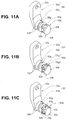
- a groove as shown in Fig. 11A, 11B or 11C may be formed to the raising base coupling portion 53d, of the raising base operation arm 53, having the flat surface portions 53f, and the raising base coupling portion 53d may be coupled to the coupling hole 54h of the raising base 54, as shown in Fig. 12A or 12B , so as to increase the cleaning performance.
- Fig. 11A one circumferential groove 53g dividing each flat surface portion 53f into two is provided at the center of the flat surface portions 53f.
- the width dimension of the circumferential groove 53g is set as appropriate taking the area of the flat surface portion 53f into account.
- Fig. 11B two circumferential grooves 53g1, 53g2 dividing each flat surface portion 53f into three are provided.
- the width dimensions of the circumferential grooves 53g1, 53g2 are the same, for example, and are set as appropriate taking the area of the flat surface portion 53f into account.
- Fig. 11A one circumferential groove 53g dividing each flat surface portion 53f into two is provided at the center of the flat surface portions 53f.
- the width dimension of the circumferential groove 53g is set as appropriate taking the area of the flat surface portion 53f into account.
- Fig. 11B two circumferential grooves 53g1, 53g2 dividing each flat surface portion 53f into three are provided.
- a plurality of orthogonal grooves 53h orthogonal to the circumferential groove 53g are provided.
- the orthogonal grooves 53h are each provided between the respective flat surface portions 53f.
- the width dimension of the orthogonal grooves 53h is set as appropriate taking the area of the flat surface portion 53f into account.
- the liquid when cleaning water or rinsing water is supplied into the raising base space 25, the liquid enters the gap between the raising base coupling portion 53d and the coupling hole 54h of the raising base 54, and after passing through the gap, the liquid flows in the circumferential groove 53g, the first circumferential groove 53g1, the second circumferential groove 53g2, or the orthogonal grooves 53h to swiftly wash out the dust or the like in the gap.
- a coupling portion 70 shown in Figs. 13A and 13B is provided between the adjacent bending pieces of the present embodiment.
- the coupling portion 70 is configured from a first coupling portion 71, and a second coupling portion 72.
- first coupling portion 71 is provided on the proximal end side of an intermediate bending piece
- second coupling portion 72 is provided on the distal end side/proximal end side of the intermediate bending piece.
- the second coupling portion 72 includes a pin hole 73.
- the first coupling portion 71 includes a pin hole 74, and a restriction hole 75.
- the restriction hole 75 includes a first abutting surface 75a, and a second abutting surface 75b.
- One side portion of a rising portion 72a of the second coupling portion 72 abuts against the first abutting surface 75a, and another side portion of the rising portion 72a of the second coupling portion 72 abuts against the second abutting surface 75b.
- a coupling pin 76 is crimped while being disposed in the pin hole 73 of the second coupling portion 72 and the pin hole 74 of the first coupling portion 71.
- the coupling pin 76 is crimped to couple adjacent intermediate bending pieces in a rotatable state.
- the rotation range of a first intermediate bending piece 77 and a second intermediate bending piece 78 which are rotatably coupled together by the coupling pin 76 is restricted by a side portion of the rising portion 72a abutting against the first abutting surface 75a or the second abutting surface 75b of the restriction hole 75.
- a proximal end corner portion 77ra of the first intermediate bending piece 77 and a distal end corner portion 78fa of the second intermediate bending piece 78 do not abut against each other and are separated from each other by a predetermined distance.
- the separation distance between the proximal end corner portion 77ra of the first intermediate bending piece 77 and the distal end corner portion 78fa of the second intermediate bending piece 78 may be set to achieve a desired non-abutting state by appropriately setting a width dimension W and an angle ⁇ of the first coupling portion 71.
- an endoscope can be realized according to which pressurized air may be supplied into a space provided in the distal end portion including the raising base, which is a space where the illumination optical system and the image pickup optical system are disposed, without increasing the diameter of the insertion section including the bending portion, and according to which dust and the like in the bending portion may be prevented from entering the space.
Abstract
Description
- The present invention relates to an endoscope having, at a distal end portion of an insertion section, a raising base for switching the direction of a treatment instrument which is guided outside from a distal end opening provided in the insertion section.
- As a medical endoscope, there is a so-called duodenoscope, which is a side-view type endoscope (hereinafter referred to as an endoscope) having an illumination lens and an objective lens arranged on a side surface on the distal end side of an insertion section.
- The endoscope is used for surgical techniques such as endoscopic retrograde cholangiopancreatography for imaging a pancreaticobiliary duct through a duodenum, or endoscopic papillotomy for removing a choledocholith (bile duct stone).
- The endoscope is provided with a treatment instrument insertion channel and a raising device.
- The treatment instrument insertion channel is a tubular body with a through hole for inserting a treatment instrument such as a contrast tube, a basket catheter, or a balloon catheter. The treatment instrument insertion channel is disposed inside an insertion section, along a longitudinal axis of the insertion section. A distal end of the treatment instrument insertion channel is connected to a distal end portion main body forming a distal end portion of the endoscope, and its proximal end is connected to a treatment instrument insertion opening provided in an operation section.
- On the other hand, the raising device is a device for switching, to a desired direction, the direction of a treatment tool which is passed through the treatment instrument insertion channel and is guided to outside from a distal end opening provided in the distal end portion main body. Generally, the raising device is configured mainly from a raising base which is rotatably disposed to the distal end portion main body, a raising base operation lever provided in the operation section, and a raising base operation wire configured to move according to operation of the raising base operation lever and to swing the raising base.
-
Japanese Patent Application Laid-Open Publication No. 8-56900 - According to the endoscope, an observation window is provided in one of left and right half portions on side surfaces of a distal end of an insertion section, and a treatment instrument raising base to be swung in the front-back direction by remote operation is provided in the other half portion. A pair of inner and outer walls which are in contact with both side surfaces of the treatment instrument raising base in the swinging range of the treatment instrument raising base are formed to the distal end of the insertion section, and a distal end of an operation wire to be remotely operated is disposed on a back side of the outer wall surface, and motion of a distal end of the operation wire is transmitted to the treatment instrument raising base by a driving force transmission member disposed penetrating the outer wall.
- That is, as shown in
Fig. 1 ofJapanese Patent Application Laid-Open Publication No. 8-56900 - Moreover, an opening portion of the raising base drive chamber is blocked in a liquid-tight manner by a sealing lid, and an insulating plastic cover is externally attached to the distal end portion main body. Furthermore, a liquid, such as a body fluid, is prevented from entering into a raising base accommodating chamber from outside by providing an O-shaped ring to the raising base drive lever.
- Also, the observation window and the illumination window are provided in a liquid-tight manner to the distal end portion main body. As a result, a liquid is prevented from entering from outside into the distal end portion main body through the observation window and the illumination window.
- However, the proximal end side of the distal end portion main body is integrally and fixedly installed to a distal end portion of a bending portion, for example. Accordingly, a space inside the bending portion and a space inside the distal end portion main body are communicated with each other. Accordingly, a signal cable extending from an image pickup apparatus is passed through the inside of the insertion section including the bending portion and the inside of an operation section and is guided to an endoscope connector. Moreover, a light guide fiber bundle is passed from the endoscope connector through the inside of the operation section and the inside of the insertion section, and is made to face the illumination window. Furthermore, the operation wire to be remotely operated is passed through the inside of the operation section and the inside of the insertion section with the distal end guided into the raising base drive chamber, and is fixedly installed to the raising base drive lever.
- Accordingly, in a case where a powder lubricant is applied to the bending portion, for example, a part of the powder may enter between the illumination window and a distal end surface of the bundle, resulting in an inconvenience such as illumination light being blocked and the amount of illumination light being reduced, for example.
- To solve such an inconvenience, it is conceivable to apply a sealing member, such as an adhesive, around the light guide fiber bundle, and to block an opening at a boundary portion between the distal end portion main body and the bending portion, and to dispose an illumination optical system in a closed space. However, in the case of forming a closed space and preventing entering of powder or the like, pressurized air for detecting water leakage is not supplied into the closed space, and it becomes difficult to discover separation of an adhesive layer between the illumination lens and the distal end portion main body or damage to the illumination lens, for example.
- Furthermore, in a case where a closed space is formed by applying a sealing member around a signal cable and blocking the opening at the boundary portion, pressurized air is not supplied into the closed space, as in the case described above, and it becomes difficult to discover separation of an adhesive layer between a lens frame and the distal end portion main body, for example.
- Additionally, in a case where a pressurization pipe reaching each closed space from the side of the operation section is provided to allow pressurization of the inside of the closed space, the number of internal components, of the endoscope, to be inserted through the insertion section is increased, and there is an inconvenience that the diameter of the insertion section including the bending portion is increased.
- Furthermore, a superb adhesive application technique of providing a hole through which pressurized air is allowed to pass, while preventing entering of dust, such as a powder, at the time of application of a sealing member requires a high skill, and is one factor that makes the endoscope expensive.
- Additionally, the problems described above apply not only to the side-view type endoscope, but also to other endoscopes which include a raising base inside a distal end portion of an insertion section.
- The present invention has been made in view of the above circumstances, and has its object to provide an endoscope according to which pressurized air may be supplied into a space where an illumination optical system and an image pickup optical system provided in a distal end portion including a raising base are disposed, without making the diameter of an insertion section including a bending portion large, and according to which dust or the like inside the bending portion may be prevented from entering the space.
- An endoscope according to an aspect of the present invention includes an operation section, an insertion section extending from the operation section, and including a distal end portion provided on a distal end side and a bending portion provided consecutively to the distal end portion, a first space provided in the distal end portion, a second space, provided in the distal end portion and sealed against a space in the bending portion, where an image pickup unit and an illumination optical system are disposed, a communication passage provided in the distal end portion, and configured to communicate between the first space and the second space, and an elongated tube member having a through hole in a longitudinal direction, and having one end portion coupled with the first space and another end portion provided inside the operation section.
-
-
Fig. 1 is a diagram describing a side-view type endoscope; -
Fig. 2 is a diagram showing a distal end portion inFig. 1 , and is a front view of a flat surface portion of the distal end portion; -
Fig. 3 is a cross-sectional diagram along a line Y3-Y3 inFig. 2 ; -
Fig. 4 is a diagram describing a configuration of a distal end portion main body; -
Fig. 5 is a diagram describing a raising base operation arm; -
Fig. 6 is a cross-sectional diagram along a line Y6-Y6 inFig. 2 ; -
Fig. 7 is a diagram including a cross-sectional diagram along a line Y7-Y7 inFig. 6 ; -
Fig. 8 is a cross-sectional diagram along a line Y8-Y8 inFig. 2 ; -
Fig. 9 is a cross-sectional diagram along a line Y9-Y9 inFig. 2 ; -
Fig. 10 is a cross-sectional diagram along a line Y10-Y10 inFig. 2 ; -
Fig. 11A is a diagram describing another example configuration of the raising base operation arm; -
Fig. 11B is a diagram describing another example configuration of the raising base operation arm; -
Fig. 11C is a diagram describing another example configuration of the raising base operation arm; -
Fig. 12A is a diagram describing a state in which a raising base coupling portion is disposed inside a coupling hole of a raising base; -
Fig. 12B is a diagram describing a state in which a raising base coupling portion is disposed inside a coupling hole of a raising base; -
Fig. 13A is a diagram describing an example configuration of a coupling portion of a bending piece; -
Fig. 13B is a diagram describing an example configuration of a coupling portion of a bending piece; -
Fig. 13C is a diagram describing an example configuration of a coupling portion of a bending piece; and -
Fig. 13D is a diagram describing an example configuration of a coupling portion of a bending piece. - Hereinafter, an embodiment of the present invention will be described with reference to the drawings.
- Note that, in each of the drawings used in the following description, the scale of display of each structural component is made different such that each structural component is large enough to be recognized in the drawing. Also, the present invention is not limited to the modes shown in the drawings with respect to the number of structural components, the shapes of the structural components, the proportion of the sizes of the structural components, and the relative positional relationship of respective structural components.
- In the following, an endoscope of the present embodiment is a side-view type endoscope.
- As shown in
Fig. 1 , an endoscope 1 is configured by including aninsertion section 2 to be inserted into a subject, anoperation section 3 provided on the proximal end side of theinsertion section 2, and auniversal cord 4 extending from theoperation section 3. - The
operation section 3 of the endoscope 1 is provided with abending operation device 11, an air/water feeding button 12, asuction button 13, a raisingbase operation lever 51 constituting a raisingdevice 50 described later, and various operation switches 14. - The operation switches 14 are a freeze switch configured to generate a freeze signal, a release switch configured to generate a release signal at a time of performing photographing, an observation mode switching switch configured to issue an instruction to switch an observation mode, and the like.
- The
operation section 3 is provided with a treatmentinstrument insertion opening 15 for introducing a treatment instrument (not shown) into a living body. One end side of a treatmentinstrument insertion channel 16 is connected to the treatmentinstrument insertion opening 15, and another end of the treatmentinstrument insertion channel 16 is connected to a distal end portion main body (see thereference sign 20 inFig. 8 ), described later, constituting adistal end portion 5 of theinsertion section 2. The treatmentinstrument insertion channel 16 is a flexible tubular body, and is disposed inside theinsertion section 2, along a longitudinal axis of theinsertion section 2. - The
reference sign 10 is a tube member, and is a flexible resin tube having a longitudinal through hole. Thetube member 10 is a dual-purpose tubular body described later, and is disposed inserted in theinsertion section 2 along the longitudinal axis of theinsertion section 2. A proximal end surface of thetube member 10 is provided inside theoperation section 3, and a raisingbase operation wire 52 constituting the raisingdevice 50 is inserted through thetube member 10. - A mid-portion of the raising
base operation wire 52 is disposed inside thetube member 10. A distal end of the raisingbase operation wire 52 is guided out of thetube member 10, and is connected to a raising base operation arm (see thereference sign 53 inFig. 5 ) constituting the raisingdevice 50. A proximal end of the raisingbase operation wire 52 extends from a proximal end of thetube member 10, and is connected to the raisingbase operation lever 51 through a link mechanism or the like, not shown. - The
insertion section 2 extending from theoperation section 3 is configured from adistal end portion 5, a bendingportion 6, and aflexible tube portion 7 which are provided consecutively in this order from the distal end side. - For example, the
flexible tube portion 7 is configured by including a spiral tube, a mesh tube covering the spiral tube, and a heat shrinkable tube forming an outermost layer, which are not shown. The bendingportion 6 is configured by including a set of bending pieces (see thereference sign 6a inFig. 3 ) which are configured to bend in four direction of up, down, left, and right, a metal mesh tube (see thereference sign 6b inFig. 3 ) covering the set of bendingpieces 6a, and a bending rubber (see thereference sign 6c inFig. 3 ), which is an outer skin. - The reference sign 6af in
Fig. 3 is a distal end bending piece, the reference sign 6a1 is a first intermediate bending piece, and the bending pieces are a part of a plurality of bending pieces constituting the set of bending pieces. - The bending
portion 6 is configured to be bent in an upward direction or a downward direction by rotation operation of an upward/downward bending knob 11a of thebending operation device 11 provided in theoperation section 3, and to be bent in a left/right direction by rotation operation of a left/right bending knob 11b. - A
flat surface portion 5F is provided on one side surface, for example, an upper side surface, of thedistal end portion 5 of the endoscope 1. - The upper side surface is a surface corresponding to the upward bending direction of the bending
portion 6. - As shown in
Figs. 2 and 3 , for example, thedistal end portion 5 is configured by including a distal end portionmain body 20, and acover member 30. - The distal end portion
main body 20 is a rigid member of metal, for example, and thecover member 30 is a rigid member of resin, for example. - The
cover member 30 is integrally fixed, in a liquid-tight manner, to the distal end portionmain body 20 excluding theflat surface portion 5F and the proximal end portion side of the distal end portionmain body 20. - As shown in
Fig. 4 , the distal end portionmain body 20 is configured by including aflat surface 21 mainly constituting theflat surface portion 5F, anillumination window hole 22 and anobservation window hole 23 provided as openings at predetermined positions on theflat surface 21, a recessedportion 24 for optics, a raisingbase space 25, and anarm accommodating chamber 26. - The raising
base space 25 is a recessed portion provided at a center portion of the distal end portionmain body 20, and is a groove with a predetermined depth from a distal end surface of the distal end portionmain body 20, and includeswall surfaces longitudinal axis 20a. A raisingbase 54 constituting the raisingdevice 50 is to be rotatably disposed in the raisingbase space 25. - The raising
device 50 is mainly configured from the raisingbase operation lever 51, the raisingbase operation wire 52, the raisingbase operation arm 53, and the raisingbase 54, which are described above. The raisingbase operation lever 51, the raisingbase operation arm 53, and the raisingbase 54 are rigid members, and are of metal or resin. - The recessed
portion 24 for optics is a groove that is formed along thelongitudinal axis 20a. The recessedportion 24 for optics is provided on the left side of the raisingbase space 25 when the distal end portionmain body 20 is seen from the distal end surface side. Theillumination window hole 22 and theobservation window hole 23 are formed in a manner communicating with the recessedportion 24 for optics. - The
arm accommodating chamber 26 is a recessed portion provided on the right side of the raisingbase space 25 when the distal end portionmain body 20 is seen from the distal end surface side, and anopening 26m of thearm accommodating chamber 26 is formed on the right side surface. - The
arm accommodating chamber 26 is configured by including a recessedportion 27 for an arm and a recessedportion 28 for a fixing tool. - An arm
main body 53a of the raisingbase operation arm 53 shown inFig. 5 is to be disposed in the recessedportion 27 for an arm. For this purpose, an opening which is ashaft hole 27h shown inFig. 4 is formed to a bottom surface of the recessedportion 27 for an arm. Theshaft hole 27h is a through hole for communicating between the recessedportion 27 for an arm and the raisingbase space 25, and ashaft portion 53b of the raisingbase operation arm 53 is rotatably disposed in theshaft hole 27h. - The
reference sign 60a is afirst opening 60a of acommunication passage 60. Additionally, as shown inFig. 10 described later, thecommunication passage 60 is a through hole having thefirst opening 60a at the recessedportion 27 for an arm and asecond opening 60b at the recessedportion 24 for optics. - As shown in
Fig. 5 , the raisingbase operation arm 53 is L-shaped, and is configured by including the armmain body 53a, and theshaft portion 53b. Awire fixing portion 53c, which is a through hole, in which a distal end portion of the raisingbase operation wire 52 is to be fixedly installed is provided at an end surface side of the armmain body 53a. - The raising
base operation wire 52 is guided to the recessedportion 27 for an arm through a throughhole 62 formed to a pipe-shapedfixing tool 61 that is fixedly installed inside the recessedportion 28 for a fixing tool, as shown inFigs. 6 and7 . Amain body portion 63 of the fixingtool 61 is integrally fixed inside the recessedportion 28 for a fixing tool by soldering, adhesion, screw fastening or the like. - A proximal end portion of the fixing
tool 61 is configured as a tubemember coupling portion 64 to which a distal end portion of thetube member 10 is to be fixedly installed. The tubemember coupling portion 64 protrudes into an inner space of the bendingportion 6 by a predetermined amount from a proximal end surface of the distal end portionmain body 20. - The
tube member 10 is integrally fixed to the fixingtool 61 by an adhesive 65 after being externally fitted to the tubemember coupling portion 64. The adhesive 65 is applied to around the distal end portion of thetube member 10 and the proximal end surface of the distal end portionmain body 20. As a result, an opening on the proximal end side of the recessedportion 28 for a fixing tool in which thefixing tool 61 is disposed is sealed against an inner space of the bendingportion 6 by the adhesive 65. - Additionally, as the method of sealing, there is also a method of filling the gap between the
main body portion 63 and the recessedportion 28 for a fixing tool by an adhesive, a sealant or the like. In this case, thetube member 10 and the tubemember coupling portion 64 may be fixed by being tied together by a string member such as a fishing gut, instead of using an adhesive. - The shape of the through
hole 62, of the end portion on the side of the tubemember coupling portion 64, is tapered, and the inner diameter which is great on the proximal end opening side is reduced toward a mid-portion. According to this configuration, the distal end of the raisingbase operation wire 52 guided out of thetube member 10 is smoothly inserted into the throughhole 62, and is guided to the recessedportion 27 for an arm after passing through the throughhole 62. - The distal end of the raising
base operation wire 52 is passed through the inside of aguide hole 53e and is disposed at thewire fixing portion 53c. The distal end of the raisingbase operation wire 52 is fixed, by a solder applied to thewire fixing portion 53c or by brazing, for example, in such a way that it will not fall out of the armmain body 53a. - Additionally, as shown in
Fig. 6 , theguide hole 53e is substantially fan-shaped, and is formed to gradually spread out from thewire fixing portion 53c toward one side surface. Thereference sign 66 is a dual-purpose tube protection member, which is a coil member for protecting thetube member 10, and is disposed on the outer circumferential side of thetube member 10. A distal end portion of the dual-purposetube protection member 66 is fixedly installed near the proximal end surface of the distal end portionmain body 20 by the adhesive 65. - Furthermore, an outer surface of the dual-purpose
tube protection member 66 is covered with atube protection member 67. Thetube protection member 67 prevents the dual-purposetube protection member 66 from being damaged by coming into contact with other internal components at the time of bending operation of the bendingportion 6, by covering the dual-purposetube protection member 66 at least in the range of the bending portion 6 (seeFig. 7 ). - The cross-section of the
shaft portion 53b shown inFig. 5 is circular, and theshaft portion 53b is rotatably disposed in theshaft hole 27h. As shown inFig. 9 , an O-shapedring 55 is provided on theshaft portion 53b. The O-shapedring 55 comes into close contact with the entire inner circumference of theshaft hole 27h to maintain liquid tightness. - The O-shaped
ring 55 is disposed in acircumferential groove 55g shown inFig. 5 . The side more to the end surface than thecircumferential groove 55g of theshaft portion 53b is a raisingbase coupling portion 53d. For example, threeflat surface portions 53f serving as rotation detents are provided at regular intervals on the outer circumferential surface of the raisingbase coupling portion 53d. Thereference sign 53h is a detent hole, and the distal end portion side of a locking pin is disposed in thedetent hole 53h. - As shown in
Fig. 9 , in a state of being disposed inside theshaft hole 27h, theshaft portion 53b protrudes from thefirst wall surface 25a into the raisingbase space 25. Then, the raisingbase coupling portion 53d is disposed inside acoupling hole 54h of the raisingbase 54 disposed in the raisingbase space 25. - As shown in
Fig. 8 , flat abuttingsurfaces 54f are provided in thecoupling hole 54h in relation to theflat surface portions 53f. Also, a hole (not shown) for a locking pin in which the locking pin is to be disposed is formed near thecoupling hole 54h. In a coupled state, the locking pin, not shown, is fixedly installed in the hole for a locking pin and the detent hole. - As a result, as shown in
Figs. 8 and9 , the raisingbase coupling portion 53d protruding in the raisingbase space 25 is fixedly installed in thecoupling hole 54h, which is a through hole provided in the raisingbase 54, and the raisingbase operation arm 53 and the raisingbase 54 are integrally configured. - Moreover, as shown in
Fig. 8 , a distal end portion of the treatmentinstrument insertion channel 16 into which a treatment instrument or the like is to be inserted is fixedly installed in a proximal end portion of achannel pipe sleeve 19 which is fixedly installed in the distal end portionmain body 20. Thechannel pipe sleeve 19 is fixedly installed in apipe sleeve hole 20h, which is a through hole formed at a predetermined position along the longitudinal axis of the distal end portionmain body 20. Thepipe sleeve hole 20h does not reach thecommunication passage 60, and is provided with an opening on the side of the raisingbase space 25 while taking into account the position where the raisingbase 54 is to be disposed. - As shown in
Figs. 6 and9 , theopening 26m of thearm accommodating chamber 26 is covered and blocked by thecover member 30 after being sealed by alid member 29. Also, the O-shapedring 55 provided on theshaft portion 53b is in close contact with the entire inner circumference of theshaft hole 27h while maintaining liquid tightness. Moreover, as shown inFig. 7 , the opening, on the proximal end side, of the recessedportion 28 for a fixing tool where the fixingtool 61 is disposed and the distal end portion of thetube member 10 are sealed against the inner space of the bendingportion 6 by the adhesive 65. Also, the proximal end surface of thetube member 10 is provided inside theoperation section 3. - As a result, the
arm accommodating chamber 26 of the distal end portionmain body 20 is provided, in thedistal end portion 5, as a first closed space S1 which is sealed against the inner space of the bendingportion 6. - As shown in
Figs. 2 and 3 , anillumination lens 81, which is an illumination window constituting an illuminationoptical system 8, is fixed to theillumination window hole 22 in a liquid-tight manner. Also, anobservation lens 91, which is an observation window constituting an observationoptical system 9, is fixed to theobservation window hole 23 in a liquid-tight manner. Thereference sign 17 is a nozzle. A fluid, such as water or air, is injected from thenozzle 17 toward theillumination lens 81 and theobservation lens 91. Thereference sign 18 is an air/water feeding pipe. - The illumination
optical system 8 is configured by mainly including theillumination lens 81, and a lightguide fiber bundle 82. A distal end surface of the lightguide fiber bundle 82 faces a proximal end surface of theillumination lens 81. A proximal end portion of the lightguide fiber bundle 82 extends from an opening of the recessedportion 24 for optics, on the proximal end side, and is disposed at a predetermined position inside an endoscope connector (not shown) after passing through the insides of the insertion section, the operation section, and the universal cord. - The observation
optical system 9 is configured by mainly including theobservation lens 91, animage pickup apparatus 92, and asignal cable 93. Theimage pickup apparatus 92 is configured by including a plurality of optical lenses, an image pickup device, and a substrate on which electronic components are mounted, which are not shown. - The
observation lens 91 constitutes the distal end side of theimage pickup apparatus 92. Like the lightguide fiber bundle 82, a proximal end portion of thesignal cable 93 extends from the opening of the recessedportion 24 for optics, on the proximal end side, and is disposed at a predetermined position inside the endoscope connector after passing through the insides of the insertion section, the operation section, and the universal cord. - The
reference sign 60b is the second opening of thecommunication passage 60. Thereference sign 5M is a distal end portion constituent member, and is integrally fixed inside the recessedportion 24 for optics by an adhesive or the like, as shown inFigs. 3 and9 . An opticalsystem accommodating portion 5a and an image pickupapparatus support portion 5b are provided in the distal endportion constituent member 5M. - A light
guide arrangement portion 5c where the lightguide fiber bundle 82 is to be disposed, and an image pickupapparatus accommodating space 5d where theimage pickup apparatus 92 is to be disposed are provided in the opticalsystem accommodating portion 5a. As shown inFigs. 9 and 10 , the lightguide fiber bundle 82 is disposed along a bottom surface of the lightguide arrangement portion 5c. Theimage pickup apparatus 92 is disposed in the image pickupapparatus accommodating space 5d in a manner separated from the lightguide fiber bundle 82. - As shown in
Figs. 3 and9 , openings on the distal end side and the lower side of the recessedportion 24 for optics where the distal endportion constituent member 5M is provided are covered and blocked by thecover member 30. Also, the opening on the proximal end side of the recessedportion 24 for optics is coated and blocked by a sealingmember 100 in a state in which the distal endportion constituent member 5M is provided. The sealingmember 100 fills the surrounding of the lightguide fiber bundle 82 extending from the opening on the proximal end side of the recessedportion 24 for optics, the surrounding of thesignal cable 93, a proximal end surface of the distal endportion constituent member 5M, and an inner surface of thecover member 30. - As a result, the recessed
portion 24 for optics of the distal end portionmain body 20 is provided, in thedistal end portion 5, as a second closed space S2 which is sealed against the inner space of the bendingportion 6. - Moreover, as shown in
Fig. 10 , the first closed space S1 and the second closed space S2 are communicated with each other by thecommunication passage 60. - A working of the endoscope configured in the above manner will be described. For example, when examining the inside of a bile duct, a surgeon first inserts the
distal end portion 5 of theinsertion section 2 of the endoscope 1 inside the duodenum. The surgeon then inserts a treatment instrument into the treatmentinstrument insertion channel 16 through the treatmentinstrument insertion opening 15 provided in theoperation section 3 of the endoscope 1. The surgeon causes the treatment instrument to pass through thechannel 16 and above the raisingbase 54, and to protrude to outside thedistal end portion 5 by a predetermined amount. - Here, the surgeon operates the raising
base operation lever 51. The raisingbase operation wire 52 inside thetube member 10 is moved according to the operation of thelever 51. Then, according to the movement of the raisingbase operation wire 52, the armmain body 53a of the raisingbase operation arm 53 moves inside the first closed space S1, around theshaft portion 53b, from a state shown by the solid line inFig. 6 to a state shown by the dotted line. - Also, the raising
base 54, which is integrally fixed to the raisingbase operation arm 53, is rotated in the same manner inside the raisingbase space 25 according to the rotation of the armmain body 53a, thereby changing the direction of the treatment instrument, and the treatment instrument is made to face the bile duct at a distal end, for example. The surgeon inserts the treatment instrument into the bile duct, and performs examination or the like. - After the examination, the surgeon removes the endoscope 1 from the living body.
- After the examination, the endoscope is cleaned and disinfected. At the time of cleaning/disinfecting, water leakage detection is performed to investigate whether a hole is opened to the
insertion section 2 or the like. That is, pressurized air is supplied from the endoscope connector (not shown) of the endoscope into theuniversal cord 4, theoperation section 3, and theinsertion section 2. In the water leakage detection, the pressurized air is supplied from the opening at the proximal end of thetube member 10 through the inside of 10 into the first closed space S1 provided in thedistal end portion 5, and is also supplied through thecommunication passage 60 into the second closed space S2 provided in thedistal end portion 5. - As a result, in addition to investigation of opening of a hole to the
insertion section 2, investigation may be reliably performed in relation to separation of an adhesive layer between theillumination lens 81 and the distal end portionmain body 20, or presence/absence of damage to theillumination lens 81, or separation of an adhesive between the lens frame of theobservation lens 91 and the distal end portion main body, presence/absence of damage, or the like. - As described above, the first closed space S 1 and the second closed space S2, which are sealed against the inner space of the bending
portion 6, are provided inside thedistal end portion 5, and the first closed space S1 and the second closed space S2 are communicated by thecommunication passage 60. In addition, one end of thetube member 10 is communicated with the first closed space S 1, and the proximal end is disposed inside the operation section. - According to the configuration, the
tube member 10 serves as both a guide tube through which the raisingbase operation wire 52 is to be inserted and a fluid tube configured to supply pressurized air. As a result, an inconvenience of a powder lubricant or the like applied to a set of bending pieces constituting the bendingportion 6 entering the first closed space S 1 and the second closed space S2 may be solved without increasing the diameter of theinsertion section 2, or changing the configuration of the raisingdevice 50. Moreover, at the time of water leakage detection, pressurized air may be supplied into the first closed space S 1 and the second closed space S2 so that detection of water leakage inside theinsertion section 2 may be performed more reliably. - Additionally, the endoscope 1 described above is a side-view type endoscope. However, the endoscope is not limited to the side-view type endoscope, and is applicable as a front-view type endoscope having the raising base provided in the treatment instrument insertion channel.
- Furthermore, the
tube member 10 of the embodiment described above is a flexible resin tube, and has a longitudinal through hole. Thetube member 10 is not limited to a resin tube having a longitudinal through hole, and it may alternatively be a resin tube having a plurality of small through holes which communicate between the inside of a longitudinal through hole and the outside of the outer circumferential surface, for example. By using the resin tube with a plurality of small holes as thetube member 10, moisture inside the second closed space S2 may be released to the entire region in the inner space of the endoscope 1 through thecommunication passage 60, the first closed space S1, and the small through holes of thetube member 10, and thelenses - Furthermore, a configuration is also possible where only the resin tube is not provided, or where the resin tube and the protection tube are not provided, or where only the protection tube is not provided. In such cases, there is a possibility of a lubricant entering from the gap of the coil. However, because the gap of the coil is sufficiently small, entering of the lubricant may be sufficiently prevented. The
tube member 10 may be made thinner by adopting such a configuration. - Furthermore, also in a case where the first space is not completely sealed, entering of a lubricant from the bending tube portion into the second space may be made difficult by sufficiently narrowing the communication passage or by changing the direction of the channel from a long axis direction to a substantially perpendicular direction.
- Furthermore, a groove as shown in
Fig. 11A, 11B or 11C may be formed to the raisingbase coupling portion 53d, of the raisingbase operation arm 53, having theflat surface portions 53f, and the raisingbase coupling portion 53d may be coupled to thecoupling hole 54h of the raisingbase 54, as shown inFig. 12A or 12B , so as to increase the cleaning performance. - In
Fig. 11A , onecircumferential groove 53g dividing eachflat surface portion 53f into two is provided at the center of theflat surface portions 53f. The width dimension of thecircumferential groove 53g is set as appropriate taking the area of theflat surface portion 53f into account. InFig. 11B , two circumferential grooves 53g1, 53g2 dividing eachflat surface portion 53f into three are provided. The width dimensions of the circumferential grooves 53g1, 53g2 are the same, for example, and are set as appropriate taking the area of theflat surface portion 53f into account. InFig. 11C , in addition to the onecircumferential groove 53g dividing eachflat surface portion 53f into two, a plurality oforthogonal grooves 53h orthogonal to thecircumferential groove 53g are provided. Theorthogonal grooves 53h are each provided between the respectiveflat surface portions 53f. The width dimension of theorthogonal grooves 53h is set as appropriate taking the area of theflat surface portion 53f into account. - According to the configuration described above, as shown in
Figs. 12A and 12B , when cleaning water or rinsing water is supplied into the raisingbase space 25, the liquid enters the gap between the raisingbase coupling portion 53d and thecoupling hole 54h of the raisingbase 54, and after passing through the gap, the liquid flows in thecircumferential groove 53g, the first circumferential groove 53g1, the second circumferential groove 53g2, or theorthogonal grooves 53h to swiftly wash out the dust or the like in the gap. - In the case of a configuration where facing end portions of adjacent bending pieces abut each other when the bending portion is bent, there is a possibility of an internal component of the endoscope or a mesh tube being caught between the bending pieces. Accordingly, a
coupling portion 70 shown inFigs. 13A and 13B is provided between the adjacent bending pieces of the present embodiment. Thecoupling portion 70 is configured from afirst coupling portion 71, and asecond coupling portion 72. - For example, the
first coupling portion 71 is provided on the proximal end side of an intermediate bending piece, and thesecond coupling portion 72 is provided on the distal end side/proximal end side of the intermediate bending piece. Thesecond coupling portion 72 includes apin hole 73. - For its part, the
first coupling portion 71 includes apin hole 74, and arestriction hole 75. Therestriction hole 75 includes a firstabutting surface 75a, and a secondabutting surface 75b. One side portion of a risingportion 72a of thesecond coupling portion 72 abuts against the firstabutting surface 75a, and another side portion of the risingportion 72a of thesecond coupling portion 72 abuts against the secondabutting surface 75b. - As shown in
Fig. 13C , acoupling pin 76 is crimped while being disposed in thepin hole 73 of thesecond coupling portion 72 and thepin hole 74 of thefirst coupling portion 71. Thecoupling pin 76 is crimped to couple adjacent intermediate bending pieces in a rotatable state. - The rotation range of a first
intermediate bending piece 77 and a secondintermediate bending piece 78 which are rotatably coupled together by thecoupling pin 76 is restricted by a side portion of the risingportion 72a abutting against the firstabutting surface 75a or the secondabutting surface 75b of therestriction hole 75. - Specifically, in a state in which one side portion of the rising
portion 72a is abutting against the firstabutting surface 75a of therestriction hole 75, a proximal end corner portion 77ra of the firstintermediate bending piece 77 and a distal end corner portion 78fa of the secondintermediate bending piece 78 do not abut against each other and are separated from each other by a predetermined distance. As a result, an inconvenience of an internal component of the endoscope or a mesh tube getting caught between the adjacent bending pieces may be prevented. - Note that the separation distance between the proximal end corner portion 77ra of the first
intermediate bending piece 77 and the distal end corner portion 78fa of the secondintermediate bending piece 78 may be set to achieve a desired non-abutting state by appropriately setting a width dimension W and an angle θ of thefirst coupling portion 71. - Note that the present invention is not limited to the embodiment described above, and may be subjected to various changes and applications within the scope of the invention.
- According to the present invention, an endoscope can be realized according to which pressurized air may be supplied into a space provided in the distal end portion including the raising base, which is a space where the illumination optical system and the image pickup optical system are disposed, without increasing the diameter of the insertion section including the bending portion, and according to which dust and the like in the bending portion may be prevented from entering the space.
- The present application is filed claiming priority based on Japanese Patent Application No.
2014-159773 filed in Japan on August 5, 2014
Claims (7)
- An endoscope comprising:an operation section;an insertion section extending from the operation section, and including a distal end portion provided on a distal end side and a bending portion provided consecutively to the distal end portion;a first space provided in the distal end portion;a second space, provided in the distal end portion and sealed against a space in the bending portion, where an image pickup unit and an illumination optical system are disposed;a communication passage provided in the distal end portion, and configured to communicate between the first space and the second space; andan elongated tube member having a through hole in a longitudinal direction, and having one end portion coupled with the first space and another end portion provided inside the operation section.
- The endoscope according to claim 1, wherein the first space is sealed against the space in the bending portion.
- The endoscope according to claim 1, wherein the first space is an arm accommodating chamber where a raising base operation arm is disposed, the raising base operation arm being configured to swing a raising base constituting a raising device provided in the distal end portion.
- The endoscope according to claim 3, wherein the through hole in the longitudinal direction of the tube member serves both as a wire insertion channel in which a raising base operation wire, constituting the raising device, a distal end of which is connected to the raising base operation arm, is inserted and disposed, and as a supply channel configured to supply pressurized air into the first space and into the second space through the communication passage.
- The endoscope according to claim 1, wherein the tube member is formed only by a coil spring.
- The endoscope according to claim 1, wherein a space volume of the communication passage is set smaller than volumes of the first space and the second space.
- The endoscope according to claim 1, wherein the communication passage is formed substantially perpendicularly to a long axis direction of the insertion section.
Applications Claiming Priority (2)
| Application Number | Priority Date | Filing Date | Title |
|---|---|---|---|
| JP2014159773 | 2014-08-05 | ||
| PCT/JP2015/060191 WO2016021231A1 (en) | 2014-08-05 | 2015-03-31 | Endoscope |
Publications (2)
| Publication Number | Publication Date |
|---|---|
| EP3097843A1 true EP3097843A1 (en) | 2016-11-30 |
| EP3097843A4 EP3097843A4 (en) | 2017-10-25 |
Family
ID=55263516
Family Applications (1)
| Application Number | Title | Priority Date | Filing Date |
|---|---|---|---|
| EP15830618.3A Withdrawn EP3097843A4 (en) | 2014-08-05 | 2015-03-31 | Endoscope |
Country Status (5)
| Country | Link |
|---|---|
| US (1) | US10321806B2 (en) |
| EP (1) | EP3097843A4 (en) |
| JP (1) | JP5948510B1 (en) |
| CN (1) | CN106061359B (en) |
| WO (1) | WO2016021231A1 (en) |
Cited By (2)
| Publication number | Priority date | Publication date | Assignee | Title |
|---|---|---|---|---|
| US11395581B2 (en) | 2016-07-11 | 2022-07-26 | Hoya Corporation | Endoscope having swinging elevator |
| US11925324B2 (en) | 2018-01-31 | 2024-03-12 | Olympus Corporation | Insertion apparatus and endoscope |
Families Citing this family (15)
| Publication number | Priority date | Publication date | Assignee | Title |
|---|---|---|---|---|
| JP6110828B2 (en) * | 2014-09-30 | 2017-04-05 | 富士フイルム株式会社 | Endoscope device |
| JP6110829B2 (en) | 2014-09-30 | 2017-04-05 | 富士フイルム株式会社 | Endoscope device |
| JP6173287B2 (en) * | 2014-09-30 | 2017-08-02 | 富士フイルム株式会社 | Endoscope device |
| JP6249978B2 (en) * | 2015-03-20 | 2017-12-20 | 富士フイルム株式会社 | Endoscope |
| CN106793925B (en) * | 2015-06-08 | 2018-09-11 | 奥林巴斯株式会社 | Endoscope |
| JP6542374B2 (en) * | 2015-09-02 | 2019-07-10 | 富士フイルム株式会社 | Endoscope and treatment tool rising mechanism |
| WO2018016487A1 (en) * | 2016-07-19 | 2018-01-25 | Hoya株式会社 | Endoscopic cap, endoscope, and production method for endoscopic cap |
| JPWO2018079792A1 (en) * | 2016-10-28 | 2019-09-19 | オリンパス株式会社 | Endoscope and endoscope head cleaning method |
| JP6704872B2 (en) * | 2017-03-31 | 2020-06-03 | 富士フイルム株式会社 | Endoscope and method of mounting optical system in endoscope |
| JP6522087B2 (en) * | 2017-11-21 | 2019-05-29 | 富士フイルム株式会社 | Endoscope |
| US10932650B2 (en) * | 2017-11-27 | 2021-03-02 | Karl Storz Imaging, Inc. | Medical scope button system providing user feedback without the need for direct sight or activation test |
| WO2019138440A1 (en) * | 2018-01-09 | 2019-07-18 | オリンパス株式会社 | Imaging device, endoscope, and manufacturing method for imaging device |
| CN113613542A (en) * | 2019-01-24 | 2021-11-05 | 诺亚医疗集团公司 | Disposable device with integrated vision capabilities |
| CN114533209A (en) * | 2020-11-26 | 2022-05-27 | 微创优通医疗科技(上海)有限公司 | Medical catheter and medical device comprising same |
| WO2023148901A1 (en) * | 2022-02-03 | 2023-08-10 | オリンパスメディカルシステムズ株式会社 | Endoscope and tip body |
Family Cites Families (16)
| Publication number | Priority date | Publication date | Assignee | Title |
|---|---|---|---|---|
| DE2424749B2 (en) * | 1973-05-23 | 1976-10-21 | Olympus Optical Co. Ltd., Tokio | ENDOSCOPE WITH A CHANNEL FOR INSERTING A FORCEPS AND SUCTIONING A LIQUID SUBSTANCE |
| JPH0629911B2 (en) * | 1985-05-07 | 1994-04-20 | 旭光学工業株式会社 | End tip structure of endoscope |
| US5573494A (en) * | 1993-02-23 | 1996-11-12 | Olympus Optical Co., Ltd. | Endoscope cover-sheathed endoscope in which an endoscope-cover coverable endoscope to be sheathed with an endoscope cover is structured to shut out water tightly |
| JP3527561B2 (en) | 1994-06-13 | 2004-05-17 | ペンタックス株式会社 | Endoscope |
| JP3186961B2 (en) * | 1995-11-17 | 2001-07-11 | 富士写真光機株式会社 | Electronic endoscope tip structure |
| JP2000107120A (en) * | 1998-08-07 | 2000-04-18 | Olympus Optical Co Ltd | Endoscope |
| US6547721B1 (en) * | 1998-08-07 | 2003-04-15 | Olympus Optical Co., Ltd. | Endoscope capable of being autoclaved |
| JP3956212B2 (en) * | 2002-10-23 | 2007-08-08 | フジノン株式会社 | The tip of a side-viewing endoscope |
| US6878107B2 (en) * | 2002-10-23 | 2005-04-12 | Fujinon Corporation | End of side-looking endoscope |
| ES2409160T3 (en) * | 2004-03-23 | 2013-06-25 | Boston Scientific Limited | Live View System |
| JP2007136044A (en) * | 2005-11-22 | 2007-06-07 | Fujinon Corp | Treater standing-up device for endoscope |
| JP4970877B2 (en) * | 2006-05-17 | 2012-07-11 | オリンパスメディカルシステムズ株式会社 | Endoscope |
| US9591965B2 (en) * | 2007-04-10 | 2017-03-14 | Boston Scientific Scimed, Inc. | Endoscopes including distal chamber and related methods of use |
| US9125582B2 (en) * | 2008-12-10 | 2015-09-08 | Ambu A/S | Endoscope having a camera housing and method for making a camera housing |
| EP2446805A4 (en) * | 2010-05-28 | 2012-05-30 | Olympus Medical Systems Corp | Endoscope |
| US10244927B2 (en) * | 2011-12-29 | 2019-04-02 | Cook Medical Technologies Llc | Space-optimized visualization catheter with camera train holder |
-
2015
- 2015-03-31 EP EP15830618.3A patent/EP3097843A4/en not_active Withdrawn
- 2015-03-31 WO PCT/JP2015/060191 patent/WO2016021231A1/en active Application Filing
- 2015-03-31 CN CN201580011273.9A patent/CN106061359B/en active Active
- 2015-03-31 JP JP2015554925A patent/JP5948510B1/en active Active
-
2016
- 2016-08-29 US US15/249,922 patent/US10321806B2/en active Active
Cited By (3)
| Publication number | Priority date | Publication date | Assignee | Title |
|---|---|---|---|---|
| US11395581B2 (en) | 2016-07-11 | 2022-07-26 | Hoya Corporation | Endoscope having swinging elevator |
| US11857163B2 (en) | 2016-07-11 | 2024-01-02 | Hoya Corporation | Endoscope having swinging elevator |
| US11925324B2 (en) | 2018-01-31 | 2024-03-12 | Olympus Corporation | Insertion apparatus and endoscope |
Also Published As
| Publication number | Publication date |
|---|---|
| EP3097843A4 (en) | 2017-10-25 |
| WO2016021231A1 (en) | 2016-02-11 |
| CN106061359B (en) | 2018-04-13 |
| US20160367114A1 (en) | 2016-12-22 |
| CN106061359A (en) | 2016-10-26 |
| US10321806B2 (en) | 2019-06-18 |
| JP5948510B1 (en) | 2016-07-06 |
| JPWO2016021231A1 (en) | 2017-04-27 |
Similar Documents
| Publication | Publication Date | Title |
|---|---|---|
| EP3097843A1 (en) | Endoscope | |
| US8702595B2 (en) | Insertion instrument endoscope | |
| US10010242B2 (en) | Endoscope | |
| US9521948B2 (en) | Endoscope | |
| JP3965170B2 (en) | Endoscope | |
| US10028642B2 (en) | Endoscope | |
| KR102110352B1 (en) | Endoscope with a detachable probe | |
| US8485965B2 (en) | Endoscope main body and endoscope | |
| CN108685555B (en) | Endoscope and method for mounting optical system in endoscope | |
| JP6250254B1 (en) | Instrument insertion aid | |
| WO2014192386A1 (en) | Endoscope | |
| US11363940B2 (en) | Endoscope | |
| CN104582558A (en) | Endoscope | |
| EP2923631B1 (en) | Endoscope insertion portion and endoscope | |
| WO2021106830A1 (en) | Endoscope | |
| JP6049950B2 (en) | Endoscope | |
| CN108882830A (en) | Endoscope | |
| CN114727750A (en) | Endoscope with a detachable handle | |
| KR102090363B1 (en) | Flexible mechanism | |
| JP5974207B2 (en) | Enclosure water-tight mechanism, endoscope | |
| JP2018171257A (en) | Ultrasonic endoscope and hood for ultrasonic endoscope | |
| US20210059505A1 (en) | Endoscope bonding structure and endoscope | |
| WO2021075262A1 (en) | Endoscope | |
| JP2014230673A (en) | Distal end structure of endoscope | |
| JP2014000207A (en) | Endoscope system |
Legal Events
| Date | Code | Title | Description |
|---|---|---|---|
| PUAI | Public reference made under article 153(3) epc to a published international application that has entered the european phase |
Free format text: ORIGINAL CODE: 0009012 |
|
| STAA | Information on the status of an ep patent application or granted ep patent |
Free format text: STATUS: REQUEST FOR EXAMINATION WAS MADE |
|
| 17P | Request for examination filed |
Effective date: 20160825 |
|
| AK | Designated contracting states |
Kind code of ref document: A1 Designated state(s): AL AT BE BG CH CY CZ DE DK EE ES FI FR GB GR HR HU IE IS IT LI LT LU LV MC MK MT NL NO PL PT RO RS SE SI SK SM TR |
|
| AX | Request for extension of the european patent |
Extension state: BA ME |
|
| A4 | Supplementary search report drawn up and despatched |
Effective date: 20170922 |
|
| RIC1 | Information provided on ipc code assigned before grant |
Ipc: G02B 23/24 20060101ALI20170918BHEP Ipc: A61B 1/00 20060101AFI20170918BHEP |
|
| DAV | Request for validation of the european patent (deleted) | ||
| DAX | Request for extension of the european patent (deleted) | ||
| STAA | Information on the status of an ep patent application or granted ep patent |
Free format text: STATUS: REQUEST FOR EXAMINATION WAS MADE |
|
| STAA | Information on the status of an ep patent application or granted ep patent |
Free format text: STATUS: THE APPLICATION IS DEEMED TO BE WITHDRAWN |
|
| 18D | Application deemed to be withdrawn |
Effective date: 20201001 |