EP3097799A1 - Battery assembly for electronic cigarette, electronic cigarette and control method therefor - Google Patents
Battery assembly for electronic cigarette, electronic cigarette and control method therefor Download PDFInfo
- Publication number
- EP3097799A1 EP3097799A1 EP14879357.3A EP14879357A EP3097799A1 EP 3097799 A1 EP3097799 A1 EP 3097799A1 EP 14879357 A EP14879357 A EP 14879357A EP 3097799 A1 EP3097799 A1 EP 3097799A1
- Authority
- EP
- European Patent Office
- Prior art keywords
- heating wire
- electronic cigarette
- battery
- electric heating
- assembly
- Prior art date
- Legal status (The legal status is an assumption and is not a legal conclusion. Google has not performed a legal analysis and makes no representation as to the accuracy of the status listed.)
- Withdrawn
Links
Images


Classifications
-
- H—ELECTRICITY
- H01—ELECTRIC ELEMENTS
- H01M—PROCESSES OR MEANS, e.g. BATTERIES, FOR THE DIRECT CONVERSION OF CHEMICAL ENERGY INTO ELECTRICAL ENERGY
- H01M10/00—Secondary cells; Manufacture thereof
- H01M10/42—Methods or arrangements for servicing or maintenance of secondary cells or secondary half-cells
- H01M10/425—Structural combination with electronic components, e.g. electronic circuits integrated to the outside of the casing
- H01M10/4257—Smart batteries, e.g. electronic circuits inside the housing of the cells or batteries
-
- A—HUMAN NECESSITIES
- A24—TOBACCO; CIGARS; CIGARETTES; SIMULATED SMOKING DEVICES; SMOKERS' REQUISITES
- A24F—SMOKERS' REQUISITES; MATCH BOXES; SIMULATED SMOKING DEVICES
- A24F40/00—Electrically operated smoking devices; Component parts thereof; Manufacture thereof; Maintenance or testing thereof; Charging means specially adapted therefor
- A24F40/50—Control or monitoring
-
- A—HUMAN NECESSITIES
- A24—TOBACCO; CIGARS; CIGARETTES; SIMULATED SMOKING DEVICES; SMOKERS' REQUISITES
- A24F—SMOKERS' REQUISITES; MATCH BOXES; SIMULATED SMOKING DEVICES
- A24F40/00—Electrically operated smoking devices; Component parts thereof; Manufacture thereof; Maintenance or testing thereof; Charging means specially adapted therefor
- A24F40/40—Constructional details, e.g. connection of cartridges and battery parts
-
- A—HUMAN NECESSITIES
- A24—TOBACCO; CIGARS; CIGARETTES; SIMULATED SMOKING DEVICES; SMOKERS' REQUISITES
- A24F—SMOKERS' REQUISITES; MATCH BOXES; SIMULATED SMOKING DEVICES
- A24F40/00—Electrically operated smoking devices; Component parts thereof; Manufacture thereof; Maintenance or testing thereof; Charging means specially adapted therefor
- A24F40/50—Control or monitoring
- A24F40/51—Arrangement of sensors
-
- A—HUMAN NECESSITIES
- A24—TOBACCO; CIGARS; CIGARETTES; SIMULATED SMOKING DEVICES; SMOKERS' REQUISITES
- A24F—SMOKERS' REQUISITES; MATCH BOXES; SIMULATED SMOKING DEVICES
- A24F40/00—Electrically operated smoking devices; Component parts thereof; Manufacture thereof; Maintenance or testing thereof; Charging means specially adapted therefor
- A24F40/90—Arrangements or methods specially adapted for charging batteries thereof
-
- H—ELECTRICITY
- H01—ELECTRIC ELEMENTS
- H01M—PROCESSES OR MEANS, e.g. BATTERIES, FOR THE DIRECT CONVERSION OF CHEMICAL ENERGY INTO ELECTRICAL ENERGY
- H01M10/00—Secondary cells; Manufacture thereof
- H01M10/42—Methods or arrangements for servicing or maintenance of secondary cells or secondary half-cells
- H01M10/46—Accumulators structurally combined with charging apparatus
-
- H—ELECTRICITY
- H01—ELECTRIC ELEMENTS
- H01M—PROCESSES OR MEANS, e.g. BATTERIES, FOR THE DIRECT CONVERSION OF CHEMICAL ENERGY INTO ELECTRICAL ENERGY
- H01M10/00—Secondary cells; Manufacture thereof
- H01M10/42—Methods or arrangements for servicing or maintenance of secondary cells or secondary half-cells
- H01M10/48—Accumulators combined with arrangements for measuring, testing or indicating the condition of cells, e.g. the level or density of the electrolyte
- H01M10/488—Cells or batteries combined with indicating means for external visualization of the condition, e.g. by change of colour or of light density
-
- H—ELECTRICITY
- H02—GENERATION; CONVERSION OR DISTRIBUTION OF ELECTRIC POWER
- H02J—ELECTRIC POWER NETWORKS; CIRCUIT ARRANGEMENTS OR SYSTEMS FOR SUPPLYING OR DISTRIBUTING ELECTRIC POWER; SYSTEMS FOR STORING ELECTRIC ENERGY
- H02J7/00—Circuit arrangements for charging or discharging batteries or for supplying loads from batteries
-
- H—ELECTRICITY
- H02—GENERATION; CONVERSION OR DISTRIBUTION OF ELECTRIC POWER
- H02J—ELECTRIC POWER NETWORKS; CIRCUIT ARRANGEMENTS OR SYSTEMS FOR SUPPLYING OR DISTRIBUTING ELECTRIC POWER; SYSTEMS FOR STORING ELECTRIC ENERGY
- H02J7/00—Circuit arrangements for charging or discharging batteries or for supplying loads from batteries
- H02J7/80—Circuit arrangements for charging or discharging batteries or for supplying loads from batteries including monitoring or indicating arrangements
-
- H—ELECTRICITY
- H02—GENERATION; CONVERSION OR DISTRIBUTION OF ELECTRIC POWER
- H02J—ELECTRIC POWER NETWORKS; CIRCUIT ARRANGEMENTS OR SYSTEMS FOR SUPPLYING OR DISTRIBUTING ELECTRIC POWER; SYSTEMS FOR STORING ELECTRIC ENERGY
- H02J7/00—Circuit arrangements for charging or discharging batteries or for supplying loads from batteries
- H02J7/855—Circuit arrangements for charging or discharging batteries or for supplying loads from batteries with circuits adapted for supplying loads from the battery
-
- A—HUMAN NECESSITIES
- A24—TOBACCO; CIGARS; CIGARETTES; SIMULATED SMOKING DEVICES; SMOKERS' REQUISITES
- A24F—SMOKERS' REQUISITES; MATCH BOXES; SIMULATED SMOKING DEVICES
- A24F40/00—Electrically operated smoking devices; Component parts thereof; Manufacture thereof; Maintenance or testing thereof; Charging means specially adapted therefor
- A24F40/10—Devices using liquid inhalable precursors
-
- H—ELECTRICITY
- H01—ELECTRIC ELEMENTS
- H01M—PROCESSES OR MEANS, e.g. BATTERIES, FOR THE DIRECT CONVERSION OF CHEMICAL ENERGY INTO ELECTRICAL ENERGY
- H01M2220/00—Batteries for particular applications
- H01M2220/30—Batteries in portable systems, e.g. mobile phone, laptop
-
- Y—GENERAL TAGGING OF NEW TECHNOLOGICAL DEVELOPMENTS; GENERAL TAGGING OF CROSS-SECTIONAL TECHNOLOGIES SPANNING OVER SEVERAL SECTIONS OF THE IPC; TECHNICAL SUBJECTS COVERED BY FORMER USPC CROSS-REFERENCE ART COLLECTIONS [XRACs] AND DIGESTS
- Y02—TECHNOLOGIES OR APPLICATIONS FOR MITIGATION OR ADAPTATION AGAINST CLIMATE CHANGE
- Y02E—REDUCTION OF GREENHOUSE GAS [GHG] EMISSIONS, RELATED TO ENERGY GENERATION, TRANSMISSION OR DISTRIBUTION
- Y02E60/00—Enabling technologies; Technologies with a potential or indirect contribution to GHG emissions mitigation
- Y02E60/10—Energy storage using batteries
Definitions
- the present disclosure relates to the technical field of electronic cigarettes, and in particular to a battery assembly for an electronic cigarette, an electronic cigarette and a control method thereof.
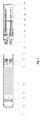
- a conventional electronic cigarette mainly includes a battery assembly and an atomization assembly, and a structure thereof is shown in Figure 1 .
- the battery assembly includes an end cover 11, a microphone controller 12, a microphone base 13, a battery 14, a battery sleeve 15, a bottom electrode 16, an electrode fixture 17 and a connection base 18.
- the atomization assembly includes a connector 20, a top electrode 21, a top insulating ring 22, an atomizer base 23, an atomizer 24, a cotton varnished sleeve 25, oil storage cotton 26, an atomizer sleeve 27 and a suction nozzle cover 28.
- the electronic cigarette can operate as long as the connection base 18 in the battery assembly is connected to the connector 20 in the atomization assembly.
- the atomization assembly can be used in combination with the battery assembly, as is found out by the inventor. Thereby, there may be a mismatch between powers of the battery assembly in the electronic cigarette and the atomization assembly.
- a high resistance of the atomization assembly can result in insufficient smoke generated in operation, and a low resistance of the atomization assembly can cause the battery to be over heated or fluid leakage, which result in poor user experience and may bring about a risk to security of a user.
- a battery assembly for an electronic cigarette, an electronic cigarette and a control method thereof are provided according to the present disclosure, to solve the problem that user experience is poor and there is a security risk in an electronic cigarette caused by a mismatch between powers of the battery assembly of the electronic cigarette and the atomization assembly in conventional technology.
- a battery assembly for an electronic cigarette, applied to form the electronic cigarette in combination with an atomization assembly, which includes:
- the electrical element is a resistor, and the resistor is connected in series between the second pin of the microcontroller and the low voltage end of the electric heating wire.
- the electrical element is an ammeter
- the ammeter is connected in series between the third pin of the microcontroller and the low voltage end of the electric heating wire, and the second pin is connected to the ammeter.
- the battery is rechargeable battery.
- the battery assembly further includes:
- the rechargeable battery includes a charging circuit and a power supply circuit.
- An electronic cigarette which includes any above-described battery assembly for an electronic cigarette.
- the electronic cigarette further includes:
- a control method of an electronic cigarette, applied to an electronic cigarette including any above-described battery assembly, is provided, which includes:
- determining the resistance of the electric heating wire of the atomization assembly includes:
- a battery assembly for an electric cigarette, an electric cigarette and a control method thereof are provided according to the present disclosure.
- the microcontroller is connected to both the battery and the atomization assembly, to form a current loop with the battery and the atomization assembly, and the microcontroller is connected to the high voltage end and the low voltage end of the electric heating wire of the atomization assembly via different pins.
- connection enable the microcontroller to determine the resistance of the electric heating wire by obtaining related parameters from the electric heating wire through the pins and control to open the circuit connected between the battery and the electric heating wire of the atomization assembly in a case that it is determined that the resistance of the electric heating wire of the atomization assembly is beyond the predetermined resistance range.
- the electronic cigarette can be controlled to stop operating in a case that there is a mismatch between powers of the battery assembly for the electronic cigarette and the atomization assembly, thereby avoiding occurrence of generating insufficient smoke and preventing the battery from being over heated and leaking fluid during use of the electronic cigarette.
- 11 end cover 12 microphone controller, 13 microphone base, 14 battery, 15 battery sleeve, 16 spring electrode, 17 electrode fixture, 18 connection base, 20 connector, 21 top electrode, 22 top insulating ring, 23 atomizer base, 24 electric heating wire, 25 PVC silicone fiberglass sleeving, 26 oil storage cotton, 27 atomizer sleeve, 28 seal ring, 29 suction nozzle cover.
- a battery assembly for an electronic cigarette and an electronic cigarette are provided according to the embodiments of the invention, where the electronic cigarette is provided with a function of determining a resistance of an electric heating wire in an atomization assembly, which ensures that the electronic cigarette can normally operate only in a case that a power of the battery assembly for the electronic cigarette matches that of the atomization assembly, thereby avoiding occurrence of generating insufficient smoke and preventing the battery from being over heated and leaking fluid during use of the electronic cigarette.
- FIG. 2 is a functional block diagram of a battery assembly for an electronic cigarette according to an embodiment of the invention.
- the battery assembly 10 for the electronic cigarette may be combined with an atomization assembly 20 to form the electronic cigarette, and includes a battery 101 and a microcontroller 102.
- the battery 101 may provide a voltage for an electric heating wire of the atomization assembly 20.
- the microcontroller 102 is connected to the battery 101 and the electric heating wire of the atomization assembly 20.
- the microcontroller 102 may control to open a circuit connected between the battery 101 and the electric heating wire of the atomization assembly 20 in a case that a resistance of the electric heating wire of the atomization assembly 20 is determined to be beyond a predetermined resistance range.
- the microcontroller 102 may include a first pin, a second pin and a third pin.
- the first pin is connected to a high voltage end of the electric heating wire
- the second pin is connected to a low voltage end of the electric heating wire via an electrical element 103
- the third pin is connected to the low voltage end of the electric heating wire.
- the microcontroller 102 is provided with a function of determining the resistance of the electric heating wire of the atomization assembly 20.
- a structure and an operating principle of the electronic cigarette according to the present disclosure are briefly described in conjunction with the above-described connections hereinafter.
- the battery assembly 10 for the electronic cigarette not only includes the battery 101, but also includes the microcontroller 102 connected to the battery and the electric heating wire of the atomization assembly 20.
- the microcontroller 102 can obtain electrical parameters from the electric heating wire, determine the resistance of the electric heating wire by performing some basic logical calculations on the obtained electrical parameters, and compare the resistance of the electric heating wire obtained through the calculations with the predetermined resistance range to determine whether the resistance is beyond the predetermined resistance range.
- the predetermined resistance range is determined based on a standard of matching a power of the battery assembly 10. The resistance being beyond the predetermined resistance range indicates that a power of the electric heating wire does not match that of the battery 101, that is, a power of the atomization assembly 20 does not match that of the battery assembly 10. If continuing to operate, the atomization assembly 20 may generate insufficient smoke or the battery may be over heated or leak fluid. Thus, in this case, the microcontroller 102 needs to open the circuit connected between the battery 101 and the electric heating wire of the atomization assembly 20.
- the electrical element 103 may be a resistor R1.
- the microcontroller 102 may include a first pin, a second pin and a third pin.
- the first pin is connected to a high voltage end of an electric heating wire L1
- the second pin connected to a low voltage end of the electric heating wire L1 via the resistor R1
- the third pin is connected to the low voltage end of the electric heating wire L1.
- the resistor R1 is connected in series between the second pin of the microcontroller 102 and the low voltage end of the electric heating wire L1, to detect and calculate a current through the electric heating wire L1.
- the microcontroller 102 can obtain a resistance of the electric heating wire L1 based on the calculated current.
- the resistance of the resistor R1 is known accordingly.
- the resistor R1 may be configured to have a low resistance, for example, 0.3 ⁇ .
- the microcontroller 102 can open the circuit connected between the battery 101 and the electric heating wire L1 of the atomization assembly 20 to stop the electronic cigarette from operating.
- the above-described method for detecting the resistance of the electric heating wire L1 of the atomization assembly 20 is not the only implementation, and reference can be made to Figure 4 for another implementation, where Figure 4 is a functional block diagram of another battery assembly for an electronic cigarette according to an embodiment of the invention.
- the electrical element 103 may be an ammeter A.
- the microcontroller 102 includes a first pin, a second pin and a third pin. The first pin is connected to the high voltage end of the electric heating wire L1,the third pin is connected to the low voltage end of the electric heating wire L1 via the ammeter A and the second pin is connected to the ammeter A.
- the current flowing through the electric heating wire L1 may further flow through the third pin of the microcontroller 102 and the battery 101 to form a current loop.
- the current I flowing through the electric heating wire L1 can be directly obtained with the ammeter A.
- the microcontroller 102 can obtain the current I through the second pin directly connected to the ammeter A and the resistance of the electric heating wire L1 can be calculated with the voltage across the electric heating wire L1 according to the Ohm's law.
- an operating process of the microcontroller 102 may include:
- a specific implementation of step S1 of determining the resistance of the electric heating wire of the atomization assembly may include determining the current through the electric heating wire and the voltage across the electric heating wire first and then calculating the resistance of the electric heating wire based on the current and the voltage of the electric heating wire according to the Ohm's law.
- the method may be implemented based on circuits with different connection structures, such as the connection structure as shown in Figure 3 or Figure 4 . Reference can be made to the descriptions above with respect to Figures 3 and 4 for specific connections of the connection structures as shown in Figures 3 and 4 , which are not redundantly described herein.
- the microcontroller in the battery assembly for an electronic cigarette is connected to both the battery and the atomization assembly, to form a current loop with the battery and the atomization assembly, and the microcontroller is connected to the high voltage end and the low voltage end of the electric heating wire of the atomization assembly via different pins.
- the connection enable the microcontroller to determine the resistance of the electric heating wire by obtaining related parameters from the electric heating wire through the pins and control to open the circuit connected between the battery and the electric heating wire of the atomization assembly in a case that it is determined that the resistance of the electric heating wire of the atomization assembly is beyond the predetermined resistance range.
- the electronic cigarette can be controlled to stop operating in a case that there is a mismatch between powers of the battery assembly for the electronic cigarette and the atomization assembly, thereby avoiding occurrence of generating insufficient smoke and preventing the battery from being over heated and leaking fluid during use of the electronic cigarette.
- FIG. 5 is a functional block diagram of a battery assembly for a fourth electronic cigarette according to an embodiment of the invention.
- the battery 101 according to the first embodiment may be a rechargeable battery, which includes a charging circuit and a power supply circuit. Since the charging circuit and the power supply circuit are the same as those according to conventional technology, for ease of illustration in Figure 5 , the charging circuit is represented by a charging module 501 and the power supply circuit is represented by a power supply module 502.
- the battery assembly 10 may further include an indicator lamp 503 connected to the microcontroller 102 and configured to indicate a charging status for a user to visually know an operating status of the battery assembly 10, such as a charging status and a power supply status.
- the indicator lamp 503 may indicate different operating statuses by displaying different colors.
- the battery assembly for an electronic cigarette has more detailed functions than the battery assembly for an electronic cigarette according to the first embodiment, such as a function of reusable charging and power supply and a function of indicating the operating status of the battery assembly, better perfecting functions of an electronic cigarette and facilitate using of a user.
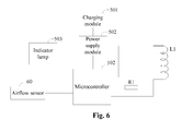
- FIG. 6 is a functional block diagram of the electronic cigarette according to the embodiment of the invention.
- the electronic cigarette in Figure 6 not only includes related structures according to the first and second embodiments, but also includes an airflow sensor 60 connected to the microcontroller 102.
- the airflow sensor 60 may include a micro air pressure switch, and an air pressure thereof changes when a user smokes.
- the micro air pressure switch can be turned on and send an instruction signal to the microcontroller 102.
- the microcontroller 102 can control the power supply circuit of the battery 101 to supply power to the electric heating wire L1 of the atomization assembly 20 in response to the instruction signal.
- the electronic cigarette may include the battery assembly for an electronic cigarette according to any of the implementations in the first and second embodiments, the electronic cigarette can also open the circuit connected between the battery and the electric heating wire of the atomization assembly in a case that the microcontroller determines the resistance of the electric heating wire of the atomization assembly is beyond the predetermined resistance range. In this way, the electronic cigarette can be controlled to stop operating in a case that a power of the battery assembly for an electronic cigarette does not match that of the atomization assembly, avoiding occurrence of generating insufficient smoke and preventing the battery from being over heated and leaking fluid during use of the electronic cigarette.
Landscapes
- Engineering & Computer Science (AREA)
- Chemical & Material Sciences (AREA)
- Chemical Kinetics & Catalysis (AREA)
- General Chemical & Material Sciences (AREA)
- Manufacturing & Machinery (AREA)
- Electrochemistry (AREA)
- Power Engineering (AREA)
- Microelectronics & Electronic Packaging (AREA)
- Charge And Discharge Circuits For Batteries Or The Like (AREA)
- Health & Medical Sciences (AREA)
- Control Of Resistance Heating (AREA)
- Secondary Cells (AREA)
- Bioinformatics & Cheminformatics (AREA)
- Pulmonology (AREA)
- Anesthesiology (AREA)
- Biomedical Technology (AREA)
- Heart & Thoracic Surgery (AREA)
- Hematology (AREA)
- Life Sciences & Earth Sciences (AREA)
- Animal Behavior & Ethology (AREA)
- General Health & Medical Sciences (AREA)
- Public Health (AREA)
- Veterinary Medicine (AREA)
Abstract
Description
- This application claims priority to
Chinese Patent Application No. 201420051821.3 - The present disclosure relates to the technical field of electronic cigarettes, and in particular to a battery assembly for an electronic cigarette, an electronic cigarette and a control method thereof.
- A conventional electronic cigarette mainly includes a battery assembly and an atomization assembly, and a structure thereof is shown in
Figure 1 . The battery assembly includes anend cover 11, amicrophone controller 12, amicrophone base 13, abattery 14, abattery sleeve 15, abottom electrode 16, anelectrode fixture 17 and aconnection base 18. The atomization assembly includes aconnector 20, atop electrode 21, atop insulating ring 22, anatomizer base 23, anatomizer 24, a cotton varnishedsleeve 25,oil storage cotton 26, anatomizer sleeve 27 and asuction nozzle cover 28. - With reference to
Figure 1 , the electronic cigarette can operate as long as theconnection base 18 in the battery assembly is connected to theconnector 20 in the atomization assembly. There are varieties of atomization assemblies available in market now, resistances of electric heating wires in different kinds of atomization assemblies are different, and for an atomization assembly with any parameter or conforming to any standard, as long as an interface structure thereof matches that of a battery assembly in an electronic cigarette, the atomization assembly can be used in combination with the battery assembly, as is found out by the inventor. Thereby, there may be a mismatch between powers of the battery assembly in the electronic cigarette and the atomization assembly. A high resistance of the atomization assembly can result in insufficient smoke generated in operation, and a low resistance of the atomization assembly can cause the battery to be over heated or fluid leakage, which result in poor user experience and may bring about a risk to security of a user. - In view of the above, a battery assembly for an electronic cigarette, an electronic cigarette and a control method thereof are provided according to the present disclosure, to solve the problem that user experience is poor and there is a security risk in an electronic cigarette caused by a mismatch between powers of the battery assembly of the electronic cigarette and the atomization assembly in conventional technology.
- To achieve the object above, following technical solutions are provided according to the present disclosure.
- A battery assembly for an electronic cigarette, applied to form the electronic cigarette in combination with an atomization assembly, is provided, which includes:
- a battery, configured to provide a voltage for an electric heating wire of the atomization assembly; and
- a microcontroller, connected to the battery and the electric heating wire of the atomization assembly and configured to control to open a circuit connected between the battery and the electric heating wire of the atomization assembly in a case that a resistance of the electric heating wire of the atomization assembly is determined to be beyond a predetermined resistance range,
- Optionally, the electrical element is a resistor, and the resistor is connected in series between the second pin of the microcontroller and the low voltage end of the electric heating wire.
- Optionally, the electrical element is an ammeter, the ammeter is connected in series between the third pin of the microcontroller and the low voltage end of the electric heating wire, and the second pin is connected to the ammeter.
- Optionally, the battery is rechargeable battery.
- Optionally, the battery assembly further includes:
- an indicator lamp, connected to the microcontroller and configured to indicate a charging status.
- Optionally, the rechargeable battery includes a charging circuit and a power supply circuit.
- An electronic cigarette is provided, which includes any above-described battery assembly for an electronic cigarette.
- Optionally, the electronic cigarette further includes:
- an airflow sensor connected to the microcontroller.
- A control method of an electronic cigarette, applied to an electronic cigarette including any above-described battery assembly, is provided, which includes:
- determining a resistance of the electric heating wire of the atomization assembly;
- determining whether the resistance is beyond a predetermined resistance range; and
- opening the circuit connected between the battery and the electric heating wire of the atomization assembly in a case that the resistance is beyond the predetermined resistance range.
- Optionally, determining the resistance of the electric heating wire of the atomization assembly includes:
- obtaining a current through the electric heating wire and a voltage across the electric heating wire; and
- determining the resistance of the electric heating wire of the atomization assembly by performing calculation based on the current and the voltage.
- According to the technical solutions above, compared with conventional technology, a battery assembly for an electric cigarette, an electric cigarette and a control method thereof are provided according to the present disclosure. In the battery assembly for the electric cigarette, the microcontroller is connected to both the battery and the atomization assembly, to form a current loop with the battery and the atomization assembly, and the microcontroller is connected to the high voltage end and the low voltage end of the electric heating wire of the atomization assembly via different pins. The connection enable the microcontroller to determine the resistance of the electric heating wire by obtaining related parameters from the electric heating wire through the pins and control to open the circuit connected between the battery and the electric heating wire of the atomization assembly in a case that it is determined that the resistance of the electric heating wire of the atomization assembly is beyond the predetermined resistance range. In this way, the electronic cigarette can be controlled to stop operating in a case that there is a mismatch between powers of the battery assembly for the electronic cigarette and the atomization assembly, thereby avoiding occurrence of generating insufficient smoke and preventing the battery from being over heated and leaking fluid during use of the electronic cigarette.
- The drawings to be used in the descriptions of embodiments or conventional technology are described briefly as follows, so that technical solutions according to the embodiments of the invention or according to conventional technology may become clearer. Apparently, the drawings in the following descriptions only illustrate some embodiments of the invention. For those in the art, other drawings may be obtained based on these drawings without any creative work.
-
Figure 1 is a schematic structural diagram of an electronic cigarette according to conventional technology; -
Figure 2 is a functional block diagram of a battery assembly for an electronic cigarette according to an embodiment of the invention; -
Figure 3 is a functional block diagram of a battery assembly for an electronic cigarette according to an embodiment of the invention; -
Figure 4 is a functional block diagram of a battery assembly for an electronic cigarette according to an embodiment of the invention; -
Figure 5 is a functional block diagram of a battery assembly for an electronic cigarette according to an embodiment of the invention; and -
Figure 6 is a functional block diagram of an electronic cigarette according to an embodiment of the invention. - 11 end cover, 12 microphone controller, 13 microphone base, 14 battery, 15 battery sleeve, 16 spring electrode, 17 electrode fixture, 18 connection base, 20 connector, 21 top electrode, 22 top insulating ring, 23 atomizer base, 24 electric heating wire, 25 PVC silicone fiberglass sleeving, 26 oil storage cotton, 27 atomizer sleeve, 28 seal ring, 29 suction nozzle cover.
- A battery assembly for an electronic cigarette and an electronic cigarette are provided according to the embodiments of the invention, where the electronic cigarette is provided with a function of determining a resistance of an electric heating wire in an atomization assembly, which ensures that the electronic cigarette can normally operate only in a case that a power of the battery assembly for the electronic cigarette matches that of the atomization assembly, thereby avoiding occurrence of generating insufficient smoke and preventing the battery from being over heated and leaking fluid during use of the electronic cigarette.
- Technical solutions according to the embodiments of the invention are described clearly and completely hereinafter in conjunction with the drawings. Apparently, the described embodiments are only a few rather than all of the embodiments of the invention. Any other embodiments obtained by those skilled in the art based on the embodiments according to the present disclosure without any creative work fall in the scope of the present disclosure.
-
Figure 2 is a functional block diagram of a battery assembly for an electronic cigarette according to an embodiment of the invention. As shown inFigure 2 , thebattery assembly 10 for the electronic cigarette may be combined with anatomization assembly 20 to form the electronic cigarette, and includes abattery 101 and amicrocontroller 102. - The
battery 101 may provide a voltage for an electric heating wire of theatomization assembly 20. Themicrocontroller 102 is connected to thebattery 101 and the electric heating wire of theatomization assembly 20. Themicrocontroller 102 may control to open a circuit connected between thebattery 101 and the electric heating wire of theatomization assembly 20 in a case that a resistance of the electric heating wire of theatomization assembly 20 is determined to be beyond a predetermined resistance range. - The
microcontroller 102 may include a first pin, a second pin and a third pin. The first pin is connected to a high voltage end of the electric heating wire, the second pin is connected to a low voltage end of the electric heating wire via anelectrical element 103 and the third pin is connected to the low voltage end of the electric heating wire. - In this way, the
microcontroller 102 is provided with a function of determining the resistance of the electric heating wire of theatomization assembly 20. A structure and an operating principle of the electronic cigarette according to the present disclosure are briefly described in conjunction with the above-described connections hereinafter. - The
battery assembly 10 for the electronic cigarette not only includes thebattery 101, but also includes themicrocontroller 102 connected to the battery and the electric heating wire of theatomization assembly 20. Themicrocontroller 102 can obtain electrical parameters from the electric heating wire, determine the resistance of the electric heating wire by performing some basic logical calculations on the obtained electrical parameters, and compare the resistance of the electric heating wire obtained through the calculations with the predetermined resistance range to determine whether the resistance is beyond the predetermined resistance range. The predetermined resistance range is determined based on a standard of matching a power of thebattery assembly 10. The resistance being beyond the predetermined resistance range indicates that a power of the electric heating wire does not match that of thebattery 101, that is, a power of theatomization assembly 20 does not match that of thebattery assembly 10. If continuing to operate, theatomization assembly 20 may generate insufficient smoke or the battery may be over heated or leak fluid. Thus, in this case, themicrocontroller 102 needs to open the circuit connected between thebattery 101 and the electric heating wire of theatomization assembly 20. - Reference can be made to
Figure 3 for a possible implementation, whereFigure 3 is a functional block diagram of another battery assembly for an electronic cigarette according to an embodiment of the invention. As shown inFigure 3 , theelectrical element 103 may be a resistor R1. Themicrocontroller 102 may include a first pin, a second pin and a third pin. The first pin is connected to a high voltage end of an electric heating wire L1, the second pin connected to a low voltage end of the electric heating wire L1 via the resistor R1 and the third pin is connected to the low voltage end of the electric heating wire L1. The resistor R1 is connected in series between the second pin of themicrocontroller 102 and the low voltage end of the electric heating wire L1, to detect and calculate a current through the electric heating wire L1. Thus, themicrocontroller 102 can obtain a resistance of the electric heating wire L1 based on the calculated current. The resistance of the resistor R1 is known accordingly. To maximally reduce influence on normal operating of the electronic cigarette, the resistor R1 may be configured to have a low resistance, for example, 0.3Ω. - The operating principle of the electronic cigarette according to the embodiment is described hereinafter in conjunction with
Figure 3 . At the beginning of operating of the electronic cigarette, a power supply switch of the electric heating wire L1 is turned on under the control of themicrocontroller 102. A current will flow through the electric heating wire L1 and the electric heating wire L1 becomes heated. Meanwhile, the first and third pins of themicrocontroller 102 detect a voltage across the electric heating wire L1. The current flowing through the electric heating wire L1 further flows through the resistor R1 to form a loop. A voltage drop across the resistor R1 is generated and is inputted into themicrocontroller 102 through the second and third pins. Themicrocontroller 102 obtains the current through the resistor R1 according to the Ohm's law, that is, the current I through the electric heating wire, where I= voltage across R1/ resistance of R1, and calculates the resistance R of the electric heating wire L1 based on the obtained current I, where R= voltage across the electric heating wire/current I through the electric heating wire. Further, after the resistance R of the electric heating wire L1 is determined, the resistance R is compared with the predetermined resistance range, that is, determining whether the resistance R is lower than a predetermined minimum resistance or higher than a predetermined maximum resistance. In a case that the resistance of the electric heating wire L1 of theatomization assembly 20 is determined to be beyond the predetermined resistance range, themicrocontroller 102 can open the circuit connected between thebattery 101 and the electric heating wire L1 of theatomization assembly 20 to stop the electronic cigarette from operating. - Of course, the above-described method for detecting the resistance of the electric heating wire L1 of the
atomization assembly 20 is not the only implementation, and reference can be made toFigure 4 for another implementation, whereFigure 4 is a functional block diagram of another battery assembly for an electronic cigarette according to an embodiment of the invention. As shown inFigure 4 , theelectrical element 103 may be an ammeter A. Themicrocontroller 102 includes a first pin, a second pin and a third pin. The first pin is connected to the high voltage end of the electric heating wire L1,the third pin is connected to the low voltage end of the electric heating wire L1 via the ammeter A and the second pin is connected to the ammeter A. The current flowing through the electric heating wire L1 may further flow through the third pin of themicrocontroller 102 and thebattery 101 to form a current loop. The current I flowing through the electric heating wire L1 can be directly obtained with the ammeter A. Themicrocontroller 102 can obtain the current I through the second pin directly connected to the ammeter A and the resistance of the electric heating wire L1 can be calculated with the voltage across the electric heating wire L1 according to the Ohm's law. - To be specific, an operating process of the
microcontroller 102 may include: - step S1, determining the resistance of the electric heating wire of the atomization assembly;
- step S2, determining whether the resistance is beyond the predetermined resistance range; and
- step S3, control to open the circuit connected between the battery and the electric heating wire of the atomization assembly in a case that the resistance is beyond the predetermined resistance range.
- A specific implementation of step S1 of determining the resistance of the electric heating wire of the atomization assembly may include determining the current through the electric heating wire and the voltage across the electric heating wire first and then calculating the resistance of the electric heating wire based on the current and the voltage of the electric heating wire according to the Ohm's law. The method may be implemented based on circuits with different connection structures, such as the connection structure as shown in
Figure 3 orFigure 4 . Reference can be made to the descriptions above with respect toFigures 3 and4 for specific connections of the connection structures as shown inFigures 3 and4 , which are not redundantly described herein. - In the embodiment, the microcontroller in the battery assembly for an electronic cigarette is connected to both the battery and the atomization assembly, to form a current loop with the battery and the atomization assembly, and the microcontroller is connected to the high voltage end and the low voltage end of the electric heating wire of the atomization assembly via different pins. The connection enable the microcontroller to determine the resistance of the electric heating wire by obtaining related parameters from the electric heating wire through the pins and control to open the circuit connected between the battery and the electric heating wire of the atomization assembly in a case that it is determined that the resistance of the electric heating wire of the atomization assembly is beyond the predetermined resistance range. In this way, the electronic cigarette can be controlled to stop operating in a case that there is a mismatch between powers of the battery assembly for the electronic cigarette and the atomization assembly, thereby avoiding occurrence of generating insufficient smoke and preventing the battery from being over heated and leaking fluid during use of the electronic cigarette.
-
Figure 5 is a functional block diagram of a battery assembly for a fourth electronic cigarette according to an embodiment of the invention. In the embodiment, detailed structural division and addition of structures are made to the implementations according to the first embodiment. As shown inFigure 5 , thebattery 101 according to the first embodiment may be a rechargeable battery, which includes a charging circuit and a power supply circuit. Since the charging circuit and the power supply circuit are the same as those according to conventional technology, for ease of illustration inFigure 5 , the charging circuit is represented by acharging module 501 and the power supply circuit is represented by apower supply module 502. Thebattery assembly 10 may further include anindicator lamp 503 connected to themicrocontroller 102 and configured to indicate a charging status for a user to visually know an operating status of thebattery assembly 10, such as a charging status and a power supply status. Theindicator lamp 503 may indicate different operating statuses by displaying different colors. - In the embodiment, the battery assembly for an electronic cigarette has more detailed functions than the battery assembly for an electronic cigarette according to the first embodiment, such as a function of reusable charging and power supply and a function of indicating the operating status of the battery assembly, better perfecting functions of an electronic cigarette and facilitate using of a user.
- An electronic cigarette is further provided according to an embodiment of the invention, which may include the
battery assembly 10 for an electronic cigarette according to any of the implementations in the embodiments above.Figure 6 is a functional block diagram of the electronic cigarette according to the embodiment of the invention. The electronic cigarette inFigure 6 not only includes related structures according to the first and second embodiments, but also includes anairflow sensor 60 connected to themicrocontroller 102. Theairflow sensor 60 may include a micro air pressure switch, and an air pressure thereof changes when a user smokes. In this case, the micro air pressure switch can be turned on and send an instruction signal to themicrocontroller 102. Themicrocontroller 102 can control the power supply circuit of thebattery 101 to supply power to the electric heating wire L1 of theatomization assembly 20 in response to the instruction signal. - Since the electronic cigarette according to the embodiment may include the battery assembly for an electronic cigarette according to any of the implementations in the first and second embodiments, the electronic cigarette can also open the circuit connected between the battery and the electric heating wire of the atomization assembly in a case that the microcontroller determines the resistance of the electric heating wire of the atomization assembly is beyond the predetermined resistance range. In this way, the electronic cigarette can be controlled to stop operating in a case that a power of the battery assembly for an electronic cigarette does not match that of the atomization assembly, avoiding occurrence of generating insufficient smoke and preventing the battery from being over heated and leaking fluid during use of the electronic cigarette.
- The embodiments in the specification are described in a progressive manner, each of which emphasizes differences from the others, and reference can be made to each other for same or similar parts.
- The description of the embodiments herein enables those skilled in the art to implement or use the present disclosure. Numerous modifications to the embodiments are apparent to those skilled in the art, and the general principles defined herein can be implemented in other embodiments without deviating from the spirit or scope of the present disclosure. Therefore, the invention is not limited to the embodiments described herein, but is in accordance with the widest scope consistent with the principles and novel features disclosed herein.
Claims (10)
- A battery assembly for an electronic cigarette, applied to form the electronic cigarette in combination with an atomization assembly, comprising:a battery, configured to provide a voltage for an electric heating wire of the atomization assembly; anda microcontroller, connected to the battery and the electric heating wire of the atomization assembly and configured to control to open a circuit connected between the battery and the electric heating wire of the atomization assembly in a case that a resistance of the electric heating wire of the atomization assembly is determined to be beyond a predetermined resistance range,wherein the microcontroller comprises a first pin, a second pin and a third pin, the first pin is connected to a high voltage end of the electric heating wire, the second pin is connected to a low voltage end of the electric heating wire via an electrical element and the third pin is connected to the low voltage end of the electric heating wire.
- The battery assembly for an electronic cigarette according to claim 1, wherein the electrical element is a resistor connected in series between the second pin of the microcontroller and the low voltage end of the electric heating wire.
- The battery assembly for an electronic cigarette according to claim 1, wherein the electrical element is an ammeter connected in series between the third pin of the microcontroller and the low voltage end of the electric heating wire, and the second pin is connected to the ammeter.
- The battery assembly for an electronic cigarette according to claim 1, wherein the battery is a rechargeable battery.
- The battery assembly for an electronic cigarette according to claim 4, further comprising:an indicator lamp, connected to the microcontroller and configured to indicate a charging status.
- The battery assembly for an electronic cigarette according to claim 4, wherein the rechargeable battery comprises a charging circuit and a power supply circuit.
- An electronic cigarette, comprising the battery assembly for an electronic cigarette according to any one of claims 1 to 6.
- The electronic cigarette according to claim 7, further comprising:an airflow sensor connected to the microcontroller.
- A control method of an electronic cigarette, applied to an electronic cigarette comprising the battery assembly according to any one of claims 1 to 6, comprising:determining a resistance of the electric heating wire of the atomization assembly;determining whether the resistance is beyond a predetermined resistance range; andopening the circuit connected between the battery and the electric heating wire of the atomization assembly in a case that the resistance is beyond the predetermined resistance range.
- The control method of an electronic cigarette according to claim 9, wherein determining the resistance of the electric heating wire of the atomization assembly comprises:obtaining a current through the electric heating wire and a voltage across the electric heating wire; anddetermining the resistance of the electric heating wire of the atomization assembly by performing calculation based on the current and the voltage.
Applications Claiming Priority (2)
| Application Number | Priority Date | Filing Date | Title |
|---|---|---|---|
| CN201420051821.3U CN203618789U (en) | 2014-01-26 | 2014-01-26 | Battery pack of electronic cigarette, and electronic cigarette |
| PCT/CN2014/072312 WO2015109626A1 (en) | 2014-01-26 | 2014-02-20 | Battery assembly for electronic cigarette, electronic cigarette and control method therefor |
Publications (2)
| Publication Number | Publication Date |
|---|---|
| EP3097799A1 true EP3097799A1 (en) | 2016-11-30 |
| EP3097799A4 EP3097799A4 (en) | 2017-10-11 |
Family
ID=50805334
Family Applications (1)
| Application Number | Title | Priority Date | Filing Date |
|---|---|---|---|
| EP14879357.3A Withdrawn EP3097799A4 (en) | 2014-01-26 | 2014-02-20 | Battery assembly for electronic cigarette, electronic cigarette and control method therefor |
Country Status (7)
| Country | Link |
|---|---|
| US (1) | US20160316822A1 (en) |
| EP (1) | EP3097799A4 (en) |
| JP (1) | JP2017503520A (en) |
| KR (1) | KR20160107308A (en) |
| CN (2) | CN203618789U (en) |
| CA (1) | CA2936702A1 (en) |
| WO (1) | WO2015109626A1 (en) |
Families Citing this family (54)
| Publication number | Priority date | Publication date | Assignee | Title |
|---|---|---|---|---|
| US10244793B2 (en) | 2005-07-19 | 2019-04-02 | Juul Labs, Inc. | Devices for vaporization of a substance |
| US10279934B2 (en) | 2013-03-15 | 2019-05-07 | Juul Labs, Inc. | Fillable vaporizer cartridge and method of filling |
| US10039321B2 (en) | 2013-11-12 | 2018-08-07 | Vmr Products Llc | Vaporizer |
| KR102267997B1 (en) | 2013-12-23 | 2021-06-23 | 쥴 랩스, 인크. | Vaporization device systems and methods |
| USD825102S1 (en) | 2016-07-28 | 2018-08-07 | Juul Labs, Inc. | Vaporizer device with cartridge |
| US20160366947A1 (en) | 2013-12-23 | 2016-12-22 | James Monsees | Vaporizer apparatus |
| US10159282B2 (en) | 2013-12-23 | 2018-12-25 | Juul Labs, Inc. | Cartridge for use with a vaporizer device |
| US10076139B2 (en) | 2013-12-23 | 2018-09-18 | Juul Labs, Inc. | Vaporizer apparatus |
| USD842536S1 (en) | 2016-07-28 | 2019-03-05 | Juul Labs, Inc. | Vaporizer cartridge |
| US10058129B2 (en) | 2013-12-23 | 2018-08-28 | Juul Labs, Inc. | Vaporization device systems and methods |
| CN203618789U (en) * | 2014-01-26 | 2014-06-04 | 惠州市吉瑞科技有限公司 | Battery pack of electronic cigarette, and electronic cigarette |
| CN104049550B (en) * | 2014-06-19 | 2017-09-26 | 卓尔悦欧洲控股有限公司 | Control method and device of multi-output mode electronic cigarette |
| GB2528712B (en) | 2014-07-29 | 2019-03-27 | Nicoventures Holdings Ltd | E-cigarette and re-charging pack |
| CN206303206U (en) * | 2014-09-04 | 2017-07-07 | 惠州市吉瑞科技有限公司 | Atomizer resistance test device |
| CN104323428B (en) * | 2014-10-24 | 2017-10-17 | 林光榕 | Temperature control electronic cigarette and its temprature control method |
| CN105686085B (en) * | 2014-11-24 | 2019-06-28 | 惠州市吉瑞科技有限公司 | Atomizer assembly, the electronic cigarette for limiting the service life and the method for limiting the electronic cigarette service life |
| KR102627987B1 (en) | 2014-12-05 | 2024-01-22 | 쥴 랩스, 인크. | Calibrated dose control |
| EP4183282B1 (en) | 2014-12-25 | 2025-12-17 | Fontem Ventures B.V. | Dynamic output power management for electronic smoking device |
| EP3824749A1 (en) * | 2015-03-26 | 2021-05-26 | Philip Morris Products S.A. | Heater management |
| US10874139B2 (en) * | 2015-07-07 | 2020-12-29 | Altria Client Services Llc | E-vapor device including capsule containing pre-vapor formulation |
| CN106333387B (en) * | 2015-07-15 | 2023-10-03 | 深圳市新宜康科技股份有限公司 | Multi-resistance implementation method and layout structure of electronic cigarette heating wire |
| US10524505B2 (en) | 2015-08-06 | 2020-01-07 | Altria Client Services Llc. | Method for measuring a vapor precursor level in a cartomizer of an electronic vaping device and/or an electronic vaping device configured to perform the method |
| CN105394818B (en) * | 2015-12-09 | 2020-01-24 | 卓尔悦欧洲控股有限公司 | Electronic cigarette battery, electronic cigarette and control method thereof |
| MX377347B (en) | 2016-02-11 | 2025-03-07 | Juul Labs Inc | Fillable vaporizer cartridge and method of filling |
| WO2017139675A1 (en) | 2016-02-11 | 2017-08-17 | Pax Labs, Inc. | Securely attaching cartridges for vaporizer devices |
| US10405582B2 (en) | 2016-03-10 | 2019-09-10 | Pax Labs, Inc. | Vaporization device with lip sensing |
| USD849996S1 (en) | 2016-06-16 | 2019-05-28 | Pax Labs, Inc. | Vaporizer cartridge |
| USD851830S1 (en) | 2016-06-23 | 2019-06-18 | Pax Labs, Inc. | Combined vaporizer tamp and pick tool |
| USD848057S1 (en) | 2016-06-23 | 2019-05-07 | Pax Labs, Inc. | Lid for a vaporizer |
| USD836541S1 (en) | 2016-06-23 | 2018-12-25 | Pax Labs, Inc. | Charging device |
| CN106292772A (en) * | 2016-08-18 | 2017-01-04 | 陈镇江 | A electronic cigarette temperature control system based on joule mode |
| CA3046954C (en) | 2016-12-12 | 2024-01-02 | Vmr Products Llc | Refillable cartridge for vaporizer |
| CN107404107B (en) * | 2017-08-15 | 2020-02-14 | 惠州市新泓威科技有限公司 | Dry burning prevention device of electronic cigarette and control method thereof |
| USD887632S1 (en) | 2017-09-14 | 2020-06-16 | Pax Labs, Inc. | Vaporizer cartridge |
| JP6792905B2 (en) | 2018-01-26 | 2020-12-02 | 日本たばこ産業株式会社 | Manufacturing method of aerosol generator and aerosol generator |
| CN111655053B (en) | 2018-01-26 | 2024-06-11 | 日本烟草产业株式会社 | Aerosol generating device, method for operating the device, and storage medium |
| KR102500892B1 (en) | 2018-01-26 | 2023-02-17 | 니뽄 다바코 산교 가부시키가이샤 | Aerosol generating device and method and program for operating same |
| WO2019148038A1 (en) | 2018-01-26 | 2019-08-01 | Juul Labs, Inc. | Charging case assembly |
| KR102373331B1 (en) * | 2018-05-11 | 2022-03-11 | 주식회사 이엠텍 | Method for preventing over-heating and malfunction of fine particle generator |
| US12543799B2 (en) | 2018-11-02 | 2026-02-10 | Juul Labs, Inc. | Vaporizer device with charging and reverse-charging capability |
| EP4537877A3 (en) | 2018-11-05 | 2025-06-04 | Juul Labs, Inc. | Cartridges for vaporizer devices |
| CN109587833B (en) * | 2018-12-04 | 2024-03-08 | 潍坊正达实业有限公司 | Electronic cigarette circuit and electronic cigarette |
| EP3906074A1 (en) | 2018-12-31 | 2021-11-10 | Juul Labs, Inc. | Cartridges for vaporizer devices |
| CN109480342B (en) * | 2019-01-04 | 2024-05-28 | 惠州市新泓威科技有限公司 | Electronic cigarette encrypted by wireless electronic tag and encryption method thereof |
| JP6647435B1 (en) | 2019-01-17 | 2020-02-14 | 日本たばこ産業株式会社 | Power supply unit for aerosol inhaler |
| CN110074465A (en) * | 2019-05-20 | 2019-08-02 | 深圳市合元科技有限公司 | Electronic cigarette and its control method and atomizer |
| JP6678936B1 (en) | 2019-05-31 | 2020-04-15 | 日本たばこ産業株式会社 | Control device for aerosol aspirator and aerosol aspirator |
| JP6613008B1 (en) | 2019-05-31 | 2019-11-27 | 日本たばこ産業株式会社 | Control device for aerosol inhaler and aerosol inhaler |
| KR102501323B1 (en) * | 2020-05-30 | 2023-02-17 | 항저우 선갓 세미컨덕터 컴퍼니 리미티드 | Electronic atomizer and its control assembly and battery module |
| CN213344350U (en) * | 2020-09-07 | 2021-06-04 | 深圳市美深威科技有限公司 | Atomizer and electronic cigarette |
| CN112931962B (en) * | 2021-03-15 | 2023-10-20 | 深圳麦克韦尔科技有限公司 | Method for identifying atomizer and battery pole applied by same |
| CN115656767A (en) * | 2022-08-31 | 2023-01-31 | 广东弗我智能制造有限公司 | Universal atomizer detection method |
| USD1063191S1 (en) | 2023-02-03 | 2025-02-18 | Juul Labs, Inc. | Case |
| WO2024263021A1 (en) * | 2023-06-23 | 2024-12-26 | 주식회사 삼진엘앤디 | Aerosol generation device capable of adjusting light absorption wavelength |
Family Cites Families (17)
| Publication number | Priority date | Publication date | Assignee | Title |
|---|---|---|---|---|
| EP2100525A1 (en) * | 2008-03-14 | 2009-09-16 | Philip Morris Products S.A. | Electrically heated aerosol generating system and method |
| EP2468116A1 (en) * | 2010-12-24 | 2012-06-27 | Philip Morris Products S.A. | An aerosol generating system having means for handling consumption of a liquid substrate |
| CN102884710B (en) * | 2011-01-28 | 2015-11-25 | 惠州市吉瑞科技有限公司 | A kind of wireless charging device |
| JP5272200B2 (en) * | 2011-08-25 | 2013-08-28 | 和彦 清水 | Smokeless smoking jig |
| HUE040751T2 (en) * | 2011-10-27 | 2019-03-28 | Philip Morris Products Sa | Aerosol generating system with improved aerosol production |
| EP2609820A1 (en) * | 2011-12-30 | 2013-07-03 | Philip Morris Products S.A. | Detection of aerosol-forming substrate in an aerosol generating device |
| CN104114049A (en) * | 2012-03-26 | 2014-10-22 | 韩国极光科技有限公司 | Atomization control unit and a portable atomizing apparatus having the same |
| WO2013181789A1 (en) * | 2012-06-04 | 2013-12-12 | Liu Qiuming | Electronic cigarette circuit |
| US10004259B2 (en) * | 2012-06-28 | 2018-06-26 | Rai Strategic Holdings, Inc. | Reservoir and heater system for controllable delivery of multiple aerosolizable materials in an electronic smoking article |
| CN202749479U (en) * | 2012-08-23 | 2013-02-20 | 卓尔悦(常州)电子科技有限公司 | Voltage-adjustable battery for electronic cigarettes |
| CN102940313B (en) * | 2012-11-13 | 2015-04-01 | 卓尔悦(常州)电子科技有限公司 | Intelligent controller and intelligent control method for electronic cigarette |
| CN202890465U (en) * | 2012-11-13 | 2013-04-24 | 卓尔悦(常州)电子科技有限公司 | Intelligent controller for electronic cigarette |
| CN202980150U (en) * | 2012-12-27 | 2013-06-12 | 深圳市康泓威科技有限公司 | Electronic cigarette |
| CN203152492U (en) * | 2013-04-01 | 2013-08-28 | 向智勇 | Electronic cigarette case with disinfection function |
| CN203341005U (en) * | 2013-05-15 | 2013-12-18 | 杭州联声电子有限公司 | Chargeable electronic cigarette controller |
| CN203618789U (en) * | 2014-01-26 | 2014-06-04 | 惠州市吉瑞科技有限公司 | Battery pack of electronic cigarette, and electronic cigarette |
| US20150224268A1 (en) * | 2014-02-07 | 2015-08-13 | R.J. Reynolds Tobacco Company | Charging Accessory Device for an Aerosol Delivery Device and Related System, Method, Apparatus, and Computer Program Product for Providing Interactive Services for Aerosol Delivery Devices |
-
2014
- 2014-01-26 CN CN201420051821.3U patent/CN203618789U/en not_active Expired - Fee Related
- 2014-02-20 WO PCT/CN2014/072312 patent/WO2015109626A1/en not_active Ceased
- 2014-02-20 CN CN201480072720.7A patent/CN105899094B/en not_active Expired - Fee Related
- 2014-02-20 CA CA2936702A patent/CA2936702A1/en not_active Abandoned
- 2014-02-20 JP JP2016548021A patent/JP2017503520A/en active Pending
- 2014-02-20 EP EP14879357.3A patent/EP3097799A4/en not_active Withdrawn
- 2014-02-20 KR KR1020167022052A patent/KR20160107308A/en not_active Ceased
-
2016
- 2016-07-13 US US15/209,751 patent/US20160316822A1/en not_active Abandoned
Also Published As
| Publication number | Publication date |
|---|---|
| CN105899094B (en) | 2019-05-14 |
| WO2015109626A1 (en) | 2015-07-30 |
| JP2017503520A (en) | 2017-02-02 |
| KR20160107308A (en) | 2016-09-13 |
| CN203618789U (en) | 2014-06-04 |
| CN105899094A (en) | 2016-08-24 |
| US20160316822A1 (en) | 2016-11-03 |
| EP3097799A4 (en) | 2017-10-11 |
| CA2936702A1 (en) | 2015-07-30 |
Similar Documents
| Publication | Publication Date | Title |
|---|---|---|
| EP3097799A1 (en) | Battery assembly for electronic cigarette, electronic cigarette and control method therefor | |
| EA201891850A1 (en) | AROMATIC INHALER NON-BURNING TYPE, METHOD, PROGRAM AND RECORDING MEDIA | |
| EP3127442A1 (en) | Electronic cigarette and atomization control method thereof | |
| CN107244252B (en) | A circuit for indicating the state of AC and DC charging guns | |
| WO2017156743A1 (en) | Electronic cigarette control circuit, control method and electronic cigarette | |
| WO2016119145A1 (en) | Electronic cigarette and method for displaying tobacco oil surplus | |
| CN104880602A (en) | Air conditioner, and detection method and apparatus for electric heater of air conditioner | |
| CN104965536B (en) | temperature control circuit and temperature control method | |
| TW201914195A (en) | Adapter and adapter module having the same | |
| CN104101808A (en) | Charger detecting system and detecting method thereof and mobile terminal | |
| CN111007321B (en) | Processing circuit at power output end, electronic device and ground impedance detection method | |
| CN204333898U (en) | An inverter air conditioner and its intelligent power module overcurrent protection adjustment circuit | |
| CN105198044B (en) | A kind of solution is electrolysed atomising device | |
| JP2014178313A (en) | Testing device and method | |
| CN205539299U (en) | Detection apparatus for testable connection exactness | |
| CN103439997B (en) | The electric soldering iron control method of adjustable thermostatic and device | |
| CN102148487B (en) | Fusing device for printed circuit board (PCB) short-circuit power supply and control method thereof | |
| CN208258999U (en) | A kind of control circuit of automatic identification atomizer | |
| CN106130141A (en) | A kind of charge control method, charging system and electronic equipment | |
| KR20150022187A (en) | Electric soldering iron having temperature setting device | |
| CN114992872B (en) | A gas water heater and its control method | |
| CN104518253A (en) | Prompt method of battery capacity, device, battery and electronic equipment | |
| CN204241230U (en) | A kind of lambda sensor electronic simulator | |
| CN203813173U (en) | Adapter socket with fire hazard and smoke alarm and power-off functions | |
| CN106684960B (en) | A kind of charge control method, charging system and electronic equipment |
Legal Events
| Date | Code | Title | Description |
|---|---|---|---|
| PUAI | Public reference made under article 153(3) epc to a published international application that has entered the european phase |
Free format text: ORIGINAL CODE: 0009012 |
|
| 17P | Request for examination filed |
Effective date: 20160803 |
|
| AK | Designated contracting states |
Kind code of ref document: A1 Designated state(s): AL AT BE BG CH CY CZ DE DK EE ES FI FR GB GR HR HU IE IS IT LI LT LU LV MC MK MT NL NO PL PT RO RS SE SI SK SM TR |
|
| AX | Request for extension of the european patent |
Extension state: BA ME |
|
| DAX | Request for extension of the european patent (deleted) | ||
| A4 | Supplementary search report drawn up and despatched |
Effective date: 20170911 |
|
| RIC1 | Information provided on ipc code assigned before grant |
Ipc: A24F 47/00 20060101AFI20170905BHEP Ipc: H01M 10/42 20060101ALI20170905BHEP Ipc: H02J 7/00 20060101ALI20170905BHEP Ipc: H01M 10/48 20060101ALI20170905BHEP |
|
| STAA | Information on the status of an ep patent application or granted ep patent |
Free format text: STATUS: REQUEST FOR EXAMINATION WAS MADE |
|
| STAA | Information on the status of an ep patent application or granted ep patent |
Free format text: STATUS: THE APPLICATION IS DEEMED TO BE WITHDRAWN |
|
| 18D | Application deemed to be withdrawn |
Effective date: 20180410 |