EP3097598B1 - Protective battery casing - Google Patents
Protective battery casing Download PDFInfo
- Publication number
- EP3097598B1 EP3097598B1 EP15703014.9A EP15703014A EP3097598B1 EP 3097598 B1 EP3097598 B1 EP 3097598B1 EP 15703014 A EP15703014 A EP 15703014A EP 3097598 B1 EP3097598 B1 EP 3097598B1
- Authority
- EP
- European Patent Office
- Prior art keywords
- casing
- electrically insulating
- wall element
- battery
- insulating wall
- Prior art date
- Legal status (The legal status is an assumption and is not a legal conclusion. Google has not performed a legal analysis and makes no representation as to the accuracy of the status listed.)
- Not-in-force
Links
- 230000001681 protective effect Effects 0.000 title claims description 32
- 239000004744 fabric Substances 0.000 claims description 10
- 230000015556 catabolic process Effects 0.000 claims description 6
- 239000004020 conductor Substances 0.000 claims description 6
- 239000000835 fiber Substances 0.000 claims description 5
- 239000012777 electrically insulating material Substances 0.000 claims description 4
- 229920000049 Carbon (fiber) Polymers 0.000 description 15
- 239000004917 carbon fiber Substances 0.000 description 15
- 206010014405 Electrocution Diseases 0.000 description 8
- VNWKTOKETHGBQD-UHFFFAOYSA-N methane Chemical compound C VNWKTOKETHGBQD-UHFFFAOYSA-N 0.000 description 5
- 238000010586 diagram Methods 0.000 description 4
- 239000003822 epoxy resin Substances 0.000 description 4
- -1 for example Substances 0.000 description 4
- 229920000647 polyepoxide Polymers 0.000 description 4
- 230000035939 shock Effects 0.000 description 4
- 230000001133 acceleration Effects 0.000 description 3
- 239000002131 composite material Substances 0.000 description 3
- 238000010292 electrical insulation Methods 0.000 description 3
- 239000010410 layer Substances 0.000 description 3
- 239000000463 material Substances 0.000 description 3
- 229910052751 metal Inorganic materials 0.000 description 3
- 239000002184 metal Substances 0.000 description 3
- 229920000271 Kevlar® Polymers 0.000 description 2
- PXHVJJICTQNCMI-UHFFFAOYSA-N Nickel Chemical compound [Ni] PXHVJJICTQNCMI-UHFFFAOYSA-N 0.000 description 2
- 229920006231 aramid fiber Polymers 0.000 description 2
- 239000012792 core layer Substances 0.000 description 2
- 230000001419 dependent effect Effects 0.000 description 2
- 239000004761 kevlar Substances 0.000 description 2
- 230000035515 penetration Effects 0.000 description 2
- 210000002268 wool Anatomy 0.000 description 2
- AWKFWOCQXPTNHN-UHFFFAOYSA-N [Si]([O-])([O-])([O-])[O-].[Zr+4].[Mg+2].[Ca+2].[Si]([O-])([O-])([O-])[O-] Chemical compound [Si]([O-])([O-])([O-])[O-].[Zr+4].[Mg+2].[Ca+2].[Si]([O-])([O-])([O-])[O-] AWKFWOCQXPTNHN-UHFFFAOYSA-N 0.000 description 1
- 239000000956 alloy Substances 0.000 description 1
- 229910045601 alloy Inorganic materials 0.000 description 1
- 229910052782 aluminium Inorganic materials 0.000 description 1
- XAGFODPZIPBFFR-UHFFFAOYSA-N aluminium Chemical compound [Al] XAGFODPZIPBFFR-UHFFFAOYSA-N 0.000 description 1
- 239000004760 aramid Substances 0.000 description 1
- 230000004888 barrier function Effects 0.000 description 1
- FGZBFIYFJUAETR-UHFFFAOYSA-N calcium;magnesium;silicate Chemical compound [Mg+2].[Ca+2].[O-][Si]([O-])([O-])[O-] FGZBFIYFJUAETR-UHFFFAOYSA-N 0.000 description 1
- 239000002360 explosive Substances 0.000 description 1
- 239000000446 fuel Substances 0.000 description 1
- 239000011521 glass Substances 0.000 description 1
- 239000003365 glass fiber Substances 0.000 description 1
- 239000011810 insulating material Substances 0.000 description 1
- 229910001416 lithium ion Inorganic materials 0.000 description 1
- 230000007257 malfunction Effects 0.000 description 1
- 238000000034 method Methods 0.000 description 1
- 229910052759 nickel Inorganic materials 0.000 description 1
- 229920000728 polyester Polymers 0.000 description 1
- 229920005989 resin Polymers 0.000 description 1
- 239000011347 resin Substances 0.000 description 1
Images

Classifications
-
- H—ELECTRICITY
- H01—ELECTRIC ELEMENTS
- H01M—PROCESSES OR MEANS, e.g. BATTERIES, FOR THE DIRECT CONVERSION OF CHEMICAL ENERGY INTO ELECTRICAL ENERGY
- H01M50/00—Constructional details or processes of manufacture of the non-active parts of electrochemical cells other than fuel cells, e.g. hybrid cells
- H01M50/50—Current conducting connections for cells or batteries
- H01M50/572—Means for preventing undesired use or discharge
- H01M50/574—Devices or arrangements for the interruption of current
- H01M50/579—Devices or arrangements for the interruption of current in response to shock
-
- B—PERFORMING OPERATIONS; TRANSPORTING
- B60—VEHICLES IN GENERAL
- B60L—PROPULSION OF ELECTRICALLY-PROPELLED VEHICLES; SUPPLYING ELECTRIC POWER FOR AUXILIARY EQUIPMENT OF ELECTRICALLY-PROPELLED VEHICLES; ELECTRODYNAMIC BRAKE SYSTEMS FOR VEHICLES IN GENERAL; MAGNETIC SUSPENSION OR LEVITATION FOR VEHICLES; MONITORING OPERATING VARIABLES OF ELECTRICALLY-PROPELLED VEHICLES; ELECTRIC SAFETY DEVICES FOR ELECTRICALLY-PROPELLED VEHICLES
- B60L50/00—Electric propulsion with power supplied within the vehicle
- B60L50/50—Electric propulsion with power supplied within the vehicle using propulsion power supplied by batteries or fuel cells
- B60L50/60—Electric propulsion with power supplied within the vehicle using propulsion power supplied by batteries or fuel cells using power supplied by batteries
- B60L50/64—Constructional details of batteries specially adapted for electric vehicles
-
- H—ELECTRICITY
- H01—ELECTRIC ELEMENTS
- H01M—PROCESSES OR MEANS, e.g. BATTERIES, FOR THE DIRECT CONVERSION OF CHEMICAL ENERGY INTO ELECTRICAL ENERGY
- H01M50/00—Constructional details or processes of manufacture of the non-active parts of electrochemical cells other than fuel cells, e.g. hybrid cells
- H01M50/20—Mountings; Secondary casings or frames; Racks, modules or packs; Suspension devices; Shock absorbers; Transport or carrying devices; Holders
- H01M50/249—Mountings; Secondary casings or frames; Racks, modules or packs; Suspension devices; Shock absorbers; Transport or carrying devices; Holders specially adapted for aircraft or vehicles, e.g. cars or trains
-
- H—ELECTRICITY
- H01—ELECTRIC ELEMENTS
- H01M—PROCESSES OR MEANS, e.g. BATTERIES, FOR THE DIRECT CONVERSION OF CHEMICAL ENERGY INTO ELECTRICAL ENERGY
- H01M50/00—Constructional details or processes of manufacture of the non-active parts of electrochemical cells other than fuel cells, e.g. hybrid cells
- H01M50/20—Mountings; Secondary casings or frames; Racks, modules or packs; Suspension devices; Shock absorbers; Transport or carrying devices; Holders
- H01M50/262—Mountings; Secondary casings or frames; Racks, modules or packs; Suspension devices; Shock absorbers; Transport or carrying devices; Holders with fastening means, e.g. locks
-
- H—ELECTRICITY
- H01—ELECTRIC ELEMENTS
- H01M—PROCESSES OR MEANS, e.g. BATTERIES, FOR THE DIRECT CONVERSION OF CHEMICAL ENERGY INTO ELECTRICAL ENERGY
- H01M2200/00—Safety devices for primary or secondary batteries
-
- H—ELECTRICITY
- H01—ELECTRIC ELEMENTS
- H01M—PROCESSES OR MEANS, e.g. BATTERIES, FOR THE DIRECT CONVERSION OF CHEMICAL ENERGY INTO ELECTRICAL ENERGY
- H01M2220/00—Batteries for particular applications
- H01M2220/20—Batteries in motive systems, e.g. vehicle, ship, plane
-
- Y—GENERAL TAGGING OF NEW TECHNOLOGICAL DEVELOPMENTS; GENERAL TAGGING OF CROSS-SECTIONAL TECHNOLOGIES SPANNING OVER SEVERAL SECTIONS OF THE IPC; TECHNICAL SUBJECTS COVERED BY FORMER USPC CROSS-REFERENCE ART COLLECTIONS [XRACs] AND DIGESTS
- Y02—TECHNOLOGIES OR APPLICATIONS FOR MITIGATION OR ADAPTATION AGAINST CLIMATE CHANGE
- Y02E—REDUCTION OF GREENHOUSE GAS [GHG] EMISSIONS, RELATED TO ENERGY GENERATION, TRANSMISSION OR DISTRIBUTION
- Y02E60/00—Enabling technologies; Technologies with a potential or indirect contribution to GHG emissions mitigation
- Y02E60/10—Energy storage using batteries
-
- Y—GENERAL TAGGING OF NEW TECHNOLOGICAL DEVELOPMENTS; GENERAL TAGGING OF CROSS-SECTIONAL TECHNOLOGIES SPANNING OVER SEVERAL SECTIONS OF THE IPC; TECHNICAL SUBJECTS COVERED BY FORMER USPC CROSS-REFERENCE ART COLLECTIONS [XRACs] AND DIGESTS
- Y02—TECHNOLOGIES OR APPLICATIONS FOR MITIGATION OR ADAPTATION AGAINST CLIMATE CHANGE
- Y02T—CLIMATE CHANGE MITIGATION TECHNOLOGIES RELATED TO TRANSPORTATION
- Y02T10/00—Road transport of goods or passengers
- Y02T10/60—Other road transportation technologies with climate change mitigation effect
- Y02T10/70—Energy storage systems for electromobility, e.g. batteries
Definitions
- An aspect of the invention relates to a casing having an interior space in which a battery can be fitted.
- the casing may be included in, for example, a vehicle for housing a battery capable of electrically propelling the vehicle.
- Other aspects of the invention relate to an assembly comprising a casing and a battery fitted within the casing, and to an electrically propelled vehicle.
- a vehicle such as, for example, a car, may be propelled electrically.
- the battery may be fitted in a protective casing that provides fire protection. There may be a risk that the battery catches fire if, for example, the battery is overcharged or malfunctions otherwise.
- the protective casing may prevent this fire from reaching combustible material in the vehicle, or even explosive material such as, for example, fuel.
- a protective battery casing should preferably be lightweight for reasons of, for example, power efficiency. Light weight may also contribute to performance, in terms of speed and acceleration. Carbon fiber-based composites are relatively lightweight and relatively heat resistant, and also relatively strong and stiff. A protective battery casing may thus comprise carbon fiber-based composites. For example, a protective battery casing may comprise walls that have a layered structure including carbon fibers in epoxy resin.
- a battery in an electrically propelled vehicle may provide a relatively high output voltage, which could electrocute a person if he or she were to contact an element receiving this high output voltage.
- a carbon fiber-based composite may provide some electrical insulation although carbon fibers are electrically conductive.
- carbon fibers may be embedded in epoxy resin, which can be considered as an electrically insulating material.
- a protective battery casing comprising carbon fibers, or another conductive material, may get damaged in, for example, an accident.
- a wall of the protective battery casing may structurally degrade such that some carbon fibers are at least partially denuded, that is, are no longer embedded in epoxy resin or other insulating material.
- These denuded carbon fibers may contact the battery directly, or indirectly through a conductive element that electrically contacts the battery.
- a person who touches the protective battery casing may thus risk touching denuded carbon fibers that electrically contact the battery.
- These touchable carbon fibers may therefore be under relatively high voltage. There is thus risk of electrocution.
- a casing having an interior space in which a battery can be fitted, the casing comprising a plurality of walls that encapsulate the interior space, whereby a wall comprises an assembly of wall elements arranged as layers, the assembly including:
- aspects of the invention concern an assembly comprising a casing as defined hereinbefore and a battery fitted within this casing.
- Yet another aspect of the invention concerns an electrically propelled vehicle comprising a casing as defined hereinbefore.
- the set of electrically insulating wall elements provides protection against electrocution following, for example, an accident as described hereinbefore. Moreover, the set of electrically insulating wall elements provide protection against a dielectric breakdown in the casing, which also presents a risk of electrocution. In addition, the set of electrically insulating wall elements may prevent a short circuit in the battery if, for example, a battery cell breaks away due to, for example, a shock. The battery cell will collide with the set of electrically insulating wall elements, rather than with a conductive part that could cause a short circuit.
- An embodiment of the invention may comprise one or more additional features defined in the dependent claims, which are appended to the description.
- FIG. 1 schematically illustrates an electrically propelled vehicle 100, which is represented in a block diagram.
- the electrically propelled vehicle 100 comprises a chassis 101, a wheel drive mechanism 102, an electric motor 103, and a battery 104 that is fitted in a casing 105.
- the casing 105 may form a structural part of the chassis 101 of the electrically propelled vehicle 100.
- the electrically propelled vehicle 100 basically operates as follows.
- the electric motor 103 draws electrical power from the battery 104, which is fitted in the casing 105. This allows the electric motor 103 to deliver mechanical power to the wheel drive mechanism 102, which may set the electrically propelled vehicle 100 in motion, or may keep the electrically propelled vehicle 100 in motion.
- the casing 105 should therefore preferably be resistant against shock and penetration of objects, which may hit the casing 105 in an accident. Yet, the casing 105 should preferably be lightweight for reasons of, for example, power efficiency. Light weight also contributes to performance, in terms of speed and acceleration.
- the battery 104 may comprise 150 lithium-ion cells arranged in series. Such a cell may provide an output voltage of approximately 3 volt. This implies that the battery 104 may provide an output voltage in the range of, for example, 300 to 1000 volt.
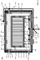
- FIG. 2 schematically illustrates the casing 105.
- the casing 105 is represented in a cross-sectional diagram.
- the casing 105 provides satisfactory protection against electrocution, in addition to being resistant against shock and penetration of objects.
- the casing 105 has an interior space 201 in which the battery 104 can be fitted.
- the casing 105 comprising a plurality of walls 202-205 that encapsulate the interior space 201. These walls include a bottom wall 202, a top wall 203, and two side walls 204, 205, which will be referred to individually as left side wall 204 and right side wall 205 for reasons of convenience. There may be two further side walls, a front wall and a rear wall, which are not visible in FIG. 2 .
- the top wall 203 forms a primary lid part 206 of the casing 105, which is detachably fastened to a primary lid receiving part 207 that includes the bottom wall 202 and the two side walls 204, 205.
- the top wall 203 comprises a secondary lid part 208 and a secondary lid receiving part 209, which are detachably fastened to each other.
- the secondary lid part 208 is a lid-forming portion of the top wall 203.
- the secondary lid receiving part 209 is a remaining, lid receiving portion of the top wall 203.
- the left side wall 204 comprises an assembly of wall elements 210-213 arranged as layers.
- This assembly includes a protective wall element 210, which comprises electrically conductive material, and a set of electrically insulating wall elements 211, 212.
- the set of electrically insulating wall elements 211, 212 are located between the protective wall element 210 and the interior space 201.
- the others walls, including the bottom wall 202, the top wall 203, and right side wall 205 have a similar structure.
- the protective wall element 210 should preferably be relatively lightweight for reasons mentioned hereinbefore. Yet, the protective wall element 210 should preferably confer sufficient mechanical strength to the casing 105, so that the casing 105 can be part of the chassis 101 of the electrically propelled vehicle 100 illustrated in FIG. 1 .
- the chassis 101 should be able to resist to forces of acceleration and, to a certain extent, to forces that may occur in an accident.
- the protective wall element 210 may be carbon fiber-based.
- the protective wall element 210 may have a layered structure that includes carbon fibers.
- the protective wall element 210 may comprise a core layer in the form of a honeycomb structure panel of relatively lightweight metal, such as, for example, aluminum, or an alloy. This core layer may be sandwiched between two carbon fiber layers that comprise carbon fibers embedded in a resin, such as, for example, an epoxy resin.
- a structure can indeed be relatively lightweight and provide sufficient mechanical strength.
- the set of electrically insulating wall elements 211, 212 may comprise a flexible electrically insulating wall element 211 and a rigid electrically insulating wall element 212.
- the rigid electrically insulating wall element 212 is located between the flexible electrically insulating wall element 211 and the interior space 201. This implies that the flexible electrically insulating wall element 211 is sandwiched between the protective wall element 210 and the rigid electrically insulating wall element 212.
- the flexible electrically insulating wall element 211 may comprise wool-like electrically insulating material, such as, for example, Calcium-Magnesium-Silicate wool, or Calcium-Magnesium-Zirconium-Silicate wool, or a combination of both.
- wool-like electrically insulating material such as, for example, Calcium-Magnesium-Silicate wool, or Calcium-Magnesium-Zirconium-Silicate wool, or a combination of both.
- These examples of wool-like electrically insulating material are commercialized under the name "Superwool TM ", Superwool being a trademark of The Morgan Crucible Company plc.
- the rigid electrically insulating wall element 212 may comprise electrically insulating fibers, such as, for example, glass fibers, or aramid fibers.
- a fiber of so-called S2 glass can be a suitable choice.
- Kevlar ® is an example of a suitable aramid fiber, Kevlar being a registered trademark of E. I. du Pont de Nemours and Company or its affiliates.
- the set of electrically insulating wall elements 211, 212 should be sufficiently thick to prevent dielectric breakdown. Dielectric breakdown, which causes arcing, may potentially occur due to the relatively high output voltage of the battery 104.
- the set of electrically insulating wall elements 211, 212 should therefore preferably have a thickness that is greater than a critical thickness at which a dielectric breakdown would occur if a maximum output voltage of the battery 104 were applied to the assembly of wall elements 210-213.
- An appropriate thickness of the set of electrically insulating wall elements 211, 212 can be determined by means of a dielectric test.
- the standard IEC 60664-1 : 2007 defines a suitable dielectric test. Such a dielectric test can reveal a level of electrical insulation that the set of electrically insulating wall elements 211, 212 provides for a given thickness.
- the assembly of wall elements 210-213 includes an EMC shield 213, EMC being an acronym of Electro Magnetic Compatibility.
- EMC being an acronym of Electro Magnetic Compatibility.
- the casing 105 may include this particular shield because the protective wall element 210 may not provide sufficient EMC shielding, although this wall element comprises conductive material.
- the EMC shield 213 is located between the protective wall element 210 and the set of electrically insulating wall elements 211, 212.
- the set of electrically insulating wall elements 211, 212 thus form a barrier between the EMC shield 213 and the battery 104. This prevents the EMC shield 213 from causing a short circuit in the battery 104 in case, for example, a battery cell breaks away from the battery 104 due to, for example, a shock.
- the battery cell will collide with the set of electrically insulating wall elements 211, 212, rather than with the EMC shield 213, or another conductive part that could cause a short circuit.
- the EMC shield 213 may comprise an electrically conductive fabric.
- FIG. 2 illustrates an embodiment in which the various protective wall elements 210 are covered with the electrically conductive fabric on their respective inner sides.
- the electrically conductive fabric may comprise fibers, such as, for example, polyester fibers coated with an electrically conductive material, such as, for example, Nickel.
- the casing 105 comprises a primary interconnection member 214 that equipotentially bonds together the EMC shield 213 in the primary lid part 206, which is formed by the top wall 203, and the EMC shield 213 in the primary lid receiving part 207, which includes the two side walls 204, 205.
- the primary interconnection member 214 is provided with a primary shield connector 215.
- the primary shield connector 215 allows equipotentially bonding the primary interconnection member 214 to a ground terminal 200, as schematically illustrated in FIG. 2 .
- the EMC shield 213 is thereby also equipotentially bonded to the ground terminal 200. Equipotential bonding is achieved by means of a conductive path having relatively low impedance, which typically involves use of relatively wide and thick conductive elements.
- the primary lid part 206 has a circumferential rim 216 over which the EMC shield 213 extends.
- the primary lid receiving part 207 also has a circumferential rim 217 over which the EMC shield 213 extends.
- FIG. 2 illustrates a state in which the primary lid part 206 and the primary lid receiving part 207 are fastened to each other. In this state, the circumferential rim 216 of the primary lid part 206 and the circumferential rim 217 of the primary lid receiving part 207 face each other.
- the primary interconnection member 214 is sandwiched between the aforementioned extending portions of the EMC shield 213, which comprise the electrically conductive fabric in this example.
- the electrically conductive fabric on the circumferential rim 216 of the primary lid part 206 is pressed against the primary interconnection member 214.
- the set of electrically insulating wall elements 211, 212 may have a structure that is different from the general structure described hereinbefore. Near the circumferential rim 216, the set of electrically insulating wall elements 211, 212 may comprise the rigid electrically insulating wall element 212 only, as illustrated in FIG. 2 . In the structure near the circumferential rim 216, the rigid electrically insulating wall element 212 is significantly thicker than in the general structure. This ensures a satisfactory degree of electrical insulation.
- the structure of the set of electrically insulating wall elements 211, 212 also differs from the general structure in a manner as described hereinbefore. It can be further noted that the circumferential rim 217 of the primary lid receiving part 207 comprises a flange-like extension 218 alongside the protective wall element 210 of the left side wall 204 and the right side wall 205. This flange like extension 218 may comprise a same material as the rigid electrically insulating wall element 212.
- the casing 105 comprises a secondary interconnection member 219 that equipotentially bonds together the EMC shield 213 in the secondary lid part 208 and the EMC shield 213 in the secondary lid receiving part 209, which parts form part of the top wall 203.
- the secondary interconnection member 219 is provided with a secondary shield connector 220 that allows equipotentially bonding the secondary interconnection member 219 to a ground terminal 200, as schematically illustrated in FIG. 2 .
- the remarks hereinbefore with regard to the primary lid part 206 and the primary lid receiving part 207 also generally apply to the secondary lid part 208 and the secondary lid receiving part 209, respectively.
- the secondary interconnection member 219 may press against the conductive fabric that is present on a circumferential rim 221 of the secondary lid part 208, as well as against the conductive fabric that is present on a circumferential rim 222 of the secondary lid receiving part 209, as illustrated in FIG. 2 .
- the casing 105 comprises an interior fastening structure 223 to fasten the battery 104 within the interior space 201.
- the interior fastening structure 223 may comprise, for example, conductive base members 224, 225, studs 226, 227, screws 228-231, and battery cell supports 232, as illustrated in FIG. 2 .
- the battery cell supports 232 may mechanically be interconnected with each other by means of screeds.
- the conductive base members 224, 225, studs 226, 227, screws 228-231 may be of metal. In this figure, two conductive base members 224, 225 are visible, which will be referred to individually as left conductive base member 224 and right conductive base member 225.
- the left conductive base member 224 is fixed in a through hole in the bottom wall 202 and traverses this wall. This implies that an intermediate portion of the left conductive base member 224 is embedded in the assembly of wall elements 210-213 that form the bottom wall 202.
- the right conductive base member 225 is fixed in a recess of the bottom wall 202; which implies that a bottom portion of this member 225 is embedded in the assembly of wall elements 210-213 that from the bottom wall 202.
- the interior fastening structure 223 allows fastening a battery 104 within the interior space 201 so that there is a gap 233 of between the battery 104 and any of the walls that forms the casing 105.
- This gap 233 contributes to providing protection against electrocution.
- the gap 233 is preferably sufficiently wide to prevent a dielectric breakdown in a space between the battery 104 and any of the protective wall elements 210, or the electrically conductive fabric that forms the EMC shield 213.
- the gap 233 may be, for example, at least 1 millimeter (mm).
- the casing 105 comprises a connector box 234 located in a through hole in the assembly of wall elements 210-213 that form the bottom wall 202.
- the connector box 234 comprises a set of connectors 236, 237 that allow electrically connecting the battery 104, which is fitted in the interior space 201 of the casing 105, to an electrical device exterior to the casing 105, such as, for example, the electric motor 103 of the electrically propelled vehicle 100 illustrated in FIG. 1 .
- the connector box 234 comprises a ground connector 237 that allows equipotentially bonding the connector box 234 to the ground terminal 200.
- the left conductive base member 224 and right conductive base member 225 are each equipotentially bonded to the connector box 234, as illustrated in FIG. 2 . Consequently, these conductive base members 224, 225 are equipotentially bonded to the ground terminal 200 if the connector box 234 is equipotentially bonded to the ground terminal 200, as illustrated in FIG. 2 .
- the casing 105 comprises an exterior fastening member 238 that allows fastening the casing 105 to, for example, other structural elements that form part of the chassis 101 of the electrically propelled vehicle 101 illustrated in FIG. 1 .
- the exterior fastening member 238 may be in the form of, for example, a mounting bush, which may have a threaded internal cylindrical wall.
- the exterior fastening member 238 may be electrically conductive because, for example, this element is made of metal.
- the exterior fastening member 238 is anchored in the protective wall element 210. That is, a base portion of the exterior fastening member 238 is embedded in the protective wall element 210. A remaining portion of the exterior fastening member 238 protrudes outwardly from the casing 105 as illustrated in FIG. 2 .
- the fastening member 238 need not be equipotentially bonded to the signal ground terminal 200. This is because this element is relatively strongly electrically insulated from the battery 104, contrary to, for example, the conductive base members 224, 225.
- the set of electrically insulating wall elements 211, 212 provide protecting against an electrical contact between the fastening member 238 and the battery 104 in case of an accident.
- FIG. 3 provides a schematic perspective view of the casing 105.
- like elements are denoted by like reference signs.
- the invention may be applied in numerous types of products or methods that involve a battery fitted within a casing.
- the invention may be applied in any type of battery powered structure or system, which need not be a vehicle.
- vehicle should be understood in a broad sense.
- the term may embrace any type of propelled device, including devices capable of flying.
- the term “battery” should be understood in a broad sense.
- the term may embrace any type of electrical energy source that may potentially cause electrocution.
- the term "set of electrically insulating wall elements” should be understood in a broad sense. Such a set may comprise a single electrically insulating wall element only, such as for example, the rigid electrically insulating wall element described hereinbefore.
Landscapes
- Engineering & Computer Science (AREA)
- Chemical & Material Sciences (AREA)
- General Chemical & Material Sciences (AREA)
- Electrochemistry (AREA)
- Chemical Kinetics & Catalysis (AREA)
- Sustainable Energy (AREA)
- Mechanical Engineering (AREA)
- Transportation (AREA)
- Power Engineering (AREA)
- Life Sciences & Earth Sciences (AREA)
- Sustainable Development (AREA)
- Aviation & Aerospace Engineering (AREA)
- Battery Mounting, Suspending (AREA)
Description
- An aspect of the invention relates to a casing having an interior space in which a battery can be fitted. The casing may be included in, for example, a vehicle for housing a battery capable of electrically propelling the vehicle. Other aspects of the invention relate to an assembly comprising a casing and a battery fitted within the casing, and to an electrically propelled vehicle.
- A vehicle, such as, for example, a car, may be propelled electrically. This requires the vehicle to have an electrical energy source, which is typically in the form of a battery. The battery may be fitted in a protective casing that provides fire protection. There may be a risk that the battery catches fire if, for example, the battery is overcharged or malfunctions otherwise. The protective casing may prevent this fire from reaching combustible material in the vehicle, or even explosive material such as, for example, fuel.
- A protective battery casing should preferably be lightweight for reasons of, for example, power efficiency. Light weight may also contribute to performance, in terms of speed and acceleration. Carbon fiber-based composites are relatively lightweight and relatively heat resistant, and also relatively strong and stiff. A protective battery casing may thus comprise carbon fiber-based composites. For example, a protective battery casing may comprise walls that have a layered structure including carbon fibers in epoxy resin.
- There is a need for a solution that allows satisfactory protection against electrocution.
- In order to better address this need, the following points have been taken into consideration. A battery in an electrically propelled vehicle may provide a relatively high output voltage, which could electrocute a person if he or she were to contact an element receiving this high output voltage. A carbon fiber-based composite may provide some electrical insulation although carbon fibers are electrically conductive. For example, carbon fibers may be embedded in epoxy resin, which can be considered as an electrically insulating material.
- However, a protective battery casing comprising carbon fibers, or another conductive material, may get damaged in, for example, an accident. A wall of the protective battery casing may structurally degrade such that some carbon fibers are at least partially denuded, that is, are no longer embedded in epoxy resin or other insulating material. These denuded carbon fibers may contact the battery directly, or indirectly through a conductive element that electrically contacts the battery. A person who touches the protective battery casing may thus risk touching denuded carbon fibers that electrically contact the battery. These touchable carbon fibers may therefore be under relatively high voltage. There is thus risk of electrocution.
- In accordance with an aspect of the invention, there is provided a casing having an interior space in which a battery can be fitted, the casing comprising a plurality of walls that encapsulate the interior space, whereby a wall comprises an assembly of wall elements arranged as layers, the assembly including:
- a protective wall element comprising electrically conductive material; and
- a set of electrically insulating wall elements located between the protective wall element and the interior space and bounding the interior space, the set of electrically insulating wall elements comprising:
- a flexible electrically insulating wall element; and
- a rigid electrically insulating wall element located between the flexible electrically insulating wall element and the interior space, so that the flexible electrically insulating wall element is sandwiched between the protective wall element and the rigid electrically insulating wall element.
- Other aspects of the invention concern an assembly comprising a casing as defined hereinbefore and a battery fitted within this casing. Yet another aspect of the invention concerns an electrically propelled vehicle comprising a casing as defined hereinbefore.
- In each of these aspects, the set of electrically insulating wall elements provides protection against electrocution following, for example, an accident as described hereinbefore. Moreover, the set of electrically insulating wall elements provide protection against a dielectric breakdown in the casing, which also presents a risk of electrocution. In addition, the set of electrically insulating wall elements may prevent a short circuit in the battery if, for example, a battery cell breaks away due to, for example, a shock. The battery cell will collide with the set of electrically insulating wall elements, rather than with a conductive part that could cause a short circuit.
- An embodiment of the invention may comprise one or more additional features defined in the dependent claims, which are appended to the description.
- For the purpose of illustration, a detailed description of some embodiments of the invention is presented with reference to accompanying drawings.
-
-
FIG. 1 is a block diagram of an electrically propelled vehicle comprising a casing in which a battery can be fitted. -
FIG. 2 is a schematic cross-sectional diagram of the casing. -
FIG. 3 is a schematic perspective view of the casing. -
FIG. 1 schematically illustrates an electricallypropelled vehicle 100, which is represented in a block diagram. The electrically propelledvehicle 100 comprises achassis 101, awheel drive mechanism 102, anelectric motor 103, and abattery 104 that is fitted in acasing 105. Thecasing 105 may form a structural part of thechassis 101 of the electrically propelledvehicle 100. - The electrically propelled
vehicle 100 basically operates as follows. Theelectric motor 103 draws electrical power from thebattery 104, which is fitted in thecasing 105. This allows theelectric motor 103 to deliver mechanical power to thewheel drive mechanism 102, which may set the electrically propelledvehicle 100 in motion, or may keep the electricallypropelled vehicle 100 in motion. - There is a risk that the electrically propelled
vehicle 100 is involved in an accident. Thecasing 105 should therefore preferably be resistant against shock and penetration of objects, which may hit thecasing 105 in an accident. Yet, thecasing 105 should preferably be lightweight for reasons of, for example, power efficiency. Light weight also contributes to performance, in terms of speed and acceleration. - In particular, there is a risk of electrocution when the
battery 104 provides a relatively high output voltage. For example, thebattery 104 may comprise 150 lithium-ion cells arranged in series. Such a cell may provide an output voltage of approximately 3 volt. This implies that thebattery 104 may provide an output voltage in the range of, for example, 300 to 1000 volt. -
FIG. 2 schematically illustrates thecasing 105. Thecasing 105 is represented in a cross-sectional diagram. Thecasing 105 provides satisfactory protection against electrocution, in addition to being resistant against shock and penetration of objects. - The
casing 105 has aninterior space 201 in which thebattery 104 can be fitted. Thecasing 105 comprising a plurality of walls 202-205 that encapsulate theinterior space 201. These walls include abottom wall 202, atop wall 203, and twoside walls left side wall 204 andright side wall 205 for reasons of convenience. There may be two further side walls, a front wall and a rear wall, which are not visible inFIG. 2 . - The
top wall 203 forms aprimary lid part 206 of thecasing 105, which is detachably fastened to a primarylid receiving part 207 that includes thebottom wall 202 and the twoside walls top wall 203 comprises asecondary lid part 208 and a secondarylid receiving part 209, which are detachably fastened to each other. In fact, thesecondary lid part 208 is a lid-forming portion of thetop wall 203. The secondarylid receiving part 209 is a remaining, lid receiving portion of thetop wall 203. - The
left side wall 204 comprises an assembly of wall elements 210-213 arranged as layers. This assembly includes aprotective wall element 210, which comprises electrically conductive material, and a set of electrically insulatingwall elements wall elements protective wall element 210 and theinterior space 201. The others walls, including thebottom wall 202, thetop wall 203, andright side wall 205 have a similar structure. - The
protective wall element 210 should preferably be relatively lightweight for reasons mentioned hereinbefore. Yet, theprotective wall element 210 should preferably confer sufficient mechanical strength to thecasing 105, so that thecasing 105 can be part of thechassis 101 of the electrically propelledvehicle 100 illustrated inFIG. 1 . Thechassis 101 should be able to resist to forces of acceleration and, to a certain extent, to forces that may occur in an accident. - The
protective wall element 210 may be carbon fiber-based. For example, theprotective wall element 210 may have a layered structure that includes carbon fibers. For example, theprotective wall element 210 may comprise a core layer in the form of a honeycomb structure panel of relatively lightweight metal, such as, for example, aluminum, or an alloy. This core layer may be sandwiched between two carbon fiber layers that comprise carbon fibers embedded in a resin, such as, for example, an epoxy resin. Such a structure can indeed be relatively lightweight and provide sufficient mechanical strength. - The set of electrically insulating
wall elements wall element 211 and a rigid electrically insulatingwall element 212. The rigid electrically insulatingwall element 212 is located between the flexible electrically insulatingwall element 211 and theinterior space 201. This implies that the flexible electrically insulatingwall element 211 is sandwiched between theprotective wall element 210 and the rigid electrically insulatingwall element 212. This is a general structure of the set of electrically insulatingwall elements wall element 211 may be thicker than the rigid electrically insulatingwall element 212. - The flexible electrically insulating
wall element 211 may comprise wool-like electrically insulating material, such as, for example, Calcium-Magnesium-Silicate wool, or Calcium-Magnesium-Zirconium-Silicate wool, or a combination of both. These examples of wool-like electrically insulating material are commercialized under the name "Superwool™", Superwool being a trademark of The Morgan Crucible Company plc. - The rigid electrically insulating
wall element 212 may comprise electrically insulating fibers, such as, for example, glass fibers, or aramid fibers. A fiber of so-called S2 glass can be a suitable choice. "Kevlar®" is an example of a suitable aramid fiber, Kevlar being a registered trademark of E. I. du Pont de Nemours and Company or its affiliates. - The set of electrically insulating
wall elements battery 104. The set of electrically insulatingwall elements battery 104 were applied to the assembly of wall elements 210-213. - An appropriate thickness of the set of electrically insulating
wall elements wall elements - The assembly of wall elements 210-213 includes an
EMC shield 213, EMC being an acronym of Electro Magnetic Compatibility. Thecasing 105 may include this particular shield because theprotective wall element 210 may not provide sufficient EMC shielding, although this wall element comprises conductive material. - The
EMC shield 213 is located between theprotective wall element 210 and the set of electrically insulatingwall elements wall elements EMC shield 213 and thebattery 104. This prevents theEMC shield 213 from causing a short circuit in thebattery 104 in case, for example, a battery cell breaks away from thebattery 104 due to, for example, a shock. The battery cell will collide with the set of electrically insulatingwall elements EMC shield 213, or another conductive part that could cause a short circuit. - The
EMC shield 213 may comprise an electrically conductive fabric.FIG. 2 illustrates an embodiment in which the variousprotective wall elements 210 are covered with the electrically conductive fabric on their respective inner sides. The electrically conductive fabric may comprise fibers, such as, for example, polyester fibers coated with an electrically conductive material, such as, for example, Nickel. - The
casing 105 comprises aprimary interconnection member 214 that equipotentially bonds together theEMC shield 213 in theprimary lid part 206, which is formed by thetop wall 203, and theEMC shield 213 in the primarylid receiving part 207, which includes the twoside walls primary interconnection member 214 is provided with aprimary shield connector 215. Theprimary shield connector 215 allows equipotentially bonding theprimary interconnection member 214 to aground terminal 200, as schematically illustrated inFIG. 2 . TheEMC shield 213 is thereby also equipotentially bonded to theground terminal 200. Equipotential bonding is achieved by means of a conductive path having relatively low impedance, which typically involves use of relatively wide and thick conductive elements. - In more detail, the
primary lid part 206 has acircumferential rim 216 over which theEMC shield 213 extends. The primarylid receiving part 207 also has acircumferential rim 217 over which theEMC shield 213 extends.FIG. 2 illustrates a state in which theprimary lid part 206 and the primarylid receiving part 207 are fastened to each other. In this state, thecircumferential rim 216 of theprimary lid part 206 and thecircumferential rim 217 of the primarylid receiving part 207 face each other. - The
primary interconnection member 214 is sandwiched between the aforementioned extending portions of theEMC shield 213, which comprise the electrically conductive fabric in this example. The electrically conductive fabric on thecircumferential rim 216 of theprimary lid part 206 is pressed against theprimary interconnection member 214. The same applies to the electrically conductive fabric on thecircumferential rim 217 of the primarylid receiving part 207, which is also pressed against theprimary interconnection member 214. - Near the
circumferential rim 216 of theprimary lid part 206, the set of electrically insulatingwall elements circumferential rim 216, the set of electrically insulatingwall elements wall element 212 only, as illustrated inFIG. 2 . In the structure near thecircumferential rim 216, the rigid electrically insulatingwall element 212 is significantly thicker than in the general structure. This ensures a satisfactory degree of electrical insulation. - Near the
circumferential rim 217 of the primarylid receiving part 207, the structure of the set of electrically insulatingwall elements circumferential rim 217 of the primarylid receiving part 207 comprises a flange-like extension 218 alongside theprotective wall element 210 of theleft side wall 204 and theright side wall 205. This flange likeextension 218 may comprise a same material as the rigid electrically insulatingwall element 212. - The
casing 105 comprises asecondary interconnection member 219 that equipotentially bonds together theEMC shield 213 in thesecondary lid part 208 and theEMC shield 213 in the secondarylid receiving part 209, which parts form part of thetop wall 203. Thesecondary interconnection member 219 is provided with asecondary shield connector 220 that allows equipotentially bonding thesecondary interconnection member 219 to aground terminal 200, as schematically illustrated inFIG. 2 . - The remarks hereinbefore with regard to the
primary lid part 206 and the primarylid receiving part 207 also generally apply to thesecondary lid part 208 and the secondarylid receiving part 209, respectively. Thesecondary interconnection member 219 may press against the conductive fabric that is present on acircumferential rim 221 of thesecondary lid part 208, as well as against the conductive fabric that is present on acircumferential rim 222 of the secondarylid receiving part 209, as illustrated inFIG. 2 . - The
casing 105 comprises aninterior fastening structure 223 to fasten thebattery 104 within theinterior space 201. Theinterior fastening structure 223 may comprise, for example,conductive base members studs FIG. 2 . The battery cell supports 232 may mechanically be interconnected with each other by means of screeds. Theconductive base members studs conductive base members conductive base member 224 and rightconductive base member 225. - In this example, the left
conductive base member 224 is fixed in a through hole in thebottom wall 202 and traverses this wall. This implies that an intermediate portion of the leftconductive base member 224 is embedded in the assembly of wall elements 210-213 that form thebottom wall 202. The rightconductive base member 225 is fixed in a recess of thebottom wall 202; which implies that a bottom portion of thismember 225 is embedded in the assembly of wall elements 210-213 that from thebottom wall 202. - The
interior fastening structure 223 allows fastening abattery 104 within theinterior space 201 so that there is agap 233 of between thebattery 104 and any of the walls that forms thecasing 105. Thisgap 233 contributes to providing protection against electrocution. Thegap 233 is preferably sufficiently wide to prevent a dielectric breakdown in a space between thebattery 104 and any of theprotective wall elements 210, or the electrically conductive fabric that forms theEMC shield 213. Thegap 233 may be, for example, at least 1 millimeter (mm). - The
casing 105 comprises aconnector box 234 located in a through hole in the assembly of wall elements 210-213 that form thebottom wall 202. Theconnector box 234 comprises a set ofconnectors battery 104, which is fitted in theinterior space 201 of thecasing 105, to an electrical device exterior to thecasing 105, such as, for example, theelectric motor 103 of the electrically propelledvehicle 100 illustrated inFIG. 1 . - The
connector box 234 comprises aground connector 237 that allows equipotentially bonding theconnector box 234 to theground terminal 200. The leftconductive base member 224 and rightconductive base member 225 are each equipotentially bonded to theconnector box 234, as illustrated inFIG. 2 . Consequently, theseconductive base members ground terminal 200 if theconnector box 234 is equipotentially bonded to theground terminal 200, as illustrated inFIG. 2 . - The
casing 105 comprises anexterior fastening member 238 that allows fastening thecasing 105 to, for example, other structural elements that form part of thechassis 101 of the electrically propelledvehicle 101 illustrated inFIG. 1 . Theexterior fastening member 238 may be in the form of, for example, a mounting bush, which may have a threaded internal cylindrical wall. Theexterior fastening member 238 may be electrically conductive because, for example, this element is made of metal. - The
exterior fastening member 238 is anchored in theprotective wall element 210. That is, a base portion of theexterior fastening member 238 is embedded in theprotective wall element 210. A remaining portion of theexterior fastening member 238 protrudes outwardly from thecasing 105 as illustrated inFIG. 2 . - The
fastening member 238 need not be equipotentially bonded to thesignal ground terminal 200. This is because this element is relatively strongly electrically insulated from thebattery 104, contrary to, for example, theconductive base members wall elements member 238 and thebattery 104 in case of an accident. -
FIG. 3 provides a schematic perspective view of thecasing 105. In this figure, like elements are denoted by like reference signs. - The detailed description hereinbefore with reference to the drawings is merely an illustration of the invention and the additional features, which are defined in the claims. The invention can be implemented in numerous different ways. In order to illustrate this, some alternatives are briefly indicated.
- The invention may be applied in numerous types of products or methods that involve a battery fitted within a casing. For example, the invention may be applied in any type of battery powered structure or system, which need not be a vehicle. It should further be noted that the term "vehicle" should be understood in a broad sense. The term may embrace any type of propelled device, including devices capable of flying. The term "battery" should be understood in a broad sense. The term may embrace any type of electrical energy source that may potentially cause electrocution. The term "set of electrically insulating wall elements" should be understood in a broad sense. Such a set may comprise a single electrically insulating wall element only, such as for example, the rigid electrically insulating wall element described hereinbefore.
- In general, there are numerous different ways of implementing the invention, whereby different implementations may have different topologies. In any given topology, a single module may carry out several functions, or several modules may jointly carry out a single function. In this respect, the drawings are very diagrammatic.
- The remarks made hereinbefore demonstrate that the detailed description with reference to the drawings is an illustration of the invention rather than a limitation. The invention can be implemented in numerous alternative ways that are within the scope of the appended claims. All changes that come within the meaning and range of equivalency of the claims are to be embraced within their scope. Any reference sign in a claim should not be construed as limiting the claim. The word "comprising" does not exclude the presence of other elements or steps than those listed in a claim. The word "a" or "an" preceding an element or step does not exclude the presence of a plurality of such elements or steps. The mere fact that respective dependent claims define respective additional features, does not exclude combinations of additional features other than those reflected in the claims.
Claims (14)
- A casing (105) having an interior space (201) in which a battery can be fitted, the casing comprising a plurality of walls (202-205) that encapsulate the interior space, whereby a wall comprises an assembly of wall elements (210-213) arranged as layers, the assembly including:- a protective wall element (210) comprising electrically conductive material; and- a set of electrically insulating wall elements (211, 212) located between the protective wall element and the interior space and bounding the interior space, the set of electrically insulating wall elements comprising:- a flexible electrically insulating wall element (211); and- a rigid electrically insulating wall element (212) located between the flexible electrically insulating wall element and the interior space, so that the flexible electrically insulating wall element is sandwiched between the protective wall element and the rigid electrically insulating wall element.
- A casing according to claim 1, wherein the flexible insulating wall element (211) comprises wool-like electrically insulating material.
- A casing according to any of claims 1 and 2, wherein the rigid insulating wall element (212) comprises electrically insulating fibers.
- A casing according to any of claims 1 to 3, wherein the assembly of wall elements (210-214) includes:- an EMC shield (213) located between the protective wall element (210) and the set of electrically insulating wall elements (211, 212), EMC being an acronym for Electro Magnetic Compatibility.
- A casing according to claim 4, wherein the EMC shield (213) comprises an electrically conductive fabric.
- A casing according to any of claims 4 and 5, the casing comprising a lid part (206) and a lid receiving part (207) adapted to be detachably fastened to each other, the casing comprising an interconnection member (214) adapted to equipotentially bond together the EMC shield (213) in the lid part and the EMC shield in the lid receiving part.
- A casing according to claim 6, wherein the interconnection member (214) is provided with a shield connector (215) adapted to equipotentially bond the interconnection member to a ground terminal (200).
- A casing according to any of claims 1 to 7, the casing comprising an interior fastening structure (223) adapted to fasten a battery (104) within the interior space (201) so that there is a gap (233) between the battery and any of the plurality of walls (202-205) of the casing.
- A casing according to any of claims 1 to 8, the casing comprising a connector box (234) at least partially located in a through hole in the assembly of wall elements (210-213), the connector box comprising a set of connectors (235, 236) adapted to electrically connect a battery (104) that is fitted in the interior space (201) of the casing to an electrical device (103) exterior to the casing, the connector box comprising a ground connector (237) adapted to equipotentially bond the connector box to a ground terminal (200).
- A casing in according to claims 8 and 9, wherein the interior fastening structure (223) comprises a conductive base member (224, 225) of which at least a portion is embedded in the assembly of wall elements (210-213), the conductive base member being equipotentially bonded to the connector box (234).
- A casing in according to any of claims 1 to 10, wherein the casing comprises an exterior fastening member (238) that is electrically conductive, a base portion of the exterior fastening member being embedded in the protective wall element (210), whereby a remaining portion of the exterior fastening member protrudes outwardly from the casing.
- An assembly comprising a casing (105) in according to any of claims 1 to 11 and a battery (104) fitted within the casing, wherein the set of electrically insulating wall elements (111, 112) has a thickness that is greater than a critical thickness at which a dielectric breakdown would occur if a maximum output voltage of the battery were applied to the assembly of wall elements.
- An electrically driven vehicle (100) comprising a casing (105) according to any of the claims 1 to 11.
- An electrically driven vehicle according to claim 13, wherein the casing (105) forms a structural part of a chassis (101) of the electrically driven vehicle.
Priority Applications (1)
| Application Number | Priority Date | Filing Date | Title |
|---|---|---|---|
| EP15703014.9A EP3097598B1 (en) | 2014-01-23 | 2015-01-23 | Protective battery casing |
Applications Claiming Priority (3)
| Application Number | Priority Date | Filing Date | Title |
|---|---|---|---|
| EP14305099 | 2014-01-23 | ||
| PCT/EP2015/051420 WO2015110613A1 (en) | 2014-01-23 | 2015-01-23 | Protective battery casing |
| EP15703014.9A EP3097598B1 (en) | 2014-01-23 | 2015-01-23 | Protective battery casing |
Publications (2)
| Publication Number | Publication Date |
|---|---|
| EP3097598A1 EP3097598A1 (en) | 2016-11-30 |
| EP3097598B1 true EP3097598B1 (en) | 2017-07-26 |
Family
ID=52462293
Family Applications (1)
| Application Number | Title | Priority Date | Filing Date |
|---|---|---|---|
| EP15703014.9A Not-in-force EP3097598B1 (en) | 2014-01-23 | 2015-01-23 | Protective battery casing |
Country Status (3)
| Country | Link |
|---|---|
| US (1) | US10270081B2 (en) |
| EP (1) | EP3097598B1 (en) |
| WO (1) | WO2015110613A1 (en) |
Families Citing this family (9)
| Publication number | Priority date | Publication date | Assignee | Title |
|---|---|---|---|---|
| JP6741436B2 (en) * | 2016-02-10 | 2020-08-19 | 株式会社ゼンリン | Driving support system |
| EP3457455A4 (en) * | 2016-03-16 | 2020-03-11 | Kabushiki Kaisha Toshiba | Battery pack |
| CN110637213B (en) * | 2017-05-16 | 2022-11-11 | 北京骑胜科技有限公司 | System and method for digital path planning |
| CN107380613A (en) * | 2017-07-11 | 2017-11-24 | 铱格斯曼航空科技集团有限公司 | Carbon fibre composite aviation energy reserves case and preparation method |
| WO2019044801A1 (en) * | 2017-08-30 | 2019-03-07 | 本田技研工業株式会社 | Laminate, in-vehicle battery containing body, and method for producing in-vehicle battery containing body |
| DE102018209195A1 (en) * | 2018-06-08 | 2019-12-12 | Bayerische Motoren Werke Aktiengesellschaft | Energy storage for a motor vehicle, motor vehicle and method for producing such energy storage |
| US11962025B2 (en) | 2019-02-08 | 2024-04-16 | Dupont Safety & Construction, Inc. | Fire-retardant insulation suitable for battery cells |
| JP2023511310A (en) | 2020-01-23 | 2023-03-17 | ブレン-トロニクス,インコーポレイテッド | Bulletproof case for rechargeable batteries |
| WO2022203406A1 (en) * | 2021-03-25 | 2022-09-29 | 주식회사 엘지에너지솔루션 | Power storage apparatus |
Family Cites Families (6)
| Publication number | Priority date | Publication date | Assignee | Title |
|---|---|---|---|---|
| EP0090191B1 (en) * | 1982-03-27 | 1986-08-13 | BROWN, BOVERI & CIE Aktiengesellschaft | Thermal insulation |
| DE3345141A1 (en) * | 1983-12-14 | 1985-06-27 | Brown, Boveri & Cie Ag, 6800 Mannheim | THERMAL INSULATION |
| DE4013268A1 (en) * | 1990-04-26 | 1991-10-31 | Abb Patent Gmbh | HIGH TEMPERATURE STORAGE BATTERY |
| BR0317886A (en) * | 2003-01-04 | 2005-12-06 | 3M Innovative Properties Co | Insulating element for a battery pack, insulating and battery pack assemblies, vehicle, and methods for isolating a battery pack in a vehicle and for maintaining a battery pack in a vehicle within a temperature range |
| EP2328206A1 (en) * | 2008-07-16 | 2011-06-01 | Panasonic Corporation | Battery pack |
| US20120100414A1 (en) * | 2010-10-22 | 2012-04-26 | Gm Global Technology Operations, Inc. | Encapsulated emi/rfi shielding for a non-conductive thermosetting plastic composite phev battery cover |
-
2015
- 2015-01-23 EP EP15703014.9A patent/EP3097598B1/en not_active Not-in-force
- 2015-01-23 US US15/113,291 patent/US10270081B2/en not_active Expired - Fee Related
- 2015-01-23 WO PCT/EP2015/051420 patent/WO2015110613A1/en not_active Ceased
Non-Patent Citations (1)
| Title |
|---|
| None * |
Also Published As
| Publication number | Publication date |
|---|---|
| WO2015110613A1 (en) | 2015-07-30 |
| US10270081B2 (en) | 2019-04-23 |
| EP3097598A1 (en) | 2016-11-30 |
| US20170012275A1 (en) | 2017-01-12 |
Similar Documents
| Publication | Publication Date | Title |
|---|---|---|
| US10270081B2 (en) | Protective battery casing | |
| US12251919B2 (en) | Electric vehicle battery pack cover having composite structure | |
| CN211024883U (en) | Fire-proof member, battery pack, and device using battery as power source | |
| JP5970825B2 (en) | undercover | |
| CN102398555B (en) | Discharge device for vehicle | |
| CN106469799B (en) | Combination device for energy storage devices, energy storage devices in particular for motor vehicles and motor vehicles | |
| CN107154470B (en) | Battery pack and vehicle with such a battery pack | |
| CN105408170B (en) | High voltage electrical center with connectorized dividing wall | |
| KR20160002750A (en) | Box section housing motor vehicle power equipment forming electromagnetic screening | |
| WO2004057262A2 (en) | Armor producing an electrical or magnetic field | |
| US11530026B2 (en) | Energy subsystems integrated into structural components of an aircraft | |
| IL294828A (en) | Ballistic resistant case for rechargeable batteries | |
| JP2021512009A (en) | Composite battery housing | |
| US11348736B2 (en) | DC-link capacitor for a vehicle driven by an electric motor | |
| JP2012142126A (en) | Battery | |
| JP2015205596A (en) | Inverter on-vehicle structure and inverter on-vehicle bracket unit | |
| CN102623905A (en) | aircraft electrical box | |
| US10632846B2 (en) | High-voltage device | |
| JP4359200B2 (en) | Power supply for vehicle | |
| US20180236881A1 (en) | Axle carrier for the disposal on an electric motor vehicle, and method for the production of said axle carrier | |
| JP2014143042A (en) | Battery case for vehicle | |
| JP6453643B2 (en) | Protective member for vehicle, electric wire assembly and vehicle door | |
| JP2012006528A (en) | Laminar composite for machine body structures of aircraft and machine body structure of aircraft | |
| CN105322697A (en) | Bearing insulation | |
| KR102522607B1 (en) | Combination structure of battery sensor module for vehicle |
Legal Events
| Date | Code | Title | Description |
|---|---|---|---|
| PUAI | Public reference made under article 153(3) epc to a published international application that has entered the european phase |
Free format text: ORIGINAL CODE: 0009012 |
|
| 17P | Request for examination filed |
Effective date: 20160823 |
|
| AK | Designated contracting states |
Kind code of ref document: A1 Designated state(s): AL AT BE BG CH CY CZ DE DK EE ES FI FR GB GR HR HU IE IS IT LI LT LU LV MC MK MT NL NO PL PT RO RS SE SI SK SM TR |
|
| AX | Request for extension of the european patent |
Extension state: BA ME |
|
| REG | Reference to a national code |
Ref country code: DE Ref legal event code: R079 Ref document number: 602015003771 Country of ref document: DE Free format text: PREVIOUS MAIN CLASS: H01M0002100000 Ipc: H01M0002340000 |
|
| GRAP | Despatch of communication of intention to grant a patent |
Free format text: ORIGINAL CODE: EPIDOSNIGR1 |
|
| STAA | Information on the status of an ep patent application or granted ep patent |
Free format text: STATUS: GRANT OF PATENT IS INTENDED |
|
| RIC1 | Information provided on ipc code assigned before grant |
Ipc: H01M 2/34 20060101AFI20170123BHEP Ipc: H01M 2/10 20060101ALI20170123BHEP |
|
| DAX | Request for extension of the european patent (deleted) | ||
| INTG | Intention to grant announced |
Effective date: 20170208 |
|
| GRAS | Grant fee paid |
Free format text: ORIGINAL CODE: EPIDOSNIGR3 |
|
| GRAA | (expected) grant |
Free format text: ORIGINAL CODE: 0009210 |
|
| STAA | Information on the status of an ep patent application or granted ep patent |
Free format text: STATUS: THE PATENT HAS BEEN GRANTED |
|
| AK | Designated contracting states |
Kind code of ref document: B1 Designated state(s): AL AT BE BG CH CY CZ DE DK EE ES FI FR GB GR HR HU IE IS IT LI LT LU LV MC MK MT NL NO PL PT RO RS SE SI SK SM TR |
|
| REG | Reference to a national code |
Ref country code: GB Ref legal event code: FG4D |
|
| REG | Reference to a national code |
Ref country code: CH Ref legal event code: EP |
|
| REG | Reference to a national code |
Ref country code: AT Ref legal event code: REF Ref document number: 913075 Country of ref document: AT Kind code of ref document: T Effective date: 20170815 |
|
| REG | Reference to a national code |
Ref country code: IE Ref legal event code: FG4D |
|
| REG | Reference to a national code |
Ref country code: DE Ref legal event code: R096 Ref document number: 602015003771 Country of ref document: DE |
|
| REG | Reference to a national code |
Ref country code: NL Ref legal event code: MP Effective date: 20170726 |
|
| REG | Reference to a national code |
Ref country code: LT Ref legal event code: MG4D |
|
| REG | Reference to a national code |
Ref country code: AT Ref legal event code: MK05 Ref document number: 913075 Country of ref document: AT Kind code of ref document: T Effective date: 20170726 |
|
| PG25 | Lapsed in a contracting state [announced via postgrant information from national office to epo] |
Ref country code: NL Free format text: LAPSE BECAUSE OF FAILURE TO SUBMIT A TRANSLATION OF THE DESCRIPTION OR TO PAY THE FEE WITHIN THE PRESCRIBED TIME-LIMIT Effective date: 20170726 Ref country code: HR Free format text: LAPSE BECAUSE OF FAILURE TO SUBMIT A TRANSLATION OF THE DESCRIPTION OR TO PAY THE FEE WITHIN THE PRESCRIBED TIME-LIMIT Effective date: 20170726 Ref country code: SE Free format text: LAPSE BECAUSE OF FAILURE TO SUBMIT A TRANSLATION OF THE DESCRIPTION OR TO PAY THE FEE WITHIN THE PRESCRIBED TIME-LIMIT Effective date: 20170726 Ref country code: NO Free format text: LAPSE BECAUSE OF FAILURE TO SUBMIT A TRANSLATION OF THE DESCRIPTION OR TO PAY THE FEE WITHIN THE PRESCRIBED TIME-LIMIT Effective date: 20171026 Ref country code: LT Free format text: LAPSE BECAUSE OF FAILURE TO SUBMIT A TRANSLATION OF THE DESCRIPTION OR TO PAY THE FEE WITHIN THE PRESCRIBED TIME-LIMIT Effective date: 20170726 Ref country code: FI Free format text: LAPSE BECAUSE OF FAILURE TO SUBMIT A TRANSLATION OF THE DESCRIPTION OR TO PAY THE FEE WITHIN THE PRESCRIBED TIME-LIMIT Effective date: 20170726 Ref country code: AT Free format text: LAPSE BECAUSE OF FAILURE TO SUBMIT A TRANSLATION OF THE DESCRIPTION OR TO PAY THE FEE WITHIN THE PRESCRIBED TIME-LIMIT Effective date: 20170726 |
|
| REG | Reference to a national code |
Ref country code: FR Ref legal event code: PLFP Year of fee payment: 4 |
|
| PG25 | Lapsed in a contracting state [announced via postgrant information from national office to epo] |
Ref country code: RS Free format text: LAPSE BECAUSE OF FAILURE TO SUBMIT A TRANSLATION OF THE DESCRIPTION OR TO PAY THE FEE WITHIN THE PRESCRIBED TIME-LIMIT Effective date: 20170726 Ref country code: IS Free format text: LAPSE BECAUSE OF FAILURE TO SUBMIT A TRANSLATION OF THE DESCRIPTION OR TO PAY THE FEE WITHIN THE PRESCRIBED TIME-LIMIT Effective date: 20171126 Ref country code: BG Free format text: LAPSE BECAUSE OF FAILURE TO SUBMIT A TRANSLATION OF THE DESCRIPTION OR TO PAY THE FEE WITHIN THE PRESCRIBED TIME-LIMIT Effective date: 20171026 Ref country code: PL Free format text: LAPSE BECAUSE OF FAILURE TO SUBMIT A TRANSLATION OF THE DESCRIPTION OR TO PAY THE FEE WITHIN THE PRESCRIBED TIME-LIMIT Effective date: 20170726 Ref country code: LV Free format text: LAPSE BECAUSE OF FAILURE TO SUBMIT A TRANSLATION OF THE DESCRIPTION OR TO PAY THE FEE WITHIN THE PRESCRIBED TIME-LIMIT Effective date: 20170726 Ref country code: ES Free format text: LAPSE BECAUSE OF FAILURE TO SUBMIT A TRANSLATION OF THE DESCRIPTION OR TO PAY THE FEE WITHIN THE PRESCRIBED TIME-LIMIT Effective date: 20170726 Ref country code: GR Free format text: LAPSE BECAUSE OF FAILURE TO SUBMIT A TRANSLATION OF THE DESCRIPTION OR TO PAY THE FEE WITHIN THE PRESCRIBED TIME-LIMIT Effective date: 20171027 |
|
| PG25 | Lapsed in a contracting state [announced via postgrant information from national office to epo] |
Ref country code: DK Free format text: LAPSE BECAUSE OF FAILURE TO SUBMIT A TRANSLATION OF THE DESCRIPTION OR TO PAY THE FEE WITHIN THE PRESCRIBED TIME-LIMIT Effective date: 20170726 Ref country code: CZ Free format text: LAPSE BECAUSE OF FAILURE TO SUBMIT A TRANSLATION OF THE DESCRIPTION OR TO PAY THE FEE WITHIN THE PRESCRIBED TIME-LIMIT Effective date: 20170726 |
|
| REG | Reference to a national code |
Ref country code: DE Ref legal event code: R097 Ref document number: 602015003771 Country of ref document: DE |
|
| PG25 | Lapsed in a contracting state [announced via postgrant information from national office to epo] |
Ref country code: SM Free format text: LAPSE BECAUSE OF FAILURE TO SUBMIT A TRANSLATION OF THE DESCRIPTION OR TO PAY THE FEE WITHIN THE PRESCRIBED TIME-LIMIT Effective date: 20170726 Ref country code: IT Free format text: LAPSE BECAUSE OF FAILURE TO SUBMIT A TRANSLATION OF THE DESCRIPTION OR TO PAY THE FEE WITHIN THE PRESCRIBED TIME-LIMIT Effective date: 20170726 Ref country code: SK Free format text: LAPSE BECAUSE OF FAILURE TO SUBMIT A TRANSLATION OF THE DESCRIPTION OR TO PAY THE FEE WITHIN THE PRESCRIBED TIME-LIMIT Effective date: 20170726 Ref country code: EE Free format text: LAPSE BECAUSE OF FAILURE TO SUBMIT A TRANSLATION OF THE DESCRIPTION OR TO PAY THE FEE WITHIN THE PRESCRIBED TIME-LIMIT Effective date: 20170726 |
|
| PLBE | No opposition filed within time limit |
Free format text: ORIGINAL CODE: 0009261 |
|
| STAA | Information on the status of an ep patent application or granted ep patent |
Free format text: STATUS: NO OPPOSITION FILED WITHIN TIME LIMIT |
|
| 26N | No opposition filed |
Effective date: 20180430 |
|
| PG25 | Lapsed in a contracting state [announced via postgrant information from national office to epo] |
Ref country code: SI Free format text: LAPSE BECAUSE OF FAILURE TO SUBMIT A TRANSLATION OF THE DESCRIPTION OR TO PAY THE FEE WITHIN THE PRESCRIBED TIME-LIMIT Effective date: 20170726 |
|
| REG | Reference to a national code |
Ref country code: CH Ref legal event code: PL |
|
| PG25 | Lapsed in a contracting state [announced via postgrant information from national office to epo] |
Ref country code: LU Free format text: LAPSE BECAUSE OF NON-PAYMENT OF DUE FEES Effective date: 20180123 |
|
| REG | Reference to a national code |
Ref country code: IE Ref legal event code: MM4A |
|
| REG | Reference to a national code |
Ref country code: BE Ref legal event code: MM Effective date: 20180131 |
|
| PG25 | Lapsed in a contracting state [announced via postgrant information from national office to epo] |
Ref country code: LI Free format text: LAPSE BECAUSE OF NON-PAYMENT OF DUE FEES Effective date: 20180131 Ref country code: CH Free format text: LAPSE BECAUSE OF NON-PAYMENT OF DUE FEES Effective date: 20180131 Ref country code: BE Free format text: LAPSE BECAUSE OF NON-PAYMENT OF DUE FEES Effective date: 20180131 |
|
| PG25 | Lapsed in a contracting state [announced via postgrant information from national office to epo] |
Ref country code: IE Free format text: LAPSE BECAUSE OF NON-PAYMENT OF DUE FEES Effective date: 20180123 |
|
| PG25 | Lapsed in a contracting state [announced via postgrant information from national office to epo] |
Ref country code: MC Free format text: LAPSE BECAUSE OF FAILURE TO SUBMIT A TRANSLATION OF THE DESCRIPTION OR TO PAY THE FEE WITHIN THE PRESCRIBED TIME-LIMIT Effective date: 20170726 |
|
| PG25 | Lapsed in a contracting state [announced via postgrant information from national office to epo] |
Ref country code: MT Free format text: LAPSE BECAUSE OF NON-PAYMENT OF DUE FEES Effective date: 20180123 |
|
| PG25 | Lapsed in a contracting state [announced via postgrant information from national office to epo] |
Ref country code: TR Free format text: LAPSE BECAUSE OF FAILURE TO SUBMIT A TRANSLATION OF THE DESCRIPTION OR TO PAY THE FEE WITHIN THE PRESCRIBED TIME-LIMIT Effective date: 20170726 |
|
| PG25 | Lapsed in a contracting state [announced via postgrant information from national office to epo] |
Ref country code: PT Free format text: LAPSE BECAUSE OF FAILURE TO SUBMIT A TRANSLATION OF THE DESCRIPTION OR TO PAY THE FEE WITHIN THE PRESCRIBED TIME-LIMIT Effective date: 20170726 |
|
| PG25 | Lapsed in a contracting state [announced via postgrant information from national office to epo] |
Ref country code: CY Free format text: LAPSE BECAUSE OF FAILURE TO SUBMIT A TRANSLATION OF THE DESCRIPTION OR TO PAY THE FEE WITHIN THE PRESCRIBED TIME-LIMIT Effective date: 20170726 Ref country code: MK Free format text: LAPSE BECAUSE OF NON-PAYMENT OF DUE FEES Effective date: 20170726 Ref country code: HU Free format text: LAPSE BECAUSE OF FAILURE TO SUBMIT A TRANSLATION OF THE DESCRIPTION OR TO PAY THE FEE WITHIN THE PRESCRIBED TIME-LIMIT; INVALID AB INITIO Effective date: 20150123 Ref country code: RO Free format text: LAPSE BECAUSE OF FAILURE TO SUBMIT A TRANSLATION OF THE DESCRIPTION OR TO PAY THE FEE WITHIN THE PRESCRIBED TIME-LIMIT Effective date: 20170726 |
|
| PG25 | Lapsed in a contracting state [announced via postgrant information from national office to epo] |
Ref country code: AL Free format text: LAPSE BECAUSE OF FAILURE TO SUBMIT A TRANSLATION OF THE DESCRIPTION OR TO PAY THE FEE WITHIN THE PRESCRIBED TIME-LIMIT Effective date: 20170726 |
|
| REG | Reference to a national code |
Ref country code: DE Ref legal event code: R079 Ref document number: 602015003771 Country of ref document: DE Free format text: PREVIOUS MAIN CLASS: H01M0002340000 Ipc: H01M0050572000 |
|
| PGFP | Annual fee paid to national office [announced via postgrant information from national office to epo] |
Ref country code: FR Payment date: 20210201 Year of fee payment: 7 |
|
| PGFP | Annual fee paid to national office [announced via postgrant information from national office to epo] |
Ref country code: GB Payment date: 20210201 Year of fee payment: 7 Ref country code: DE Payment date: 20210204 Year of fee payment: 7 |
|
| REG | Reference to a national code |
Ref country code: DE Ref legal event code: R119 Ref document number: 602015003771 Country of ref document: DE |
|
| GBPC | Gb: european patent ceased through non-payment of renewal fee |
Effective date: 20220123 |
|
| PG25 | Lapsed in a contracting state [announced via postgrant information from national office to epo] |
Ref country code: GB Free format text: LAPSE BECAUSE OF NON-PAYMENT OF DUE FEES Effective date: 20220123 Ref country code: DE Free format text: LAPSE BECAUSE OF NON-PAYMENT OF DUE FEES Effective date: 20220802 |
|
| PG25 | Lapsed in a contracting state [announced via postgrant information from national office to epo] |
Ref country code: FR Free format text: LAPSE BECAUSE OF NON-PAYMENT OF DUE FEES Effective date: 20220131 |