EP3096384A1 - Fuel cell system and controlling method thereof - Google Patents
Fuel cell system and controlling method thereof Download PDFInfo
- Publication number
- EP3096384A1 EP3096384A1 EP16169768.5A EP16169768A EP3096384A1 EP 3096384 A1 EP3096384 A1 EP 3096384A1 EP 16169768 A EP16169768 A EP 16169768A EP 3096384 A1 EP3096384 A1 EP 3096384A1
- Authority
- EP
- European Patent Office
- Prior art keywords
- fuel cell
- signal
- cell stack
- flow rate
- fuel
- Prior art date
- Legal status (The legal status is an assumption and is not a legal conclusion. Google has not performed a legal analysis and makes no representation as to the accuracy of the status listed.)
- Granted
Links
Images


Classifications
-
- H—ELECTRICITY
- H01—ELECTRIC ELEMENTS
- H01M—PROCESSES OR MEANS, e.g. BATTERIES, FOR THE DIRECT CONVERSION OF CHEMICAL ENERGY INTO ELECTRICAL ENERGY
- H01M8/00—Fuel cells; Manufacture thereof
- H01M8/04—Auxiliary arrangements, e.g. for control of pressure or for circulation of fluids
- H01M8/04298—Processes for controlling fuel cells or fuel cell systems
- H01M8/04992—Processes for controlling fuel cells or fuel cell systems characterised by the implementation of mathematical or computational algorithms, e.g. feedback control loops, fuzzy logic, neural networks or artificial intelligence
-
- H—ELECTRICITY
- H01—ELECTRIC ELEMENTS
- H01M—PROCESSES OR MEANS, e.g. BATTERIES, FOR THE DIRECT CONVERSION OF CHEMICAL ENERGY INTO ELECTRICAL ENERGY
- H01M8/00—Fuel cells; Manufacture thereof
- H01M8/04—Auxiliary arrangements, e.g. for control of pressure or for circulation of fluids
- H01M8/04298—Processes for controlling fuel cells or fuel cell systems
- H01M8/04694—Processes for controlling fuel cells or fuel cell systems characterised by variables to be controlled
- H01M8/04746—Pressure; Flow
- H01M8/04753—Pressure; Flow of fuel cell reactants
-
- H—ELECTRICITY
- H01—ELECTRIC ELEMENTS
- H01M—PROCESSES OR MEANS, e.g. BATTERIES, FOR THE DIRECT CONVERSION OF CHEMICAL ENERGY INTO ELECTRICAL ENERGY
- H01M8/00—Fuel cells; Manufacture thereof
- H01M8/04—Auxiliary arrangements, e.g. for control of pressure or for circulation of fluids
- H01M8/04298—Processes for controlling fuel cells or fuel cell systems
- H01M8/04313—Processes for controlling fuel cells or fuel cell systems characterised by the detection or assessment of variables; characterised by the detection or assessment of failure or abnormal function
- H01M8/04537—Electric variables
- H01M8/04574—Current
- H01M8/04589—Current of fuel cell stacks
-
- H—ELECTRICITY
- H01—ELECTRIC ELEMENTS
- H01M—PROCESSES OR MEANS, e.g. BATTERIES, FOR THE DIRECT CONVERSION OF CHEMICAL ENERGY INTO ELECTRICAL ENERGY
- H01M8/00—Fuel cells; Manufacture thereof
- H01M8/04—Auxiliary arrangements, e.g. for control of pressure or for circulation of fluids
- H01M8/04082—Arrangements for control of reactant parameters, e.g. pressure or concentration
- H01M8/04089—Arrangements for control of reactant parameters, e.g. pressure or concentration of gaseous reactants
-
- H—ELECTRICITY
- H01—ELECTRIC ELEMENTS
- H01M—PROCESSES OR MEANS, e.g. BATTERIES, FOR THE DIRECT CONVERSION OF CHEMICAL ENERGY INTO ELECTRICAL ENERGY
- H01M8/00—Fuel cells; Manufacture thereof
- H01M8/04—Auxiliary arrangements, e.g. for control of pressure or for circulation of fluids
- H01M8/04298—Processes for controlling fuel cells or fuel cell systems
- H01M8/04305—Modeling, demonstration models of fuel cells, e.g. for training purposes
-
- H—ELECTRICITY
- H01—ELECTRIC ELEMENTS
- H01M—PROCESSES OR MEANS, e.g. BATTERIES, FOR THE DIRECT CONVERSION OF CHEMICAL ENERGY INTO ELECTRICAL ENERGY
- H01M8/00—Fuel cells; Manufacture thereof
- H01M8/04—Auxiliary arrangements, e.g. for control of pressure or for circulation of fluids
- H01M8/04298—Processes for controlling fuel cells or fuel cell systems
- H01M8/04313—Processes for controlling fuel cells or fuel cell systems characterised by the detection or assessment of variables; characterised by the detection or assessment of failure or abnormal function
- H01M8/04537—Electric variables
- H01M8/04604—Power, energy, capacity or load
-
- H—ELECTRICITY
- H01—ELECTRIC ELEMENTS
- H01M—PROCESSES OR MEANS, e.g. BATTERIES, FOR THE DIRECT CONVERSION OF CHEMICAL ENERGY INTO ELECTRICAL ENERGY
- H01M8/00—Fuel cells; Manufacture thereof
- H01M8/04—Auxiliary arrangements, e.g. for control of pressure or for circulation of fluids
- H01M8/04298—Processes for controlling fuel cells or fuel cell systems
- H01M8/04313—Processes for controlling fuel cells or fuel cell systems characterised by the detection or assessment of variables; characterised by the detection or assessment of failure or abnormal function
- H01M8/04537—Electric variables
- H01M8/04604—Power, energy, capacity or load
- H01M8/04619—Power, energy, capacity or load of fuel cell stacks
-
- H—ELECTRICITY
- H01—ELECTRIC ELEMENTS
- H01M—PROCESSES OR MEANS, e.g. BATTERIES, FOR THE DIRECT CONVERSION OF CHEMICAL ENERGY INTO ELECTRICAL ENERGY
- H01M8/00—Fuel cells; Manufacture thereof
- H01M8/04—Auxiliary arrangements, e.g. for control of pressure or for circulation of fluids
- H01M8/04298—Processes for controlling fuel cells or fuel cell systems
- H01M8/04313—Processes for controlling fuel cells or fuel cell systems characterised by the detection or assessment of variables; characterised by the detection or assessment of failure or abnormal function
- H01M8/04664—Failure or abnormal function
- H01M8/04679—Failure or abnormal function of fuel cell stacks
-
- H—ELECTRICITY
- H01—ELECTRIC ELEMENTS
- H01M—PROCESSES OR MEANS, e.g. BATTERIES, FOR THE DIRECT CONVERSION OF CHEMICAL ENERGY INTO ELECTRICAL ENERGY
- H01M8/00—Fuel cells; Manufacture thereof
- H01M8/04—Auxiliary arrangements, e.g. for control of pressure or for circulation of fluids
- H01M8/04298—Processes for controlling fuel cells or fuel cell systems
- H01M8/04694—Processes for controlling fuel cells or fuel cell systems characterised by variables to be controlled
- H01M8/04701—Temperature
-
- H—ELECTRICITY
- H01—ELECTRIC ELEMENTS
- H01M—PROCESSES OR MEANS, e.g. BATTERIES, FOR THE DIRECT CONVERSION OF CHEMICAL ENERGY INTO ELECTRICAL ENERGY
- H01M8/00—Fuel cells; Manufacture thereof
- H01M8/04—Auxiliary arrangements, e.g. for control of pressure or for circulation of fluids
- H01M8/04298—Processes for controlling fuel cells or fuel cell systems
- H01M8/04694—Processes for controlling fuel cells or fuel cell systems characterised by variables to be controlled
- H01M8/04746—Pressure; Flow
-
- H—ELECTRICITY
- H01—ELECTRIC ELEMENTS
- H01M—PROCESSES OR MEANS, e.g. BATTERIES, FOR THE DIRECT CONVERSION OF CHEMICAL ENERGY INTO ELECTRICAL ENERGY
- H01M8/00—Fuel cells; Manufacture thereof
- H01M8/04—Auxiliary arrangements, e.g. for control of pressure or for circulation of fluids
- H01M8/04298—Processes for controlling fuel cells or fuel cell systems
- H01M8/04694—Processes for controlling fuel cells or fuel cell systems characterised by variables to be controlled
- H01M8/04746—Pressure; Flow
- H01M8/04761—Pressure; Flow of fuel cell exhausts
-
- H—ELECTRICITY
- H01—ELECTRIC ELEMENTS
- H01M—PROCESSES OR MEANS, e.g. BATTERIES, FOR THE DIRECT CONVERSION OF CHEMICAL ENERGY INTO ELECTRICAL ENERGY
- H01M8/00—Fuel cells; Manufacture thereof
- H01M8/04—Auxiliary arrangements, e.g. for control of pressure or for circulation of fluids
- H01M8/04298—Processes for controlling fuel cells or fuel cell systems
- H01M8/04694—Processes for controlling fuel cells or fuel cell systems characterised by variables to be controlled
- H01M8/04858—Electric variables
- H01M8/04865—Voltage
-
- H—ELECTRICITY
- H01—ELECTRIC ELEMENTS
- H01M—PROCESSES OR MEANS, e.g. BATTERIES, FOR THE DIRECT CONVERSION OF CHEMICAL ENERGY INTO ELECTRICAL ENERGY
- H01M8/00—Fuel cells; Manufacture thereof
- H01M8/04—Auxiliary arrangements, e.g. for control of pressure or for circulation of fluids
- H01M8/04298—Processes for controlling fuel cells or fuel cell systems
- H01M8/04694—Processes for controlling fuel cells or fuel cell systems characterised by variables to be controlled
- H01M8/04858—Electric variables
- H01M8/04895—Current
-
- H—ELECTRICITY
- H01—ELECTRIC ELEMENTS
- H01M—PROCESSES OR MEANS, e.g. BATTERIES, FOR THE DIRECT CONVERSION OF CHEMICAL ENERGY INTO ELECTRICAL ENERGY
- H01M8/00—Fuel cells; Manufacture thereof
- H01M8/04—Auxiliary arrangements, e.g. for control of pressure or for circulation of fluids
- H01M8/04298—Processes for controlling fuel cells or fuel cell systems
- H01M8/04694—Processes for controlling fuel cells or fuel cell systems characterised by variables to be controlled
- H01M8/04858—Electric variables
- H01M8/04895—Current
- H01M8/0491—Current of fuel cell stacks
-
- H—ELECTRICITY
- H01—ELECTRIC ELEMENTS
- H01M—PROCESSES OR MEANS, e.g. BATTERIES, FOR THE DIRECT CONVERSION OF CHEMICAL ENERGY INTO ELECTRICAL ENERGY
- H01M8/00—Fuel cells; Manufacture thereof
- H01M8/10—Fuel cells with solid electrolytes
- H01M8/1007—Fuel cells with solid electrolytes with both reactants being gaseous or vaporised
-
- H—ELECTRICITY
- H01—ELECTRIC ELEMENTS
- H01M—PROCESSES OR MEANS, e.g. BATTERIES, FOR THE DIRECT CONVERSION OF CHEMICAL ENERGY INTO ELECTRICAL ENERGY
- H01M8/00—Fuel cells; Manufacture thereof
- H01M8/10—Fuel cells with solid electrolytes
- H01M8/12—Fuel cells with solid electrolytes operating at high temperature, e.g. with stabilised ZrO2 electrolyte
- H01M2008/1293—Fuel cells with solid oxide electrolytes
-
- Y—GENERAL TAGGING OF NEW TECHNOLOGICAL DEVELOPMENTS; GENERAL TAGGING OF CROSS-SECTIONAL TECHNOLOGIES SPANNING OVER SEVERAL SECTIONS OF THE IPC; TECHNICAL SUBJECTS COVERED BY FORMER USPC CROSS-REFERENCE ART COLLECTIONS [XRACs] AND DIGESTS
- Y02—TECHNOLOGIES OR APPLICATIONS FOR MITIGATION OR ADAPTATION AGAINST CLIMATE CHANGE
- Y02E—REDUCTION OF GREENHOUSE GAS [GHG] EMISSIONS, RELATED TO ENERGY GENERATION, TRANSMISSION OR DISTRIBUTION
- Y02E60/00—Enabling technologies; Technologies with a potential or indirect contribution to GHG emissions mitigation
- Y02E60/30—Hydrogen technology
- Y02E60/50—Fuel cells
Definitions
- This disclosure relates generally to the field of fuel cells, and more particularly to a fuel cell system and a method for controlling the fuel cell system.
- Fuel cells are an electro-chemical device that make use of electro-chemical reaction between a fuel, such as hydrogen, and an oxidizer, such as oxygen contained in the surrounding air, to generate electrical power.
- the fuel cells are advantageous in low contamination, high efficiency and high power density.
- PEMFC proton exchange membrane fuel cell
- the fuel cell will deteriorate with time when operated over an extended period of time.
- the degradation of the fuel cell includes faulty electrical contacts, cracks in electrolyte plates, coating faults, material faults, leakage, increased internal resistance, flooding or drying in membrane and etc.
- Factors affecting the life of the fuel cell may include geometrical design, material design, process flow design and operating control design. How to reduce the degradation of the fuel cell and prolong the life of the fuel cell by operation control is still a challenge.
- a fuel cell system comprising a fuel cell stack coupled to a load for providing power, a gas delivery system coupled to the fuel cell stack for providing fuel and oxygen to the fuel cell stack, and a control system.
- the control system comprises a forward controller for generating a desired control instruction signal based on a command from the load, and a correction controller for generating a control correction signal to avoid violating operational constraints of the fuel cell stack based on at least one measured signal from the fuel cell system.
- the control system generates a control signal based on the desired control instruction signal and the control correction signal, and controls the gas delivery system based on the generated control signal so as to ensure the fuel cell stack is operated within safe operating limits.
- a method for controlling a fuel cell system comprises: generating a desired control instruction signal based on a command from a load in a fuel cell system, wherein the fuel cell system comprises a fuel cell stack coupled to the load for providing power, and a gas delivery system coupled to the fuel cell stack for providing fuel and oxygen to the fuel cell stack; generating a control correction signal to avoid violating operational constraints of the fuel cell stack based on at least one measured signal from the fuel cell system; generating a control signal based on the desired control instruction signal and the control correction signal; and controlling the gas delivery system based on the generated control signal so as to ensure the fuel cell stack is operated within safe operating limits.
- FIG. 1 illustrates a schematic block diagram of a fuel cell system in accordance with an embodiment of the present invention.
- a fuel cell system 100 in accordance with an embodiment of the present invention includes a fuel cell stack 1 coupled to a load 2 for providing power, a gas delivery system 3 coupled to the fuel cell stack 1 for providing fuel and oxygen to the fuel cell stack 1, and a control system 4 for controlling the gas delivery system 3.
- the control system 4 includes a forward controller 41 and a correction controller 42.
- the forward controller 41 is configured to generate a desired control instruction signal S1 based on a command C L from the load 2.
- the correction controller 42 is configured to generate a control correction signal S2 based on at least one measured signal S M from the fuel cell system 100.
- the control correction signal S2 is configured to avoid violating operational constraints of the fuel cell stack 1.
- the control system 4 is configured to generate a control signal S3 based on the desired control instruction signal S1 and the control correction signal S2, and control the gas delivery system 3 based on the generated control signal S3 so as to ensure the fuel cell stack 1 of the present invention is operated within safe operating limits.
- the fuel cell system 100 of the present invention can address effectively different operational constraints of the fuel cell stack 1 in a uniform manner, and hold some key variables affecting the life of the fuel cell stack 1 in safe boundaries, so that the fuel cell system 100 of the present invention can effectively ensure that the fuel cell stack 1 is operated with its safe operating limits in condition of meeting normal operation of the fuel cell system 100.
- the fuel cell system 100 of the present invention can prolong the life of the fuel cell stack 1, and have simplified design and lower cost.
- the fuel cell stack 1 includes a series of fuel cells stacked together.
- the fuel usually hydrogen and the air, usually oxygen, are reacted in the fuel cell stack 1.
- the fuel cell stack 1 converts hydrogen and oxygen into water to produce electricity and heat.
- the fuel cell stack 1 of the present invention may be applicable for both high temperature fuel cells, such as a solid oxide fuel cell (SOFC), a molten carbonate fuel cell (MCFC) and etc., and low temperature fuel cells, such as a proton exchange membrane fuel cell (PEMFC), a direct methanol fuel cell (DMFC) and etc.
- SOFC solid oxide fuel cell
- MCFC molten carbonate fuel cell
- DMFC direct methanol fuel cell
- the fuel cell stack comprises a series of solid oxide fuel cells.
- Each of the solid oxide fuel cells has an anode, a cathode, solid electrolyte between the anode and the cathode and an interconnect.
- the solid electrolyte is most commonly a ceramic material called yttria-stabilized zirconia (YSZ) that conducts negative oxygen ions at sufficient high temperature (typically above 500 °C).
- the operational constraints of the fuel cell stack 1 are user specified operational constraints associated with the life of the fuel cell stack 1.
- the operational constraints of the fuel cell stack 1 may comprise at least one of the following constraints: a voltage of a single fuel cell of the fuel cell stack 1, a resistance of the fuel cell stack 1, a pressure difference between anode gas pressure and cathode gas pressure of the fuel cell stack 1, maximal temperature difference in the fuel cell stack 1, an oxygen excess ratio which is a ratio of the oxygen supplied to a cathode of the fuel cell stack 1 to the actually consumed oxygen, a fuel excess ratio which is a ratio of the fuel supplied to an anode of the fuel cell stack 1 to the actually consumed fuel, a pressure difference between ambient pressure where the fuel cell system 100 is located and anode inlet gas pressure of the fuel cell stack 1, a pressure difference between the ambient pressure and cathode inlet gas pressure of the fuel cell stack 1, cross leakage between the anode and the cathode, cross leakage between the anode and ambient environment where the fuel cell system 100 is located, and cross leak
- the voltage of the single fuel cell of the fuel cell stack 1 may be in the range of about 0.55 to 1.0V.
- the pressure difference between the anode gas pressure and the cathode gas pressure of the fuel cell stack 1 may be in the range of about -40Kpa to 40Kpa.
- the maximal temperature difference in the fuel cell stack 1 may be in the range of about -40Kpa to 40Kpa.
- the oxygen excess ratio may be in the range of 2 to 6.
- the fuel excess ratio may be in the range of 1.5 to 6.
- the pressure difference between ambient pressure and the anode inlet gas pressure of the fuel cell stack 1 may be in the range of about 0Kpa to 40Kpa.
- the pressure difference between the ambient pressure and the cathode inlet gas pressure of the fuel cell stack 1 may be in the range of 0Kpa to 40Kpa. But it should be understood that the number and the specific values of the operational constraints of the fuel cell stack 1 may be correspondingly adjusted in advance by the users according to practically operational conditions of the fuel cell stack 1.
- the at least one measured signal S M may comprise at least one of the following signals: an anode inlet gas pressure, an anode outlet gas pressure, a cathode inlet gas pressure, a cathode outlet gas pressure, an anode inlet flow rate, an anode outlet flow rate, a cathode inlet flow rate, and a cathode outlet flow rate of the fuel cell stack 1, one and more temperature measurements of the fuel cell stack 1, a voltage of a single fuel cell of the fuel cell stack 1, a current of the fuel cell stack 1, and ambient temperature, ambient pressure, and ambient humidity where the fuel cell system 100 is located.
- the at least one measured signal S M of the present invention should not be limited to the above signals, and may also include other signals which are not mentioned herein.
- the fuel cell system 100 of the present invention further comprises an exhaust discharge system 5 coupled to the fuel cell stack 1 for discharging exhaust.
- the reactant and unreacted gas are discharged as the exhaust through the exhaust discharge system 5.
- the exhaust discharge system 5 includes an anode discharge module 51 for discharging fuel exhaust and a cathode discharge module 52 for discharging air exhaust.
- the control system 4 further comprises a summator 43.
- the summator 43 is configured to sum the desired control instruction signal S1 and the control correction signal S2 to generate the control signal S3.
- the control system 4 may further comprise a selector.
- the selector may be configured to select a maximum of the desired control instruction signal S1 and the control correction signal S2. The selected maximum is regarded as the control signal S3.
- the selector may be also configured to select a minimum of the desired control instruction signal S1 and the control correction signal S2. The selected minimum is regarded as the control signal S3.
- the gas delivery system 3 includes a fuel flow governor 31 and an air flow governor 32.
- the fuel flow governor 31 is configured to adjust fuel flow rate which is supplied to the fuel cell stack 1.
- the air flow governor 32 is configured to adjust air flow rate which is supplied to the fuel cell stack 1.
- FIG. 2 illustrates a schematic block diagram of the control system 4 of the present invention.
- the desired control instruction signal S1 comprises a desired fuel flow rate instruction signal S11 and a desired air flow rate instruction signal S12
- the control correction signal S2 comprises a fuel flow rate correction signal S21 and an air flow rate correction signal S22.
- the correction controller 42 generates the fuel flow rate correction signal S21 and adds the generated fuel flow rate correction signal S21 to the desired fuel flow rate instruction signal S11 so as to obtain the fuel flow rate signal S31
- the correction controller 42 generates the air flow rate correction signal S22 and adds the generated air flow rate correction signal S22 to the desired air flow rate instruction signal S12 so as to obtain the air flow rate signal S32.
- the control signal S3 comprises the fuel flow rate signal S31 and the air flow rate signal S32.
- the summator 43 includes a first summator 431 and a second summator 432.
- the first summator 431 sums the desired fuel flow rate instruction signal S11 and the fuel flow rate correction signal S21 to generate the fuel flow rate signal S31.
- the second summator 432 sums the desired air flow rate instruction signal S12 and the air flow rate correction signal S22 to generate the air flow rate signal S32.
- the command C L from the load 2 comprises a power command C L .
- FIG. 3 illustrates a schematic block diagram of the forward controller 41 of the present invention.
- the forward controller 41 includes a scheduler 411 and a converter 412.
- the scheduler 411 generates a scheduled current signal S IS based on the power command C L .
- the scheduler 411 generates the scheduled current signal S IS based on the power command C L and further based on a current measurement S I from the fuel cell stack 1.
- the scheduler 411 may include a current calculation module 4111, a compensation module 4112 and a third summator 4113.
- the current calculation module 4111 calculates a baseline current signal S IB based on the power command C L to meet the power command C L .
- the compensation module 4112 generates a compensation current signal S IC based on the current measurement S I .
- the third summator 4113 sums the baseline current signal S IB and the compensation current signal S IC to generate the scheduled current signal S IS .
- the converter 412 converts the scheduled current signal S IS to the desired control instruction signal S1 by multiplying a stoichiometry ratio.
- the desired control instruction signal S1 comprises the desired fuel flow rate instruction signal S11 and the desired air flow rate instruction signal S12.
- the correction controller 42 of the present invention uses a model predictive control to address the operational constraints of the fuel cell stack 1.
- the correction controller 42 is configured to predict whether the desired control instruction signal S1 will violate the operational constraints of the fuel cell stack 1 based on the at least one measured signal S M .
- the correction controller 42 of the present invention generates the control correction signal S2 and adds the generated control correction signal S2 to the desired control instruction signal S1.
- the control correction signal S2 comprises the fuel flow rate correction signal S21 and the air flow rate correction signal S22.
- the fuel flow rate correction signal S21 is generated and added to the desired fuel flow rate instruction signal S11
- the air flow rate correction signal S22 is generated and added to the desired air flow rate instruction signal S12.
- the fuel cell system 100 of the present invention may at least have beneficial technical effects as following:
- the fuel cell system 100 of the present invention can also provide a generic fuel cell life control solution which could deal with multiple, interactive constraints in one framework, and have the strong constraint handling capability which can deal with a fewer manipulated variables (for example, only two variables, fuel flow rate and air flow rate) to meeting the more constraints.
- the fuel cell system 100 of the present invention can have a broader application field ranging from low temperature fuel cells to high temperature fuel cells.
- the fuel cell system 100 of the present invention is easy to operate.
- the fuel cell system 100 of the present invention includes two separate controlling modules, that is, the forward controller 41 and the correction controller 42 which can be tuned and subjected to troubleshooting procedures separately, with a clear physical meaning.
- the forward controller 41 and the correction controller 42 which can be tuned and subjected to troubleshooting procedures separately, with a clear physical meaning.
- operators without a deep control background can also use the fuel cell system 100 of the present invention.
- FIG. 4 illustrates a flow chart of a method for controlling the fuel cell system 100 in accordance with an embodiment of the present invention. As shown in FIG. 4 in conjunction with FIGS. 1-3 , a method for controlling the fuel cell system 100 in accordance with an embodiment of the present invention includes the steps as following:
- step B1 further comprises the steps as following:
- FIG. 5 is a flow chart illustrating the steps in generating the scheduled current signal S IS based on both the power command C L and the current measurement S I from the fuel cell stack 1 according to the method of FIG. 4 .
- the step B11 further comprises the following steps:
- the scheduled current signal S IS is converted to the desired control instruction signal S1 by multiplying a stoichiometry ratio.
- the scheduled current signal S IS is converted to the desired fuel flow rate instruction signal S11 and the desired air flow rate instruction signal S12.
- the operational constraints of the fuel cell stack 1 are pre-specified by users.
- the operational constraints of the fuel cell stack 1 are associated with the life of the fuel cell stack 1.
- the operational constraints of the fuel cell stack 1 may comprise but not be limited to be at least one of the following constraints: a voltage of a single fuel cell of the fuel cell stack 1, a resistance of the fuel cell stack 1, a pressure difference between anode gas pressure and cathode gas pressure of the fuel cell stack 1, maximal temperature difference in the fuel cell stack 1, an oxygen excess ratio which is a ratio of the oxygen supplied to a cathode of the fuel cell stack 1 to the actually consumed oxygen, a fuel excess ratio which is a ratio of the fuel supplied to an anode of the fuel cell stack 1 to the actually consumed fuel, a pressure difference between ambient pressure where the fuel cell system 100 is located and anode inlet gas pressure of the fuel cell stack 1, a pressure difference between the ambient pressure and cathode inlet gas pressure of the fuel cell stack 1, cross leakage between the anode and the cathode,
- a predictive model is pre-established.
- the predictive model is configured to describe the behavior of the fuel cell stack 1.
- block B4 it is predicted whether the desired control instruction signal S1 will violate the operational constraints of the fuel cell stack 1 from the predictive model based on the at least one measured signal S M .
- the at least one measured signal S M may for example, comprise but not be limited to, at least one of the following signals: an anode inlet gas pressure, an anode outlet gas pressure, a cathode inlet gas pressure, a cathode outlet gas pressure, an anode inlet flow rate, an anode outlet flow rate, a cathode inlet flow rate, and a cathode outlet flow rate of the fuel cell stack 1, one and more temperature measurements of the fuel cell stack 1, a voltage of a single fuel cell of the fuel cell stack 1, a current of the fuel cell stack 1, and ambient temperature, ambient pressure, and ambient humidity where the fuel cell system 100 is located. If the predicted result is "yes", the step goes to block B5.
- control correction signal S2 when it is predicted that the desired control instruction signal S1 will violate the operational constraints of the fuel cell stack 1, a control correction signal S2 is generated and added to the desired control instruction signal S1.
- the control correction signal S2 includes a fuel flow rate correction signal S21 and an air flow rate correction signal S22.
- the fuel flow rate correction signal S21 is generated and added to the desired fuel flow rate instruction signal S 11.
- the air flow rate correction signal S22 is generated and added to the desired air flow rate instruction signal S12.
- the fuel flow rate correction signal S21 and the air flow rate correction signal S22 are respectively generated and added to the desired fuel flow rate instruction signal S11 and the desired air flow rate instruction signal S12.
- a control signal S3 is generated based on the desired control instruction signal S 1 and the control correction signal S2.
- the control signal S3 includes a fuel flow rate signal S31 and an air flow rate signal S32.
- the fuel flow rate signal S31 is generated based on the desired fuel flow rate instruction signal S11 and the fuel flow rate correction signal S21
- the air flow rate signal S32 is generated based on the desired air flow rate instruction signal S12 and the air flow rate correction signal S22.
- control signal S3 is generated by summing the desired control instruction signal S 1 and the control correction signal S2.
- fuel flow rate signal S31 of the control signal S3 is generated by summing the desired fuel flow rate instruction signal S11 and the fuel flow rate correction signal S21
- the air flow rate signal S32 of the control signal S3 is generated by summing the desired air flow rate instruction signal S12 and the air flow rate correction signal S22.
- the gas delivery system 3 is controlled based on the generated control signal S3 so as to ensure the fuel cell stack 1 is operated within safe operating limits.
- the generated control signal S3 includes the fuel flow rate signal S31 and the air flow rate signal S32, so the fuel flow rate signal S31 and the air flow rate signal S32 are configured to respectively control the fuel flow governor 31 and the air flow governor 32 (see FIG. 1 ) of the gas delivery system 3.
- the fuel flow governor 31 will adjust the fuel flow rate which is supplied to the fuel cell stack 1 according to the fuel flow rate signal S31
- the air flow governor 32 will adjust the air flow rate which is supplied to the fuel cell stack 1 according to the air flow rate signal S32.
- the method for controlling the fuel cell system 100 of the present invention can address effectively different operational constraints of the fuel cell stack 1 in a uniform manner, and hold some key variables affecting the life of the fuel cell stack 1 in safe boundaries, so that the controlling method of the present invention can effectively ensure that the fuel cell stack 1 is operated with its safe operating limits in condition of meeting normal operation of the fuel cell system 100.
- the controlling method of the present invention can prolong the life of the fuel cell stack 1, simplify the design of the fuel cell system 100 and reduce the cost of the fuel cell system 100.
- the method for controlling the fuel cell system 100 of the present invention has the similar beneficial technical effects to that described in the fuel cell system 100 above.
Landscapes
- Engineering & Computer Science (AREA)
- General Chemical & Material Sciences (AREA)
- Manufacturing & Machinery (AREA)
- Sustainable Development (AREA)
- Sustainable Energy (AREA)
- Chemical & Material Sciences (AREA)
- Chemical Kinetics & Catalysis (AREA)
- Electrochemistry (AREA)
- Life Sciences & Earth Sciences (AREA)
- Automation & Control Theory (AREA)
- Health & Medical Sciences (AREA)
- Artificial Intelligence (AREA)
- Computing Systems (AREA)
- Evolutionary Computation (AREA)
- Fuzzy Systems (AREA)
- Medical Informatics (AREA)
- Software Systems (AREA)
- Theoretical Computer Science (AREA)
- Fuel Cell (AREA)
Abstract
Description
- This disclosure relates generally to the field of fuel cells, and more particularly to a fuel cell system and a method for controlling the fuel cell system.
- Fuel cells are an electro-chemical device that make use of electro-chemical reaction between a fuel, such as hydrogen, and an oxidizer, such as oxygen contained in the surrounding air, to generate electrical power. The fuel cells are advantageous in low contamination, high efficiency and high power density. Thus, developments and researches are intensively devoted to the fuel cell field for exploitation of the utilization thereof. A variety of fuel cells are available, among which proton exchange membrane fuel cell (PEMFC) is the most prospective one due to the advantages of low operation temperature, fast activation and high power density with respect to unit weight and volume.
- However, it is known that the fuel cell will deteriorate with time when operated over an extended period of time. The degradation of the fuel cell includes faulty electrical contacts, cracks in electrolyte plates, coating faults, material faults, leakage, increased internal resistance, flooding or drying in membrane and etc. Factors affecting the life of the fuel cell may include geometrical design, material design, process flow design and operating control design. How to reduce the degradation of the fuel cell and prolong the life of the fuel cell by operation control is still a challenge.
- In one aspect of embodiments of the present invention, a fuel cell system is provided. The fuel cell system comprises a fuel cell stack coupled to a load for providing power, a gas delivery system coupled to the fuel cell stack for providing fuel and oxygen to the fuel cell stack, and a control system. The control system comprises a forward controller for generating a desired control instruction signal based on a command from the load, and a correction controller for generating a control correction signal to avoid violating operational constraints of the fuel cell stack based on at least one measured signal from the fuel cell system. The control system generates a control signal based on the desired control instruction signal and the control correction signal, and controls the gas delivery system based on the generated control signal so as to ensure the fuel cell stack is operated within safe operating limits.
- In another aspect of embodiments of the present invention, a method for controlling a fuel cell system is provided. The method comprises: generating a desired control instruction signal based on a command from a load in a fuel cell system, wherein the fuel cell system comprises a fuel cell stack coupled to the load for providing power, and a gas delivery system coupled to the fuel cell stack for providing fuel and oxygen to the fuel cell stack; generating a control correction signal to avoid violating operational constraints of the fuel cell stack based on at least one measured signal from the fuel cell system; generating a control signal based on the desired control instruction signal and the control correction signal; and controlling the gas delivery system based on the generated control signal so as to ensure the fuel cell stack is operated within safe operating limits.
- Various features, aspects, and advantages of the present disclosure will become better understood when the following detailed description is read with reference to the accompanying drawings in which like characters represent like parts throughout the drawings, wherein:
-
FIG. 1 is a schematic block diagram of a fuel cell system in accordance with an embodiment of the present invention; -
FIG. 2 is a schematic block diagram of a control system ofFIG. 1 ; -
FIG. 3 is a schematic block diagram of a forward controller ofFIG. 2 ; -
FIG. 4 is a flow chart of a method for controlling a fuel cell system in accordance with an embodiment of the present invention; and -
FIG. 5 is a flow chart illustrating the steps in generating a scheduled current signal according to the method ofFIG. 4 . - Embodiments of the present disclosure will be described herein below with reference to the accompanying drawings. In the following description, well-known functions or constructions are not described in detail to avoid obscuring the disclosure in unnecessary detail.
- Unless defined otherwise, technical and scientific terms used herein have the same meaning as is commonly understood by one of ordinary skill in the art to which this disclosure belongs. The terms "first", "second", and the like, as used herein do not denote any order, quantity, or importance, but rather are used to distinguish one element from another. Also, the terms "a" and "an" do not denote a limitation of quantity, but rather denote the presence of at least one of the referenced items. The term "or" is meant to be inclusive and mean either or all of the listed items. The use of "including," "comprising" or "having" and variations thereof herein are meant to encompass the items listed thereafter and equivalents thereof as well as additional items. Further, the phrase "based on" means "based at least in part on".
-
FIG. 1 illustrates a schematic block diagram of a fuel cell system in accordance with an embodiment of the present invention. As shown inFIG. 1 , afuel cell system 100 in accordance with an embodiment of the present invention includes afuel cell stack 1 coupled to aload 2 for providing power, agas delivery system 3 coupled to thefuel cell stack 1 for providing fuel and oxygen to thefuel cell stack 1, and acontrol system 4 for controlling thegas delivery system 3. Thecontrol system 4 includes aforward controller 41 and acorrection controller 42. Theforward controller 41 is configured to generate a desired control instruction signal S1 based on a command CL from theload 2. Thecorrection controller 42 is configured to generate a control correction signal S2 based on at least one measured signal SM from thefuel cell system 100. The control correction signal S2 is configured to avoid violating operational constraints of thefuel cell stack 1. Thecontrol system 4 is configured to generate a control signal S3 based on the desired control instruction signal S1 and the control correction signal S2, and control thegas delivery system 3 based on the generated control signal S3 so as to ensure thefuel cell stack 1 of the present invention is operated within safe operating limits. - The
fuel cell system 100 of the present invention can address effectively different operational constraints of thefuel cell stack 1 in a uniform manner, and hold some key variables affecting the life of thefuel cell stack 1 in safe boundaries, so that thefuel cell system 100 of the present invention can effectively ensure that thefuel cell stack 1 is operated with its safe operating limits in condition of meeting normal operation of thefuel cell system 100. Thefuel cell system 100 of the present invention can prolong the life of thefuel cell stack 1, and have simplified design and lower cost. - The
fuel cell stack 1 includes a series of fuel cells stacked together. The fuel, usually hydrogen and the air, usually oxygen, are reacted in thefuel cell stack 1. Thefuel cell stack 1 converts hydrogen and oxygen into water to produce electricity and heat. Thefuel cell stack 1 of the present invention may be applicable for both high temperature fuel cells, such as a solid oxide fuel cell (SOFC), a molten carbonate fuel cell (MCFC) and etc., and low temperature fuel cells, such as a proton exchange membrane fuel cell (PEMFC), a direct methanol fuel cell (DMFC) and etc. For example, in the case that the fuel cell system of the present invention is a solid oxide fuel cell type system, the fuel cell stack comprises a series of solid oxide fuel cells. Each of the solid oxide fuel cells has an anode, a cathode, solid electrolyte between the anode and the cathode and an interconnect. The solid electrolyte is most commonly a ceramic material called yttria-stabilized zirconia (YSZ) that conducts negative oxygen ions at sufficient high temperature (typically above 500 °C). - The operational constraints of the
fuel cell stack 1 are user specified operational constraints associated with the life of thefuel cell stack 1. The operational constraints of thefuel cell stack 1 may comprise at least one of the following constraints: a voltage of a single fuel cell of thefuel cell stack 1, a resistance of thefuel cell stack 1, a pressure difference between anode gas pressure and cathode gas pressure of thefuel cell stack 1, maximal temperature difference in thefuel cell stack 1, an oxygen excess ratio which is a ratio of the oxygen supplied to a cathode of thefuel cell stack 1 to the actually consumed oxygen, a fuel excess ratio which is a ratio of the fuel supplied to an anode of thefuel cell stack 1 to the actually consumed fuel, a pressure difference between ambient pressure where thefuel cell system 100 is located and anode inlet gas pressure of thefuel cell stack 1, a pressure difference between the ambient pressure and cathode inlet gas pressure of thefuel cell stack 1, cross leakage between the anode and the cathode, cross leakage between the anode and ambient environment where thefuel cell system 100 is located, and cross leakage between the cathode and the ambient environment. However, the operational constraints of thefuel cell stack 1 of the present invention should not be limited to the above constraints, and may also include other constraints which are not mentioned herein. - For example, in some embodiments, the voltage of the single fuel cell of the
fuel cell stack 1 may be in the range of about 0.55 to 1.0V. The pressure difference between the anode gas pressure and the cathode gas pressure of thefuel cell stack 1 may be in the range of about -40Kpa to 40Kpa. The maximal temperature difference in thefuel cell stack 1 may be in the range of about -40Kpa to 40Kpa. The oxygen excess ratio may be in the range of 2 to 6. The fuel excess ratio may be in the range of 1.5 to 6. The pressure difference between ambient pressure and the anode inlet gas pressure of thefuel cell stack 1 may be in the range of about 0Kpa to 40Kpa. The pressure difference between the ambient pressure and the cathode inlet gas pressure of thefuel cell stack 1 may be in the range of 0Kpa to 40Kpa. But it should be understood that the number and the specific values of the operational constraints of thefuel cell stack 1 may be correspondingly adjusted in advance by the users according to practically operational conditions of thefuel cell stack 1. - The at least one measured signal SM may comprise at least one of the following signals: an anode inlet gas pressure, an anode outlet gas pressure, a cathode inlet gas pressure, a cathode outlet gas pressure, an anode inlet flow rate, an anode outlet flow rate, a cathode inlet flow rate, and a cathode outlet flow rate of the
fuel cell stack 1, one and more temperature measurements of thefuel cell stack 1, a voltage of a single fuel cell of thefuel cell stack 1, a current of thefuel cell stack 1, and ambient temperature, ambient pressure, and ambient humidity where thefuel cell system 100 is located. However, the at least one measured signal SM of the present invention should not be limited to the above signals, and may also include other signals which are not mentioned herein. - Continuing to refer to
FIG. 1 , thefuel cell system 100 of the present invention further comprises anexhaust discharge system 5 coupled to thefuel cell stack 1 for discharging exhaust. The reactant and unreacted gas are discharged as the exhaust through theexhaust discharge system 5. Theexhaust discharge system 5 includes ananode discharge module 51 for discharging fuel exhaust and acathode discharge module 52 for discharging air exhaust. - With reference to
FIG. 1 , in an embodiment, thecontrol system 4 further comprises asummator 43. Thesummator 43 is configured to sum the desired control instruction signal S1 and the control correction signal S2 to generate the control signal S3. However, thesummator 43 is illustrated only as an example of the present invention, and in fact, thecontrol system 4 of the present invention should not be limited to include thesummator 43. In another embodiment of the present invention, thecontrol system 4 may further comprise a selector. For example, the selector may be configured to select a maximum of the desired control instruction signal S1 and the control correction signal S2. The selected maximum is regarded as the control signal S3. Alternatively, the selector may be also configured to select a minimum of the desired control instruction signal S1 and the control correction signal S2. The selected minimum is regarded as the control signal S3. - The
gas delivery system 3 includes afuel flow governor 31 and anair flow governor 32. Thefuel flow governor 31 is configured to adjust fuel flow rate which is supplied to thefuel cell stack 1. Theair flow governor 32 is configured to adjust air flow rate which is supplied to thefuel cell stack 1. -
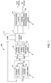
FIG. 2 illustrates a schematic block diagram of thecontrol system 4 of the present invention. As shown inFIG. 2 , in an embodiment, the desired control instruction signal S1 comprises a desired fuel flow rate instruction signal S11 and a desired air flow rate instruction signal S12, and correspondingly, the control correction signal S2 comprises a fuel flow rate correction signal S21 and an air flow rate correction signal S22. Thecorrection controller 42 generates the fuel flow rate correction signal S21 and adds the generated fuel flow rate correction signal S21 to the desired fuel flow rate instruction signal S11 so as to obtain the fuel flow rate signal S31, and thecorrection controller 42 generates the air flow rate correction signal S22 and adds the generated air flow rate correction signal S22 to the desired air flow rate instruction signal S12 so as to obtain the air flow rate signal S32. Thus, the control signal S3 comprises the fuel flow rate signal S31 and the air flow rate signal S32. - In this embodiment, with reference to
FIG. 2 , thesummator 43 includes afirst summator 431 and asecond summator 432. Thefirst summator 431 sums the desired fuel flow rate instruction signal S11 and the fuel flow rate correction signal S21 to generate the fuel flow rate signal S31. Thesecond summator 432 sums the desired air flow rate instruction signal S12 and the air flow rate correction signal S22 to generate the air flow rate signal S32. - In one embodiment, the command CL from the
load 2 comprises a power command CL. -
FIG. 3 illustrates a schematic block diagram of theforward controller 41 of the present invention. As shown inFIG. 3 , theforward controller 41 includes ascheduler 411 and aconverter 412. In one embodiment, thescheduler 411 generates a scheduled current signal SIS based on the power command CL. In another embodiment, thescheduler 411 generates the scheduled current signal SIS based on the power command CL and further based on a current measurement SI from thefuel cell stack 1. As an example, thescheduler 411 may include acurrent calculation module 4111, acompensation module 4112 and athird summator 4113. Thecurrent calculation module 4111 calculates a baseline current signal SIB based on the power command CL to meet the power command CL. Thecompensation module 4112 generates a compensation current signal SIC based on the current measurement SI. Thethird summator 4113 sums the baseline current signal SIB and the compensation current signal SIC to generate the scheduled current signal SIS. Theconverter 412 converts the scheduled current signal SIS to the desired control instruction signal S1 by multiplying a stoichiometry ratio. In one embodiment, the desired control instruction signal S1 comprises the desired fuel flow rate instruction signal S11 and the desired air flow rate instruction signal S12. - With reference to
FIGS. 1 and2 , thecorrection controller 42 of the present invention uses a model predictive control to address the operational constraints of thefuel cell stack 1. Thecorrection controller 42 is configured to predict whether the desired control instruction signal S1 will violate the operational constraints of thefuel cell stack 1 based on the at least one measured signal SM. When it is predicted that the desired control instruction signal S1 will violate the operational constraints of thefuel cell stack 1, thecorrection controller 42 of the present invention generates the control correction signal S2 and adds the generated control correction signal S2 to the desired control instruction signal S1. In one embodiment, the control correction signal S2 comprises the fuel flow rate correction signal S21 and the air flow rate correction signal S22. The fuel flow rate correction signal S21 is generated and added to the desired fuel flow rate instruction signal S11, and the air flow rate correction signal S22 is generated and added to the desired air flow rate instruction signal S12. - The
fuel cell system 100 of the present invention may at least have beneficial technical effects as following: - The
fuel cell system 100 of the present invention can provide a low cost solution for extending fuel cell life since there is no need for additional hardware, process flow or material change. - The
fuel cell system 100 of the present invention can also provide a generic fuel cell life control solution which could deal with multiple, interactive constraints in one framework, and have the strong constraint handling capability which can deal with a fewer manipulated variables (for example, only two variables, fuel flow rate and air flow rate) to meeting the more constraints. - The
fuel cell system 100 of the present invention can have a broader application field ranging from low temperature fuel cells to high temperature fuel cells. - The
fuel cell system 100 of the present invention is easy to operate. Thefuel cell system 100 of the present invention includes two separate controlling modules, that is, theforward controller 41 and thecorrection controller 42 which can be tuned and subjected to troubleshooting procedures separately, with a clear physical meaning. Thus, operators without a deep control background can also use thefuel cell system 100 of the present invention. -
FIG. 4 illustrates a flow chart of a method for controlling thefuel cell system 100 in accordance with an embodiment of the present invention. As shown inFIG. 4 in conjunction withFIGS. 1-3 , a method for controlling thefuel cell system 100 in accordance with an embodiment of the present invention includes the steps as following: - In block B1, a desired control instruction signal S1 is generated based on the command CL from the
load 2 in thefuel cell system 100 above. In this embodiment, a desired fuel flow rate instruction signal S11 and a desired air flow rate instruction signal S12 are generated based on the command CL from theload 2. Thus, the desired control instruction signal S1 includes the desired fuel flow rate instruction signal S11 and the desired air flow rate instruction signal S12. In one embodiment, the command CL from theload 2 may comprise a power command CL. - When the command CL from the
load 2 is the power command CL, the step B1 further comprises the steps as following: - In block B11, a scheduled current signal SIS is generated. In one embodiment, the scheduled current signal SIS is generated based on the power command CL. In another embodiment, the scheduled current signal SIS is generated based on the power command CL, and further based on a current measurement SI from the
fuel cell stack 1. -
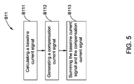
FIG. 5 is a flow chart illustrating the steps in generating the scheduled current signal SIS based on both the power command CL and the current measurement SI from thefuel cell stack 1 according to the method ofFIG. 4 . As shown inFIG. 5 , the step B11 further comprises the following steps: - In block B111, a baseline current signal SIB is calculated based on the power command CL to meet the power command CL.
- In block B112, a compensation current signal SIC is generated based on the current measurement SI.
- In block B113, the baseline current signal SIB and the compensation current signal SIC are summed (added) to generate the scheduled current signal SIS.
- Returning now to
FIG. 4 , in block B12, the scheduled current signal SIS is converted to the desired control instruction signal S1 by multiplying a stoichiometry ratio. In this embodiment, the scheduled current signal SIS is converted to the desired fuel flow rate instruction signal S11 and the desired air flow rate instruction signal S12. - In block B2, the operational constraints of the
fuel cell stack 1 are pre-specified by users. The operational constraints of thefuel cell stack 1 are associated with the life of thefuel cell stack 1. For example, the operational constraints of thefuel cell stack 1 may comprise but not be limited to be at least one of the following constraints: a voltage of a single fuel cell of thefuel cell stack 1, a resistance of thefuel cell stack 1, a pressure difference between anode gas pressure and cathode gas pressure of thefuel cell stack 1, maximal temperature difference in thefuel cell stack 1, an oxygen excess ratio which is a ratio of the oxygen supplied to a cathode of thefuel cell stack 1 to the actually consumed oxygen, a fuel excess ratio which is a ratio of the fuel supplied to an anode of thefuel cell stack 1 to the actually consumed fuel, a pressure difference between ambient pressure where thefuel cell system 100 is located and anode inlet gas pressure of thefuel cell stack 1, a pressure difference between the ambient pressure and cathode inlet gas pressure of thefuel cell stack 1, cross leakage between the anode and the cathode, cross leakage between the anode and ambient environment where thefuel cell system 100 is located, and cross leakage between the cathode and the ambient environment. - In block B3, a predictive model is pre-established. The predictive model is configured to describe the behavior of the
fuel cell stack 1. - In block B4, it is predicted whether the desired control instruction signal S1 will violate the operational constraints of the
fuel cell stack 1 from the predictive model based on the at least one measured signal SM. In this embodiment, it is predicted whether any one or both of the desired fuel flow rate instruction signal S11 and the desired air flow rate instruction signal S12 will violate the operational constraints of thefuel cell stack 1 from the predictive model based on the at least one measured signal SM. The at least one measured signal SM may for example, comprise but not be limited to, at least one of the following signals: an anode inlet gas pressure, an anode outlet gas pressure, a cathode inlet gas pressure, a cathode outlet gas pressure, an anode inlet flow rate, an anode outlet flow rate, a cathode inlet flow rate, and a cathode outlet flow rate of thefuel cell stack 1, one and more temperature measurements of thefuel cell stack 1, a voltage of a single fuel cell of thefuel cell stack 1, a current of thefuel cell stack 1, and ambient temperature, ambient pressure, and ambient humidity where thefuel cell system 100 is located. If the predicted result is "yes", the step goes to block B5. - In block B5, when it is predicted that the desired control instruction signal S1 will violate the operational constraints of the
fuel cell stack 1, a control correction signal S2 is generated and added to the desired control instruction signal S1. In this embodiment, the control correction signal S2 includes a fuel flow rate correction signal S21 and an air flow rate correction signal S22. - For example, when it is predicted that the desired fuel flow rate instruction signal S11 of the desired control instruction signal S1 will violate the operational constraints of the
fuel cell stack 1, the fuel flow rate correction signal S21 is generated and added to the desired fuel flow rateinstruction signal S 11. When it is predicted that the desired air flow rate instruction signal S12 of the desired control instruction signal S1 will violate the operational constraints of thefuel cell stack 1, the air flow rate correction signal S22 is generated and added to the desired air flow rate instruction signal S12. When it is predicted that both the desired fuel flow rate instruction signal S11 and the desired air flow rate instruction signal S12 of the desired control instruction signal S1 will violate the operational constraints of thefuel cell stack 1, the fuel flow rate correction signal S21 and the air flow rate correction signal S22 are respectively generated and added to the desired fuel flow rate instruction signal S11 and the desired air flow rate instruction signal S12. - In block B6, a control signal S3 is generated based on the desired control
instruction signal S 1 and the control correction signal S2. In this embodiment, the control signal S3 includes a fuel flow rate signal S31 and an air flow rate signal S32. Specifically, the fuel flow rate signal S31 is generated based on the desired fuel flow rate instruction signal S11 and the fuel flow rate correction signal S21, and the air flow rate signal S32 is generated based on the desired air flow rate instruction signal S12 and the air flow rate correction signal S22. - In one embodiment, the control signal S3 is generated by summing the desired control
instruction signal S 1 and the control correction signal S2. In detail, the fuel flow rate signal S31 of the control signal S3 is generated by summing the desired fuel flow rate instruction signal S11 and the fuel flow rate correction signal S21, and the air flow rate signal S32 of the control signal S3 is generated by summing the desired air flow rate instruction signal S12 and the air flow rate correction signal S22. - In block B7, the
gas delivery system 3 is controlled based on the generated control signal S3 so as to ensure thefuel cell stack 1 is operated within safe operating limits. The generated control signal S3 includes the fuel flow rate signal S31 and the air flow rate signal S32, so the fuel flow rate signal S31 and the air flow rate signal S32 are configured to respectively control thefuel flow governor 31 and the air flow governor 32 (seeFIG. 1 ) of thegas delivery system 3. Thefuel flow governor 31 will adjust the fuel flow rate which is supplied to thefuel cell stack 1 according to the fuel flow rate signal S31, and theair flow governor 32 will adjust the air flow rate which is supplied to thefuel cell stack 1 according to the air flow rate signal S32. - The method for controlling the
fuel cell system 100 of the present invention can address effectively different operational constraints of thefuel cell stack 1 in a uniform manner, and hold some key variables affecting the life of thefuel cell stack 1 in safe boundaries, so that the controlling method of the present invention can effectively ensure that thefuel cell stack 1 is operated with its safe operating limits in condition of meeting normal operation of thefuel cell system 100. The controlling method of the present invention can prolong the life of thefuel cell stack 1, simplify the design of thefuel cell system 100 and reduce the cost of thefuel cell system 100. - The method for controlling the
fuel cell system 100 of the present invention has the similar beneficial technical effects to that described in thefuel cell system 100 above. - While the disclosure has been illustrated and described in typical embodiments, it is not intended to be limited to the details shown, since various modifications and substitutions can be made without departing from the spirit of the present disclosure. As such, further modifications and equivalents of the disclosure herein disclosed may occur to persons skilled in the art using no more than routine experimentation, and all such modifications and equivalents are believed to be within the spirit and scope of the disclosure as defined by the following claims.
- Various aspects and embodiments of the present invention are defined by the following numbered clauses:
- 1. A fuel cell system, comprising:
- a fuel cell stack coupled to a load for providing power;
- a gas delivery system coupled to the fuel cell stack for providing fuel and oxygen to the fuel cell stack; and
- a control system comprising:
- a forward controller for generating a desired control instruction signal based on a command from the load; and
- a correction controller for generating a control correction signal to avoid violating operational constraints of the fuel cell stack based on at least one measured signal from the fuel cell system,
- wherein the control system generates a control signal based on the desired control instruction signal and the control correction signal, and controls the gas delivery system based on the generated control signal so as to ensure the fuel cell stack is operated within safe operating limits.
- 2. The fuel cell system of
clause 1, wherein the control system further comprises: a summator for summing the desired control instruction signal and the control correction signal to generate the control signal. - 3. The fuel cell system of any preceding clause, wherein the desired control instruction signal comprises a desired fuel flow rate instruction signal and a desired air flow rate instruction signal, the control correction signal comprises a fuel flow rate correction signal and an air flow rate correction signal, and the control signal comprises a fuel flow rate signal and an air flow rate signal, and wherein the summator comprises:
- a first summator for summing the desired fuel flow rate instruction signal and the fuel flow rate correction signal to generate the fuel flow rate signal; and
- a second summator for summing the desired air flow rate instruction signal and the air flow rate correction signal to generate the air flow rate signal.
- 4. The fuel cell system of any preceding clause, wherein the command from the load comprises a power command and the forward controller comprises:
- a scheduler for generating a scheduled current signal based on the power command; and
- a converter for converting the scheduled current signal to the desired control instruction signal by multiplying a stoichiometry ratio.
- 5. The fuel cell system of any preceding clause, wherein the scheduled current signal generated by the scheduler is based additionally on the power command and a current measurement from the fuel cell stack.
- 6. The fuel cell system of any preceding clause, wherein the scheduler comprises:
- a current calculation module for calculating a baseline current signal to meet the power command;
- a compensation module for generating a compensation current signal based on the current measurement; and
- a third summator for summing the baseline current signal and the compensation current signal to generate the scheduled current signal.
- 7. The fuel cell system of any preceding clause, wherein the correction controller uses a model predictive control to address the operational constraints of the fuel cell stack.
- 8. The fuel cell system of any preceding clause, wherein the correction controller predicts whether the desired control instruction signal will violate the operational constraints of the fuel cell stack based on the at least one measured signal, and generates the control correction signal and adds the generated the control correction signal to the desired control instruction signal when it is predicted that the desired control instruction signal will violate the operational constraints of the fuel cell stack.
- 9. The fuel cell system of any preceding clause, wherein the operational constraints of the fuel cell stack are user specified operational constraints associated with the life of the fuel cell stack.
- 10. The fuel cell system of any preceding clause, wherein the operational constraints of the fuel cell stack comprise at least one of the following constraints: a voltage of a single fuel cell of the fuel cell stack, a resistance of the fuel cell stack, a pressure difference between anode gas pressure and cathode gas pressure of the fuel cell stack, maximal temperature difference in the fuel cell stack, an oxygen excess ratio which is a ratio of the oxygen supplied to a cathode of the fuel cell stack to the actually consumed oxygen, a fuel excess ratio which is a ratio of the fuel supplied to an anode of the fuel cell stack to the actually consumed fuel, a pressure difference between ambient pressure where the fuel cell system is located and anode inlet gas pressure of the fuel cell stack, a pressure difference between the ambient pressure and cathode inlet gas pressure of the fuel cell stack, cross leakage between the anode and the cathode, cross leakage between the anode and ambient environment where the fuel cell system is located, and cross leakage between the cathode and the ambient environment.
- 11. The fuel cell system of any preceding clause, wherein the at least one measured signal comprises at least one of the following signals: an anode inlet gas pressure, an anode outlet gas pressure, a cathode inlet gas pressure, a cathode outlet gas pressure, an anode inlet flow rate, an anode outlet flow rate, a cathode inlet flow rate, and a cathode outlet flow rate of the fuel cell stack, one and more temperature measurements of the fuel cell stack, a voltage of a single fuel cell of the fuel cell stack, a current of the fuel cell stack, and ambient temperature, ambient pressure, and ambient humidity where the fuel cell system is located.
- 12. The fuel cell system of any preceding clause, wherein the fuel cell system is a solid oxide fuel cell type system, and the fuel cell stack comprises a series of solid oxide fuel cells each of which has an anode, a cathode, solid electrolyte between the anode and the cathode and an interconnect.
- 13. A method for controlling a fuel cell system, comprising:
- generating a desired control instruction signal based on a command from a load in a fuel cell system, wherein the fuel cell system comprises a fuel cell stack coupled to the load for providing power, and a gas delivery system coupled to the fuel cell stack for providing fuel and oxygen to the fuel cell stack;
- generating a control correction signal to avoid violating operational constraints of the fuel cell stack based on at least one measured signal from the fuel cell system; generating a control signal based on the desired control instruction signal and the control correction signal; and
- controlling the gas delivery system based on the generated control signal so as to ensure the fuel cell stack is operated within safe operating limits.
- 14. The method of any preceding clause, wherein generating the control signal comprises:
- summing the desired control instruction signal and the control correction signal to generate the control signal.
- 15. The method of any preceding clause, wherein the command from the load comprises a power command and generating the desired control instruction signal comprises:
- generating a scheduled current signal based on the power command; and converting the scheduled current signal to the desired control instruction signal by multiplying a stoichiometry ratio.
- 16. The method of any preceding clause, wherein generating the scheduled current signal comprises:
- generating the scheduled current signal is further based on the power command and a current measurement from the fuel cell stack.
- 17. The method of any preceding clause, wherein generating the scheduled current signal comprises:
- calculating a baseline current signal to meet the power command;
- generating a compensation current signal based on the current measurement; and
- summing the baseline current signal and the compensation current signal to generate the scheduled current signal.
- 18. The method of any preceding clause, wherein generating the control correction signal comprises:
- pre-specifying the operational constraints of the fuel cell stack;
- pre-establishing a predictive model that describes behavior of the fuel cell stack;
- predicting whether the desired control instruction signal will violate the operational constraints of the fuel cell stack from the predictive model based on the at least one measured signal; and
- generating the control correction signal and adding the generated control correction signal to the desired control instruction signal when it is predicted the desired control instruction signal will violate the operational constraints of the fuel cell stack.
- 19. The method of any preceding clause, wherein the operational constraints of the fuel cell stack comprise at least one of the following constraints: a voltage of a single fuel cell of the fuel cell stack, a resistance of the fuel cell stack, a pressure difference between anode gas pressure and cathode gas pressure of the fuel cell stack, maximal temperature difference in the fuel cell stack, an oxygen excess ratio which is a ratio of the oxygen supplied to a cathode of the fuel cell stack to the actually consumed oxygen, a fuel excess ratio which is a ratio of the fuel supplied to an anode of the fuel cell stack to the actually consumed fuel, a pressure difference between ambient pressure where the fuel cell system is located and anode inlet gas pressure of the fuel cell stack, a pressure difference between the ambient pressure and cathode inlet gas pressure of the fuel cell stack, cross leakage between the anode and the cathode, cross leakage between the anode and ambient environment where the fuel cell system is located, and cross leakage between the cathode and the ambient environment.
- 20. The method of any preceding clause, wherein the at least one measured signal comprises at least one of the following signals: an anode inlet gas pressure, an anode outlet gas pressure, a cathode inlet gas pressure, a cathode outlet gas pressure, an anode inlet flow rate, an anode outlet flow rate, a cathode inlet flow rate, and a cathode outlet flow rate of the fuel cell stack, one and more temperature measurements of the fuel cell stack, a voltage of a single fuel cell of the fuel cell stack, a current of the fuel cell stack, and ambient temperature, ambient pressure, and ambient humidity where the fuel cell system is located.
Claims (15)
- A fuel cell system (100), comprising:a fuel cell stack (1) coupled to a load (2) for providing power;a gas delivery system (3) coupled to the fuel cell stack for providing fuel and oxygen to the fuel cell stack; anda control system (4) comprising:a forward controller (41) for generating a desired control instruction signal based on a command from the load; anda correction controller (42) for generating a control correction signal to avoid violating operational constraints of the fuel cell stack based on at least one measured signal from the fuel cell system,wherein the control system (4) generates a control signal based on the desired control instruction signal and the control correction signal, and controls the gas delivery system based on the generated control signal so as to ensure the fuel cell stack (1) is operated within safe operating limits.
- The fuel cell system (100) of claim 1, wherein the control system (4) further comprises:a summator for summing the desired control instruction signal and the control correction signal to generate the control signal.
- The fuel cell system (100) of any preceding claim, wherein the desired control instruction signal comprises a desired fuel flow rate instruction signal and a desired air flow rate instruction signal, the control correction signal comprises a fuel flow rate correction signal and an air flow rate correction signal, and the control signal comprises a fuel flow rate signal and an air flow rate signal, and wherein the summator comprises:a first summator for summing the desired fuel flow rate instruction signal and the fuel flow rate correction signal to generate the fuel flow rate signal; anda second summator for summing the desired air flow rate instruction signal and the air flow rate correction signal to generate the air flow rate signal.
- The fuel cell system (100) of any preceding claim, wherein the command from the load (2) comprises a power command and the forward controller comprises:a scheduler for generating a scheduled current signal based on the power command; anda converter for converting the scheduled current signal to the desired control instruction signal by multiplying a stoichiometry ratio.
- The fuel cell system (100) of claim 4, wherein the scheduled current signal generated by the scheduler is based additionally on the power command and a current measurement from the fuel cell stack (1).
- The fuel cell system (100) of any preceding claim, wherein the scheduler comprises:a current calculation module for calculating a baseline current signal to meet the power command;a compensation module for generating a compensation current signal based on the current measurement; anda third summator for summing the baseline current signal and the compensation current signal to generate the scheduled current signal.
- The fuel cell system (100) of any preceding claim, wherein the correction controller (42) uses a model predictive control to address the operational constraints of the fuel cell stack.
- The fuel cell system (100) of any preceding claim, wherein the correction controller (42) predicts whether the desired control instruction signal will violate the operational constraints of the fuel cell stack based on the at least one measured signal, and generates the control correction signal and adds the generated the control correction signal to the desired control instruction signal when it is predicted that the desired control instruction signal will violate the operational constraints of the fuel cell stack.
- The fuel cell system (100) of any preceding claim, wherein the operational constraints of the fuel cell stack (1) are user specified operational constraints associated with the life of the fuel cell stack.
- The fuel cell system (100) of any preceding claim, wherein the operational constraints of the fuel cell stack (1) comprise at least one of the following constraints: a voltage of a single fuel cell of the fuel cell stack, a resistance of the fuel cell stack, a pressure difference between anode gas pressure and cathode gas pressure of the fuel cell stack, maximal temperature difference in the fuel cell stack, an oxygen excess ratio which is a ratio of the oxygen supplied to a cathode of the fuel cell stack to the actually consumed oxygen, a fuel excess ratio which is a ratio of the fuel supplied to an anode of the fuel cell stack to the actually consumed fuel, a pressure difference between ambient pressure where the fuel cell system is located and anode inlet gas pressure of the fuel cell stack, a pressure difference between the ambient pressure and cathode inlet gas pressure of the fuel cell stack, cross leakage between the anode and the cathode, cross leakage between the anode and ambient environment where the fuel cell system is located, and cross leakage between the cathode and the ambient environment.
- The fuel cell system (100) of any preceding claim, wherein the at least one measured signal comprises at least one of the following signals: an anode inlet gas pressure, an anode outlet gas pressure, a cathode inlet gas pressure, a cathode outlet gas pressure, an anode inlet flow rate, an anode outlet flow rate, a cathode inlet flow rate, and a cathode outlet flow rate of the fuel cell stack, one and more temperature measurements of the fuel cell stack, a voltage of a single fuel cell of the fuel cell stack, a current of the fuel cell stack, and ambient temperature, ambient pressure, and ambient humidity where the fuel cell system is located.
- The fuel cell system (100) of any preceding claim, wherein the fuel cell system is a solid oxide fuel cell type system, and the fuel cell stack comprises a series of solid oxide fuel cells each of which has an anode, a cathode, solid electrolyte between the anode and the cathode and an interconnect.
- A method (B1,B11) for controlling a fuel cell system (100), comprising:generating a desired control instruction signal based on a command from a load (2) in a fuel cell system, wherein the fuel cell system comprises a fuel cell stack (1) coupled to the load (2) for providing power, and a gas delivery system coupled to the fuel cell stack for providing fuel and oxygen to the fuel cell stack;generating a control correction signal to avoid violating operational constraints of the fuel cell stack (1) based on at least one measured signal from the fuel cell system;generating a control signal based on the desired control instruction signal and the control correction signal; andcontrolling the gas delivery system based on the generated control signal so as to ensure the fuel cell stack (1) is operated within safe operating limits.
- The method (B1,B11) of claim 13, wherein generating the control signal comprises:summing the desired control instruction signal and the control correction signal to generate the control signal.
- The method (B1,B11) of claim 13 or claim 14, wherein the command from the load (2) comprises a power command and generating the desired control instruction signal comprises:generating a scheduled current signal based on the power command; andconverting the scheduled current signal to the desired control instruction signal by multiplying a stoichiometry ratio.
Applications Claiming Priority (1)
| Application Number | Priority Date | Filing Date | Title |
|---|---|---|---|
| CN201510258296.1A CN106299401B (en) | 2015-05-20 | 2015-05-20 | Fuel cell system and its control method |
Publications (2)
| Publication Number | Publication Date |
|---|---|
| EP3096384A1 true EP3096384A1 (en) | 2016-11-23 |
| EP3096384B1 EP3096384B1 (en) | 2019-07-03 |
Family
ID=55969063
Family Applications (1)
| Application Number | Title | Priority Date | Filing Date |
|---|---|---|---|
| EP16169768.5A Active EP3096384B1 (en) | 2015-05-20 | 2016-05-16 | Fuel cell system and controlling method thereof |
Country Status (5)
| Country | Link |
|---|---|
| US (1) | US10290884B2 (en) |
| EP (1) | EP3096384B1 (en) |
| JP (1) | JP6883387B2 (en) |
| KR (1) | KR102368857B1 (en) |
| CN (1) | CN106299401B (en) |
Cited By (1)
| Publication number | Priority date | Publication date | Assignee | Title |
|---|---|---|---|---|
| CN107991881A (en) * | 2017-12-20 | 2018-05-04 | 东南大学 | A kind of solid oxide fuel cell non-linear inhibition method based on multiple model predictive control |
Families Citing this family (13)
| Publication number | Priority date | Publication date | Assignee | Title |
|---|---|---|---|---|
| JP6780593B2 (en) * | 2017-07-07 | 2020-11-04 | トヨタ自動車株式会社 | Fuel cell system and fuel cell system control method |
| US10547070B2 (en) * | 2018-03-09 | 2020-01-28 | Toyota Motor Engineering & Manufacturing North America, Inc. | STL actuation-path planning |
| CN109524693B (en) * | 2018-11-13 | 2021-04-09 | 吉林大学 | Model predictive control method for fuel cell air supply system |
| CN111969229B (en) * | 2019-01-07 | 2021-08-31 | 中氢新能技术有限公司 | Control system for exhaust valve angle of methanol fuel cell |
| CN110010931A (en) * | 2019-03-25 | 2019-07-12 | 嘉兴德燃动力系统有限公司 | A kind of control strategy method and system of fuel battery engines hydrogen supply subsystem |
| CN111244507B (en) * | 2020-01-10 | 2020-09-18 | 郑州宇通客车股份有限公司 | Control method and device of vehicle-mounted hydrogen system and vehicle-mounted hydrogen system |
| CN111258365B (en) * | 2020-03-04 | 2021-11-16 | 北京亿华通科技股份有限公司 | Power control method of fuel cell system |
| CN111948562B (en) * | 2020-08-24 | 2023-06-16 | 南京机电职业技术学院 | A fuel cell life cycle monitoring and evaluation system |
| CN112290065B (en) * | 2020-09-25 | 2021-09-03 | 武汉船用电力推进装置研究所(中国船舶重工集团公司第七一二研究所) | Fuel cell power generation system for closed space based on organic liquid hydrogen supply |
| CN112615030B (en) * | 2020-12-10 | 2022-04-01 | 全球能源互联网研究院有限公司 | Control system and control method of fixed fuel cell unit for power generation |
| US20230212988A1 (en) * | 2022-01-04 | 2023-07-06 | General Electric Company | Versatile control of a propulsion system with a fuel cell |
| CN114551944B (en) * | 2022-01-07 | 2023-10-10 | 国网浙江省电力有限公司电力科学研究院 | Rapid control method and system for water content inside proton exchange membrane fuel cell |
| DE102024208704A1 (en) | 2024-09-12 | 2026-03-12 | Robert Bosch Gesellschaft mit beschränkter Haftung | Method and control unit for operating a hydrogen subsystem of a fuel cell system and fuel cell system |
Citations (3)
| Publication number | Priority date | Publication date | Assignee | Title |
|---|---|---|---|---|
| JP2007012549A (en) * | 2005-07-04 | 2007-01-18 | Nissan Motor Co Ltd | Fuel cell system |
| US20100255397A1 (en) * | 2007-11-16 | 2010-10-07 | Toyota Jidosha Kabushiki Kaisha | Fuel cell system |
| US20100291446A1 (en) * | 2007-11-08 | 2010-11-18 | Toyota Jidosha Kabushiki Kaisha | Fuel cell system |
Family Cites Families (20)
| Publication number | Priority date | Publication date | Assignee | Title |
|---|---|---|---|---|
| KR20020024525A (en) | 2000-09-25 | 2002-03-30 | 요트 루나우 | Method for operating a fuel cell battery |
| TW558852B (en) | 2002-07-12 | 2003-10-21 | Asia Pacific Fuel Cell Tech | Control apparatus and method of fuel cell set |
| JP4155027B2 (en) * | 2002-12-25 | 2008-09-24 | 日産自動車株式会社 | Fuel cell system |
| CN100349317C (en) | 2003-04-08 | 2007-11-14 | 亚太燃料电池科技股份有限公司 | Fuel cell stack control device and method |
| JP4882198B2 (en) | 2003-09-25 | 2012-02-22 | 日産自動車株式会社 | Fuel cell system |
| JP2006072747A (en) * | 2004-09-02 | 2006-03-16 | Fujitsu Ten Ltd | Model prediction controller |
| US7599760B2 (en) | 2006-04-17 | 2009-10-06 | Bloom Energy Corporation | Online configurable control system for fuel cells |
| US20090253007A1 (en) | 2008-04-04 | 2009-10-08 | Mergler Christopher M | Method and apparatus for anode oxidation prevention and cooling of a solid-oxide fuel cell stack |
| JP2010067485A (en) | 2008-09-11 | 2010-03-25 | Panasonic Corp | Method of controlling flow rate of fuel supplied to fuel cell and fuel supply device as well as fuel cell system using it |
| US8652697B2 (en) | 2009-02-25 | 2014-02-18 | Bloom Energy Corporation | Controlling a fuel cell system based on fuel cell impedance characteristic |
| JP4622005B2 (en) | 2009-03-31 | 2011-02-02 | Toto株式会社 | Solid oxide fuel cell |
| JP5212224B2 (en) | 2009-03-31 | 2013-06-19 | トヨタ自動車株式会社 | Particle size distribution model preparation method, fuel cell catalyst deterioration prediction method using the particle size distribution model preparation method, and fuel cell control method using the fuel cell catalyst deterioration prediction method |
| CN102414897B (en) | 2009-03-31 | 2014-05-14 | Toto株式会社 | Solid electrolyte fuel cell |
| JP4474688B1 (en) | 2009-03-31 | 2010-06-09 | Toto株式会社 | Solid oxide fuel cell |
| US8409762B2 (en) * | 2010-05-06 | 2013-04-02 | GM Global Technology Operations LLC | Adaptive method to control fuel delivery injector with modeling uncertainties in a fuel cell system |
| JP4998609B2 (en) | 2010-05-25 | 2012-08-15 | トヨタ自動車株式会社 | Fuel cell system and control method thereof |
| JP2011249171A (en) | 2010-05-27 | 2011-12-08 | Toyota Motor Corp | Fuel battery system, method of controlling fuel battery system, and method of determining deterioration of fuel battery stack |
| US9531018B2 (en) | 2010-09-29 | 2016-12-27 | Toto Ltd. | Solid oxide fuel cell system for producing variable generated power based on power demand |
| KR101362054B1 (en) | 2012-09-19 | 2014-02-13 | 현대자동차 주식회사 | Current control method for fuel cell |
| CA2958530C (en) * | 2014-08-20 | 2017-07-18 | Nissan Motor Co., Ltd. | Fuel cell system and control method for fuel cell system |
-
2015
- 2015-05-20 CN CN201510258296.1A patent/CN106299401B/en active Active
-
2016
- 2016-05-16 EP EP16169768.5A patent/EP3096384B1/en active Active
- 2016-05-16 JP JP2016097536A patent/JP6883387B2/en active Active
- 2016-05-19 KR KR1020160061250A patent/KR102368857B1/en active Active
- 2016-05-20 US US15/160,032 patent/US10290884B2/en active Active
Patent Citations (3)
| Publication number | Priority date | Publication date | Assignee | Title |
|---|---|---|---|---|
| JP2007012549A (en) * | 2005-07-04 | 2007-01-18 | Nissan Motor Co Ltd | Fuel cell system |
| US20100291446A1 (en) * | 2007-11-08 | 2010-11-18 | Toyota Jidosha Kabushiki Kaisha | Fuel cell system |
| US20100255397A1 (en) * | 2007-11-16 | 2010-10-07 | Toyota Jidosha Kabushiki Kaisha | Fuel cell system |
Cited By (2)
| Publication number | Priority date | Publication date | Assignee | Title |
|---|---|---|---|---|
| CN107991881A (en) * | 2017-12-20 | 2018-05-04 | 东南大学 | A kind of solid oxide fuel cell non-linear inhibition method based on multiple model predictive control |
| CN107991881B (en) * | 2017-12-20 | 2021-01-05 | 东南大学 | Solid oxide fuel cell nonlinear suppression method based on multi-model predictive control |
Also Published As
| Publication number | Publication date |
|---|---|
| US10290884B2 (en) | 2019-05-14 |
| EP3096384B1 (en) | 2019-07-03 |
| JP2016219413A (en) | 2016-12-22 |
| JP6883387B2 (en) | 2021-06-09 |
| CN106299401A (en) | 2017-01-04 |
| CN106299401B (en) | 2019-07-16 |
| KR102368857B1 (en) | 2022-03-02 |
| KR20160137394A (en) | 2016-11-30 |
| US20160344048A1 (en) | 2016-11-24 |
Similar Documents
| Publication | Publication Date | Title |
|---|---|---|
| US10290884B2 (en) | Fuel cell system and controlling method thereof | |
| RU2598361C2 (en) | Management of operation of pem-fuel-cell-stack backup electric generator | |
| Alizadeh et al. | The experimental analysis of a dead-end H2/O2 PEM fuel cell stack with cascade type design | |
| JP2007509470A (en) | Operation control of solid oxide fuel cells | |
| KR101967488B1 (en) | Method and arrangement to control operating conditions in fuel cell device | |
| US6696190B2 (en) | Fuel cell system and method | |
| US20070087233A1 (en) | System and method of controlling fuel cell shutdown | |
| DK2529440T3 (en) | Managing the operation of a system for producing hydrogen from hydrogen and hydrogen from electricity | |
| KR20190016037A (en) | Fuel cell load cycling to support the power grid | |
| US6504339B2 (en) | Technique and apparatus to control the charging of a battery using a fuel cell | |
| CN103247812B (en) | For being in the reactant control method of the fuel cell system of idling-stop mode | |
| US20110123884A1 (en) | Method for controlling a fuel cell system during shutdown | |
| CN101582515A (en) | Power management method using feedback current bias for simultaneously controlling low cells and overall stack | |
| AU2014310784A1 (en) | Method for operating a fuel cell stack, fuel cell stack and fuel cell system | |
| JP5099991B2 (en) | Fuel cell power generator, control program, and control method | |
| JP2011210392A (en) | Fuel cell system | |
| US20080152961A1 (en) | Purging a fuel cell system | |
| KR20150057240A (en) | Fuel cell system having reduced exhaust gas | |
| KR101817392B1 (en) | Anode-off gas recirculating solid oxide fuel cell system | |
| US20050136296A1 (en) | Controlling a fuel cell system | |
| EP1977471B1 (en) | Fuel cell system and control method thereof | |
| US20020102444A1 (en) | Technique and apparatus to control the response of a fuel cell system to load transients | |
| KR102129013B1 (en) | Hybrid fuel cell power pack | |
| JP5039324B2 (en) | Fuel cell power generator, control program, and control method | |
| US20080152968A1 (en) | Controlling oxidant flows in a fuel cell system |
Legal Events
| Date | Code | Title | Description |
|---|---|---|---|
| PUAI | Public reference made under article 153(3) epc to a published international application that has entered the european phase |
Free format text: ORIGINAL CODE: 0009012 |
|
| AK | Designated contracting states |
Kind code of ref document: A1 Designated state(s): AL AT BE BG CH CY CZ DE DK EE ES FI FR GB GR HR HU IE IS IT LI LT LU LV MC MK MT NL NO PL PT RO RS SE SI SK SM TR |
|
| AX | Request for extension of the european patent |
Extension state: BA ME |
|
| STAA | Information on the status of an ep patent application or granted ep patent |
Free format text: STATUS: REQUEST FOR EXAMINATION WAS MADE |
|
| 17P | Request for examination filed |
Effective date: 20170523 |
|
| RBV | Designated contracting states (corrected) |
Designated state(s): AL AT BE BG CH CY CZ DE DK EE ES FI FR GB GR HR HU IE IS IT LI LT LU LV MC MK MT NL NO PL PT RO RS SE SI SK SM TR |
|
| STAA | Information on the status of an ep patent application or granted ep patent |
Free format text: STATUS: EXAMINATION IS IN PROGRESS |
|
| 17Q | First examination report despatched |
Effective date: 20180222 |
|
| GRAP | Despatch of communication of intention to grant a patent |
Free format text: ORIGINAL CODE: EPIDOSNIGR1 |
|
| STAA | Information on the status of an ep patent application or granted ep patent |
Free format text: STATUS: GRANT OF PATENT IS INTENDED |
|
| RIC1 | Information provided on ipc code assigned before grant |
Ipc: H01M 8/04746 20160101ALI20190115BHEP Ipc: H01M 8/04537 20160101AFI20190115BHEP Ipc: H01M 8/124 20160101ALN20190115BHEP Ipc: H01M 8/04992 20160101ALI20190115BHEP |
|
| INTG | Intention to grant announced |
Effective date: 20190129 |
|
| RIN1 | Information on inventor provided before grant (corrected) |
Inventor name: ZHOU YINGNENG Inventor name: CHEN YAO Inventor name: HUANG BAOMING Inventor name: TEICHMANN RALPH Inventor name: WANG HONGGANG |
|
| GRAS | Grant fee paid |
Free format text: ORIGINAL CODE: EPIDOSNIGR3 |
|
| GRAA | (expected) grant |
Free format text: ORIGINAL CODE: 0009210 |
|
| STAA | Information on the status of an ep patent application or granted ep patent |
Free format text: STATUS: THE PATENT HAS BEEN GRANTED |
|
| AK | Designated contracting states |
Kind code of ref document: B1 Designated state(s): AL AT BE BG CH CY CZ DE DK EE ES FI FR GB GR HR HU IE IS IT LI LT LU LV MC MK MT NL NO PL PT RO RS SE SI SK SM TR |
|
| REG | Reference to a national code |
Ref country code: GB Ref legal event code: FG4D |
|
| REG | Reference to a national code |
Ref country code: CH Ref legal event code: EP Ref country code: AT Ref legal event code: REF Ref document number: 1152075 Country of ref document: AT Kind code of ref document: T Effective date: 20190715 |
|
| REG | Reference to a national code |
Ref country code: DE Ref legal event code: R096 Ref document number: 602016016153 Country of ref document: DE |
|
| REG | Reference to a national code |
Ref country code: IE Ref legal event code: FG4D |
|
| REG | Reference to a national code |
Ref country code: DE Ref legal event code: R081 Ref document number: 602016016153 Country of ref document: DE Owner name: CUMMINS ENTERPRISE LLC, INDIANAPOLIS, US Free format text: FORMER OWNER: GENERAL ELECTRIC COMPANY, SCHENECTADY, N.Y., US Ref country code: DE Ref legal event code: R081 Ref document number: 602016016153 Country of ref document: DE Owner name: CUMMINS ENTERPRISE LLC, INDIANAPOLIS, US Free format text: FORMER OWNER: GENERAL ELECTRIC COMPANY, SCHENECTADY, NY, US |
|
| RAP2 | Party data changed (patent owner data changed or rights of a patent transferred) |
Owner name: CUMMINS ENTERPRISE LLC |
|
| REG | Reference to a national code |
Ref country code: NL Ref legal event code: MP Effective date: 20190703 |
|
| REG | Reference to a national code |
Ref country code: LT Ref legal event code: MG4D |
|
| REG | Reference to a national code |
Ref country code: AT Ref legal event code: MK05 Ref document number: 1152075 Country of ref document: AT Kind code of ref document: T Effective date: 20190703 |
|
| PG25 | Lapsed in a contracting state [announced via postgrant information from national office to epo] |
Ref country code: FI Free format text: LAPSE BECAUSE OF FAILURE TO SUBMIT A TRANSLATION OF THE DESCRIPTION OR TO PAY THE FEE WITHIN THE PRESCRIBED TIME-LIMIT Effective date: 20190703 Ref country code: NO Free format text: LAPSE BECAUSE OF FAILURE TO SUBMIT A TRANSLATION OF THE DESCRIPTION OR TO PAY THE FEE WITHIN THE PRESCRIBED TIME-LIMIT Effective date: 20191003 Ref country code: SE Free format text: LAPSE BECAUSE OF FAILURE TO SUBMIT A TRANSLATION OF THE DESCRIPTION OR TO PAY THE FEE WITHIN THE PRESCRIBED TIME-LIMIT Effective date: 20190703 Ref country code: PT Free format text: LAPSE BECAUSE OF FAILURE TO SUBMIT A TRANSLATION OF THE DESCRIPTION OR TO PAY THE FEE WITHIN THE PRESCRIBED TIME-LIMIT Effective date: 20191104 Ref country code: AT Free format text: LAPSE BECAUSE OF FAILURE TO SUBMIT A TRANSLATION OF THE DESCRIPTION OR TO PAY THE FEE WITHIN THE PRESCRIBED TIME-LIMIT Effective date: 20190703 Ref country code: HR Free format text: LAPSE BECAUSE OF FAILURE TO SUBMIT A TRANSLATION OF THE DESCRIPTION OR TO PAY THE FEE WITHIN THE PRESCRIBED TIME-LIMIT Effective date: 20190703 Ref country code: BG Free format text: LAPSE BECAUSE OF FAILURE TO SUBMIT A TRANSLATION OF THE DESCRIPTION OR TO PAY THE FEE WITHIN THE PRESCRIBED TIME-LIMIT Effective date: 20191003 Ref country code: LT Free format text: LAPSE BECAUSE OF FAILURE TO SUBMIT A TRANSLATION OF THE DESCRIPTION OR TO PAY THE FEE WITHIN THE PRESCRIBED TIME-LIMIT Effective date: 20190703 Ref country code: NL Free format text: LAPSE BECAUSE OF FAILURE TO SUBMIT A TRANSLATION OF THE DESCRIPTION OR TO PAY THE FEE WITHIN THE PRESCRIBED TIME-LIMIT Effective date: 20190703 Ref country code: CZ Free format text: LAPSE BECAUSE OF FAILURE TO SUBMIT A TRANSLATION OF THE DESCRIPTION OR TO PAY THE FEE WITHIN THE PRESCRIBED TIME-LIMIT Effective date: 20190703 |
|
| PG25 | Lapsed in a contracting state [announced via postgrant information from national office to epo] |
Ref country code: AL Free format text: LAPSE BECAUSE OF FAILURE TO SUBMIT A TRANSLATION OF THE DESCRIPTION OR TO PAY THE FEE WITHIN THE PRESCRIBED TIME-LIMIT Effective date: 20190703 Ref country code: LV Free format text: LAPSE BECAUSE OF FAILURE TO SUBMIT A TRANSLATION OF THE DESCRIPTION OR TO PAY THE FEE WITHIN THE PRESCRIBED TIME-LIMIT Effective date: 20190703 Ref country code: IS Free format text: LAPSE BECAUSE OF FAILURE TO SUBMIT A TRANSLATION OF THE DESCRIPTION OR TO PAY THE FEE WITHIN THE PRESCRIBED TIME-LIMIT Effective date: 20191103 Ref country code: GR Free format text: LAPSE BECAUSE OF FAILURE TO SUBMIT A TRANSLATION OF THE DESCRIPTION OR TO PAY THE FEE WITHIN THE PRESCRIBED TIME-LIMIT Effective date: 20191004 Ref country code: RS Free format text: LAPSE BECAUSE OF FAILURE TO SUBMIT A TRANSLATION OF THE DESCRIPTION OR TO PAY THE FEE WITHIN THE PRESCRIBED TIME-LIMIT Effective date: 20190703 Ref country code: ES Free format text: LAPSE BECAUSE OF FAILURE TO SUBMIT A TRANSLATION OF THE DESCRIPTION OR TO PAY THE FEE WITHIN THE PRESCRIBED TIME-LIMIT Effective date: 20190703 |
|
| PG25 | Lapsed in a contracting state [announced via postgrant information from national office to epo] |
Ref country code: TR Free format text: LAPSE BECAUSE OF FAILURE TO SUBMIT A TRANSLATION OF THE DESCRIPTION OR TO PAY THE FEE WITHIN THE PRESCRIBED TIME-LIMIT Effective date: 20190703 |
|
| PG25 | Lapsed in a contracting state [announced via postgrant information from national office to epo] |
Ref country code: RO Free format text: LAPSE BECAUSE OF FAILURE TO SUBMIT A TRANSLATION OF THE DESCRIPTION OR TO PAY THE FEE WITHIN THE PRESCRIBED TIME-LIMIT Effective date: 20190703 Ref country code: PL Free format text: LAPSE BECAUSE OF FAILURE TO SUBMIT A TRANSLATION OF THE DESCRIPTION OR TO PAY THE FEE WITHIN THE PRESCRIBED TIME-LIMIT Effective date: 20190703 Ref country code: EE Free format text: LAPSE BECAUSE OF FAILURE TO SUBMIT A TRANSLATION OF THE DESCRIPTION OR TO PAY THE FEE WITHIN THE PRESCRIBED TIME-LIMIT Effective date: 20190703 Ref country code: DK Free format text: LAPSE BECAUSE OF FAILURE TO SUBMIT A TRANSLATION OF THE DESCRIPTION OR TO PAY THE FEE WITHIN THE PRESCRIBED TIME-LIMIT Effective date: 20190703 Ref country code: IT Free format text: LAPSE BECAUSE OF FAILURE TO SUBMIT A TRANSLATION OF THE DESCRIPTION OR TO PAY THE FEE WITHIN THE PRESCRIBED TIME-LIMIT Effective date: 20190703 |
|
| PG25 | Lapsed in a contracting state [announced via postgrant information from national office to epo] |
Ref country code: SM Free format text: LAPSE BECAUSE OF FAILURE TO SUBMIT A TRANSLATION OF THE DESCRIPTION OR TO PAY THE FEE WITHIN THE PRESCRIBED TIME-LIMIT Effective date: 20190703 Ref country code: IS Free format text: LAPSE BECAUSE OF FAILURE TO SUBMIT A TRANSLATION OF THE DESCRIPTION OR TO PAY THE FEE WITHIN THE PRESCRIBED TIME-LIMIT Effective date: 20200224 Ref country code: SK Free format text: LAPSE BECAUSE OF FAILURE TO SUBMIT A TRANSLATION OF THE DESCRIPTION OR TO PAY THE FEE WITHIN THE PRESCRIBED TIME-LIMIT Effective date: 20190703 |
|
| REG | Reference to a national code |
Ref country code: DE Ref legal event code: R097 Ref document number: 602016016153 Country of ref document: DE |
|
| PLBE | No opposition filed within time limit |
Free format text: ORIGINAL CODE: 0009261 |
|
| STAA | Information on the status of an ep patent application or granted ep patent |
Free format text: STATUS: NO OPPOSITION FILED WITHIN TIME LIMIT |
|
| PG2D | Information on lapse in contracting state deleted |
Ref country code: IS |
|
| 26N | No opposition filed |
Effective date: 20200603 |
|
| PG25 | Lapsed in a contracting state [announced via postgrant information from national office to epo] |
Ref country code: SI Free format text: LAPSE BECAUSE OF FAILURE TO SUBMIT A TRANSLATION OF THE DESCRIPTION OR TO PAY THE FEE WITHIN THE PRESCRIBED TIME-LIMIT Effective date: 20190703 |
|
| PG25 | Lapsed in a contracting state [announced via postgrant information from national office to epo] |
Ref country code: CH Free format text: LAPSE BECAUSE OF NON-PAYMENT OF DUE FEES Effective date: 20200531 Ref country code: MC Free format text: LAPSE BECAUSE OF FAILURE TO SUBMIT A TRANSLATION OF THE DESCRIPTION OR TO PAY THE FEE WITHIN THE PRESCRIBED TIME-LIMIT Effective date: 20190703 Ref country code: LI Free format text: LAPSE BECAUSE OF NON-PAYMENT OF DUE FEES Effective date: 20200531 |
|
| REG | Reference to a national code |
Ref country code: BE Ref legal event code: MM Effective date: 20200531 |
|
| PG25 | Lapsed in a contracting state [announced via postgrant information from national office to epo] |
Ref country code: LU Free format text: LAPSE BECAUSE OF NON-PAYMENT OF DUE FEES Effective date: 20200516 |
|
| PG25 | Lapsed in a contracting state [announced via postgrant information from national office to epo] |
Ref country code: IE Free format text: LAPSE BECAUSE OF NON-PAYMENT OF DUE FEES Effective date: 20200516 |
|
| PG25 | Lapsed in a contracting state [announced via postgrant information from national office to epo] |
Ref country code: BE Free format text: LAPSE BECAUSE OF NON-PAYMENT OF DUE FEES Effective date: 20200531 |
|
| PG25 | Lapsed in a contracting state [announced via postgrant information from national office to epo] |
Ref country code: MT Free format text: LAPSE BECAUSE OF FAILURE TO SUBMIT A TRANSLATION OF THE DESCRIPTION OR TO PAY THE FEE WITHIN THE PRESCRIBED TIME-LIMIT Effective date: 20190703 Ref country code: CY Free format text: LAPSE BECAUSE OF FAILURE TO SUBMIT A TRANSLATION OF THE DESCRIPTION OR TO PAY THE FEE WITHIN THE PRESCRIBED TIME-LIMIT Effective date: 20190703 |
|
| PG25 | Lapsed in a contracting state [announced via postgrant information from national office to epo] |
Ref country code: MK Free format text: LAPSE BECAUSE OF FAILURE TO SUBMIT A TRANSLATION OF THE DESCRIPTION OR TO PAY THE FEE WITHIN THE PRESCRIBED TIME-LIMIT Effective date: 20190703 |
|
| PGFP | Annual fee paid to national office [announced via postgrant information from national office to epo] |
Ref country code: DE Payment date: 20250423 Year of fee payment: 10 |
|
| PGFP | Annual fee paid to national office [announced via postgrant information from national office to epo] |
Ref country code: GB Payment date: 20250423 Year of fee payment: 10 |
|
| PGFP | Annual fee paid to national office [announced via postgrant information from national office to epo] |
Ref country code: FR Payment date: 20250423 Year of fee payment: 10 |
|
| REG | Reference to a national code |
Ref country code: DE Ref legal event code: R081 Ref document number: 602016016153 Country of ref document: DE Owner name: GE VERNOVA INFRASTRUCTURE TECHNOLOGY LLC, US Free format text: FORMER OWNER: CUMMINS ENTERPRISE LLC, INDIANAPOLIS, IN, US |
|
| REG | Reference to a national code |
Ref country code: GB Ref legal event code: 732E Free format text: REGISTERED BETWEEN 20250724 AND 20250730 |