EP3096179A1 - Toric intraocular lens - Google Patents
Toric intraocular lens Download PDFInfo
- Publication number
- EP3096179A1 EP3096179A1 EP15737580.9A EP15737580A EP3096179A1 EP 3096179 A1 EP3096179 A1 EP 3096179A1 EP 15737580 A EP15737580 A EP 15737580A EP 3096179 A1 EP3096179 A1 EP 3096179A1
- Authority
- EP
- European Patent Office
- Prior art keywords
- lens
- refractivity
- toric
- difference
- astigmatism
- Prior art date
- Legal status (The legal status is an assumption and is not a legal conclusion. Google has not performed a legal analysis and makes no representation as to the accuracy of the status listed.)
- Withdrawn
Links
Images



Classifications
-
- A—HUMAN NECESSITIES
- A61—MEDICAL OR VETERINARY SCIENCE; HYGIENE
- A61F—FILTERS IMPLANTABLE INTO BLOOD VESSELS; PROSTHESES; DEVICES PROVIDING PATENCY TO, OR PREVENTING COLLAPSING OF, TUBULAR STRUCTURES OF THE BODY, e.g. STENTS; ORTHOPAEDIC, NURSING OR CONTRACEPTIVE DEVICES; FOMENTATION; TREATMENT OR PROTECTION OF EYES OR EARS; BANDAGES, DRESSINGS OR ABSORBENT PADS; FIRST-AID KITS
- A61F2/00—Filters implantable into blood vessels; Prostheses, i.e. artificial substitutes or replacements for parts of the body; Appliances for connecting them with the body; Devices providing patency to, or preventing collapsing of, tubular structures of the body, e.g. stents
- A61F2/02—Prostheses implantable into the body
- A61F2/14—Eye parts, e.g. lenses or corneal implants; Artificial eyes
- A61F2/16—Intraocular lenses
- A61F2/1613—Intraocular lenses having special lens configurations, e.g. multipart lenses; having particular optical properties, e.g. pseudo-accommodative lenses, lenses having aberration corrections, diffractive lenses, lenses for variably absorbing electromagnetic radiation, lenses having variable focus
- A61F2/1637—Correcting aberrations caused by inhomogeneities; correcting intrinsic aberrations, e.g. of the cornea, of the surface of the natural lens, aspheric, cylindrical, toric lenses
- A61F2/1645—Toric lenses
-
- G—PHYSICS
- G02—OPTICS
- G02C—SPECTACLES; SUNGLASSES OR GOGGLES INSOFAR AS THEY HAVE THE SAME FEATURES AS SPECTACLES; CONTACT LENSES
- G02C7/00—Optical parts
- G02C7/02—Lenses; Lens systems ; Methods of designing lenses
-
- G—PHYSICS
- G02—OPTICS
- G02C—SPECTACLES; SUNGLASSES OR GOGGLES INSOFAR AS THEY HAVE THE SAME FEATURES AS SPECTACLES; CONTACT LENSES
- G02C7/00—Optical parts
- G02C7/02—Lenses; Lens systems ; Methods of designing lenses
- G02C7/022—Ophthalmic lenses having special refractive features achieved by special materials or material structures
-
- G—PHYSICS
- G02—OPTICS
- G02C—SPECTACLES; SUNGLASSES OR GOGGLES INSOFAR AS THEY HAVE THE SAME FEATURES AS SPECTACLES; CONTACT LENSES
- G02C7/00—Optical parts
- G02C7/02—Lenses; Lens systems ; Methods of designing lenses
- G02C7/04—Contact lenses for the eyes
-
- G—PHYSICS
- G02—OPTICS
- G02C—SPECTACLES; SUNGLASSES OR GOGGLES INSOFAR AS THEY HAVE THE SAME FEATURES AS SPECTACLES; CONTACT LENSES
- G02C2202/00—Generic optical aspects applicable to one or more of the subgroups of G02C7/00
- G02C2202/06—Special ophthalmologic or optometric aspects
Definitions
- the embodiments discussed herein pertain to a toric ophthalmic lens for correcting astigmatism.
- ophthalmic lens for correcting astigmatism
- eyeglasses, contact lenses, intraocular lenses and the like have an optical surface referred to as a toric surface.
- a toric surface is a surface shape of a lens where radii of curvature of at least two meridians differ from each other as in the case of a side surface of a rugby ball or a doughnut. Accordingly, a lens having such a toric surface is referred to as a toric lens (circular annular lens).
- the refractivity of a lens differs between directions orthogonal to each other which are set on the toric surface. Astigmatism can be corrected by making use of the difference in refractivity. In general, this difference in refractivity is referred to as cylindricalrefractivity.
- a meridian in a direction where refractivity is large is referred to as a steep meridian
- a meridian in a direction where refractivity is small is referred to as a flat meridian.
- an average value of refractivities on these two meridians is referred to as spherical equivalent power (or simply referred to as spherical power).
- cornea astigmatism in an eyeball can be accurately measured.
- an anterior eye part shape analyzer such as Pentacam (registered trademark) (made by OCULUS) or TMS-5 (made by TOMEY CORPORATION)
- Pentacam registered trademark
- TMS-5 made by TOMEY CORPORATION
- a shape of cornea can be measured, and the distribution of refractive power from the center to the periphery of the cornea can be measured.
- the substantially same measurement can be also applied to an eye having astigmatism so that amounts of astigmatism ranging from the center to the periphery of a cornea can be also measured.
- the technique of this disclosure is made in view of the above-mentioned circumstances, and it is an object of this disclosure to realize a toric ophthalmic lens capable of more properly correcting amounts of astigmatism of a cornea.
- a toric ophthalmic lens wherein refractivity of the lens differs between a first direction on a plane perpendicular to an optical axis of the lens and a second direction which differs from the first direction on the plane, wherein refractivity difference which is the difference between the refractivity in the first direction and the refractivity in the second direction varies depending on a position of the lens in a radial direction.
- the refractivity difference varies so as to attenuate a variation in refractivity with respect to a radial direction or a circumferential direction in a cornea of an eyeball in which the lens is mounted.
- the toric ophthalmic lens according to the present disclosure is the toric ophthalmic lens wherein with respect to first refractivity in a paraxial portion of the lens in the first direction, second refractivity in a peripheral portion of the lens in the first direction, third refractivity in the paraxial portion of the lens in the second direction, and fourth refractivity in the peripheral portion of the lens in the second direction, the difference between the first refractivity and the third refractivity is refractivity difference in the paraxial portion of the lens and the difference between the second refractivity and the fourth refractivity is refractivity difference in the peripheral portion of the lens, and the refractivity difference in the paraxial portion of the lens and the refractivity difference in the peripheral portion of the lens are controlled to be different from each other.
- the toric ophthalmic lens wherein amounts of first spherical aberration in the first direction and amounts of second spherical aberration in the second direction are controlled individually.
- toric intraocular lens will be described in the description made hereinafter, the present invention is not limited to the intraocular lens and is also applicable to various ophthalmic lenses including contact lenses.
- spherical aberration which is one of Seidel' s five aberrations is described with reference to FIG. 1 .
- power difference is generated between a center portion (paraxial portion) and a peripheral portion of a rotation-symmetry-type lens.
- Spherical aberration is a phenomenon where a light which passes through the center portion of the lens and a light which passes through the peripheral portion of the lens do not converge on the same focal point.
- paraxial refractivity of the lens L1 P is expressed by the following formula (1) using the focal length f.
- the case where spherical aberration is generated means the case where the position of a focal point F' of a peripheral light beam and the position of the paraxial focal point F differ from each other, and refractivity P' of a peripheral portion of the lens L1 is expressed by the following formula (2) using the distance f'.
- P ′ 1 f ′
- the focal point F' of the peripheral light beam is closer to the rear principal point H' than the paraxial focal point F is and hence, the following formula (3) is established. That is, when spherical aberration is generated in the lens L1, difference is generated in refractivity between the center portion and the peripheral portion of the lens L1. P ⁇ P ′
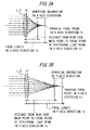
- FIG. 2A and FIG. 2B spherical aberration generated in a toric lens L2 is described with reference to FIG. 2A and FIG. 2B .
- the description is made by assuming that an optical axis of the toric lens L2 is taken on a Z axis, an XY plane orthogonal to the optical axis is set and an X axis and a Y axis are orthogonal to each other.
- the X axis and the Y axis may not be always orthogonal to each other, and may be configured such that the X axis extends in a first direction on the XY plane and the Y axis extends in a second direction which differs from the first direction.
- FIG. 2B illustrate states where light beams in the X axis direction and Y axis direction of the toric lens L2 converge respectively.
- a rear principal point of the toric lens L2 is H'
- a paraxial focal point in the X axis direction of the lens is Fx
- a focal length in the X axis direction of the lens is fx
- a distance from a rear principal point H' to a focal point of a peripheral light beam in the X axis direction of the lens is fx'.
- Fy, fy, fy' are respectively set also with respect to the Y axis direction of the lens.
- SAx, SAy indicate a distance of amounts of spherical aberration in the X axis direction of the lens and a distance of amounts of spherical aberration in the Y axis direction of the lens respectively.
- SAx, SAy in the toric lens L2 illustrated in FIG. 2A and FIG. 2B take negative values.
- Cylindrical refractivity Pc in a paraxial portion of the toric lens L2 and cylindrical refractivity Pc' in a peripheral portion of the toric lens L2 are expressed by the following formulas (8) and (9). Both cylindrical refractivities Pc, Pc' correspond to the difference between refractivity in the first direction and refractivity in the second direction. Further, Px, Px', Py and Py' respectively correspond to the first refractivity, second refractivity, third refractivity and fourth refractivity.
- a toric intraocular lens is manufactured by determining Pc and Pc' on a lens side such that cylindrical refractivities of a paraxial portion and a peripheral portion of an eye into which the intraocular lens is inserted cancel each other in the formulas (8) and (9).
- a toric intraocular lens is manufactured by individually determining SAx, SAy such that cylindrical refractivities of a paraxial portion and a peripheral portion of an eye into which the intraocular lens is inserted cancel each other in the formulas (5) and (7).
- the toric intraocular lens according to the present invention is not limited to the configuration where the difference in refractivity differs in two stages between a paraxial portion and a peripheral portion, and the toric intraocular lens may be configured such that the difference in refractivity continuously varies in a stepless manner from the center to the periphery of the lens.
- FIG. 3 illustrates Landolt ring images in so-called best focusing where a conventional toric lens and a toric lens according to this embodiment are applied to an astigmatic eye under a predetermined condition as intraocular lenses, Landolt ring images acquired when an image plane is moved away from the lens by 0.04 mm (+) in the simulation, and Landolt ring images when the image plane is made to approach the lens by 0.04 mm (-).
- the difference in Landolt ring image appears also when an image plane is moved so that the image is defocused.
- blurring having a rotation symmetrical shape is generated. That is, it is safe to say that astigmatism is substantially completely eliminated.
- blurring extends in a longitudinal direction (vertical direction on a paper on which FIG. 3 is drawn) (image plane: +0.04 mm) or extends in a lateral direction (left-and-right direction on the paper on which FIG.
- FIG. 4 illustrates the schematic configuration of a schematic eye used for the evaluation.
- an astigmatism cornea lens L3 is suitably rotatable about an optical axis. Accordingly, it is possible to make an astigmatism axis of the astigmatism cornea lens L3 and an astigmatism axis of a toric intraocular lens L4 agree with each other.
- the astigmatism cornea lens L3 is formed of a biconvex lens.
- the astigmatism cornea lens L3 may be a meniscus lens or a biconcave lens.
- the toric intraocular lens L4 is arranged in water by estimating the case where the toric intraocular lens L4 is disposed inside the eye.
- the schematic eye may be configured such that the toric intraocular lens L4 is arranged in air.
- Landolt rings described on a visual acuity chart having a length of 3 m are used.
- An index to be imaged is an optotype of 1.0 vision.
- a filter which allows light of 546 nm to pass therethrough is mounted on a halogen lump which forms a light source, and light which passes through the filter is irradiated to the visual acuity chart from a back side of the visual acuity chart.
- a camera 10 can move back-and-forth in a direction with respect to an optical axis of the toric intraocular lens L4 for focusing.
- the toric intraocular lens L4 is positioned inside an approximately rectangular parallelepiped casing 100 where both surfaces of the casing 100 are formed of planar glasses 101, 101.
- the inside of the casing 100 is filled with water, and a stop S is mounted on an astigmatism cornea lens L3 side of the toric intraocular lens L4.
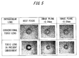
- FIG. 5 illustrates a result obtained by imaging Landolt rings which are indexes by a camera when the schematic eye illustrated in FIG. 4 is used.
- Landolt rings are clearly imaged in best focusing.
- images which are intentionally defocused by moving the camera 10 in an optical axis direction of the toric intraocular lens L4 blurring occurs in rotation symmetry. Accordingly, it is understood that astigmatism is favorably reduced.
- the conventional toric intraocular lens although Landolt rings are recognized in best focusing, images are remarkably degraded when the images are intentionally defocused. Accordingly, it is understood that astigmatism is not sufficiently reduced.
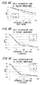
- FIGS. 6A to 6C illustrate a result obtained by measuring MTF (Modulation Transfer Function) of the toric intraocular lens of this embodiment using the configuration of the schematic eye illustrated in FIG. 5 .
- MTF Modulation Transfer Function
- spatial frequency indicative of a distance of stripes of a stripe pattern used as an object to be imaged is taken on an axis of abscissas
- a value of MTF of an image of the stripe pattern focused on a light receiving surface of a camera by the toric intraocular lens is illustrated on an axis of ordinates.
- a solid line indicates numerical values in a sagittal (radiation) direction of the toric intraocular lens (0 degree direction in this case), and a broken line indicates numerical values in a meridional (concentric) direction of the toric intraocular lens (90 degree direction in this case).
- MTF exhibits favorable values both in the 0 degree direction and in the 90 degree direction in best focusing. Further, even in defocusing, although values of MTF are lowered, MTF exhibits substantially the same change both in the 0 degree direction and in the 90 degree direction, and hence, it is understood that astigmatism is substantially not generated.
- FIGS. 7A to 7C illustrate a result obtained by measuring MTF of a conventional toric intraocular lens using the configuration of the schematic eye illustrated in FIG. 5 .
- MTF at spatial frequency of 100 lines/mm is 0.2 or more in best focusing, and hence, it is considered that the schematic eye can see the vision of 1.0.
- MTF exhibits low values compared to the toric intraocular lens of this embodiment.
- MTF exhibits different changes in the 0 degree direction and in the 90 degree direction even at the time of defocusing.
Landscapes
- Health & Medical Sciences (AREA)
- Ophthalmology & Optometry (AREA)
- Physics & Mathematics (AREA)
- General Health & Medical Sciences (AREA)
- Optics & Photonics (AREA)
- General Physics & Mathematics (AREA)
- Vascular Medicine (AREA)
- Heart & Thoracic Surgery (AREA)
- Biomedical Technology (AREA)
- Life Sciences & Earth Sciences (AREA)
- Animal Behavior & Ethology (AREA)
- Engineering & Computer Science (AREA)
- Public Health (AREA)
- Veterinary Medicine (AREA)
- Transplantation (AREA)
- Oral & Maxillofacial Surgery (AREA)
- Cardiology (AREA)
- Prostheses (AREA)
- Eyeglasses (AREA)
Abstract
Description
- The embodiments discussed herein pertain to a toric ophthalmic lens for correcting astigmatism.
- As examples of an ophthalmic lens for correcting astigmatism, eyeglasses, contact lenses, intraocular lenses and the like are named. These ophthalmic lenses have an optical surface referred to as a toric surface. It is noted that "toric surface" is a surface shape of a lens where radii of curvature of at least two meridians differ from each other as in the case of a side surface of a rugby ball or a doughnut. Accordingly, a lens having such a toric surface is referred to as a toric lens (circular annular lens).
- Due to a toric surface, the refractivity of a lens differs between directions orthogonal to each other which are set on the toric surface. Astigmatism can be corrected by making use of the difference in refractivity. In general, this difference in refractivity is referred to as cylindricalrefractivity. On a toric surface, a meridian in a direction where refractivity is large is referred to as a steep meridian, and a meridian in a direction where refractivity is small is referred to as a flat meridian. Further, an average value of refractivities on these two meridians is referred to as spherical equivalent power (or simply referred to as spherical power). Usually, in an ophthalmic lens for correcting astigmatism, as indexes indicative of optical performances, equivalent spherical power and cylindrical refractivity are used. Conventionally, there has been proposed a lens where, with respect to optical surfaces disposed in front of and behind the lens, a function of correcting astigmatic abnormality in vision is imparted to one optical surface, and a function of correcting spherical aberration is imparted to the other optical surface (patent literature 1).
- [PTL 1]
JP-A-2009-544059 - Recently, along with the development of measuring instruments in ophthalmology, cornea astigmatism in an eyeball can be accurately measured. For example, in an anterior eye part shape analyzer such as Pentacam (registered trademark) (made by OCULUS) or TMS-5 (made by TOMEY CORPORATION), a shape of cornea can be measured, and the distribution of refractive power from the center to the periphery of the cornea can be measured. The substantially same measurement can be also applied to an eye having astigmatism so that amounts of astigmatism ranging from the center to the periphery of a cornea can be also measured.
- However, in the conventional ophthalmic lens for correcting astigmatism, only the configuration where one optical surface of the lens is used as a toric surface is disclosed, and a control of cylindrical refractivity on the toric surface is not taken into consideration. Accordingly, even when amounts of astigmatism ranging from the center to the periphery of a cornea can be grasped by the above-mentioned measurement, astigmatism components cannot be properly removed over the whole cornea in the conventional ophthalmic lens for correcting astigmatism whereby the proper improvement of visual functions is limited.
- The technique of this disclosure is made in view of the above-mentioned circumstances, and it is an object of this disclosure to realize a toric ophthalmic lens capable of more properly correcting amounts of astigmatism of a cornea.
- According to an embodiment, it is provided A toric ophthalmic lens wherein refractivity of the lens differs between a first direction on a plane perpendicular to an optical axis of the lens and a second direction which differs from the first direction on the plane, wherein refractivity difference which is the difference between the refractivity in the first direction and the refractivity in the second direction varies depending on a position of the lens in a radial direction. Further, according to the toric ophthalmic lens of the present embodiment, the refractivity difference varies so as to attenuate a variation in refractivity with respect to a radial direction or a circumferential direction in a cornea of an eyeball in which the lens is mounted. With such a configuration, by controlling a amounts of astigmatism in the center portion of the lens and a amounts of astigmatism in the peripheral portion of the lens respectively, it is possible to provide a toric ophthalmic lens which can more properly perform correction of astigmatism compared to a prior art.
- In addition, the toric ophthalmic lens according to the present disclosure is the toric ophthalmic lens wherein with respect to first refractivity in a paraxial portion of the lens in the first direction, second refractivity in a peripheral portion of the lens in the first direction, third refractivity in the paraxial portion of the lens in the second direction, and fourth refractivity in the peripheral portion of the lens in the second direction, the difference between the first refractivity and the third refractivity is refractivity difference in the paraxial portion of the lens and the difference between the second refractivity and the fourth refractivity is refractivity difference in the peripheral portion of the lens, and the refractivity difference in the paraxial portion of the lens and the refractivity difference in the peripheral portion of the lens are controlled to be different from each other. Alternatively, there is provided the toric ophthalmic lens, wherein amounts of first spherical aberration in the first direction and amounts of second spherical aberration in the second direction are controlled individually.
- According to the technique of this disclosure, it is possible to realize a toric ophthalmic lens capable of more properly correcting amounts of astigmatism of an eyeball.
-
-
FIG. 1 is a schematic diagram illustrating spherical aberration of a lens; -
FIG. 2A and FIG. 2B are schematic diagrams illustrating spherical aberration of a toric lens; -
FIG. 3 is a table illustrating one example of a simulation result of a toric intraocular lens according to this embodiment and a conventional toric intraocular lens; -
FIG. 4 is a diagram illustrating the schematic constitution of a schematic eye prepared for evaluating the toric intraocular lens; -
FIG. 5 is a table illustrating one example of the evaluation result of the schematic eye illustrated inFIG. 4 ; -
FIGS. 6A to 6C are graphs illustrating one example of a measurement result of an MTF of the toric intraocular lens according to this embodiment; and -
FIGS. 7A to 7C are graphs illustrating one example of a measurement result of an MTF of a conventional toric intraocular lens. - Hereinafter, an embodiment of the present invention is described with reference to drawings. Although a toric intraocular lens will be described in the description made hereinafter, the present invention is not limited to the intraocular lens and is also applicable to various ophthalmic lenses including contact lenses.
- Firstly, spherical aberration which is one of Seidel' s five aberrations is described with reference to
FIG. 1 . When spherical aberration occurs, power difference is generated between a center portion (paraxial portion) and a peripheral portion of a rotation-symmetry-type lens. Spherical aberration is a phenomenon where a light which passes through the center portion of the lens and a light which passes through the peripheral portion of the lens do not converge on the same focal point. - As illustrated in
FIG. 1 , assuming a rear principal point of a lens L1 as H', a paraxial focal point as F, a focal length as f, and a distance from the rear principal point H' to a focal point of a peripheral light beam (a light which passes through a peripheral portion of the lens) as f', paraxial refractivity of the lens L1 P is expressed by the following formula (1) using the focal length f. Although the description is made with respect to the case where air is present in front of and behind the lens and a refractive index is set to 1, the present invention is not limited to such a case.
- In this embodiment, the case where spherical aberration is generated means the case where the position of a focal point F' of a peripheral light beam and the position of the paraxial focal point F differ from each other, and refractivity P' of a peripheral portion of the lens L1 is expressed by the following formula (2) using the distance f'.

- In
FIG. 1 , the focal point F' of the peripheral light beam is closer to the rear principal point H' than the paraxial focal point F is and hence, the following formula (3) is established. That is, when spherical aberration is generated in the lens L1, difference is generated in refractivity between the center portion and the peripheral portion of the lens L1.
- Next, spherical aberration generated in a toric lens L2 is described with reference to
FIG. 2A and FIG. 2B . For the sake of convenience of description, the description is made by assuming that an optical axis of the toric lens L2 is taken on a Z axis, an XY plane orthogonal to the optical axis is set and an X axis and a Y axis are orthogonal to each other. However, the X axis and the Y axis may not be always orthogonal to each other, and may be configured such that the X axis extends in a first direction on the XY plane and the Y axis extends in a second direction which differs from the first direction.FIG. 2A and FIG. 2B illustrate states where light beams in the X axis direction and Y axis direction of the toric lens L2 converge respectively. As illustrated inFIG. 2A , it is assumed that a rear principal point of the toric lens L2 is H' , a paraxial focal point in the X axis direction of the lens is Fx, a focal length in the X axis direction of the lens is fx, and a distance from a rear principal point H' to a focal point of a peripheral light beam in the X axis direction of the lens is fx'. In the same manner, as illustrated inFIG. 2B , Fy, fy, fy' are respectively set also with respect to the Y axis direction of the lens. - In this case, as described with reference to
FIG. 1 , the following formulas (4) to (7) are established.


- Here, SAx, SAy indicate a distance of amounts of spherical aberration in the X axis direction of the lens and a distance of amounts of spherical aberration in the Y axis direction of the lens respectively. For example, SAx, SAy in the toric lens L2 illustrated in
FIG. 2A and FIG. 2B take negative values. - Cylindrical refractivity Pc in a paraxial portion of the toric lens L2 and cylindrical refractivity Pc' in a peripheral portion of the toric lens L2 are expressed by the following formulas (8) and (9). Both cylindrical refractivities Pc, Pc' correspond to the difference between refractivity in the first direction and refractivity in the second direction. Further, Px, Px', Py and Py' respectively correspond to the first refractivity, second refractivity, third refractivity and fourth refractivity.


- In this embodiment, for the purpose of alleviating astigmatism of a cornea in the radial direction or in the circumferential direction by measuring a shape of an eyeball, a toric intraocular lens is manufactured by determining Pc and Pc' on a lens side such that cylindrical refractivities of a paraxial portion and a peripheral portion of an eye into which the intraocular lens is inserted cancel each other in the formulas (8) and (9). Alternatively, a toric intraocular lens is manufactured by individually determining SAx, SAy such that cylindrical refractivities of a paraxial portion and a peripheral portion of an eye into which the intraocular lens is inserted cancel each other in the formulas (5) and (7). Accordingly, not only amounts of astigmatism in the center portion of the lens but also amounts of astigmatism in the peripheral portion of the lens can be controlled, and hence, it is possible to provide a lens having a more favorable astigmatism correcting function compared to a conventional toric intraocular lens. The toric intraocular lens according to the present invention is not limited to the configuration where the difference in refractivity differs in two stages between a paraxial portion and a peripheral portion, and the toric intraocular lens may be configured such that the difference in refractivity continuously varies in a stepless manner from the center to the periphery of the lens.
- Next, in this embodiment, with reference to
FIG. 3 , the description is made with respect to a simulation result on Landolt ring images acquired by a toric intraocular lens when the toric intraocular lens is designed using the formulas (8) and (9).FIG. 3 illustrates Landolt ring images in so-called best focusing where a conventional toric lens and a toric lens according to this embodiment are applied to an astigmatic eye under a predetermined condition as intraocular lenses, Landolt ring images acquired when an image plane is moved away from the lens by 0.04 mm (+) in the simulation, and Landolt ring images when the image plane is made to approach the lens by 0.04 mm (-). - As can be understood from the Landolt rings in best focusing illustrated in
FIG. 3 , in the toric intraocular lens according to this embodiment, astigmatism is favorably reduced so that a clear Landolt ring image is acquired. On the other hand, in the conventional toric intraocular lens, although a Landolt ring image is confirmed to an extent that the image is recognizable, so-called blurring is generated around the Landolt ring. - Further, the difference in Landolt ring image appears also when an image plane is moved so that the image is defocused. As illustrated in
FIG. 3 , in the toric intraocular lens according to this embodiment, even when an image plane is displaced from the position for best focusing, blurring having a rotation symmetrical shape is generated. That is, it is safe to say that astigmatism is substantially completely eliminated. On the other hand, in the conventional toric intraocular lens, blurring extends in a longitudinal direction (vertical direction on a paper on whichFIG. 3 is drawn) (image plane: +0.04 mm) or extends in a lateral direction (left-and-right direction on the paper on whichFIG. 3 is drawn) (image plane: -0.04 mm) and, hence, it is understood that astigmatism is not completely eliminated. From the above, it is safe to say that the toric intraocular lens according to this embodiment can acquire more effective astigmatism correction effect compared to the prior art. - Next, the description is made on an evaluation result with respect to the case where an astigmatism cornea lens which differs in amounts of astigmatism between a center portion and a peripheral portion of the lens is manufactured.
FIG. 4 illustrates the schematic configuration of a schematic eye used for the evaluation. In the schematic eye illustrated inFIG. 4 , an astigmatism cornea lens L3 is suitably rotatable about an optical axis. Accordingly, it is possible to make an astigmatism axis of the astigmatism cornea lens L3 and an astigmatism axis of a toric intraocular lens L4 agree with each other. InFIG. 4 , the astigmatism cornea lens L3 is formed of a biconvex lens. However, the astigmatism cornea lens L3 may be a meniscus lens or a biconcave lens. - In the schematic eye illustrated in
FIG. 4 , the toric intraocular lens L4 is arranged in water by estimating the case where the toric intraocular lens L4 is disposed inside the eye. However, the schematic eye may be configured such that the toric intraocular lens L4 is arranged in air. As indices to be observed with respect to the schematic eye illustrated inFIG. 4 , Landolt rings described on a visual acuity chart having a length of 3 m are used. An index to be imaged is an optotype of 1.0 vision. A filter which allows light of 546 nm to pass therethrough is mounted on a halogen lump which forms a light source, and light which passes through the filter is irradiated to the visual acuity chart from a back side of the visual acuity chart. Acamera 10 can move back-and-forth in a direction with respect to an optical axis of the toric intraocular lens L4 for focusing. As illustrated inFIG. 4 , the toric intraocular lens L4 is positioned inside an approximatelyrectangular parallelepiped casing 100 where both surfaces of thecasing 100 are formed ofplanar glasses casing 100 is filled with water, and a stop S is mounted on an astigmatism cornea lens L3 side of the toric intraocular lens L4. -
FIG. 5 illustrates a result obtained by imaging Landolt rings which are indexes by a camera when the schematic eye illustrated inFIG. 4 is used. As illustrated inFIG. 5 , in the same manner as the simulation result illustrated inFIG. 3 , in the toric intraocular lens L4 of this embodiment, Landolt rings are clearly imaged in best focusing. Further, also with respect to images which are intentionally defocused by moving thecamera 10 in an optical axis direction of the toric intraocular lens L4, blurring occurs in rotation symmetry. Accordingly, it is understood that astigmatism is favorably reduced. On the other hand, in the conventional toric intraocular lens, although Landolt rings are recognized in best focusing, images are remarkably degraded when the images are intentionally defocused. Accordingly, it is understood that astigmatism is not sufficiently reduced. -
FIGS. 6A to 6C illustrate a result obtained by measuring MTF (Modulation Transfer Function) of the toric intraocular lens of this embodiment using the configuration of the schematic eye illustrated inFIG. 5 . In the drawings, spatial frequency indicative of a distance of stripes of a stripe pattern used as an object to be imaged is taken on an axis of abscissas, and a value of MTF of an image of the stripe pattern focused on a light receiving surface of a camera by the toric intraocular lens is illustrated on an axis of ordinates. A solid line indicates numerical values in a sagittal (radiation) direction of the toric intraocular lens (0 degree direction in this case), and a broken line indicates numerical values in a meridional (concentric) direction of the toric intraocular lens (90 degree direction in this case). As illustrated inFIGS. 6A to 6C , in the case of the schematic eye into which the toric intraocular lens of this embodiment is inserted, it is understood that MTF exhibits favorable values both in the 0 degree direction and in the 90 degree direction in best focusing. Further, even in defocusing, although values of MTF are lowered, MTF exhibits substantially the same change both in the 0 degree direction and in the 90 degree direction, and hence, it is understood that astigmatism is substantially not generated. - Next,
FIGS. 7A to 7C illustrate a result obtained by measuring MTF of a conventional toric intraocular lens using the configuration of the schematic eye illustrated inFIG. 5 . As illustrated inFIGS. 7A to 7C , in the conventional toric intraocular lens, MTF at spatial frequency of 100 lines/mm is 0.2 or more in best focusing, and hence, it is considered that the schematic eye can see the vision of 1.0. However, as can be understood fromFIGS. 6A to 6C , MTF exhibits low values compared to the toric intraocular lens of this embodiment. Further, as illustrated inFIGS. 7A to 7C , in the conventional toric intraocular lens, MTF exhibits different changes in the 0 degree direction and in the 90 degree direction even at the time of defocusing. Accordingly, it is safe to say that astigmatism still remains in the conventional toric intraocular lens. As has been set forth above, with the use of the toric intraocular lens which is designed in the above-mentioned manner by taking into account not only amounts of astigmatism at a center portion of the lens but also amounts of astigmatism at a peripheral portion of the lens in accordance with this embodiment, the correction of astigmatism can be performed more favorably compared to the prior art. -
- L1
- lens
- L2
- toric lens
- L3
- astigmatism cornea lens
- L4
- toric intraocular lens
Claims (4)
- A toric ophthalmic lens wherein refractivity of the lens differs between a first direction on a plane perpendicular to an optical axis of the lens and a second direction which differs from the first direction on the plane, characterized in that
refractivity difference which is the difference between the refractivity in the first direction and the refractivity in the second direction varies depending on a position of the lens in a radial direction. - The toric ophthalmic lens according to claim 1, wherein the refractivity difference varies so as to attenuate a variation in refractivity with respect to a radial direction or a circumferential direction in a cornea of an eyeball in which the lens is mounted.
- The toric ophthalmic lens according to claim 1 or claim 2, wherein with respect to first refractivity in a paraxial portion of the lens in the first direction, second refractivity in a peripheral portion of the lens in the first direction, third refractivity in the paraxial portion of the lens in the second direction, and fourth refractivity in the peripheral portion of the lens in the second direction, the difference between the first refractivity and the third refractivity is refractivity difference in the paraxial portion of the lens and the difference between the second refractivity and the fourth refractivity is refractivity difference in the peripheral portion of the lens, and the refractivity difference in the paraxial portion of the lens and the refractivity difference in the peripheral portion of the lens are controlled to be different from each other.
- The toric ophthalmic lens according to any one of claims 1 to 3, wherein amounts of first spherical aberration in the first direction and amounts of second spherical aberration in the second direction are controlled individually.
Applications Claiming Priority (2)
| Application Number | Priority Date | Filing Date | Title |
|---|---|---|---|
| JP2014006171 | 2014-01-16 | ||
| PCT/JP2015/051115 WO2015108156A1 (en) | 2014-01-16 | 2015-01-16 | Toric intraocular lens |
Publications (2)
| Publication Number | Publication Date |
|---|---|
| EP3096179A1 true EP3096179A1 (en) | 2016-11-23 |
| EP3096179A4 EP3096179A4 (en) | 2017-09-13 |
Family
ID=53543039
Family Applications (1)
| Application Number | Title | Priority Date | Filing Date |
|---|---|---|---|
| EP15737580.9A Withdrawn EP3096179A4 (en) | 2014-01-16 | 2015-01-16 | Toric intraocular lens |
Country Status (6)
| Country | Link |
|---|---|
| US (1) | US10646328B2 (en) |
| EP (1) | EP3096179A4 (en) |
| JP (2) | JP6854079B2 (en) |
| CN (1) | CN105980915A (en) |
| SG (2) | SG11201605735SA (en) |
| WO (1) | WO2015108156A1 (en) |
Families Citing this family (7)
| Publication number | Priority date | Publication date | Assignee | Title |
|---|---|---|---|---|
| US10004593B2 (en) | 2009-08-13 | 2018-06-26 | Acufocus, Inc. | Intraocular lens with elastic mask |
| US9492272B2 (en) | 2009-08-13 | 2016-11-15 | Acufocus, Inc. | Masked intraocular implants and lenses |
| WO2013082545A1 (en) | 2011-12-02 | 2013-06-06 | Acufocus, Inc. | Ocular mask having selective spectral transmission |
| ES2972581T3 (en) | 2015-10-05 | 2024-06-13 | Acufocus Inc | Intraocular lens molding methods |
| JP7055747B2 (en) | 2015-11-24 | 2022-04-18 | アキュフォーカス・インコーポレーテッド | Toric small aperture intraocular lens with extended depth of focus |
| WO2019217471A1 (en) | 2018-05-09 | 2019-11-14 | Acufocus, Inc. | Intraocular implant with removable optic |
| CN119744138A (en) * | 2022-09-13 | 2025-04-01 | 爱尔康公司 | Toric intraocular lens alignment guidance |
Family Cites Families (22)
| Publication number | Priority date | Publication date | Assignee | Title |
|---|---|---|---|---|
| JP4023902B2 (en) * | 1998-04-10 | 2007-12-19 | 株式会社メニコン | Toric multifocal lens |
| US6183084B1 (en) * | 1998-07-30 | 2001-02-06 | Johnson & Johnson Vision Care, Inc. | Progressive addition lenses |
| JP4510177B2 (en) * | 1999-07-08 | 2010-07-21 | 東海光学株式会社 | Progressive focus lens for spectacles, manufacturing method thereof, and spectacles using the progressive focus lens for spectacles |
| JP4361254B2 (en) | 2002-10-08 | 2009-11-11 | 株式会社ニコン・エシロール | Spectacle lens design method, spectacle lens manufacturing method, and computer program |
| JP4195663B2 (en) * | 2004-01-13 | 2008-12-10 | 東海光学株式会社 | Manufacturing method of lens for correcting astigmatism |
| AR062067A1 (en) | 2006-07-17 | 2008-10-15 | Novartis Ag | TORICAS CONTACT LENSES WITH CONTROLLED OPTICAL POWER PROFILE |
| US8529559B2 (en) | 2007-10-29 | 2013-09-10 | Junzhong Liang | Methods and devices for refractive treatments of presbyopia |
| US8439498B2 (en) * | 2008-02-21 | 2013-05-14 | Abbott Medical Optics Inc. | Toric intraocular lens with modified power characteristics |
| WO2009124040A1 (en) * | 2008-04-01 | 2009-10-08 | Scientific Optics, Inc. | Universal contact lens posterior surface construction |
| US20100079723A1 (en) * | 2008-10-01 | 2010-04-01 | Kingston Amanda C | Toric Ophthalimc Lenses Having Selected Spherical Aberration Characteristics |
| US9277863B2 (en) | 2008-12-01 | 2016-03-08 | Perfect Vision Technology (Hk) Ltd. | Methods and systems for automated measurement of the eyes and delivering of sunglasses and eyeglasses |
| JP6076599B2 (en) | 2008-12-01 | 2017-02-08 | パーフェクト・ビジョン・テクノロジー・(ホンコン)・リミテッドPerfect Vision Technology (Hk) Ltd. | Method and apparatus for refractive correction of the eye |
| US9649032B2 (en) | 2008-12-01 | 2017-05-16 | Perfect Vision Technology (Hk) Ltd. | Systems and methods for remote measurement of the eyes and delivering of sunglasses and eyeglasses |
| US8087778B2 (en) * | 2009-02-13 | 2012-01-03 | Adlens Beacon, Inc. | Variable focus liquid filled lens mechanism |
| US20100208194A1 (en) | 2009-02-13 | 2010-08-19 | Amitava Gupta | Variable focus liquid filled lens apparatus |
| US20100315589A1 (en) * | 2009-06-16 | 2010-12-16 | Valdemar Portney | Toric ophthalmic lens |
| JP5657266B2 (en) | 2010-04-14 | 2015-01-21 | 株式会社メニコン | Contact lenses for correcting irregular astigmatism |
| DE102010018436B4 (en) * | 2010-04-27 | 2017-02-09 | Carl Zeiss Meditec Ag | Multifocal eye lens |
| AU2012249773A1 (en) * | 2011-04-28 | 2013-11-07 | Nexisvision, Inc. | Eye covering and refractive correction methods and apparatus having improved tear flow, comfort, and/or applicability |
| JP5747279B2 (en) | 2011-04-28 | 2015-07-15 | 東海光学株式会社 | Design method for vision correction lens |
| US9046698B2 (en) * | 2012-02-28 | 2015-06-02 | Johnson & Johnson Vision Care, Inc. | Multi-axis lens design for astigmatism |
| TWI588560B (en) | 2012-04-05 | 2017-06-21 | 布萊恩荷登視覺協會 | Lens, device, method and system for refractive error |
-
2015
- 2015-01-16 SG SG11201605735SA patent/SG11201605735SA/en unknown
- 2015-01-16 JP JP2015557895A patent/JP6854079B2/en active Active
- 2015-01-16 EP EP15737580.9A patent/EP3096179A4/en not_active Withdrawn
- 2015-01-16 SG SG10201805879UA patent/SG10201805879UA/en unknown
- 2015-01-16 US US15/111,158 patent/US10646328B2/en active Active
- 2015-01-16 WO PCT/JP2015/051115 patent/WO2015108156A1/en not_active Ceased
- 2015-01-16 CN CN201580004731.6A patent/CN105980915A/en active Pending
-
2020
- 2020-12-14 JP JP2020206918A patent/JP2021039387A/en active Pending
Also Published As
| Publication number | Publication date |
|---|---|
| CN105980915A (en) | 2016-09-28 |
| SG11201605735SA (en) | 2016-09-29 |
| JPWO2015108156A1 (en) | 2017-03-23 |
| JP2021039387A (en) | 2021-03-11 |
| US10646328B2 (en) | 2020-05-12 |
| JP6854079B2 (en) | 2021-04-07 |
| US20160331522A1 (en) | 2016-11-17 |
| SG10201805879UA (en) | 2018-08-30 |
| WO2015108156A1 (en) | 2015-07-23 |
| EP3096179A4 (en) | 2017-09-13 |
Similar Documents
| Publication | Publication Date | Title |
|---|---|---|
| US10646328B2 (en) | Toric ophthalmic lens | |
| US20220244568A1 (en) | Ophthalmic lens | |
| JP4856277B2 (en) | Apparatus and method for determining a required correction value for abnormal eyesight | |
| US10799338B2 (en) | Wide depth of focus vortex intraocular lenses and associated methods | |
| US10168549B2 (en) | Optical visual aid with additional astigmatism | |
| CN103300813B (en) | Subjective optometry instrument and optometry method | |
| KR20110104963A (en) | Correction of peripheral defocus of eyes and control of occurrence of refractive error | |
| Calatayud et al. | Imaging quality of multifocal intraocular lenses: automated assessment setup | |
| JP6708955B2 (en) | Eyeglass prescription auxiliary device and eyeglass prescription auxiliary program | |
| KR101859261B1 (en) | Method and system for determining an eyeglass prescription | |
| HK1229009A1 (en) | Toric intraocular lens | |
| Shuker et al. | Electro-Optic Designing and Construction to test the Tilting and the Decentering | |
| JP6693240B2 (en) | Eyeglass prescription auxiliary device | |
| Zhai et al. | Construction of special eye models for investigation of chromatic and higher-order aberrations of eyes | |
| HK1236627A1 (en) | Ophthalmic lens and method for designing ophthalmic lens | |
| KR101538129B1 (en) | Standard lens for eye refractometer | |
| Blaker | Quality control of intraocular lens optics | |
| Choi et al. | Lens design of the eyepiece combined with the accommodation-dependent navarro eye at an on-axis point | |
| Almaguer et al. | Highly aberrated phase elements for presbyopia and astigmatism correction | |
| HK1236627B (en) | Ophthalmic lens and method for designing ophthalmic lens |
Legal Events
| Date | Code | Title | Description |
|---|---|---|---|
| PUAI | Public reference made under article 153(3) epc to a published international application that has entered the european phase |
Free format text: ORIGINAL CODE: 0009012 |
|
| 17P | Request for examination filed |
Effective date: 20160711 |
|
| AK | Designated contracting states |
Kind code of ref document: A1 Designated state(s): AL AT BE BG CH CY CZ DE DK EE ES FI FR GB GR HR HU IE IS IT LI LT LU LV MC MK MT NL NO PL PT RO RS SE SI SK SM TR |
|
| AX | Request for extension of the european patent |
Extension state: BA ME |
|
| DAX | Request for extension of the european patent (deleted) | ||
| A4 | Supplementary search report drawn up and despatched |
Effective date: 20170811 |
|
| RIC1 | Information provided on ipc code assigned before grant |
Ipc: G02C 7/02 20060101ALI20170807BHEP Ipc: G02C 7/04 20060101AFI20170807BHEP Ipc: A61F 2/16 20060101ALI20170807BHEP |
|
| STAA | Information on the status of an ep patent application or granted ep patent |
Free format text: STATUS: EXAMINATION IS IN PROGRESS |
|
| 17Q | First examination report despatched |
Effective date: 20210423 |
|
| STAA | Information on the status of an ep patent application or granted ep patent |
Free format text: STATUS: THE APPLICATION IS DEEMED TO BE WITHDRAWN |
|
| 18D | Application deemed to be withdrawn |
Effective date: 20250312 |