EP3096164A1 - Optical coupling device and optical coupling unit - Google Patents
Optical coupling device and optical coupling unit Download PDFInfo
- Publication number
- EP3096164A1 EP3096164A1 EP14878417.6A EP14878417A EP3096164A1 EP 3096164 A1 EP3096164 A1 EP 3096164A1 EP 14878417 A EP14878417 A EP 14878417A EP 3096164 A1 EP3096164 A1 EP 3096164A1
- Authority
- EP
- European Patent Office
- Prior art keywords
- optical
- reflecting prism
- optical fibre
- angle
- path
- Prior art date
- Legal status (The legal status is an assumption and is not a legal conclusion. Google has not performed a legal analysis and makes no representation as to the accuracy of the status listed.)
- Granted
Links
Images



Classifications
-
- G—PHYSICS
- G02—OPTICS
- G02B—OPTICAL ELEMENTS, SYSTEMS OR APPARATUS
- G02B6/00—Light guides; Structural details of arrangements comprising light guides and other optical elements, e.g. couplings
- G02B6/24—Coupling light guides
- G02B6/42—Coupling light guides with opto-electronic elements
- G02B6/4201—Packages, e.g. shape, construction, internal or external details
- G02B6/4204—Packages, e.g. shape, construction, internal or external details the coupling comprising intermediate optical elements, e.g. lenses, holograms
- G02B6/4214—Packages, e.g. shape, construction, internal or external details the coupling comprising intermediate optical elements, e.g. lenses, holograms the intermediate optical element having redirecting reflective means, e.g. mirrors, prisms for deflecting the radiation from horizontal to down- or upward direction toward a device
-
- G—PHYSICS
- G02—OPTICS
- G02B—OPTICAL ELEMENTS, SYSTEMS OR APPARATUS
- G02B6/00—Light guides; Structural details of arrangements comprising light guides and other optical elements, e.g. couplings
- G02B6/24—Coupling light guides
- G02B6/26—Optical coupling means
- G02B6/34—Optical coupling means utilising prism or grating
-
- G—PHYSICS
- G02—OPTICS
- G02B—OPTICAL ELEMENTS, SYSTEMS OR APPARATUS
- G02B6/00—Light guides; Structural details of arrangements comprising light guides and other optical elements, e.g. couplings
- G02B6/24—Coupling light guides
- G02B6/42—Coupling light guides with opto-electronic elements
- G02B6/4201—Packages, e.g. shape, construction, internal or external details
- G02B6/4219—Mechanical fixtures for holding or positioning the elements relative to each other in the couplings; Alignment methods for the elements, e.g. measuring or observing methods especially used therefor
- G02B6/4228—Passive alignment, i.e. without a detection of the degree of coupling or the position of the elements
- G02B6/423—Passive alignment, i.e. without a detection of the degree of coupling or the position of the elements using guiding surfaces for the alignment
-
- G—PHYSICS
- G02—OPTICS
- G02B—OPTICAL ELEMENTS, SYSTEMS OR APPARATUS
- G02B6/00—Light guides; Structural details of arrangements comprising light guides and other optical elements, e.g. couplings
- G02B6/24—Coupling light guides
- G02B6/42—Coupling light guides with opto-electronic elements
- G02B6/4201—Packages, e.g. shape, construction, internal or external details
- G02B6/4219—Mechanical fixtures for holding or positioning the elements relative to each other in the couplings; Alignment methods for the elements, e.g. measuring or observing methods especially used therefor
- G02B6/4236—Fixing or mounting methods of the aligned elements
- G02B6/4244—Mounting of the optical elements
-
- G—PHYSICS
- G02—OPTICS
- G02B—OPTICAL ELEMENTS, SYSTEMS OR APPARATUS
- G02B6/00—Light guides; Structural details of arrangements comprising light guides and other optical elements, e.g. couplings
- G02B6/24—Coupling light guides
- G02B6/42—Coupling light guides with opto-electronic elements
- G02B6/4201—Packages, e.g. shape, construction, internal or external details
- G02B6/4249—Packages, e.g. shape, construction, internal or external details comprising arrays of active devices and fibres
- G02B6/425—Optical features
-
- H—ELECTRICITY
- H04—ELECTRIC COMMUNICATION TECHNIQUE
- H04B—TRANSMISSION
- H04B10/00—Transmission systems employing electromagnetic waves other than radio-waves, e.g. infrared, visible or ultraviolet light, or employing corpuscular radiation, e.g. quantum communication
- H04B10/25—Arrangements specific to fibre transmission
Definitions
- the present disclosure relates to the field of optical communications, and in particular to an optical coupling device and an optical coupling unit.
- An optical interconnection method based on an optical waveguide has the advantages of high bandwidth, high density, high transmission speed, low transmission power consumption, low loss, basic avoidance of crosstalk, electromagnetic compatibility and the like.
- replacement of an electric printed backboard with an optical printed backboard based on an optical waveguide has become a general trend of high-speed and broadband interconnection development and is a core technology for solving the problem about interconnection bandwidths of the broadband communication networks, the super computers and the big data centres in the future.
- optical path transfer links such as an optical path transfer between an optical source and an optical waveguide, an optical path transfer between an optical fibre and an optical waveguide and an optical path transfer between two optical waveguides.
- optical coupling efficiency is a most concerned factor as the magnitude of coupling efficiency will directly affect the insertion loss of an optical interconnection link, thereby causing shortening of an interconnection distance.
- an optical coupling related device plays an important role in the interconnection optical waveguide system, and is an important link for determining the performance of the interconnection system.
- the embodiments of the present disclosure provide an optical coupling device and an optical coupling unit.
- An optical coupling device including: a right-angle reflecting prism and an mobile optical fibre connector, wherein a reflecting surface of the right-angle reflecting prism is provided with a curve reflecting surface, the curve reflecting surface being used for gathering and reflecting rays propagated by an optical fibre; and the mobile optical fibre connector is fixed to the right-angle reflecting prism, to make the rays propagated by the optical fibre being incident on the curve reflecting surface of the right-angle reflecting prism.
- the mobile optical fibre connector is provided with an optical fibre coupling tube, and a central position and an interval of the curve reflecting surface are identical to a central position and an interval of the optical fibre coupling tube.
- a curvature of the curve reflecting surface is designed according to a value of an aperture parameter of the optical fibre coupling tube, to make rays incident on the curve reflecting surface from the optical fibre at a maximum incident angle being gathered by the curve reflecting surface and then reflected in parallel.
- a type of the right-angle reflecting prism of the optical coupling device is a single-path reflecting prism, a double-path reflecting prism, a single-row multi-path reflecting prism or a double-row multi-path reflecting prism in sequence
- a type of the mobile optical fibre connector used for fixing the right-angle reflecting prism is a single-row mobile optical fibre connector, a double-path mobile optical fibre connector, a single-row multi-path mobile optical fibre connector or a double-row multi-path mobile optical fibre connector in sequence.
- a diameter and position of a locating guide pin hole of the right-angle reflecting prism correspond to a diameter and position of a locating guide pin hole of the mobile optical fibre connector.
- the mobile optical fibre connector is connected to the right-angle reflecting prism via a locating guide pin, and the locating guide pin is connected to the locating guide pin hole in the right-angle reflecting prism and the locating guide pin hole in the mobile optical fibre connector respectively; and the right-angle reflecting prism is fixed to a surface of the mobile optical fibre connector via ultraviolet glue, and the ultraviolet glue is applied to a joint between the locating guide pin and the right-angle reflecting prism, and a joint between the locating guide pin and the mobile optical fibre connector; or applied to an area, connected to the mobile optical fibre connector, at an edge of the right-angle reflecting prism.
- An optical coupling unit is provided in another embodiment of the present disclosure, including an optical waveguide and the optical coupling device as claimed in any one of claims 1 to 6, wherein the optical coupling device is provided being vertically inserted into the optical waveguide, to make rays reflected by the curve reflecting surface on the right-angle reflecting prism in the optical coupling device being incident in the optical waveguide and propagated.
- the optical coupling device being vertically inserted into the optical waveguide includes: a groove being provided at a position above a planar optical waveguide substrate in the optical waveguide, the right-angle reflecting prism in the optical coupling device being vertically inserted into the groove, and a size of the groove being greater than or equal to a size of the right-angle reflecting prism.
- a type of the right-angle reflecting prism in the optical coupling device is a single-path reflecting prism, a double-path reflecting prism, a single-row multi-path reflecting prism or a double-row multi-path reflecting prism in sequence
- a type of the optical waveguide is a single-path optical waveguide, a double-path optical waveguide, a single-row multi-path optical waveguide or a double-row multi-path optical waveguide in sequence.
- a curvature of the curve reflecting surface of the right-angle reflecting prism in the optical coupling device is designed according to a value of an aperture parameter of an optical fibre coupling tube and a value of an aperture parameter of the optical waveguide, to make rays incident on the curve reflecting surface from the optical fibre at a maximum incident angle being gathered by the curve reflecting surface, and an angle of the reflected ray being smaller than an angle corresponding to an value of an aperture of the optical waveguide.
- a reflecting surface of a right-angle reflecting prism is provided with a curve reflecting surface
- a mobile optical fibre connector in the optical coupling device is fixed to the right-angle reflecting prism, so that the rays propagated by the optical fibre are incident on the curve reflecting surface, thereby gathering and reflecting the rays propagated by the optical fibre.
- the loss of optical propagation can be reduced, and the optical coupling efficiency is improved; and moreover, the optical coupling device and the optical coupling unit provided by the embodiments of the present disclosure have simple structures, and manufacturing methods are simple and easy to operate.
- an optical coupling device including a mobile optical fibre connector and a right-angle reflecting prism is provided.
- a reflecting surface of the right-angle reflecting prism is provided with a curve reflecting surface, and the mobile optical fibre connector is fixed to the right-angle reflecting prism, so that rays propagated by an optical fibre are incident on the curve reflecting surface, thereby gathering and reflecting the rays propagated by the optical fibre.
- the loss of optical propagation can be reduced, and the optical coupling efficiency can be improved.
- Fig. 1 is a cross-section view of a right-angle reflecting prism.
- two right-angle sides AB and AC represent two side surfaces, vertical to each other, on the right-angle reflecting prism
- BC represents a reflecting surface on the right-angle reflecting prism.
- Fig. 2 is a section view of an optical coupling device according to an embodiment of the present disclosure.
- the optical coupling device includes a mobile optical fibre connector 21 and a right-angle reflecting prism 23.
- a reflecting surface of the right-angle reflecting prism 23 is provided with a curve reflecting surface 24, and the curve reflecting surface 24 is configured to gather and reflect the rays incident on the curve reflecting surface 24;
- the mobile optical fibre connector 21 is fixed to the right-angle reflecting prism 23; and the mobile optical fibre connector 21 includes an optical fibre coupling tube 22, and the optical fibre coupling tube 22 is configured to fix and align an optical fibre, so that the rays propagated by the optical fibre are incident on the curve reflecting surface 24 of the right-angle reflecting prism 23.
- the curve reflecting surface 24 is coated with a high-reflectivity optical thin film
- the optical thin film on the curve reflecting surface 24 may be a gold thin film, a silver thin film or other metal thin films, or may be other medium thin films
- the film-coated curve reflecting surface 24 can achieve higher reflectivity, thereby totally reflecting incident rays
- the optical fibre is fixed inside the optical fibre coupling tube 22 in the mobile optical fibre connector 21, the incident rays transmitted by the optical fibre are incident on the curve reflecting surface 24 of the right-angle reflecting prism, and then the incident rays are reflected by the curve reflecting surface 24 coated with the high-reflectivity optical thin film.
- the type and structure of the mobile optical fibre connector 21 are not specially required, and the type of the mobile optical fibre connector 21 includes (but not limited to): Mechanical Transfer Registered Jack (MT-RJ) or Multi-fibre Push On (MPO), which makes the optical coupling device provided by the embodiment of the present disclosure simple in structure and easy to implement.
- MPO Multi-fibre Push On
- Fig. 3 is a cross-section view of a mobile optical fibre connector 21.
- a part A filled with transverse lines is a cross section of the optical fibre coupling tube 22, and part B and part C filled with oblique lines show two locating guide pin holes.
- Fig. 4 is a three-dimensional structure diagram of a right-angle reflecting prism 23 provided by at least one embodiment of the present disclosure.
- a mark 41 marks a position of the curve reflecting surface, and a mark 42 marks a position of a locating guide pin hole.
- the number and positions of locating guide pin holes in the mobile optical fibre connector 21 and the right-angle reflecting prism 23 may be designed as required, and not limited to the structure provided by the embodiment of the present disclosure.
- a central position and interval of the curve reflecting surface 24 of the right-angle reflecting prism 23 is identical to a central position and interval of the optical fibre coupling tube 22 in the selected mobile optical fibre connector 21.
- the diameter and position of the locating guide pin hole in the right-angle reflecting prism 23 is matched with the diameter and position of the locating guide pin hole in the selected mobile optical fibre connector 21, thereby better connecting the mobile optical fibre connector 21 to the right-angle reflecting prism 23 via the locating guide pin.
- the right-angle reflecting prism 23 is fixed to the surface of the mobile optical fibre connector 21, so that the rays transmitted by the optical fibre are exactly incident on the curve reflecting surface 24 of the right-angle reflecting prism 23 and are reflected by the curve reflecting surface 24.
- the mobile optical fibre connector 21 being fixed to the right-angle reflecting prism 23 includes that: the right-angle reflecting prism 23 is connected to the mobile optical fibre connector 21 via the locating guide pin, the locating guide pin being connected to the locating guide pin holes in the right-angle reflecting prism 23 and the mobile optical fibre connector 21 respectively; and in addition, the right-angle reflecting prism 23 is fixed to the surface of the mobile optical fibre connector 21 via a ultraviolet glue, and the ultraviolet glue can be applied to a joint between the locating guide pin and the right-angle reflecting prism 23 and a joint between the locating guide pin and the mobile optical fibre connector 21; or can be applied to an area, connected to the mobile optical fibre connector 21, at an edge of the right-angle reflecting prism 23.
- a curvature of the curve reflecting surface 24 of the right-angle reflecting prism 23 can be designed according to a value of an aperture parameter of the optical fibre, and the curve reflecting surface 24 has a gathering function for light beams according to a principle of optical reflection.
- the curvature of the curve reflecting surface 24 of the right-angle reflecting prism 23 is designed to ensure that the rays incident to the right-angle reflecting prism 23 from the optical fibre at a maximum angle can be gathered by the curve reflecting surface 24 and then reflected in parallel; and the surface type of the reflecting surface optionally includes (but not limited to): a circular arc surface, a paraboloid and the like.
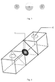
- the right-angle reflecting prism may be a double-path reflecting prism. That is, the reflecting surface of the right-angle reflecting prism is provided with two curve reflecting surfaces. As shown in Fig. 5 , mark 52 marks a locating guide pin hole, and mark 51 marks a curve reflecting surface.
- the mobile optical fibre connector fixed to the double-path reflecting prism is a double-channel mobile optical fibre connector. That is, the mobile optical fibre connector is a mobile optical fibre connector including two optical fibre coupling tubes. Thus, two paths of rays can be reflected simultaneously.
- the right-angle reflecting prism may be a single-row multi-path reflecting prism. That is, a plurality of curve reflecting surfaces in a single row are provided on an oblique surface of the prism. As shown in Fig. 6 , mark 62 marks a locating guide pin hole, and mark 61 marks a curve reflecting surface.
- the mobile optical fibre connector fixed to the single-row multi-path reflecting prism is a single-row multi-path mobile optical fibre connector. That is, the mobile optical fibre connector is a mobile optical fibre connector including a plurality of optical fibre coupling tubes in a row. Thus, multiple paths of rays in a single row can be reflected simultaneously.
- the right-angle reflecting prism may be a multi-row multi-path reflecting prism. That is, a plurality of rows of curve reflecting surfaces are provided on the oblique surface of the prism. Each row includes a plurality of curve reflecting surfaces. As shown in Fig. 7 , a mark 72 marks a locating guide pin hole, and a mark 71 marks a curve reflecting surface.
- the mobile optical fibre connector fixed to the multi-row multi-path reflecting prism is a multi-row multi-path mobile optical fibre connector. That is, the mobile optical fibre connector is a mobile optical fibre connector including a plurality of rows of optical fibre coupling tubes, each row including a plurality of optical fibre coupling tubes. Thus, multiple rows and multiple paths of rays can be reflected simultaneously.
- a method for manufacturing an optical coupling device is provided.
- Fig. 8 shows a flowchart of the manufacturing method, and the manufacturing method includes the steps as follows.
- Step 801 A reflecting surface of a right-angle reflecting prism is provided with a curve reflecting surface.
- the right-angle reflecting prism may be made by adopting an optical polishing technology, a central position and interval of the right-angle reflecting prism is identical to a central position and interval of an optical fibre coupling tube in an mobile optical fibre connector to be fixed to the right-angle reflecting prism; and a diameter and position of a locating guide pin hole in the right-angle reflecting prism is matched with a diameter and position of a locating guide pin hole in the mobile optical fibre connector to be fixed to the right-angle reflecting prism, thereby better connecting the mobile optical fibre connector to the right-angle reflecting prism via a locating guide pin.
- a central position and interval of the provided curve reflecting surface are identical to a central position and interval of the optical fibre coupling tube in the mobile optical fibre connector to be fixed to the right-angle reflecting prism.
- a curvature of the curve reflecting surface may be designed according to a value of an aperture parameter of an optical fibre, and the curve reflecting surface has a gathering function for light beams according to a principle of optical reflection.
- the curvature of the curve reflecting surface of the right-angle reflecting prism is necessary to be designed to ensure that rays incident to the curve reflecting surface from the optical fibre at a maximum angle is gathered by the curve reflecting surface and then reflected in parallel; and a surface type of the reflecting surface optionally includes (but not limited to): a circular arc surface, a paraboloid and the like.
- the reflecting surface is processed on the right-angle reflecting prism by using an ultraviolet laser ablation process, a carbon dioxide laser hot-melting process, a mechanical grinding process or an ultrasonic grinding process.
- the curve reflecting surface may be coated with a film in a vacuum manner to obtain a total reflection curve surface; and specifically, the coated film may be a gold thin film, a silver thin film or other metal thin films, or may be other medium thin films.
- Step 802 The right-angle reflecting prism is fixed to the surface of the mobile optical fibre connector, so that rays propagated by the optical fibre are all exactly incident on the curve reflecting surface of the right-angle reflecting prism.
- locating guide pin holes in the right-angle reflecting prism manufactured in Step 801 and the mobile optical fibre connector are connected via a locating guide pin.
- the right-angle reflecting prism is fixed to the surface of the mobile optical fibre connector via a ultraviolet glue; and specifically, the ultraviolet glue may be applied to a joint between the locating guide pin and the right-angle reflecting prism and a joint between the locating guide pin and the mobile optical fibre connector; or can be applied to an area, connected to the mobile optical fibre connector, at an edge of the prism.
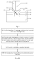
- an optical coupling unit is provided. As shown in Fig. 9 , the optical coupling unit includes the optical coupling device and an optical waveguide 91.
- the optical coupling device is vertically inserted into the optical waveguide 91, so that rays reflected by a curve reflecting surface in the optical coupling device are incident into the optical waveguide 91 and propagated.
- the optical waveguide 91 includes a planar optical waveguide substrate 95, a lower optical waveguide cladding material 94, an optical waveguide core material 93 and an upper optical waveguide cladding material 92.
- the optical coupling device being vertically inserted into the optical waveguide 91 refers to that: a groove is provided at a position above the planar optical waveguide substrate 95 in the optical waveguide 91, so that the right-angle reflecting prism 23 in the optical coupling device is vertically inserted into the groove.
- the size of the groove is required to be greater than the size of the right-angle reflecting prism. That is, the entire right-angle reflecting prism 23 can be put into the groove.
- the length of the optical waveguide may be selected according to actual circuit requirements.
- the type of the optical waveguide may be selected according to the type of the right-angle reflecting prism in the optical coupling device. Specifically, when the right-angle reflecting prism is a double-path reflecting prism, the optical waveguide is selected as a double-path optical waveguide. Thus, when the optical coupling device is vertically inserted into the optical waveguide, a two-path optical fibre and a two-path optical waveguide may be aligned, thereby achieving vertical optical coupling of a double-channel optical fibre and the optical waveguide. When the right-angle reflecting prism is a single-row multi-path reflecting prism, the optical waveguide is selected as a single-row multi-path optical waveguide.
- a single-row multi-path optical fibre and a single-row multi-path optical waveguide may be aligned, thereby achieving vertical optical coupling of the single-row multi-path optical fibre and the optical waveguide.
- the optical waveguide is selected as a double-row multi-path optical waveguide.
- a curvature of the curve reflecting surface 24 of the right-angle reflecting prism 23 in the optical coupling device may be designed according to a value of an aperture parameter of the optical fibre and a value of an aperture parameter of the optical waveguide, and the curve surface has a gathering function for light beams according to a principle of optical reflection.
- the curvature of the reflecting surface 24 of the right-angle reflecting prism 23 is necessary to be designed to ensure that after the rays incident to the curve reflecting surface 24 from the optical fibre at a maximum angle is gathered by the curve reflecting surface 24, an angle of reflected ray is smaller than an angle corresponding to the value of an aperture parameter of the optical waveguide, that is, there is no loss of light energy.
- the surface type of the curve reflecting surface optionally includes, but not limited to, a circular arc surface, a paraboloid and the like.
- the optical coupling unit provided according to at least one embodiment of the present disclosure, after incident rays 910 transmitted by the optical fibre are totally reflected by the curve reflecting surface 24 of the right-angle reflecting prism, parallel reflected lights 211 will be obtained due to the gathering function, and the parallel emergent lights 211 are injected into the optical waveguide and is propagated via the optical waveguide.
- an optical loss can be greatly reduced, thereby achieving high-efficient vertical optical coupling between the optical fibre and the optical waveguide.
- a method for manufacturing an optical coupling unit includes the steps as follows.
- a reflecting surface of a right-angle reflecting prism is provided with a curve reflecting surface.
- the right-angle reflecting prism may be made by adopting an optical polishing technology, and a locating guide pin hole is provided on the right-angle reflecting prism, so that a diameter and position of the locating guide pin hole is matched with a diameter and position of a locating guide pin hole in an mobile optical fibre connector.
- the reflecting surface of the right-angle reflecting prism is provided with the curve reflecting surface, so that a central position and interval of the provided curve reflecting surface correspond to a central position and interval of an optical fibre coupling tube in the mobile optical fibre connector to be fixed to the right-angle reflecting prism.
- a curvature and surface type of the curve reflecting surface are determined so as to determine a curve reflecting surface structure.
- the curvature of the curve reflecting surface may be designed according to a value of an aperture parameter of the mobile optical fibre connector and a value of an aperture parameter of an optical waveguide, and specifically, the curve surface has a gathering function for light beams according to a principle of optical reflection.
- the curvature of the reflecting surface of the right-angle reflecting prism is necessary to be designed to ensure that after rays incident to the right-angle reflecting prism from an optical fibre at a maximum angle are gathered by the curve reflecting surface, an angle of reflection into the optical waveguide is smaller than an angle corresponding to a value of an aperture parameter of the optical waveguide, that is, there is no loss of light energy.
- the surface type of the curve reflecting surface optionally includes, but not limited to, a circular arc surface, a paraboloid and the like.
- the reflecting surface is processed on the right-angle reflecting prism by using an ultraviolet laser ablation process, a carbon dioxide laser hot-melting process, a mechanical grinding process or an ultrasonic grinding process.
- the curve reflecting surface may be coated with a film in a vacuum manner to obtain a total reflection curve surface; and specifically, the curve reflecting surface may be coated with a gold thin film, a silver thin film or other metal thin films, or can be coated with other medium thin films.
- Step 1002 The right-angle reflecting prism is fixed to the surface of the mobile optical fibre connector, so that rays propagated by the optical fibre are all exactly incident on the curve reflecting surface of the right-angle reflecting prism to form an optical coupling device.
- locating guide pin holes matched with the right-angle reflecting prism and the mobile optical fibre connector are connected via a locating guide pin.
- the right-angle reflecting prism is fixed to the surface of the mobile optical fibre connector via a ultraviolet glue; and specifically, the ultraviolet glue may be applied to a joint between the guide pin and the reflecting prism and a joint between the guide pin and the mobile optical fibre connector; or may be applied to an area, connected to the mobile optical fibre connector, at an edge of the prism.
- Step 1003 A groove is provided on the optical waveguide.
- the groove being provided on the optical waveguide includes that: a groove is provided at a position above a planar optical waveguide substrate in the optical waveguide by utilizing ultraviolet laser on the basis of a laser ablation technology.
- the size of the groove is greater than or equal to the size of the right-angle reflecting prism. That is, the entire right-angle reflecting prism can be put into the groove.
- Step 1004 The optical coupling device formed in Step 1002 is inserted into the groove provided in Step 1003 and fixed.
- Fixing may be performed in multiple modes, including, but not limited to, adhesion fixing via ultraviolet glue.
Landscapes
- Physics & Mathematics (AREA)
- General Physics & Mathematics (AREA)
- Optics & Photonics (AREA)
- Electromagnetism (AREA)
- Engineering & Computer Science (AREA)
- Computer Networks & Wireless Communication (AREA)
- Signal Processing (AREA)
- Optical Couplings Of Light Guides (AREA)
- Optical Integrated Circuits (AREA)
Abstract
Description
- The present disclosure relates to the field of optical communications, and in particular to an optical coupling device and an optical coupling unit.
- As requirements for interconnection bandwidths between printed circuit boards and between chips in the application fields (broadband communication networks, super computers, big data centres and the like) are continuously increased, bottlenecks of an electrical interconnection technology based on a printed circuit board gradually emerge on a transmission rate. Particularly, for medium and short distances (0.3m to 1m), electrical interconnection may merely achieve 10Gbps-rate transmission mostly, and interconnection at a high speed such as 25Gbps, 40Gbps and the like has encountered the bottlenecks about the transmission rate. Consequently, the industry proposes that a copper wire used for connecting to form a circuit is replaced with an optical waveguide, and the optical waveguide is integrated on the printed circuit board to achieve optical interconnection between various circuit elements, so as to achieve high-speed data transmission. An optical interconnection method based on an optical waveguide has the advantages of high bandwidth, high density, high transmission speed, low transmission power consumption, low loss, basic avoidance of crosstalk, electromagnetic compatibility and the like. Thus, replacement of an electric printed backboard with an optical printed backboard based on an optical waveguide has become a general trend of high-speed and broadband interconnection development and is a core technology for solving the problem about interconnection bandwidths of the broadband communication networks, the super computers and the big data centres in the future.
- In an interconnection optical waveguide system, there exist a great number of optical path transfer links, such as an optical path transfer between an optical source and an optical waveguide, an optical path transfer between an optical fibre and an optical waveguide and an optical path transfer between two optical waveguides. Therein, optical coupling efficiency is a most concerned factor as the magnitude of coupling efficiency will directly affect the insertion loss of an optical interconnection link, thereby causing shortening of an interconnection distance. Thus, an optical coupling related device plays an important role in the interconnection optical waveguide system, and is an important link for determining the performance of the interconnection system.
- So far, there are many methods for implementing the optical coupling related device. However, there is not a standard solution for vertically optical coupling of an interconnection optical waveguide.
- In order to solve the technical problems existing currently, the embodiments of the present disclosure provide an optical coupling device and an optical coupling unit.
- An optical coupling device is provided in an embodiment of the present disclosure, including: a right-angle reflecting prism and an mobile optical fibre connector, wherein a reflecting surface of the right-angle reflecting prism is provided with a curve reflecting surface, the curve reflecting surface being used for gathering and reflecting rays propagated by an optical fibre; and the mobile optical fibre connector is fixed to the right-angle reflecting prism, to make the rays propagated by the optical fibre being incident on the curve reflecting surface of the right-angle reflecting prism.
- In an example embodiment, the mobile optical fibre connector is provided with an optical fibre coupling tube, and a central position and an interval of the curve reflecting surface are identical to a central position and an interval of the optical fibre coupling tube.
- In an example embodiment, a curvature of the curve reflecting surface is designed according to a value of an aperture parameter of the optical fibre coupling tube, to make rays incident on the curve reflecting surface from the optical fibre at a maximum incident angle being gathered by the curve reflecting surface and then reflected in parallel.
- In an example embodiment, when a type of the right-angle reflecting prism of the optical coupling device is a single-path reflecting prism, a double-path reflecting prism, a single-row multi-path reflecting prism or a double-row multi-path reflecting prism in sequence, a type of the mobile optical fibre connector used for fixing the right-angle reflecting prism is a single-row mobile optical fibre connector, a double-path mobile optical fibre connector, a single-row multi-path mobile optical fibre connector or a double-row multi-path mobile optical fibre connector in sequence.
- In an example embodiment, a diameter and position of a locating guide pin hole of the right-angle reflecting prism correspond to a diameter and position of a locating guide pin hole of the mobile optical fibre connector.
- In an example embodiment, the mobile optical fibre connector is connected to the right-angle reflecting prism via a locating guide pin, and the locating guide pin is connected to the locating guide pin hole in the right-angle reflecting prism and the locating guide pin hole in the mobile optical fibre connector respectively; and the right-angle reflecting prism is fixed to a surface of the mobile optical fibre connector via ultraviolet glue, and the ultraviolet glue is applied to a joint between the locating guide pin and the right-angle reflecting prism, and a joint between the locating guide pin and the mobile optical fibre connector; or applied to an area, connected to the mobile optical fibre connector, at an edge of the right-angle reflecting prism.
- An optical coupling unit is provided in another embodiment of the present disclosure, including an optical waveguide and the optical coupling device as claimed in any one of claims 1 to 6, wherein the optical coupling device is provided being vertically inserted into the optical waveguide, to make rays reflected by the curve reflecting surface on the right-angle reflecting prism in the optical coupling device being incident in the optical waveguide and propagated.
- In an example embodiment, the optical coupling device being vertically inserted into the optical waveguide includes: a groove being provided at a position above a planar optical waveguide substrate in the optical waveguide, the right-angle reflecting prism in the optical coupling device being vertically inserted into the groove, and a size of the groove being greater than or equal to a size of the right-angle reflecting prism.
- In an example embodiment, when a type of the right-angle reflecting prism in the optical coupling device is a single-path reflecting prism, a double-path reflecting prism, a single-row multi-path reflecting prism or a double-row multi-path reflecting prism in sequence, a type of the optical waveguide is a single-path optical waveguide, a double-path optical waveguide, a single-row multi-path optical waveguide or a double-row multi-path optical waveguide in sequence.
- In an example embodiment, a curvature of the curve reflecting surface of the right-angle reflecting prism in the optical coupling device is designed according to a value of an aperture parameter of an optical fibre coupling tube and a value of an aperture parameter of the optical waveguide, to make rays incident on the curve reflecting surface from the optical fibre at a maximum incident angle being gathered by the curve reflecting surface, and an angle of the reflected ray being smaller than an angle corresponding to an value of an aperture of the optical waveguide.
- In an optical coupling device and an optical coupling unit provided by embodiments of the present disclosure, a reflecting surface of a right-angle reflecting prism is provided with a curve reflecting surface, and a mobile optical fibre connector in the optical coupling device is fixed to the right-angle reflecting prism, so that the rays propagated by the optical fibre are incident on the curve reflecting surface, thereby gathering and reflecting the rays propagated by the optical fibre. Thus, the loss of optical propagation can be reduced, and the optical coupling efficiency is improved; and moreover, the optical coupling device and the optical coupling unit provided by the embodiments of the present disclosure have simple structures, and manufacturing methods are simple and easy to operate.
-
-
Fig. 1 is a cross-section view of a right-angle reflecting prism in a related art; -
Fig. 2 is a section view of an optical coupling device provided by at least one embodiment of the present disclosure; -
Fig. 3 is a cross-section view of a mobile optical fibre connector provided by at least one embodiment of the present disclosure; -
Fig. 4 is a three-dimensional structure diagram of a right-angle reflecting prism provided by at least one embodiment of the present disclosure; -
Fig. 5 is a three-dimensional structure diagram of a double-path reflecting prism provided by at least one embodiment of the present disclosure; -
Fig. 6 is a three-dimensional structure diagram of a single-row multi-path reflecting prism provided by at least one embodiment of the present disclosure; -
Fig. 7 is a three-dimensional structure diagram of a multi-row multi-path reflecting prism provided by at least one embodiment of the present disclosure; -
Fig. 8 is a flowchart of a method for manufacturing an optical coupling device provided by at least one embodiment of the present disclosure; -
Fig. 9 is a section view of an optical coupling unit provided by at least one embodiment of the present disclosure; and -
Fig. 10 is a flowchart of a method for manufacturing an optical coupling unit provided by at least one embodiment of the present disclosure. - In at least one embodiment of the present disclosure, an optical coupling device including a mobile optical fibre connector and a right-angle reflecting prism is provided. A reflecting surface of the right-angle reflecting prism is provided with a curve reflecting surface, and the mobile optical fibre connector is fixed to the right-angle reflecting prism, so that rays propagated by an optical fibre are incident on the curve reflecting surface, thereby gathering and reflecting the rays propagated by the optical fibre. Thus, the loss of optical propagation can be reduced, and the optical coupling efficiency can be improved.
- The present disclosure is further described below with reference to the drawings and specific embodiments in detail.
-
Fig. 1 is a cross-section view of a right-angle reflecting prism. InFig. 1 , two right-angle sides AB and AC represent two side surfaces, vertical to each other, on the right-angle reflecting prism, and BC represents a reflecting surface on the right-angle reflecting prism. - According to at least one embodiment of the present disclosure, an optical coupling device is provided.
Fig. 2 is a section view of an optical coupling device according to an embodiment of the present disclosure. As shown inFig. 2 , the optical coupling device includes a mobileoptical fibre connector 21 and a right-angle reflecting prism 23. A reflecting surface of the right-angle reflecting prism 23 is provided with acurve reflecting surface 24, and thecurve reflecting surface 24 is configured to gather and reflect the rays incident on thecurve reflecting surface 24; the mobileoptical fibre connector 21 is fixed to the right-angle reflecting prism 23; and the mobileoptical fibre connector 21 includes an opticalfibre coupling tube 22, and the opticalfibre coupling tube 22 is configured to fix and align an optical fibre, so that the rays propagated by the optical fibre are incident on thecurve reflecting surface 24 of the right-angle reflecting prism 23. - In an example embodiment, the
curve reflecting surface 24 is coated with a high-reflectivity optical thin film, the optical thin film on thecurve reflecting surface 24 may be a gold thin film, a silver thin film or other metal thin films, or may be other medium thin films; the film-coatedcurve reflecting surface 24 can achieve higher reflectivity, thereby totally reflecting incident rays; and when the optical fibre is fixed inside the opticalfibre coupling tube 22 in the mobileoptical fibre connector 21, the incident rays transmitted by the optical fibre are incident on thecurve reflecting surface 24 of the right-angle reflecting prism, and then the incident rays are reflected by thecurve reflecting surface 24 coated with the high-reflectivity optical thin film. - In at least one embodiment of the present disclosure, the type and structure of the mobile
optical fibre connector 21 are not specially required, and the type of the mobileoptical fibre connector 21 includes (but not limited to): Mechanical Transfer Registered Jack (MT-RJ) or Multi-fibre Push On (MPO), which makes the optical coupling device provided by the embodiment of the present disclosure simple in structure and easy to implement. -
Fig. 3 is a cross-section view of a mobileoptical fibre connector 21. A part A filled with transverse lines is a cross section of the opticalfibre coupling tube 22, and part B and part C filled with oblique lines show two locating guide pin holes.Fig. 4 is a three-dimensional structure diagram of a right-angle reflecting prism 23 provided by at least one embodiment of the present disclosure. Amark 41 marks a position of the curve reflecting surface, and amark 42 marks a position of a locating guide pin hole. In practical application, the number and positions of locating guide pin holes in the mobileoptical fibre connector 21 and the right-angle reflecting prism 23 may be designed as required, and not limited to the structure provided by the embodiment of the present disclosure. - In practical application, a central position and interval of the
curve reflecting surface 24 of the right-angle reflecting prism 23 is identical to a central position and interval of the opticalfibre coupling tube 22 in the selected mobileoptical fibre connector 21. - The diameter and position of the locating guide pin hole in the right-
angle reflecting prism 23 is matched with the diameter and position of the locating guide pin hole in the selected mobileoptical fibre connector 21, thereby better connecting the mobileoptical fibre connector 21 to the right-angle reflecting prism 23 via the locating guide pin. - As shown in
Fig. 2 , the right-angle reflecting prism 23 is fixed to the surface of the mobileoptical fibre connector 21, so that the rays transmitted by the optical fibre are exactly incident on thecurve reflecting surface 24 of the right-angle reflecting prism 23 and are reflected by thecurve reflecting surface 24. - In an example embodiment, the mobile
optical fibre connector 21 being fixed to the right-angle reflecting prism 23 includes that: the right-angle reflecting prism 23 is connected to the mobileoptical fibre connector 21 via the locating guide pin, the locating guide pin being connected to the locating guide pin holes in the right-angle reflecting prism 23 and the mobileoptical fibre connector 21 respectively; and in addition, the right-angle reflecting prism 23 is fixed to the surface of the mobileoptical fibre connector 21 via a ultraviolet glue, and the ultraviolet glue can be applied to a joint between the locating guide pin and the right-angle reflecting prism 23 and a joint between the locating guide pin and the mobileoptical fibre connector 21; or can be applied to an area, connected to the mobileoptical fibre connector 21, at an edge of the right-angle reflecting prism 23. - In practical application, a curvature of the
curve reflecting surface 24 of the right-angle reflecting prism 23 can be designed according to a value of an aperture parameter of the optical fibre, and thecurve reflecting surface 24 has a gathering function for light beams according to a principle of optical reflection. Thus, the curvature of thecurve reflecting surface 24 of the right-angle reflecting prism 23 is designed to ensure that the rays incident to the right-angle reflecting prism 23 from the optical fibre at a maximum angle can be gathered by thecurve reflecting surface 24 and then reflected in parallel; and the surface type of the reflecting surface optionally includes (but not limited to): a circular arc surface, a paraboloid and the like. - As shown in
Fig. 2 , afterincident rays 210 transmitted by the optical fibre are totally reflected by thecurve reflecting surface 24 of the right-angle reflecting prism, parallel reflectedlight 211 will be obtained due to the gathering function. Thus, an optical loss caused by the divergence of rays when a common reflecting prism is used can be reduced, thereby improving the optical coupling efficiency. - In at least one embodiment of the present disclosure, the right-angle reflecting prism may be a double-path reflecting prism. That is, the reflecting surface of the right-angle reflecting prism is provided with two curve reflecting surfaces. As shown in
Fig. 5 , mark 52 marks a locating guide pin hole, and mark 51 marks a curve reflecting surface. Correspondingly, the mobile optical fibre connector fixed to the double-path reflecting prism is a double-channel mobile optical fibre connector. That is, the mobile optical fibre connector is a mobile optical fibre connector including two optical fibre coupling tubes. Thus, two paths of rays can be reflected simultaneously. - In at least one embodiment of the present disclosure, the right-angle reflecting prism may be a single-row multi-path reflecting prism. That is, a plurality of curve reflecting surfaces in a single row are provided on an oblique surface of the prism. As shown in
Fig. 6 , mark 62 marks a locating guide pin hole, and mark 61 marks a curve reflecting surface. Correspondingly, the mobile optical fibre connector fixed to the single-row multi-path reflecting prism is a single-row multi-path mobile optical fibre connector. That is, the mobile optical fibre connector is a mobile optical fibre connector including a plurality of optical fibre coupling tubes in a row. Thus, multiple paths of rays in a single row can be reflected simultaneously. - In at least one embodiment of the present disclosure, the right-angle reflecting prism may be a multi-row multi-path reflecting prism. That is, a plurality of rows of curve reflecting surfaces are provided on the oblique surface of the prism. Each row includes a plurality of curve reflecting surfaces. As shown in
Fig. 7 , amark 72 marks a locating guide pin hole, and amark 71 marks a curve reflecting surface. The mobile optical fibre connector fixed to the multi-row multi-path reflecting prism is a multi-row multi-path mobile optical fibre connector. That is, the mobile optical fibre connector is a mobile optical fibre connector including a plurality of rows of optical fibre coupling tubes, each row including a plurality of optical fibre coupling tubes. Thus, multiple rows and multiple paths of rays can be reflected simultaneously. - According to at least one embodiment of the present disclosure, a method for manufacturing an optical coupling device is provided.
Fig. 8 shows a flowchart of the manufacturing method, and the manufacturing method includes the steps as follows. - Step 801: A reflecting surface of a right-angle reflecting prism is provided with a curve reflecting surface.
- Here, the right-angle reflecting prism may be made by adopting an optical polishing technology, a central position and interval of the right-angle reflecting prism is identical to a central position and interval of an optical fibre coupling tube in an mobile optical fibre connector to be fixed to the right-angle reflecting prism; and a diameter and position of a locating guide pin hole in the right-angle reflecting prism is matched with a diameter and position of a locating guide pin hole in the mobile optical fibre connector to be fixed to the right-angle reflecting prism, thereby better connecting the mobile optical fibre connector to the right-angle reflecting prism via a locating guide pin.
- In an example embodiment, a central position and interval of the provided curve reflecting surface are identical to a central position and interval of the optical fibre coupling tube in the mobile optical fibre connector to be fixed to the right-angle reflecting prism. A curvature of the curve reflecting surface may be designed according to a value of an aperture parameter of an optical fibre, and the curve reflecting surface has a gathering function for light beams according to a principle of optical reflection. Thus, the curvature of the curve reflecting surface of the right-angle reflecting prism is necessary to be designed to ensure that rays incident to the curve reflecting surface from the optical fibre at a maximum angle is gathered by the curve reflecting surface and then reflected in parallel; and a surface type of the reflecting surface optionally includes (but not limited to): a circular arc surface, a paraboloid and the like. According to a designed curve structure, the reflecting surface is processed on the right-angle reflecting prism by using an ultraviolet laser ablation process, a carbon dioxide laser hot-melting process, a mechanical grinding process or an ultrasonic grinding process.
- Wherein, the curve reflecting surface may be coated with a film in a vacuum manner to obtain a total reflection curve surface; and specifically, the coated film may be a gold thin film, a silver thin film or other metal thin films, or may be other medium thin films.
- Step 802: The right-angle reflecting prism is fixed to the surface of the mobile optical fibre connector, so that rays propagated by the optical fibre are all exactly incident on the curve reflecting surface of the right-angle reflecting prism.
- In an example embodiment, locating guide pin holes in the right-angle reflecting prism manufactured in Step 801 and the mobile optical fibre connector are connected via a locating guide pin. In addition, the right-angle reflecting prism is fixed to the surface of the mobile optical fibre connector via a ultraviolet glue; and specifically, the ultraviolet glue may be applied to a joint between the locating guide pin and the right-angle reflecting prism and a joint between the locating guide pin and the mobile optical fibre connector; or can be applied to an area, connected to the mobile optical fibre connector, at an edge of the prism.
- It is important to note that the sequence numbers of the above steps are merely intended to distinguish different steps and do not limit the sequence of the steps. When all steps are executed, there is not a strict sequence.
- According to at least one embodiment of the present disclosure, an optical coupling unit is provided. As shown in
Fig. 9 , the optical coupling unit includes the optical coupling device and anoptical waveguide 91. The optical coupling device is vertically inserted into theoptical waveguide 91, so that rays reflected by a curve reflecting surface in the optical coupling device are incident into theoptical waveguide 91 and propagated. - As shown in
Fig. 9 , theoptical waveguide 91 includes a planaroptical waveguide substrate 95, a lower opticalwaveguide cladding material 94, an opticalwaveguide core material 93 and an upper opticalwaveguide cladding material 92. The optical coupling device being vertically inserted into theoptical waveguide 91 refers to that: a groove is provided at a position above the planaroptical waveguide substrate 95 in theoptical waveguide 91, so that the right-angle reflecting prism 23 in the optical coupling device is vertically inserted into the groove. The size of the groove is required to be greater than the size of the right-angle reflecting prism. That is, the entire right-angle reflecting prism 23 can be put into the groove. - In an example embodiment, the length of the optical waveguide may be selected according to actual circuit requirements. The type of the optical waveguide may be selected according to the type of the right-angle reflecting prism in the optical coupling device. Specifically, when the right-angle reflecting prism is a double-path reflecting prism, the optical waveguide is selected as a double-path optical waveguide. Thus, when the optical coupling device is vertically inserted into the optical waveguide, a two-path optical fibre and a two-path optical waveguide may be aligned, thereby achieving vertical optical coupling of a double-channel optical fibre and the optical waveguide. When the right-angle reflecting prism is a single-row multi-path reflecting prism, the optical waveguide is selected as a single-row multi-path optical waveguide. Thus, when the optical coupling device is vertically inserted into the optical waveguide, a single-row multi-path optical fibre and a single-row multi-path optical waveguide may be aligned, thereby achieving vertical optical coupling of the single-row multi-path optical fibre and the optical waveguide. When the right-angle reflecting prism is a double-row multi-path reflecting prism, the optical waveguide is selected as a double-row multi-path optical waveguide. Thus, when the optical coupling device is vertically inserted into the optical waveguide, a double-row multi-path optical fibre and a double-row multi-path optical waveguide may be aligned, thereby achieving vertical optical coupling of the double-row multi-path optical fibre and the optical waveguide.
- In an example embodiment, a curvature of the
curve reflecting surface 24 of the right-angle reflecting prism 23 in the optical coupling device may be designed according to a value of an aperture parameter of the optical fibre and a value of an aperture parameter of the optical waveguide, and the curve surface has a gathering function for light beams according to a principle of optical reflection. Thus, the curvature of the reflectingsurface 24 of the right-angle reflecting prism 23 is necessary to be designed to ensure that after the rays incident to thecurve reflecting surface 24 from the optical fibre at a maximum angle is gathered by thecurve reflecting surface 24, an angle of reflected ray is smaller than an angle corresponding to the value of an aperture parameter of the optical waveguide, that is, there is no loss of light energy. The surface type of the curve reflecting surface optionally includes, but not limited to, a circular arc surface, a paraboloid and the like. - As shown in
Fig. 9 , in the optical coupling unit provided according to at least one embodiment of the present disclosure, after incident rays 910 transmitted by the optical fibre are totally reflected by thecurve reflecting surface 24 of the right-angle reflecting prism, parallel reflectedlights 211 will be obtained due to the gathering function, and the parallelemergent lights 211 are injected into the optical waveguide and is propagated via the optical waveguide. Thus, an optical loss can be greatly reduced, thereby achieving high-efficient vertical optical coupling between the optical fibre and the optical waveguide. - According to at least one embodiment of the present disclosure, a method for manufacturing an optical coupling unit is provided. As shown in
Fig. 10 , the method includes the steps as follows. - 1001: A reflecting surface of a right-angle reflecting prism is provided with a curve reflecting surface.
- In an example embodiment, the right-angle reflecting prism may be made by adopting an optical polishing technology, and a locating guide pin hole is provided on the right-angle reflecting prism, so that a diameter and position of the locating guide pin hole is matched with a diameter and position of a locating guide pin hole in an mobile optical fibre connector.
- The reflecting surface of the right-angle reflecting prism is provided with the curve reflecting surface, so that a central position and interval of the provided curve reflecting surface correspond to a central position and interval of an optical fibre coupling tube in the mobile optical fibre connector to be fixed to the right-angle reflecting prism.
- A curvature and surface type of the curve reflecting surface are determined so as to determine a curve reflecting surface structure.
- In an example embodiment, the curvature of the curve reflecting surface may be designed according to a value of an aperture parameter of the mobile optical fibre connector and a value of an aperture parameter of an optical waveguide, and specifically, the curve surface has a gathering function for light beams according to a principle of optical reflection. Thus, the curvature of the reflecting surface of the right-angle reflecting prism is necessary to be designed to ensure that after rays incident to the right-angle reflecting prism from an optical fibre at a maximum angle are gathered by the curve reflecting surface, an angle of reflection into the optical waveguide is smaller than an angle corresponding to a value of an aperture parameter of the optical waveguide, that is, there is no loss of light energy. The surface type of the curve reflecting surface optionally includes, but not limited to, a circular arc surface, a paraboloid and the like.
- According to the designed curve structure, the reflecting surface is processed on the right-angle reflecting prism by using an ultraviolet laser ablation process, a carbon dioxide laser hot-melting process, a mechanical grinding process or an ultrasonic grinding process.
- Wherein, the curve reflecting surface may be coated with a film in a vacuum manner to obtain a total reflection curve surface; and specifically, the curve reflecting surface may be coated with a gold thin film, a silver thin film or other metal thin films, or can be coated with other medium thin films.
- Step 1002: The right-angle reflecting prism is fixed to the surface of the mobile optical fibre connector, so that rays propagated by the optical fibre are all exactly incident on the curve reflecting surface of the right-angle reflecting prism to form an optical coupling device.
- In an example embodiment, locating guide pin holes matched with the right-angle reflecting prism and the mobile optical fibre connector are connected via a locating guide pin. In addition, the right-angle reflecting prism is fixed to the surface of the mobile optical fibre connector via a ultraviolet glue; and specifically, the ultraviolet glue may be applied to a joint between the guide pin and the reflecting prism and a joint between the guide pin and the mobile optical fibre connector; or may be applied to an area, connected to the mobile optical fibre connector, at an edge of the prism.
- Step 1003: A groove is provided on the optical waveguide.
- In an example embodiment, the groove being provided on the optical waveguide includes that: a groove is provided at a position above a planar optical waveguide substrate in the optical waveguide by utilizing ultraviolet laser on the basis of a laser ablation technology. The size of the groove is greater than or equal to the size of the right-angle reflecting prism. That is, the entire right-angle reflecting prism can be put into the groove.
- Step 1004: The optical coupling device formed in
Step 1002 is inserted into the groove provided in Step 1003 and fixed. - Fixing may be performed in multiple modes, including, but not limited to, adhesion fixing via ultraviolet glue. By inserting and fixing the optical coupling device into the groove of the optical waveguide, optical vertical coupling can be achieved.
- It is important to note that the sequence numbers of the above steps are merely intended to distinguish different steps and do not limit the sequence of the steps. When all steps are executed, there is not a strict sequence.
- The above is merely example embodiments of the present disclosure, and is not intended to limit the protection scope of the present disclosure.
Claims (10)
- An optical coupling device, comprising: a right-angle reflecting prism and an mobile optical fibre connector, wherein
a reflecting surface of the right-angle reflecting prism is provided with a curve reflecting surface, the curve reflecting surface being used for gathering and reflecting rays propagated by an optical fibre; and
the mobile optical fibre connector is fixed to the right-angle reflecting prism, to make the rays propagated by the optical fibre being incident on the curve reflecting surface of the right-angle reflecting prism. - The optical coupling device as claimed in claim 1, wherein the mobile optical fibre connector is provided with an optical fibre coupling tube, and a central position and an interval of the curve reflecting surface are identical to a central position and an interval of the optical fibre coupling tube.
- The optical coupling device as claimed in claim 2, wherein a curvature of the curve reflecting surface is designed according to a value of an aperture parameter of the optical fibre coupling tube, to make rays incident on the curve reflecting surface from the optical fibre at a maximum incident angle being gathered by the curve reflecting surface and then reflected in parallel.
- The optical coupling device as claimed in claim 3, wherein when a type of the right-angle reflecting prism of the optical coupling device is a single-path reflecting prism, a double-path reflecting prism, a single-row multi-path reflecting prism or a double-row multi-path reflecting prism in sequence, a type of the mobile optical fibre connector used for fixing the right-angle reflecting prism is a single-row mobile optical fibre connector, a double-path mobile optical fibre connector, a single-row multi-path mobile optical fibre connector or a double-row multi-path mobile optical fibre connector in sequence.
- The optical coupling device as claimed in claim 1, wherein a diameter and position of a locating guide pin hole of the right-angle reflecting prism correspond to a diameter and position of a locating guide pin hole of the mobile optical fibre connector.
- The optical coupling device as claimed in claim 5, wherein the mobile optical fibre connector is connected to the right-angle reflecting prism via a locating guide pin, and the locating guide pin is connected to the locating guide pin hole in the right-angle reflecting prism and the locating guide pin hole in the mobile optical fibre connector respectively; and
the right-angle reflecting prism is fixed to a surface of the mobile optical fibre connector via ultraviolet glue, and the ultraviolet glue is applied to a joint between the locating guide pin and the right-angle reflecting prism, and a joint between the locating guide pin and the mobile optical fibre connector; or applied to an area, connected to the mobile optical fibre connector, at an edge of the right-angle reflecting prism. - An optical coupling unit, comprising an optical waveguide and the optical coupling device as claimed in any one of claims 1 to 6, wherein the optical coupling device is provided being vertically inserted into the optical waveguide, to make rays reflected by the curve reflecting surface on the right-angle reflecting prism in the optical coupling device being incident in the optical waveguide and propagated.
- The optical coupling unit as claimed in claim 7, wherein the optical coupling device being vertically inserted into the optical waveguide comprises: a groove being provided at a position above a planar optical waveguide substrate in the optical waveguide, the right-angle reflecting prism in the optical coupling device being vertically inserted into the groove, and a size of the groove being greater than or equal to a size of the right-angle reflecting prism.
- The optical coupling unit as claimed in claim 8, wherein when a type of the right-angle reflecting prism in the optical coupling device is a single-path reflecting prism, a double-path reflecting prism, a single-row multi-path reflecting prism or a double-row multi-path reflecting prism in sequence, a type of the optical waveguide is a single-path optical waveguide, a double-path optical waveguide, a single-row multi-path optical waveguide or a double-row multi-path optical waveguide in sequence.
- The optical coupling unit as claimed in any one of claims 7 to 9, wherein a curvature of the curve reflecting surface of the right-angle reflecting prism in the optical coupling device is designed according to a value of an aperture parameter of an optical fibre coupling tube and a value of an aperture parameter of the optical waveguide, to make rays incident on the curve reflecting surface from the optical fibre at a maximum incident angle being gathered by the curve reflecting surface, and an angle of the reflected ray being smaller than an angle corresponding to an value of an aperture of the optical waveguide.
Applications Claiming Priority (2)
| Application Number | Priority Date | Filing Date | Title |
|---|---|---|---|
| CN201420027992.2U CN204009138U (en) | 2014-01-16 | 2014-01-16 | A kind of Light Coupled Device and optical coupling unit |
| PCT/CN2014/084811 WO2015106567A1 (en) | 2014-01-16 | 2014-08-20 | Optical coupling device and optical coupling unit |
Publications (3)
| Publication Number | Publication Date |
|---|---|
| EP3096164A1 true EP3096164A1 (en) | 2016-11-23 |
| EP3096164A4 EP3096164A4 (en) | 2017-01-25 |
| EP3096164B1 EP3096164B1 (en) | 2025-04-02 |
Family
ID=52049116
Family Applications (1)
| Application Number | Title | Priority Date | Filing Date |
|---|---|---|---|
| EP14878417.6A Active EP3096164B1 (en) | 2014-01-16 | 2014-08-20 | Optical coupling device and optical coupling unit |
Country Status (6)
| Country | Link |
|---|---|
| US (1) | US20160356969A1 (en) |
| EP (1) | EP3096164B1 (en) |
| JP (1) | JP6463780B2 (en) |
| KR (1) | KR20160135707A (en) |
| CN (1) | CN204009138U (en) |
| WO (1) | WO2015106567A1 (en) |
Families Citing this family (10)
| Publication number | Priority date | Publication date | Assignee | Title |
|---|---|---|---|---|
| CN104865653B (en) * | 2015-06-12 | 2016-06-08 | 烽火通信科技股份有限公司 | For the optical module vertical coupled with optoelectronic transceiver array and manufacture method |
| US10168494B2 (en) * | 2016-11-30 | 2019-01-01 | International Business Machines Corporation | Off-axis micro-mirror arrays for optical coupling in polymer waveguides |
| US10197737B2 (en) * | 2017-06-19 | 2019-02-05 | Intel Corporation | Low back reflection echelle grating |
| CN108303767B (en) * | 2018-02-09 | 2019-12-31 | 苏州德睿电力科技有限公司 | A method for preparing a concave mirror on an optical waveguide |
| CN112433643A (en) * | 2019-08-24 | 2021-03-02 | 深圳市凯健奥达科技有限公司 | Surface acoustic wave curve reflection stripe and touch screen using same |
| CN112698448A (en) * | 2019-10-22 | 2021-04-23 | 上海信及光子集成技术有限公司 | Reflection type vertical optical coupling structure based on prism |
| CN115136291B (en) * | 2020-02-17 | 2026-02-03 | 捷普有限公司 | Apparatus, system and method for providing a fiber optic coupler |
| CN113835165B (en) * | 2020-06-24 | 2022-11-25 | 华为技术有限公司 | Light emitting component, chip, optical module and optical communication equipment |
| CN112130130B (en) * | 2020-09-07 | 2024-06-04 | 联合微电子中心有限责任公司 | Silicon optical chip and laser radar system |
| CN116840977A (en) * | 2022-03-24 | 2023-10-03 | 华为技术有限公司 | Optical fiber array, optical module and communication equipment |
Family Cites Families (24)
| Publication number | Priority date | Publication date | Assignee | Title |
|---|---|---|---|---|
| CA2071200A1 (en) * | 1989-12-18 | 1991-06-19 | Jerald Dana Lee | Fiber optic switch having a curved reflector |
| JPH0488308A (en) * | 1990-08-01 | 1992-03-23 | Sumitomo Electric Ind Ltd | Light receiving device |
| US5369529A (en) * | 1993-07-19 | 1994-11-29 | Motorola, Inc. | Reflective optoelectronic interface device and method of making |
| DE19616015C1 (en) * | 1996-04-23 | 1997-06-19 | Bosch Gmbh Robert | Optical transmitting or receiving element coupling arrangement |
| JP2907203B1 (en) * | 1998-02-20 | 1999-06-21 | 住友電気工業株式会社 | Optical module |
| US6421472B1 (en) * | 2000-04-14 | 2002-07-16 | Corning Incorporated | Athermalized polymer overclad integrated planar optical waveguide device and method |
| DE10043996A1 (en) * | 2000-09-05 | 2002-03-14 | Cube Optics Ag | Coupling device and manufacturing method therefor |
| WO2002057821A1 (en) * | 2001-01-19 | 2002-07-25 | Primarion, Inc. | Optical interconnect with integral reflective surface and lens, system including the interconnect and method of forming the same |
| US6704479B2 (en) * | 2001-07-24 | 2004-03-09 | The United States Of America As Represented By The Secretary Of The Navy | Method for coupling light into cladding-pumped fiber sources using an embedded mirror |
| US6697550B2 (en) * | 2001-10-24 | 2004-02-24 | Renka Corporation | Fast 1×N fiber-optic switch |
| FR2836236B1 (en) * | 2002-02-21 | 2004-09-17 | Framatome Connectors Int | IMPROVED OPTOELECTRONIC COUPLING DEVICE |
| US7289701B2 (en) * | 2002-03-14 | 2007-10-30 | Sae Magnetics (Hong Kong) Limited | Integrated platform for passive optical alignment of semiconductor device with optical fiber |
| JP3947481B2 (en) * | 2003-02-19 | 2007-07-18 | 浜松ホトニクス株式会社 | Optical module and manufacturing method thereof |
| JP4348604B2 (en) * | 2003-07-10 | 2009-10-21 | オムロン株式会社 | Optical path conversion type optical coupling element |
| FR2871244A1 (en) * | 2004-06-07 | 2005-12-09 | Fci Sa | OPTICAL COUPLING DEVICE |
| US7239385B2 (en) * | 2004-11-30 | 2007-07-03 | Hutchinson Technology Incorporated | Method and apparatus for monitoring output signal instability in a light source |
| WO2007076888A1 (en) * | 2005-12-30 | 2007-07-12 | Fci | Optical coupling device |
| US20100098374A1 (en) * | 2008-10-20 | 2010-04-22 | Avago Technologies Fiber Ip (Signgapore) Pte. Ltd. | Optoelectronic component based on premold technology |
| JP5564344B2 (en) * | 2010-06-29 | 2014-07-30 | 株式会社フジクラ | Ferrule with optical fiber |
| US9429717B2 (en) * | 2010-06-29 | 2016-08-30 | Fujikura Ltd. | Ferrule and ferrule with optical fiber |
| FR2963113B1 (en) * | 2010-07-23 | 2013-03-29 | Commissariat Energie Atomique | NANOPHOTONIC PLANAR WAVEGUIDE HAVING AN OPTICAL COUPLING STRUCTURE WITH AN OPTICAL FIBER |
| CN102436038B (en) * | 2011-12-27 | 2013-10-09 | 华为技术有限公司 | Optical path coupler, optical path coupling device and optical path coupling method |
| JP2013235243A (en) * | 2012-04-09 | 2013-11-21 | Fujikura Ltd | Optical path changing member |
| US20150146211A1 (en) * | 2013-11-27 | 2015-05-28 | Corning Incorporated | Optical coherence tomography probe |
-
2014
- 2014-01-16 CN CN201420027992.2U patent/CN204009138U/en not_active Expired - Lifetime
- 2014-08-20 WO PCT/CN2014/084811 patent/WO2015106567A1/en not_active Ceased
- 2014-08-20 JP JP2016564364A patent/JP6463780B2/en active Active
- 2014-08-20 KR KR1020167022222A patent/KR20160135707A/en not_active Ceased
- 2014-08-20 US US15/112,336 patent/US20160356969A1/en not_active Abandoned
- 2014-08-20 EP EP14878417.6A patent/EP3096164B1/en active Active
Also Published As
| Publication number | Publication date |
|---|---|
| WO2015106567A1 (en) | 2015-07-23 |
| KR20160135707A (en) | 2016-11-28 |
| CN204009138U (en) | 2014-12-10 |
| EP3096164A4 (en) | 2017-01-25 |
| JP2017503221A (en) | 2017-01-26 |
| JP6463780B2 (en) | 2019-02-06 |
| EP3096164B1 (en) | 2025-04-02 |
| US20160356969A1 (en) | 2016-12-08 |
Similar Documents
| Publication | Publication Date | Title |
|---|---|---|
| EP3096164B1 (en) | Optical coupling device and optical coupling unit | |
| US10429597B2 (en) | Interposer assemblies and arrangements for coupling at least one optical fiber to at least one optoelectronic device | |
| EP3807686B1 (en) | Optical connectors and detachable optical connector assemblies for optical chips | |
| US10365439B2 (en) | Optical interconnect | |
| WO2019184100A1 (en) | Optical module | |
| CN106597612A (en) | Optical templates and communication equipment | |
| CN105372770A (en) | Optical fiber coupling module | |
| US20210247575A1 (en) | Optical Fiber Connection Component and Optical Device Manufacturing Method | |
| JP6561491B2 (en) | Tape fiber connection structure and manufacturing method | |
| WO2016155381A1 (en) | Integrated multi-path optical lens array assembly for parallel optical transceiver module | |
| US8636426B2 (en) | Photoelectric conversion system with optical transceive module | |
| CN110764196B (en) | Pinless Pluggable Alignment Structure for Coupling Fiber Arrays to Planar Optical Waveguides | |
| CN109116469B (en) | Optical module | |
| CN114002772B (en) | A light receiving integrated chip | |
| CN114966975A (en) | A Probe Fiber for Silicon Optical Wafer End-Face Coupling Test | |
| CN204556914U (en) | For the integrated multipath optical lens array assembly of parallel light transceiving module | |
| CN101819300B (en) | Ultrathin connector in high-speed optical interconnection platform | |
| CN207352218U (en) | A double-ended optical fiber array | |
| CN119828298B (en) | A connector and an optical communication system | |
| CN223065557U (en) | An MT ferrule and an 800G SR8 optical engine based on hollow core fiber | |
| Brusberg et al. | Design, fabrication and connectorization of high-performance multimode glass waveguides for board-level optical interconnects | |
| CN120428236A (en) | Laser transceiver system, assembly method and laser radar | |
| CN112368617A (en) | Optical coupling device and packaging method thereof, optical module and communication equipment | |
| CN114578486A (en) | Waveguide-optical fiber coupling device, manufacturing method thereof and optical transmission system | |
| Hwang et al. | A Large Area and 2 Dimensional Optical Interconnection Platform |
Legal Events
| Date | Code | Title | Description |
|---|---|---|---|
| PUAI | Public reference made under article 153(3) epc to a published international application that has entered the european phase |
Free format text: ORIGINAL CODE: 0009012 |
|
| 17P | Request for examination filed |
Effective date: 20160725 |
|
| AK | Designated contracting states |
Kind code of ref document: A1 Designated state(s): AL AT BE BG CH CY CZ DE DK EE ES FI FR GB GR HR HU IE IS IT LI LT LU LV MC MK MT NL NO PL PT RO RS SE SI SK SM TR |
|
| AX | Request for extension of the european patent |
Extension state: BA ME |
|
| A4 | Supplementary search report drawn up and despatched |
Effective date: 20161222 |
|
| RIC1 | Information provided on ipc code assigned before grant |
Ipc: G02B 6/42 20060101AFI20161216BHEP Ipc: H04B 10/25 20130101ALI20161216BHEP Ipc: G02B 6/34 20060101ALI20161216BHEP |
|
| DAX | Request for extension of the european patent (deleted) | ||
| STAA | Information on the status of an ep patent application or granted ep patent |
Free format text: STATUS: EXAMINATION IS IN PROGRESS |
|
| 17Q | First examination report despatched |
Effective date: 20200520 |
|
| GRAP | Despatch of communication of intention to grant a patent |
Free format text: ORIGINAL CODE: EPIDOSNIGR1 |
|
| STAA | Information on the status of an ep patent application or granted ep patent |
Free format text: STATUS: GRANT OF PATENT IS INTENDED |
|
| INTG | Intention to grant announced |
Effective date: 20241111 |
|
| GRAS | Grant fee paid |
Free format text: ORIGINAL CODE: EPIDOSNIGR3 |
|
| GRAA | (expected) grant |
Free format text: ORIGINAL CODE: 0009210 |
|
| STAA | Information on the status of an ep patent application or granted ep patent |
Free format text: STATUS: THE PATENT HAS BEEN GRANTED |
|
| AK | Designated contracting states |
Kind code of ref document: B1 Designated state(s): AL AT BE BG CH CY CZ DE DK EE ES FI FR GB GR HR HU IE IS IT LI LT LU LV MC MK MT NL NO PL PT RO RS SE SI SK SM TR |
|
| REG | Reference to a national code |
Ref country code: GB Ref legal event code: FG4D |
|
| REG | Reference to a national code |
Ref country code: CH Ref legal event code: EP |
|
| REG | Reference to a national code |
Ref country code: IE Ref legal event code: FG4D |
|
| REG | Reference to a national code |
Ref country code: DE Ref legal event code: R096 Ref document number: 602014091760 Country of ref document: DE |
|
| PGFP | Annual fee paid to national office [announced via postgrant information from national office to epo] |
Ref country code: GB Payment date: 20250626 Year of fee payment: 12 |
|
| PGFP | Annual fee paid to national office [announced via postgrant information from national office to epo] |
Ref country code: FR Payment date: 20250610 Year of fee payment: 12 |
|
| REG | Reference to a national code |
Ref country code: NL Ref legal event code: MP Effective date: 20250402 |
|
| PG25 | Lapsed in a contracting state [announced via postgrant information from national office to epo] |
Ref country code: NL Free format text: LAPSE BECAUSE OF FAILURE TO SUBMIT A TRANSLATION OF THE DESCRIPTION OR TO PAY THE FEE WITHIN THE PRESCRIBED TIME-LIMIT Effective date: 20250402 |
|
| REG | Reference to a national code |
Ref country code: AT Ref legal event code: MK05 Ref document number: 1781802 Country of ref document: AT Kind code of ref document: T Effective date: 20250402 |
|
| PG25 | Lapsed in a contracting state [announced via postgrant information from national office to epo] |
Ref country code: ES Free format text: LAPSE BECAUSE OF FAILURE TO SUBMIT A TRANSLATION OF THE DESCRIPTION OR TO PAY THE FEE WITHIN THE PRESCRIBED TIME-LIMIT Effective date: 20250402 Ref country code: FI Free format text: LAPSE BECAUSE OF FAILURE TO SUBMIT A TRANSLATION OF THE DESCRIPTION OR TO PAY THE FEE WITHIN THE PRESCRIBED TIME-LIMIT Effective date: 20250402 Ref country code: PT Free format text: LAPSE BECAUSE OF FAILURE TO SUBMIT A TRANSLATION OF THE DESCRIPTION OR TO PAY THE FEE WITHIN THE PRESCRIBED TIME-LIMIT Effective date: 20250804 |
|
| PGFP | Annual fee paid to national office [announced via postgrant information from national office to epo] |
Ref country code: DE Payment date: 20250624 Year of fee payment: 12 |
|
| REG | Reference to a national code |
Ref country code: LT Ref legal event code: MG9D |
|
| PG25 | Lapsed in a contracting state [announced via postgrant information from national office to epo] |
Ref country code: GR Free format text: LAPSE BECAUSE OF FAILURE TO SUBMIT A TRANSLATION OF THE DESCRIPTION OR TO PAY THE FEE WITHIN THE PRESCRIBED TIME-LIMIT Effective date: 20250703 Ref country code: NO Free format text: LAPSE BECAUSE OF FAILURE TO SUBMIT A TRANSLATION OF THE DESCRIPTION OR TO PAY THE FEE WITHIN THE PRESCRIBED TIME-LIMIT Effective date: 20250702 |
|
| PG25 | Lapsed in a contracting state [announced via postgrant information from national office to epo] |
Ref country code: PL Free format text: LAPSE BECAUSE OF FAILURE TO SUBMIT A TRANSLATION OF THE DESCRIPTION OR TO PAY THE FEE WITHIN THE PRESCRIBED TIME-LIMIT Effective date: 20250402 |
|
| PG25 | Lapsed in a contracting state [announced via postgrant information from national office to epo] |
Ref country code: BG Free format text: LAPSE BECAUSE OF FAILURE TO SUBMIT A TRANSLATION OF THE DESCRIPTION OR TO PAY THE FEE WITHIN THE PRESCRIBED TIME-LIMIT Effective date: 20250402 |
|
| PG25 | Lapsed in a contracting state [announced via postgrant information from national office to epo] |
Ref country code: HR Free format text: LAPSE BECAUSE OF FAILURE TO SUBMIT A TRANSLATION OF THE DESCRIPTION OR TO PAY THE FEE WITHIN THE PRESCRIBED TIME-LIMIT Effective date: 20250402 |
|
| PG25 | Lapsed in a contracting state [announced via postgrant information from national office to epo] |
Ref country code: AT Free format text: LAPSE BECAUSE OF FAILURE TO SUBMIT A TRANSLATION OF THE DESCRIPTION OR TO PAY THE FEE WITHIN THE PRESCRIBED TIME-LIMIT Effective date: 20250402 |
|
| PG25 | Lapsed in a contracting state [announced via postgrant information from national office to epo] |
Ref country code: RS Free format text: LAPSE BECAUSE OF FAILURE TO SUBMIT A TRANSLATION OF THE DESCRIPTION OR TO PAY THE FEE WITHIN THE PRESCRIBED TIME-LIMIT Effective date: 20250702 |
|
| PG25 | Lapsed in a contracting state [announced via postgrant information from national office to epo] |
Ref country code: IS Free format text: LAPSE BECAUSE OF FAILURE TO SUBMIT A TRANSLATION OF THE DESCRIPTION OR TO PAY THE FEE WITHIN THE PRESCRIBED TIME-LIMIT Effective date: 20250802 |
|
| PG25 | Lapsed in a contracting state [announced via postgrant information from national office to epo] |
Ref country code: LV Free format text: LAPSE BECAUSE OF FAILURE TO SUBMIT A TRANSLATION OF THE DESCRIPTION OR TO PAY THE FEE WITHIN THE PRESCRIBED TIME-LIMIT Effective date: 20250402 |
|
| REG | Reference to a national code |
Ref country code: DE Ref legal event code: R097 Ref document number: 602014091760 Country of ref document: DE |
|
| PG25 | Lapsed in a contracting state [announced via postgrant information from national office to epo] |
Ref country code: SM Free format text: LAPSE BECAUSE OF FAILURE TO SUBMIT A TRANSLATION OF THE DESCRIPTION OR TO PAY THE FEE WITHIN THE PRESCRIBED TIME-LIMIT Effective date: 20250402 Ref country code: DK Free format text: LAPSE BECAUSE OF FAILURE TO SUBMIT A TRANSLATION OF THE DESCRIPTION OR TO PAY THE FEE WITHIN THE PRESCRIBED TIME-LIMIT Effective date: 20250402 |
|
| PG25 | Lapsed in a contracting state [announced via postgrant information from national office to epo] |
Ref country code: CZ Free format text: LAPSE BECAUSE OF FAILURE TO SUBMIT A TRANSLATION OF THE DESCRIPTION OR TO PAY THE FEE WITHIN THE PRESCRIBED TIME-LIMIT Effective date: 20250402 |
|
| PG25 | Lapsed in a contracting state [announced via postgrant information from national office to epo] |
Ref country code: EE Free format text: LAPSE BECAUSE OF FAILURE TO SUBMIT A TRANSLATION OF THE DESCRIPTION OR TO PAY THE FEE WITHIN THE PRESCRIBED TIME-LIMIT Effective date: 20250402 |
|
| PG25 | Lapsed in a contracting state [announced via postgrant information from national office to epo] |
Ref country code: SK Free format text: LAPSE BECAUSE OF FAILURE TO SUBMIT A TRANSLATION OF THE DESCRIPTION OR TO PAY THE FEE WITHIN THE PRESCRIBED TIME-LIMIT Effective date: 20250402 Ref country code: RO Free format text: LAPSE BECAUSE OF FAILURE TO SUBMIT A TRANSLATION OF THE DESCRIPTION OR TO PAY THE FEE WITHIN THE PRESCRIBED TIME-LIMIT Effective date: 20250402 |
|
| PG25 | Lapsed in a contracting state [announced via postgrant information from national office to epo] |
Ref country code: IT Free format text: LAPSE BECAUSE OF FAILURE TO SUBMIT A TRANSLATION OF THE DESCRIPTION OR TO PAY THE FEE WITHIN THE PRESCRIBED TIME-LIMIT Effective date: 20250402 |
|
| PLBE | No opposition filed within time limit |
Free format text: ORIGINAL CODE: 0009261 |
|
| STAA | Information on the status of an ep patent application or granted ep patent |
Free format text: STATUS: NO OPPOSITION FILED WITHIN TIME LIMIT |
|
| REG | Reference to a national code |
Ref country code: CH Ref legal event code: L10 Free format text: ST27 STATUS EVENT CODE: U-0-0-L10-L00 (AS PROVIDED BY THE NATIONAL OFFICE) Effective date: 20260211 |
|
| 26N | No opposition filed |
Effective date: 20260105 |
|
| REG | Reference to a national code |
Ref country code: CH Ref legal event code: H13 Free format text: ST27 STATUS EVENT CODE: U-0-0-H10-H13 (AS PROVIDED BY THE NATIONAL OFFICE) Effective date: 20260324 |
|
| PG25 | Lapsed in a contracting state [announced via postgrant information from national office to epo] |
Ref country code: MC Free format text: LAPSE BECAUSE OF FAILURE TO SUBMIT A TRANSLATION OF THE DESCRIPTION OR TO PAY THE FEE WITHIN THE PRESCRIBED TIME-LIMIT Effective date: 20250402 |
|
| PG25 | Lapsed in a contracting state [announced via postgrant information from national office to epo] |
Ref country code: LU Free format text: LAPSE BECAUSE OF NON-PAYMENT OF DUE FEES Effective date: 20250820 |
|
| PG25 | Lapsed in a contracting state [announced via postgrant information from national office to epo] |
Ref country code: CH Free format text: LAPSE BECAUSE OF NON-PAYMENT OF DUE FEES Effective date: 20250831 |