EP3096155A1 - A method for use in determining the location of user equipment within a region, a location server and a computer program product - Google Patents
A method for use in determining the location of user equipment within a region, a location server and a computer program product Download PDFInfo
- Publication number
- EP3096155A1 EP3096155A1 EP15305777.3A EP15305777A EP3096155A1 EP 3096155 A1 EP3096155 A1 EP 3096155A1 EP 15305777 A EP15305777 A EP 15305777A EP 3096155 A1 EP3096155 A1 EP 3096155A1
- Authority
- EP
- European Patent Office
- Prior art keywords
- region
- location
- access points
- signal strength
- measure
- Prior art date
- Legal status (The legal status is an assumption and is not a legal conclusion. Google has not performed a legal analysis and makes no representation as to the accuracy of the status listed.)
- Granted
Links
- 238000000034 method Methods 0.000 title claims abstract description 33
- 238000004590 computer program Methods 0.000 title claims description 4
- 238000005259 measurement Methods 0.000 claims description 58
- 230000004807 localization Effects 0.000 description 11
- 238000013459 approach Methods 0.000 description 6
- 230000000694 effects Effects 0.000 description 3
- 230000008569 process Effects 0.000 description 3
- 230000006855 networking Effects 0.000 description 2
- 238000007781 pre-processing Methods 0.000 description 2
- 230000003068 static effect Effects 0.000 description 2
- 230000007123 defense Effects 0.000 description 1
- 238000005516 engineering process Methods 0.000 description 1
- 238000012986 modification Methods 0.000 description 1
- 230000004048 modification Effects 0.000 description 1
- 238000012544 monitoring process Methods 0.000 description 1
- 238000012358 sourcing Methods 0.000 description 1
Images




Classifications
-
- G—PHYSICS
- G01—MEASURING; TESTING
- G01S—RADIO DIRECTION-FINDING; RADIO NAVIGATION; DETERMINING DISTANCE OR VELOCITY BY USE OF RADIO WAVES; LOCATING OR PRESENCE-DETECTING BY USE OF THE REFLECTION OR RERADIATION OF RADIO WAVES; ANALOGOUS ARRANGEMENTS USING OTHER WAVES
- G01S5/00—Position-fixing by co-ordinating two or more direction or position line determinations; Position-fixing by co-ordinating two or more distance determinations
- G01S5/02—Position-fixing by co-ordinating two or more direction or position line determinations; Position-fixing by co-ordinating two or more distance determinations using radio waves
- G01S5/0252—Radio frequency fingerprinting
- G01S5/02521—Radio frequency fingerprinting using a radio-map
Definitions
- aspects relate, in general, to a method for use in determining the location of user equipment within a region a location server and a computer program product.
- Location determination of mobile devices in indoor environments has attracted significant attention due to its numerous applications in areas of mobile networking, emergency, defense, retail shopping, e-health, social networking, and so on.
- Some examples of location-based services are locating people and navigating them to their destinations in shopping malls, airports, hospitals, and museums, recommending nearest services such as ATMs, retail stores, restaurants and social events, location-based advertising, finding and tracking stolen or lost objects, monitoring human activities, and so on.
- LF Location Fingerprinting
- RF radio frequency
- the radio map contains RF measurements from multiple base stations at multiple known locations (fingerprints).
- a device such as user equipment (UE) at the location in question measures the radio signals from multiple base stations; these radio signals are then compared against the fingerprints which are pre-recorded in a radio map to identify the device's location.
- the device is located at the fingerprint that best matches its RF measurements.
- a method for use in determining the location of user equipment within a region, the method comprising generating a measure of the diversity of received signal strength values from multiple access points accessible by user equipment at the region using an entropy value calculated using a probability measure of observing a discretised RSS value for an access point, and generating an entropy weight measure for respective ones of the access points using the measure of diversity.
- the method can further comprise, at multiple predefined locations within the region, determining radio signal strength measurements from respective ones of the multiple access points, and discretising the radio signal strength measurements by binning the measurements into respective selected ones of a predefined number of bins over an interval defined by maximum and minimum observed radio signal strength measurements over all predefined locations for the multiple access points.
- Each bin represents a range of radio signal strength measurements. Accordingly, the entire range is defined by the interval between the maximum to minimum RSS value, from which a series of smaller intervals is provided, up to B in number (i.e. the number of bins). A measure of the probability of observing respective ones of the bins by every access point can be calculated.
- the method can further comprise dividing the region into zones, and assigning respective local entropy weights to each one of the multiple access points.
- the zone within which the user equipment is located can be determined, and the position of the user equipment in the zone can be calculated using a local entropy weight associated with the zone in question.
- the method can further comprise determining, at the user equipment, the received signal strength from respective ones of the multiple access points to form a location fingerprint for the user equipment at a location within the region, and comparing the location fingerprint with predetermined location fingerprints comprising respective sets of measurements of received signal strength from the multiple access points at respective multiple predefined locations within the region, wherein the entropy weight is used to modify the contribution of respective ones of the access points to a determination of user equipment position relative to the multiple access points.
- a location server in a wireless telecommunication network operable to receive an RF fingerprint from UE in a region, perform a weighted comparison of the RF fingerprint against a set of pre-existing RF fingerprints for the region using an entropy weight measure providing a measure of the diversity of received signal strength values from multiple access points accessible by the UE at the region, and determine the location of the UE within the region.
- the region can be divided into multiple zones, and the location server can determine a zone of the region within which the UE is located using a global entropy measure for the region, and determine the location of the UE within the zone using a local entropy weight associated with the zone in question.
- the location server can receive radio signal strength measurements observed at respective multiple predefined locations within the region from respective ones of multiple access points accessible at the region, and discretise the radio signal strength measurements by binning the measurements into respective selected ones of a predefined number of bins over an interval defined by maximum and minimum observed radio signal strength measurements over all predefined locations for the multiple access points.
- a computer program product comprising a computer usable medium having computer readable program code embodied therein, said computer readable program code adapted to be executed to implement a method for use in determining the location of user equipment within a region as provided herein.
- each RF Fingerprint is a unique signature of the location where it is recorded. Every fingerprint captures multipath characteristics of its location and hence the LF technique mitigates non line-of-sight (NLoS) effects and can provide accurate positioning information.
- LF provides meter-level location accuracy given a reliable fingerprint database.
- a reliable RF fingerprint is spatially unique and temporarily stable.
- Location fingerprinting (LF) techniques infer user equipment (UE)'s location by comparing the UE's RF measurements against RF fingerprints which are pre-recorded in a radio map. Fingerprints are collected in multiple known locations (reference locations) in an offline phase. Every fingerprint is a geo-tagged vector of RF measurements from k observed access points (APs).
- APs access points
- a UE at the location in question measures the radio signals from l available APs and reports the online measurement vector to a location server for example.
- the location server locates the UE at the fingerprint that best matches its current RF measurement vector.
- the most widely used technique is based on minimizing Euclidean signal distance.
- the UE is located at the fingerprint location which minimizes the signal distance D .
- LF techniques measurements from every AP that are accessible to the UE in a given region are given the same confidence in UE's location estimation. More enhanced LF techniques apply different weights to every measurement according to its signal strength, temporal- stability or measurement accuracy. For example, in some approaches, an AP that is seen with stronger signal strength contributes with a relatively higher weight in a location estimation process. However, signal strength is not a comprehensive metric to evaluate how much information every measurement contains about UE location. For example, many locations in an open space office can be in line-of-sight view of an AP and hence a similar high signal strength from that AP is measured at many locations. That is, an access point that contributes to an RF fingerprint at a given location, may also contribute to RF fingerprints at multiple other locations.
- an AP which is located outside the building can be detected with an almost flat low radio signal strength (RSS) value in many locations inside the building. None of these flat high or flat low measurement values can specify a unique location. As a result, no existing approach shows any significant improvements in location estimation and no existing approach considers how much unique information an AP provides about a location.
- RSS radio signal strength
- an offline analytic approach to quantify the uniqueness and reliability of fingerprints is provided. More specifically, measurements from APs within a region contribute with different weights in estimating a device's location, where the weights are applied to each measurement according to its spatial uniqueness.
- a measure of the entropy as a metric of spatial uniqueness of measurements is used. For example, Shannon's Entropy can be used as a metric of spatial uniqueness of measurements. This can significantly improve the accuracy of LF over existing approaches.
- some APs may be detected with similar RSS levels in some regions inside the building and some other APs may be scanned with more diverse RSS values in different regions in the building. Insight into how much information every AP provides about locations at different regions of the building can be gained by looking at a signal strength heatmap in an offline pre-processing stage.
- An entropy measure such as Shannon's Entropy for example, can be used as a metric of RSS measurement diversity. Accordingly, in an example, measurements from different APs get different weights for the purposes of location estimation.
- Such a method is broadly applicable to signals from wireless networks such as WiFi, GSM, UMTS, LTE, and so on.
- a radio map of a region of interest containing prerecorded fingerprints at multiple known locations can be generated.
- the radio map can be collected in an offline phase either manually or using crowd sourcing approaches for example in which radio measurements from various locations at the region can be provided by multiple users in order to build up a fingerprint database for the region.
- a fingerprint is a vector of RF measurements from multiple observed APs.
- the APs are those which are accessible to UE at the region. Accordingly, APs that contribute to a fingerprint are typically those that UE may be able to connect with or otherwise detect.
- the most common type of RF measurements used for LF are received signal strength (RSS) measurements.
- the radio signal can be from WiFi access points, GSM, UMTS or LTE base stations, or other RF-based networks. To avoid extra deployment costs and effort, already existing radio infrastructures indoor, e.g., WiFi and Small Cells can be exploited.
- RF fingerprints can be a fingerprint database, or more generally a list or catalogue. For example, at a given location, multiple RSS measurements are taken, measured or sampled to provide a fingerprint for that location in the form of a geo-tagged vector of RF measurements from the multiple observed access points, as described above.
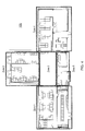
- figure 1 is a schematic representation of a region according to an example.
- the region 100 is shown in plan in the form of a floorplan. Multiple APs 103, 105, 107, 109 are provided at the region 100. Multiple locations, indicated by the squares dispersed over the region 100 are depicted.
- an RF fingerprint is determined by measuring the RSS values from the APs at the region 100. Accordingly, for a given location, such as 111, an RF fingerprint is vector comprising RSS values from the four APs accessible by a device at the location 111.
- Fingerprints for each location at the region 100 are generated to form a fingerprint database for the region 100, and initially the fingerprint database is arranged so that for every AP, there is a list of locations where that AP has been seen (location reports).
- Figure 1 is in the form of a discrete signal strength heat map showing the relative RSS values measured at the locations from API, 105.
- Figure 2 is a schematic representation according to an example, depicting a radio map for the region 100 showing the relative RSS values measured at the locations from API, 105.
- the probability of observing an AP with any RSS value is calculated.
- RSS measurements can have any real value but not all such values are observed.
- the RSS values are discretized into a finite number of bins or ranges. Data binning enables allows a sufficient number of observations for each bin and also reduces the effects of minor observation errors.
- the strongest and weakest RSS values recorded in entire data base are RSS max and RSS min respectively.
- the RSS values of every AP are divided into equally-sized bins for the interval of [ RSS min , RSS max ].
- the number of bins is a pre-defined value, B .
- the RSS values are binned into bins of size 10dB over an interval of [-90dB, -40dB].
- the bin size is assumed big and consequently the number of bins is considered small.
- the number of location reports which fall into every bin is calculated.
- location reports for location 111, 113 fall into bin number 4.
- the entropy weighting described above combines measurements according to the importance of their information about locations.
- Figure 3 is a schematic representation of the region of figures 1 and 2 according to an example.
- Figure 3 is a heat map representing RSS values from an AP, AP2 (201) in the region 100.
- the measurements from API shown in figure 2 are diverse compared with measurements from AP2 shown in figure 3 . Therefore, in an example, API has a higher entropy weight than AP2.
- a UE In online positioning phase, a UE is located at the best matched fingerprint. That is, the current RF fingerprint of a UE can be compared against the fingerprint database in order to determine the best match.
- the fingerprint most closely matching, in terms of Euclidean distance for example, the current fingerprint of the device enables the position of the device to be determined.
- one Entropy weight is assigned to every AP by looking at diversity of RSS values of that AP in the entire floorplan of the building, i.e., one global weight is assigned to each AP.
- this can be further extended by assigning local Entropy weights to every AP in addition to one global Entropy weight.
- two APs may have similar global entropies but in some specific regions in a building, one may be more informative than the other.
- Figure 4 is a schematic representation of a partitioned region according to an example.
- the region 100 is partitioned into five regions, zones 1-5.
- AP3 shown in Figure 5 and AP4 shown in Figure 6 have similar Entropy values across whole building. However they have quite different Entropy values considering only Zone 4 shown in figure 4 .
- AP4 shown in Figure 6 is observed with diverse values in Zone 4 whereas AP3 shown in Figure 5 is observed with almost a flat value across zone 4.
- assigning local Entropy weights to every AP in addition to one global Entropy weight can be implemented in a pre-processing stage as follows:
- the local Entropy weight of each i -th AP is calculated in the same was as described above.
- there are local Entropy weights where is the number of total zones (regions) inside the region.
- five local weights are assigned to every i -th AP, i.e., w i 1 w i 2 w i 3 w i 4 w i 5
- the location of UE is calculated by assigning a global entropy w i to each i -th AP. This provides a rough location estimation.
- the UE's location is recalculated by applying a corresponding local entropy weight w i 2 to each i -th AP. Accordingly, location estimation is refined.
- a user may be located in the boundary of zones.
- the entropy of each AP for merged adjacent regions can be calculated and in the second refinement stage, instead of selecting one region, merged neighbor regions can be considered. That is, if in the rough localization stage a user's location is estimated to be in the boundary of zones (regions), those adjacent zones (where the user is at their boundaries) can be merged to make a bigger zone. Then, the entropy of that combined zone is calculated and can be considered for the location estimation.
- a region can be divided into geographical zones, i.e., static zones.
- the Entropy weights of APs in any of these pre-defined static zones are precalculated in offline phase.
- this can be further improved by performing iterative location estimation in which localized entropy weights are updated based on location estimates. For example, a first iteration localizes a UE as described above based on global entropy weights for the whole region. Subsequently, a localization error can be estimated and a radius r can be defined around the location estimate in which we fall with a 99.9% (or similar) certainty (e.g. 16m).
- New entropy weights for the uncertainty region with radius r (dynamic region) around the current estimate can be generated, and the location estimate updated based on the localized entropy weights. This can be repeated until a solution is converged at. For example, until the radius within which the location falls reaches a predetermined value.
- Figure 7 is a schematic representation of location estimation using dynamic zones according to an example.
- a first location estimate is determined resulting in a radius r1, which provides a region within which a UE is determined to be located with a degree of confidence at or above a predefined value.
- a subsequent iteration in which localized entropy weights are updated based on location estimates results in a second location estimate providing a confidence radius r2.
- a further iteration converges to a location estimate within a region of radius r3, as depicted in figure 7 .
- a region can be divided into geographic zones, e.g., rooms, corridors, etc. Smaller zones result in more accurate location estimates.
- An optimal region size is small enough to refine the location estimates however it should be large enough to observe RSS value diversity since RSS values from a reliable AP in a very small region are stable. That is, RSS values from an AP that are observed in a very small region do not fluctuate a lot, e.g., variations will typically not exceed more than 2-3 dB. Accordingly, in a very small region RSS values from a reliable AP fall into a single bin with a small variance.
- Entropy is provided as a measure of the diversity of signal strength values received from every AP at different locations.
- the entropy value of every AP determines how much unique information that AP provides about a location.
- standard deviation can also be a measure of data diversity. For example, standard deviation can be used to measure the RSS variation from the average (and it depends on the RSS values), whereas entropy measures how diversely RSS values are distributed regardless of the RSS values itself.
- the RSS values from an AP take two values (- rss , rss ) dB with equal probability then the standard deviation is equal to rss which obviously increases when rss changes, but the entropy is constant.
- the measurements from every AP are weighted according to diversity of the RSS measurements from that AP irrespective of RSS values. For example, assume that an AP is observed with a flat strong signal strength in a region and another AP is observed with an almost flat weak signal strength in that region, measurements from both of these APs are non-informative regardless of their RSS values. Therefore, they contribute with similar weights in UE location estimation.
- measurements from all available APs are used since every AP is an input for location estimation and every measurement is weighted according to its importance.
- An available AP can be an AP which is accessible by UE at a location or over all locations in a region.
- a selected set of APs for location estimation (assigning zero weight to unselected APs) can be used in order to reduce localization computational time.
- FIG 8 is a schematic representation of a system according to an example.
- Multiple base station (BS) nodes 801a-c are depicted, which periodically transmit radio signals.
- the radio signal could be from GSM, UMTS or LTE base stations, WiFi, or other radio technologies.
- existing radio infrastructures indoor e.g., indoor Metro Cells, Femto Cells and WiFi nodes can be used. That is, nodes 801a-c can be WiFi access points for example.
- a UE 803 can send and receive data 805 to/from one or more of the access points 801a-c.
- LF uses a radio map of geo-tagged RF measurements, where a map can be a discrete map for multiple locations.
- the most common type of RF measurements used for LF is the received signal strength (RSS) measurements.
- RSS received signal strength
- Small Cell RSS measurements 807 are reported to the network as a part of standard reporting.
- a localization engine or location server 809 that stores floor plan maps, radio maps, and locations of BSs and landmarks (if available) is provided using a database 811 for example.
- the localization server 809 can be a part of a core network (network-based localization) of a wireless telecommunication system 810 and/or the node (terminal-based localization) of such a system.
- the localization engine 809 can be located at a cloud server which can be centrally managed by authorized centers, or locally by the building managers or enterprise owners.
- engine 809 calculates UE's 803 location by comparing UE's real-time RF measurements 807 with prerecorded entries in the radio map in database 811.
- the location data 813 can be provided back to the UE 803 via one of the access points 801a-c, or using another network node (not shown).
- the UE location data 813 can be provided to an external authorized center or device 815 for the purposes of public safety for example.
Landscapes
- Physics & Mathematics (AREA)
- Engineering & Computer Science (AREA)
- General Physics & Mathematics (AREA)
- Radar, Positioning & Navigation (AREA)
- Remote Sensing (AREA)
- Position Fixing By Use Of Radio Waves (AREA)
- Mobile Radio Communication Systems (AREA)
Abstract
Description
- Aspects relate, in general, to a method for use in determining the location of user equipment within a region a location server and a computer program product.
- Location determination of mobile devices in indoor environments has attracted significant attention due to its numerous applications in areas of mobile networking, emergency, defense, retail shopping, e-health, social networking, and so on. Some examples of location-based services are locating people and navigating them to their destinations in shopping malls, airports, hospitals, and museums, recommending nearest services such as ATMs, retail stores, restaurants and social events, location-based advertising, finding and tracking stolen or lost objects, monitoring human activities, and so on.
- Location Fingerprinting (LF) is a localization technique for many location aware applications. The LF technique uses a radio frequency (RF) fingerprint database (typically called a radio map) of the field of interest. The radio map contains RF measurements from multiple base stations at multiple known locations (fingerprints). A device, such as user equipment (UE) at the location in question measures the radio signals from multiple base stations; these radio signals are then compared against the fingerprints which are pre-recorded in a radio map to identify the device's location. The device is located at the fingerprint that best matches its RF measurements.
- According to an example, there is provided a method, for use in determining the location of user equipment within a region, the method comprising generating a measure of the diversity of received signal strength values from multiple access points accessible by user equipment at the region using an entropy value calculated using a probability measure of observing a discretised RSS value for an access point, and generating an entropy weight measure for respective ones of the access points using the measure of diversity. The method can further comprise, at multiple predefined locations within the region, determining radio signal strength measurements from respective ones of the multiple access points, and discretising the radio signal strength measurements by binning the measurements into respective selected ones of a predefined number of bins over an interval defined by maximum and minimum observed radio signal strength measurements over all predefined locations for the multiple access points. Each bin represents a range of radio signal strength measurements. Accordingly, the entire range is defined by the interval between the maximum to minimum RSS value, from which a series of smaller intervals is provided, up to B in number (i.e. the number of bins). A measure of the probability of observing respective ones of the bins by every access point can be calculated. The entropy value, E, for an access point, i, can be generated by calculating:


- According to an example, there is provided a location server in a wireless telecommunication network, the location server being operable to receive an RF fingerprint from UE in a region, perform a weighted comparison of the RF fingerprint against a set of pre-existing RF fingerprints for the region using an entropy weight measure providing a measure of the diversity of received signal strength values from multiple access points accessible by the UE at the region, and determine the location of the UE within the region. The region can be divided into multiple zones, and the location server can determine a zone of the region within which the UE is located using a global entropy measure for the region, and determine the location of the UE within the zone using a local entropy weight associated with the zone in question. The location server can receive radio signal strength measurements observed at respective multiple predefined locations within the region from respective ones of multiple access points accessible at the region, and discretise the radio signal strength measurements by binning the measurements into respective selected ones of a predefined number of bins over an interval defined by maximum and minimum observed radio signal strength measurements over all predefined locations for the multiple access points.
- The location server can calculate a modified Euclidean distance in signal space between the RF fingerprint from the UE and every j-th fingerprint from the set of pre-existing RF fingerprints for the region according to:


- According to an example, there is provided a computer program product, comprising a computer usable medium having computer readable program code embodied therein, said computer readable program code adapted to be executed to implement a method for use in determining the location of user equipment within a region as provided herein.
- Embodiments will now be described, by way of example only, with reference to the accompanying drawings, in which:
-
Figure 1 is a schematic representation of a region according to an example; -
Figure 2 is a schematic representation according to an example, depicting a radio map for the region; -
Figure 3 is a schematic representation of the region offigures 1 and2 according to an example; -
Figure 4 is a schematic representation of a partitioned region according to an example; -
Figure 5 is a schematic representation of a partitioned region according to an example; -
Figure 6 is a schematic representation of a partitioned region according to an example; -
Figure 7 is a schematic representation of location estimation using dynamic zones according to an example; and -
Figure 8 is a schematic representation of a system according to an example. - Example embodiments are described below in sufficient detail to enable those of ordinary skill in the art to embody and implement the systems and processes herein described. It is important to understand that embodiments can be provided in many alternate forms and should not be construed as limited to the examples set forth herein.
- Accordingly, while embodiments can be modified in various ways and take on various alternative forms, specific embodiments thereof are shown in the drawings and described in detail below as examples. There is no intent to limit to the particular forms disclosed. On the contrary, all modifications, equivalents, and alternatives falling within the scope of the appended claims should be included. Elements of the example embodiments are consistently denoted by the same reference numerals throughout the drawings and detailed description where appropriate.
- The terminology used herein to describe embodiments is not intended to limit the scope. The articles "a," "an," and "the" are singular in that they have a single referent, however the use of the singular form in the present document should not preclude the presence of more than one referent. In other words, elements referred to in the singular can number one or more, unless the context clearly indicates otherwise. It will be further understood that the terms "comprises," "comprising," "includes," and/or "including," when used herein, specify the presence of stated features, items, steps, operations, elements, and/or components, but do not preclude the presence or addition of one or more other features, items, steps, operations, elements, components, and/or groups thereof.
- Unless otherwise defined, all terms (including technical and scientific terms) used herein are to be interpreted as is customary in the art. It will be further understood that terms in common usage should also be interpreted as is customary in the relevant art and not in an idealized or overly formal sense unless expressly so defined herein.
- In a location fingerprinting system, each RF Fingerprint is a unique signature of the location where it is recorded. Every fingerprint captures multipath characteristics of its location and hence the LF technique mitigates non line-of-sight (NLoS) effects and can provide accurate positioning information. LF provides meter-level location accuracy given a reliable fingerprint database. A reliable RF fingerprint is spatially unique and temporarily stable.
- Location fingerprinting (LF) techniques infer user equipment (UE)'s location by comparing the UE's RF measurements against RF fingerprints which are pre-recorded in a radio map. Fingerprints are collected in multiple known locations (reference locations) in an offline phase. Every fingerprint is a geo-tagged vector of RF measurements from k observed access points (APs). In an online phase, a UE at the location in question measures the radio signals from l available APs and reports the online measurement vector to a location server for example. The location server locates the UE at the fingerprint that best matches its current RF measurement vector.
- To find the best matching fingerprint, the most widely used technique is based on minimizing Euclidean signal distance. Typically, assuming that N common APs are observed by a UE and are measured at j-th reference location, the Euclidean distance in signal space between the UE and j-th fingerprint can be calculated as


- In common LF techniques, measurements from every AP that are accessible to the UE in a given region are given the same confidence in UE's location estimation. More enhanced LF techniques apply different weights to every measurement according to its signal strength, temporal- stability or measurement accuracy. For example, in some approaches, an AP that is seen with stronger signal strength contributes with a relatively higher weight in a location estimation process. However, signal strength is not a comprehensive metric to evaluate how much information every measurement contains about UE location. For example, many locations in an open space office can be in line-of-sight view of an AP and hence a similar high signal strength from that AP is measured at many locations. That is, an access point that contributes to an RF fingerprint at a given location, may also contribute to RF fingerprints at multiple other locations.
- Another example is that an AP which is located outside the building (field or region of interest for localization) can be detected with an almost flat low radio signal strength (RSS) value in many locations inside the building. None of these flat high or flat low measurement values can specify a unique location. As a result, no existing approach shows any significant improvements in location estimation and no existing approach considers how much unique information an AP provides about a location.
- According to an example, an offline analytic approach to quantify the uniqueness and reliability of fingerprints is provided. More specifically, measurements from APs within a region contribute with different weights in estimating a device's location, where the weights are applied to each measurement according to its spatial uniqueness. In an example, a measure of the entropy as a metric of spatial uniqueness of measurements is used. For example, Shannon's Entropy can be used as a metric of spatial uniqueness of measurements. This can significantly improve the accuracy of LF over existing approaches.
- Due to placement of APs and the structure of a building for example, some APs may be detected with similar RSS levels in some regions inside the building and some other APs may be scanned with more diverse RSS values in different regions in the building. Insight into how much information every AP provides about locations at different regions of the building can be gained by looking at a signal strength heatmap in an offline pre-processing stage. An entropy measure, such as Shannon's Entropy for example, can be used as a metric of RSS measurement diversity. Accordingly, in an example, measurements from different APs get different weights for the purposes of location estimation. Such a method is broadly applicable to signals from wireless networks such as WiFi, GSM, UMTS, LTE, and so on.
- According to an example, in an offline phase a radio map of a region of interest containing prerecorded fingerprints at multiple known locations can be generated. The radio map can be collected in an offline phase either manually or using crowd sourcing approaches for example in which radio measurements from various locations at the region can be provided by multiple users in order to build up a fingerprint database for the region.
- A fingerprint is a vector of RF measurements from multiple observed APs. In an example, the APs are those which are accessible to UE at the region. Accordingly, APs that contribute to a fingerprint are typically those that UE may be able to connect with or otherwise detect. The most common type of RF measurements used for LF are received signal strength (RSS) measurements. The radio signal can be from WiFi access points, GSM, UMTS or LTE base stations, or other RF-based networks. To avoid extra deployment costs and effort, already existing radio infrastructures indoor, e.g., WiFi and Small Cells can be exploited.
- In general, the collection of RF fingerprints at multiple locations at a region using UE is well-known, and will not be described in any further detail herein. Multiple RF fingerprints are provided can be a fingerprint database, or more generally a list or catalogue. For example, at a given location, multiple RSS measurements are taken, measured or sampled to provide a fingerprint for that location in the form of a geo-tagged vector of RF measurements from the multiple observed access points, as described above.
- After collecting fingerprints, the spatial uniqueness of measurements from every AP is quantified in an offline pre-analytical process. In this connection,
figure 1 is a schematic representation of a region according to an example. Theregion 100 is shown in plan in the form of a floorplan.Multiple APs region 100. Multiple locations, indicated by the squares dispersed over theregion 100 are depicted. At each location, an RF fingerprint is determined by measuring the RSS values from the APs at theregion 100. Accordingly, for a given location, such as 111, an RF fingerprint is vector comprising RSS values from the four APs accessible by a device at the location 111. Fingerprints for each location at theregion 100 are generated to form a fingerprint database for theregion 100, and initially the fingerprint database is arranged so that for every AP, there is a list of locations where that AP has been seen (location reports).Figure 1 is in the form of a discrete signal strength heat map showing the relative RSS values measured at the locations from API, 105.Figure 2 is a schematic representation according to an example, depicting a radio map for theregion 100 showing the relative RSS values measured at the locations from API, 105. - According to an example, the probability of observing an AP with any RSS value is calculated. RSS measurements can have any real value but not all such values are observed. In order to be able to calculate the probability, the RSS values are discretized into a finite number of bins or ranges. Data binning enables allows a sufficient number of observations for each bin and also reduces the effects of minor observation errors.
- Assume that the strongest and weakest RSS values recorded in entire data base are RSSmax and RSSmin respectively. The RSS values of every AP are divided into equally-sized bins for the interval of [RSSmin, RSSmax ]. In an example, the number of bins is a pre-defined value, B. For example, for the region of
figure 1 , the RSS values are binned into bins of size 10dB over an interval of [-90dB, -40dB]. For simplicity of description, in this example, the bin size is assumed big and consequently the number of bins is considered small. - For every AP, the number of location reports which fall into every bin is calculated. In the example of
figure 1 , location reports for location 111, 113 fall intobin number 4. The probability of observing each bin by every AP is then calculated. More specifically, the probability of observing b- th bin from i- th AP is:
- An entropy-based metric which measures the diversity of RSS values from each AP is calculated. Accordingly, the Entropy of i-th AP is:

According to an example, entropy is used as a measure of diversity, meaning that the larger the entropy of an AP the more information that AP provides about location. Conversely, the smaller the entropy value of an AP the less information that AP provides about location. Therefore, according to an example, an AP with a larger measure of Entropy contributes with a higher weight in location estimation. - Thus, the Entropy-weight of every i-th AP is defined as:


- The entropy weighting described above combines measurements according to the importance of their information about locations.
-
Figure 3 is a schematic representation of the region offigures 1 and2 according to an example.Figure 3 is a heat map representing RSS values from an AP, AP2 (201) in theregion 100. The measurements from API shown infigure 2 are diverse compared with measurements from AP2 shown infigure 3 . Therefore, in an example, API has a higher entropy weight than AP2. - In online positioning phase, a UE is located at the best matched fingerprint. That is, the current RF fingerprint of a UE can be compared against the fingerprint database in order to determine the best match. The fingerprint most closely matching, in terms of Euclidean distance for example, the current fingerprint of the device enables the position of the device to be determined.
- According to an example, in order to find the best matching entry in a database of existing RF fingerprints for multiple locations in a region, a modified Euclidean distance is calculated in signal space between a UE and every j-th fingerprint according to:

- In the above example, one Entropy weight is assigned to every AP by looking at diversity of RSS values of that AP in the entire floorplan of the building, i.e., one global weight is assigned to each AP.
- According to an example, this can be further extended by assigning local Entropy weights to every AP in addition to one global Entropy weight. For example, two APs may have similar global entropies but in some specific regions in a building, one may be more informative than the other.
-
Figure 4 is a schematic representation of a partitioned region according to an example. In the example offigure 4 , theregion 100 is partitioned into five regions, zones 1-5. AP3 shown inFigure 5 and AP4 shown inFigure 6 have similar Entropy values across whole building. However they have quite different Entropy values considering onlyZone 4 shown infigure 4 . AP4 shown inFigure 6 is observed with diverse values inZone 4 whereas AP3 shown inFigure 5 is observed with almost a flat value acrosszone 4. - According to an example, assigning local Entropy weights to every AP in addition to one global Entropy weight can be implemented in a pre-processing stage as follows:
- As depicted in
figure 4 , a region is divided into geographic regions. For example an enterprise building can be divided into workspace areas, open space areas, corridors, laboratories, adjacent rooms, and so on. This can be performed manually, or automatically if an existing plan of a region exists which includes zonal information to demarcate different areas of the region. - For every region, the local Entropy weight of each i-th AP is calculated in the same was as described above. For every AP, there are local Entropy weights, where is the number of total zones (regions) inside the region. In the example of
figure 4 , five local weights are assigned to every i-th AP, i.e.,
- In an online positioning phase, firstly the location of UE is calculated by assigning a global entropy wi to each i-th AP. This provides a rough location estimation. In next stage, knowing the zone of the region where the user is located (e.g., zone z), the UE's location is recalculated by applying a corresponding local entropy
weight 
- In the rough localization stage, a user may be located in the boundary of zones. To resolve such an edge problem, the entropy of each AP for merged adjacent regions can be calculated and in the second refinement stage, instead of selecting one region, merged neighbor regions can be considered. That is, if in the rough localization stage a user's location is estimated to be in the boundary of zones (regions), those adjacent zones (where the user is at their boundaries) can be merged to make a bigger zone. Then, the entropy of that combined zone is calculated and can be considered for the location estimation.
- Thus, to calculate the local Entropy weights, a region can be divided into geographical zones, i.e., static zones. The Entropy weights of APs in any of these pre-defined static zones are precalculated in offline phase. In an example, this can be further improved by performing iterative location estimation in which localized entropy weights are updated based on location estimates. For example, a first iteration localizes a UE as described above based on global entropy weights for the whole region. Subsequently, a localization error can be estimated and a radius r can be defined around the location estimate in which we fall with a 99.9% (or similar) certainty (e.g. 16m).
- New entropy weights for the uncertainty region with radius r (dynamic region) around the current estimate can be generated, and the location estimate updated based on the localized entropy weights. This can be repeated until a solution is converged at. For example, until the radius within which the location falls reaches a predetermined value.
-
Figure 7 is a schematic representation of location estimation using dynamic zones according to an example. In aregion 100, a first location estimate is determined resulting in a radius r1, which provides a region within which a UE is determined to be located with a degree of confidence at or above a predefined value. A subsequent iteration in which localized entropy weights are updated based on location estimates results in a second location estimate providing a confidence radius r2. A further iteration converges to a location estimate within a region of radius r3, as depicted infigure 7 . - As described, a region can be divided into geographic zones, e.g., rooms, corridors, etc. Smaller zones result in more accurate location estimates. An optimal region size is small enough to refine the location estimates however it should be large enough to observe RSS value diversity since RSS values from a reliable AP in a very small region are stable. That is, RSS values from an AP that are observed in a very small region do not fluctuate a lot, e.g., variations will typically not exceed more than 2-3 dB. Accordingly, in a very small region RSS values from a reliable AP fall into a single bin with a small variance.
- Entropy is provided as a measure of the diversity of signal strength values received from every AP at different locations. The entropy value of every AP determines how much unique information that AP provides about a location. In an example, standard deviation can also be a measure of data diversity. For example, standard deviation can be used to measure the RSS variation from the average (and it depends on the RSS values), whereas entropy measures how diversely RSS values are distributed regardless of the RSS values itself.
- For example, if the RSS values from an AP take two values (-rss,rss) dB with equal probability then the standard deviation is equal to rss which obviously increases when rss changes, but the entropy is constant. In an example, the measurements from every AP are weighted according to diversity of the RSS measurements from that AP irrespective of RSS values. For example, assume that an AP is observed with a flat strong signal strength in a region and another AP is observed with an almost flat weak signal strength in that region, measurements from both of these APs are non-informative regardless of their RSS values. Therefore, they contribute with similar weights in UE location estimation.
- In an example, measurements from all available APs are used since every AP is an input for location estimation and every measurement is weighted according to its importance. An available AP can be an AP which is accessible by UE at a location or over all locations in a region. In an example, a selected set of APs for location estimation (assigning zero weight to unselected APs) can be used in order to reduce localization computational time.
-
Figure 8 is a schematic representation of a system according to an example. Multiple base station (BS) nodes 801a-c are depicted, which periodically transmit radio signals. The radio signal could be from GSM, UMTS or LTE base stations, WiFi, or other radio technologies. To avoid extra deployment costs and effort, existing radio infrastructures indoor, e.g., indoor Metro Cells, Femto Cells and WiFi nodes can be used. That is, nodes 801a-c can be WiFi access points for example. AUE 803 can send and receivedata 805 to/from one or more of the access points 801a-c. - As described above, LF uses a radio map of geo-tagged RF measurements, where a map can be a discrete map for multiple locations. The most common type of RF measurements used for LF is the received signal strength (RSS) measurements. Small
Cell RSS measurements 807 are reported to the network as a part of standard reporting. - A localization engine or
location server 809 that stores floor plan maps, radio maps, and locations of BSs and landmarks (if available) is provided using adatabase 811 for example. Thelocalization server 809 can be a part of a core network (network-based localization) of awireless telecommunication system 810 and/or the node (terminal-based localization) of such a system. Thelocalization engine 809 can be located at a cloud server which can be centrally managed by authorized centers, or locally by the building managers or enterprise owners. - In an example,
engine 809 calculates UE's 803 location by comparing UE's real-time RF measurements 807 with prerecorded entries in the radio map indatabase 811. Thelocation data 813 can be provided back to theUE 803 via one of the access points 801a-c, or using another network node (not shown). TheUE location data 813 can be provided to an external authorized center ordevice 815 for the purposes of public safety for example. - The present inventions can be embodied in other specific apparatus and/or methods. The described embodiments are to be considered in all respects as illustrative and not restrictive. In particular, the scope of the invention is indicated by the appended claims rather than by the description and figures herein. All changes that come within the meaning and range of equivalency of the claims are to be embraced within their scope.
Claims (15)
- A method, for use in determining the location of user equipment within a region, the method comprising:generating a measure of the diversity of received signal strength values from multiple access points accessible by user equipment at the region using an entropy value calculated using a probability measure of observing a discretised RSS value for an access point; andgenerating an entropy weight measure for respective ones of the access points using the measure of diversity.
- A method as claimed in claim 1, further comprising:at multiple predefined locations within the region, determining radio signal strength measurements from respective ones of the multiple access points; anddiscretising the radio signal strength measurements by binning the measurements into respective selected ones of a predefined number of bins over an interval defined by maximum and minimum observed radio signal strength measurements over all predefined locations for the multiple access points.
- A method as claimed in claim 2, wherein each bin represents a range of radio signal strength measurements.
- A method as claimed in claim 2 or 3, further comprising:calculating a measure of the probability of observing respective ones of the bins by every access point.
- A method as claimed in 4, further comprising:generating the entropy value, E, for an access point, i, by calculating:

- A method as claimed in claim 5, further comprising:generating an entropy weight measure for an access point by calculating:


- A method as claimed in any preceding claim, further comprising:dividing the region into zones; andassigning respective local entropy weights to each one of the multiple access points.
- A method as claimed in claim 7, further comprising;
determining the zone within which the user equipment is located; and
calculating the position of the user equipment in the zone using a local entropy weight associated with the zone in question. - A method as claimed in any preceding claim, further comprising:determining, at the user equipment, the received signal strength from respective ones of the multiple access points to form a location fingerprint for the user equipment at a location within the region; andcomparing the location fingerprint with predetermined location fingerprints comprising respective sets of measurements of received signal strength from the multiple access points at respective multiple predefined locations within the region, wherein the entropy weight is used to modify the contribution of respective ones of the access points to a determination of user equipment position relative to the multiple access points.
- A location server in a wireless telecommunication network, the location server being operable to:receive an RF fingerprint from UE in a region;perform a weighted comparison of the RF fingerprint against a set of pre-existing RF fingerprints for the region using an entropy weight measure providing a measure of the diversity of received signal strength values from multiple access points accessible by the UE at the region; anddetermine the location of the UE within the region.
- A location server as claimed in claim 10, wherein the region is divided into multiple zones, the location server further operable to:determine a zone of the region within which the UE is located using a global entropy measure for the region; anddetermine the location of the UE within the zone using a local entropy weight associated with the zone in question.
- A location server as claimed in claim 10 or 11, the location server being further operable to:receive radio signal strength measurements observed at respective multiple predefined locations within the region from respective ones of multiple access points accessible at the region; anddiscretise the radio signal strength measurements by binning the measurements into respective selected ones of a predefined number of bins over an interval defined by maximum and minimum observed radio signal strength measurements over all predefined locations for the multiple access points.
- A location server as claimed in any of claims 10 to 12, wherein the location server is operable to calculate a modified Euclidean distance in signal space between the RF fingerprint from the UE and every j-th fingerprint from the set of pre-existing RF fingerprints for the region according to:

- A location server as claimed in claim 13, wherein the location server is operable to generate an entropy weight measure for an access point by calculating:


- A computer program product, comprising a computer usable medium having computer readable program code embodied therein, said computer readable program code adapted to be executed to implement a method for use in determining the location of user equipment within a region as claimed in any of claims 1 to 9.
Priority Applications (1)
| Application Number | Priority Date | Filing Date | Title |
|---|---|---|---|
| EP15305777.3A EP3096155B1 (en) | 2015-05-22 | 2015-05-22 | A method for use in determining the location of user equipment within a region, a location server and a computer program product |
Applications Claiming Priority (1)
| Application Number | Priority Date | Filing Date | Title |
|---|---|---|---|
| EP15305777.3A EP3096155B1 (en) | 2015-05-22 | 2015-05-22 | A method for use in determining the location of user equipment within a region, a location server and a computer program product |
Publications (2)
| Publication Number | Publication Date |
|---|---|
| EP3096155A1 true EP3096155A1 (en) | 2016-11-23 |
| EP3096155B1 EP3096155B1 (en) | 2020-12-02 |
Family
ID=53396400
Family Applications (1)
| Application Number | Title | Priority Date | Filing Date |
|---|---|---|---|
| EP15305777.3A Not-in-force EP3096155B1 (en) | 2015-05-22 | 2015-05-22 | A method for use in determining the location of user equipment within a region, a location server and a computer program product |
Country Status (1)
| Country | Link |
|---|---|
| EP (1) | EP3096155B1 (en) |
Cited By (4)
| Publication number | Priority date | Publication date | Assignee | Title |
|---|---|---|---|---|
| CN108712317A (en) * | 2018-03-28 | 2018-10-26 | 北京大学 | A kind of Urban population space-time dynamic cognitive method and system based on mobile social networking |
| CN109874112A (en) * | 2017-12-05 | 2019-06-11 | 华为技术有限公司 | A kind of method and terminal of positioning |
| US10820152B2 (en) | 2017-08-04 | 2020-10-27 | International Business Machines Corporation | Device diversity correction method for RSS-based precise location tracking |
| CN112566055A (en) * | 2020-11-27 | 2021-03-26 | 巢湖学院 | Indoor positioning algorithm based on radio frequency fingerprint matching |
Families Citing this family (1)
| Publication number | Priority date | Publication date | Assignee | Title |
|---|---|---|---|---|
| US11805389B2 (en) * | 2020-10-27 | 2023-10-31 | International Business Machines Corporation | Evaluation of device placement |
Citations (1)
| Publication number | Priority date | Publication date | Assignee | Title |
|---|---|---|---|---|
| US20140171118A1 (en) * | 2012-12-14 | 2014-06-19 | Apple Inc. | Location fingerprinting |
-
2015
- 2015-05-22 EP EP15305777.3A patent/EP3096155B1/en not_active Not-in-force
Patent Citations (1)
| Publication number | Priority date | Publication date | Assignee | Title |
|---|---|---|---|---|
| US20140171118A1 (en) * | 2012-12-14 | 2014-06-19 | Apple Inc. | Location fingerprinting |
Non-Patent Citations (3)
| Title |
|---|
| LING PEI ET AL: "The evaluation of WiFi positioning in a Bluetooth and WiFi coexistence environment", UBIQUITOUS POSITIONING, INDOOR NAVIGATION, AND LOCATION BASED SERVICE (UPINLBS), 2012, IEEE, 3 October 2012 (2012-10-03), pages 1 - 6, XP032307942, ISBN: 978-1-4673-1908-9, DOI: 10.1109/UPINLBS.2012.6409768 * |
| MOHTASHEMI BRIAN ET AL: "Source-Observation Weighted Fingerprinting for machine learning based localization", 2014 WIRELESS TELECOMMUNICATIONS SYMPOSIUM, IEEE, 9 April 2014 (2014-04-09), pages 1 - 6, XP032606525, DOI: 10.1109/WTS.2014.6835033 * |
| ROOS T ET AL: "A probabilistic approach to WLAN user location estimation", INTERNATIONAL JOURNAL OF WIRELESS INFORMATION NETWORKS, PLENUM PRESS, NEW YORK, NY, US, vol. 9, no. 3, 1 July 2002 (2002-07-01), pages 155 - 164, XP002303670, ISSN: 1068-9605, DOI: 10.1023/A:1016003126882 * |
Cited By (7)
| Publication number | Priority date | Publication date | Assignee | Title |
|---|---|---|---|---|
| US10820152B2 (en) | 2017-08-04 | 2020-10-27 | International Business Machines Corporation | Device diversity correction method for RSS-based precise location tracking |
| CN109874112A (en) * | 2017-12-05 | 2019-06-11 | 华为技术有限公司 | A kind of method and terminal of positioning |
| CN109874112B (en) * | 2017-12-05 | 2021-06-15 | 华为技术有限公司 | A positioning method and terminal |
| CN108712317A (en) * | 2018-03-28 | 2018-10-26 | 北京大学 | A kind of Urban population space-time dynamic cognitive method and system based on mobile social networking |
| CN108712317B (en) * | 2018-03-28 | 2020-12-22 | 北京大学 | A method and system for spatiotemporal dynamic perception of urban crowd based on mobile social network |
| CN112566055A (en) * | 2020-11-27 | 2021-03-26 | 巢湖学院 | Indoor positioning algorithm based on radio frequency fingerprint matching |
| CN112566055B (en) * | 2020-11-27 | 2022-06-10 | 巢湖学院 | Indoor positioning algorithm based on radio frequency fingerprint matching |
Also Published As
| Publication number | Publication date |
|---|---|
| EP3096155B1 (en) | 2020-12-02 |
Similar Documents
| Publication | Publication Date | Title |
|---|---|---|
| Yim | Introducing a decision tree-based indoor positioning technique | |
| Lim et al. | Zero-configuration, robust indoor localization: Theory and experimentation | |
| EP3108706B1 (en) | Localization of a wireless user equipmentdevice in a target zone | |
| US9426613B2 (en) | System and method for estimating positioning error within a WLAN-based positioning system | |
| Lee et al. | Voronoi tessellation based interpolation method for Wi-Fi radio map construction | |
| He et al. | Fusing noisy fingerprints with distance bounds for indoor localization | |
| US20140197990A1 (en) | Method for enhancing location identity through incorporation of shorter range communication and sensing (nearlocate) | |
| US20120063427A1 (en) | Crowd formation based on wireless context information | |
| EP3096155B1 (en) | A method for use in determining the location of user equipment within a region, a location server and a computer program product | |
| EP3001215A1 (en) | Method for determining the relative position of user equipment in a wireless telecommunication network, a node and a computer program product | |
| Laitinen et al. | Access point significance measures in WLAN-based location | |
| Liu et al. | Mobile localization based on received signal strength and Pearson's correlation coefficient | |
| Trogh et al. | Advanced real-time indoor tracking based on the viterbi algorithm and semantic data | |
| Luo et al. | Accuracy-aware wireless indoor localization: Feasibility and applications | |
| He et al. | Towards crowdsourced signal map construction via implicit interaction of IoT devices | |
| Morales et al. | Mitigating anomalous measurements for indoor wireless local area network positioning | |
| Bai et al. | A new approach for indoor customer tracking based on a single Wi-Fi connection | |
| Meneses et al. | Radio maps for fingerprinting in indoor positioning | |
| Dashti et al. | Detecting co-located mobile users | |
| Yu et al. | An adaptive model recognition and construction method for RSSI fingerprint-based localization | |
| Xu et al. | Variance-based fingerprint distance adjustment algorithm for indoor localization | |
| Brković et al. | Multidimensional optimization of signal space distance parameters in WLAN positioning | |
| Nam | Localization of access points based on signal strength measured by a mobile user node | |
| Lau et al. | Novel indoor localisation using an unsupervised Wi-Fi signal clustering method | |
| Mustaquim et al. | A resource utilizing approach towards implementing indoor localization using Wi-Fi network |
Legal Events
| Date | Code | Title | Description |
|---|---|---|---|
| PUAI | Public reference made under article 153(3) epc to a published international application that has entered the european phase |
Free format text: ORIGINAL CODE: 0009012 |
|
| AK | Designated contracting states |
Kind code of ref document: A1 Designated state(s): AL AT BE BG CH CY CZ DE DK EE ES FI FR GB GR HR HU IE IS IT LI LT LU LV MC MK MT NL NO PL PT RO RS SE SI SK SM TR |
|
| AX | Request for extension of the european patent |
Extension state: BA ME |
|
| STAA | Information on the status of an ep patent application or granted ep patent |
Free format text: STATUS: REQUEST FOR EXAMINATION WAS MADE |
|
| 17P | Request for examination filed |
Effective date: 20170523 |
|
| RBV | Designated contracting states (corrected) |
Designated state(s): AL AT BE BG CH CY CZ DE DK EE ES FI FR GB GR HR HU IE IS IT LI LT LU LV MC MK MT NL NO PL PT RO RS SE SI SK SM TR |
|
| RAP1 | Party data changed (applicant data changed or rights of an application transferred) |
Owner name: ALCATEL LUCENT |
|
| GRAP | Despatch of communication of intention to grant a patent |
Free format text: ORIGINAL CODE: EPIDOSNIGR1 |
|
| STAA | Information on the status of an ep patent application or granted ep patent |
Free format text: STATUS: GRANT OF PATENT IS INTENDED |
|
| INTG | Intention to grant announced |
Effective date: 20200619 |
|
| GRAS | Grant fee paid |
Free format text: ORIGINAL CODE: EPIDOSNIGR3 |
|
| GRAA | (expected) grant |
Free format text: ORIGINAL CODE: 0009210 |
|
| STAA | Information on the status of an ep patent application or granted ep patent |
Free format text: STATUS: THE PATENT HAS BEEN GRANTED |
|
| AK | Designated contracting states |
Kind code of ref document: B1 Designated state(s): AL AT BE BG CH CY CZ DE DK EE ES FI FR GB GR HR HU IE IS IT LI LT LU LV MC MK MT NL NO PL PT RO RS SE SI SK SM TR |
|
| REG | Reference to a national code |
Ref country code: GB Ref legal event code: FG4D |
|
| REG | Reference to a national code |
Ref country code: AT Ref legal event code: REF Ref document number: 1341528 Country of ref document: AT Kind code of ref document: T Effective date: 20201215 Ref country code: CH Ref legal event code: EP |
|
| REG | Reference to a national code |
Ref country code: DE Ref legal event code: R096 Ref document number: 602015062835 Country of ref document: DE |
|
| REG | Reference to a national code |
Ref country code: IE Ref legal event code: FG4D |
|
| PG25 | Lapsed in a contracting state [announced via postgrant information from national office to epo] |
Ref country code: NO Free format text: LAPSE BECAUSE OF FAILURE TO SUBMIT A TRANSLATION OF THE DESCRIPTION OR TO PAY THE FEE WITHIN THE PRESCRIBED TIME-LIMIT Effective date: 20210302 Ref country code: RS Free format text: LAPSE BECAUSE OF FAILURE TO SUBMIT A TRANSLATION OF THE DESCRIPTION OR TO PAY THE FEE WITHIN THE PRESCRIBED TIME-LIMIT Effective date: 20201202 Ref country code: FI Free format text: LAPSE BECAUSE OF FAILURE TO SUBMIT A TRANSLATION OF THE DESCRIPTION OR TO PAY THE FEE WITHIN THE PRESCRIBED TIME-LIMIT Effective date: 20201202 Ref country code: GR Free format text: LAPSE BECAUSE OF FAILURE TO SUBMIT A TRANSLATION OF THE DESCRIPTION OR TO PAY THE FEE WITHIN THE PRESCRIBED TIME-LIMIT Effective date: 20210303 |
|
| REG | Reference to a national code |
Ref country code: NL Ref legal event code: MP Effective date: 20201202 |
|
| REG | Reference to a national code |
Ref country code: AT Ref legal event code: MK05 Ref document number: 1341528 Country of ref document: AT Kind code of ref document: T Effective date: 20201202 |
|
| PG25 | Lapsed in a contracting state [announced via postgrant information from national office to epo] |
Ref country code: LV Free format text: LAPSE BECAUSE OF FAILURE TO SUBMIT A TRANSLATION OF THE DESCRIPTION OR TO PAY THE FEE WITHIN THE PRESCRIBED TIME-LIMIT Effective date: 20201202 Ref country code: PL Free format text: LAPSE BECAUSE OF FAILURE TO SUBMIT A TRANSLATION OF THE DESCRIPTION OR TO PAY THE FEE WITHIN THE PRESCRIBED TIME-LIMIT Effective date: 20201202 Ref country code: SE Free format text: LAPSE BECAUSE OF FAILURE TO SUBMIT A TRANSLATION OF THE DESCRIPTION OR TO PAY THE FEE WITHIN THE PRESCRIBED TIME-LIMIT Effective date: 20201202 Ref country code: BG Free format text: LAPSE BECAUSE OF FAILURE TO SUBMIT A TRANSLATION OF THE DESCRIPTION OR TO PAY THE FEE WITHIN THE PRESCRIBED TIME-LIMIT Effective date: 20210302 |
|
| PG25 | Lapsed in a contracting state [announced via postgrant information from national office to epo] |
Ref country code: NL Free format text: LAPSE BECAUSE OF FAILURE TO SUBMIT A TRANSLATION OF THE DESCRIPTION OR TO PAY THE FEE WITHIN THE PRESCRIBED TIME-LIMIT Effective date: 20201202 Ref country code: HR Free format text: LAPSE BECAUSE OF FAILURE TO SUBMIT A TRANSLATION OF THE DESCRIPTION OR TO PAY THE FEE WITHIN THE PRESCRIBED TIME-LIMIT Effective date: 20201202 |
|
| REG | Reference to a national code |
Ref country code: LT Ref legal event code: MG9D |
|
| PG25 | Lapsed in a contracting state [announced via postgrant information from national office to epo] |
Ref country code: CZ Free format text: LAPSE BECAUSE OF FAILURE TO SUBMIT A TRANSLATION OF THE DESCRIPTION OR TO PAY THE FEE WITHIN THE PRESCRIBED TIME-LIMIT Effective date: 20201202 Ref country code: EE Free format text: LAPSE BECAUSE OF FAILURE TO SUBMIT A TRANSLATION OF THE DESCRIPTION OR TO PAY THE FEE WITHIN THE PRESCRIBED TIME-LIMIT Effective date: 20201202 Ref country code: SM Free format text: LAPSE BECAUSE OF FAILURE TO SUBMIT A TRANSLATION OF THE DESCRIPTION OR TO PAY THE FEE WITHIN THE PRESCRIBED TIME-LIMIT Effective date: 20201202 Ref country code: LT Free format text: LAPSE BECAUSE OF FAILURE TO SUBMIT A TRANSLATION OF THE DESCRIPTION OR TO PAY THE FEE WITHIN THE PRESCRIBED TIME-LIMIT Effective date: 20201202 Ref country code: SK Free format text: LAPSE BECAUSE OF FAILURE TO SUBMIT A TRANSLATION OF THE DESCRIPTION OR TO PAY THE FEE WITHIN THE PRESCRIBED TIME-LIMIT Effective date: 20201202 Ref country code: PT Free format text: LAPSE BECAUSE OF FAILURE TO SUBMIT A TRANSLATION OF THE DESCRIPTION OR TO PAY THE FEE WITHIN THE PRESCRIBED TIME-LIMIT Effective date: 20210405 Ref country code: RO Free format text: LAPSE BECAUSE OF FAILURE TO SUBMIT A TRANSLATION OF THE DESCRIPTION OR TO PAY THE FEE WITHIN THE PRESCRIBED TIME-LIMIT Effective date: 20201202 |
|
| PG25 | Lapsed in a contracting state [announced via postgrant information from national office to epo] |
Ref country code: AT Free format text: LAPSE BECAUSE OF FAILURE TO SUBMIT A TRANSLATION OF THE DESCRIPTION OR TO PAY THE FEE WITHIN THE PRESCRIBED TIME-LIMIT Effective date: 20201202 |
|
| REG | Reference to a national code |
Ref country code: DE Ref legal event code: R097 Ref document number: 602015062835 Country of ref document: DE |
|
| PG25 | Lapsed in a contracting state [announced via postgrant information from national office to epo] |
Ref country code: IS Free format text: LAPSE BECAUSE OF FAILURE TO SUBMIT A TRANSLATION OF THE DESCRIPTION OR TO PAY THE FEE WITHIN THE PRESCRIBED TIME-LIMIT Effective date: 20210402 |
|
| PLBE | No opposition filed within time limit |
Free format text: ORIGINAL CODE: 0009261 |
|
| STAA | Information on the status of an ep patent application or granted ep patent |
Free format text: STATUS: NO OPPOSITION FILED WITHIN TIME LIMIT |
|
| PG25 | Lapsed in a contracting state [announced via postgrant information from national office to epo] |
Ref country code: IT Free format text: LAPSE BECAUSE OF FAILURE TO SUBMIT A TRANSLATION OF THE DESCRIPTION OR TO PAY THE FEE WITHIN THE PRESCRIBED TIME-LIMIT Effective date: 20201202 Ref country code: AL Free format text: LAPSE BECAUSE OF FAILURE TO SUBMIT A TRANSLATION OF THE DESCRIPTION OR TO PAY THE FEE WITHIN THE PRESCRIBED TIME-LIMIT Effective date: 20201202 |
|
| 26N | No opposition filed |
Effective date: 20210903 |
|
| PG25 | Lapsed in a contracting state [announced via postgrant information from national office to epo] |
Ref country code: SI Free format text: LAPSE BECAUSE OF FAILURE TO SUBMIT A TRANSLATION OF THE DESCRIPTION OR TO PAY THE FEE WITHIN THE PRESCRIBED TIME-LIMIT Effective date: 20201202 Ref country code: ES Free format text: LAPSE BECAUSE OF FAILURE TO SUBMIT A TRANSLATION OF THE DESCRIPTION OR TO PAY THE FEE WITHIN THE PRESCRIBED TIME-LIMIT Effective date: 20201202 Ref country code: DK Free format text: LAPSE BECAUSE OF FAILURE TO SUBMIT A TRANSLATION OF THE DESCRIPTION OR TO PAY THE FEE WITHIN THE PRESCRIBED TIME-LIMIT Effective date: 20201202 |
|
| REG | Reference to a national code |
Ref country code: CH Ref legal event code: PL |
|
| PG25 | Lapsed in a contracting state [announced via postgrant information from national office to epo] |
Ref country code: CH Free format text: LAPSE BECAUSE OF NON-PAYMENT OF DUE FEES Effective date: 20210531 Ref country code: LI Free format text: LAPSE BECAUSE OF NON-PAYMENT OF DUE FEES Effective date: 20210531 Ref country code: MC Free format text: LAPSE BECAUSE OF FAILURE TO SUBMIT A TRANSLATION OF THE DESCRIPTION OR TO PAY THE FEE WITHIN THE PRESCRIBED TIME-LIMIT Effective date: 20201202 Ref country code: LU Free format text: LAPSE BECAUSE OF NON-PAYMENT OF DUE FEES Effective date: 20210522 |
|
| REG | Reference to a national code |
Ref country code: BE Ref legal event code: MM Effective date: 20210531 |
|
| PG25 | Lapsed in a contracting state [announced via postgrant information from national office to epo] |
Ref country code: IE Free format text: LAPSE BECAUSE OF NON-PAYMENT OF DUE FEES Effective date: 20210522 |
|
| PG25 | Lapsed in a contracting state [announced via postgrant information from national office to epo] |
Ref country code: IS Free format text: LAPSE BECAUSE OF FAILURE TO SUBMIT A TRANSLATION OF THE DESCRIPTION OR TO PAY THE FEE WITHIN THE PRESCRIBED TIME-LIMIT Effective date: 20210402 |
|
| PG25 | Lapsed in a contracting state [announced via postgrant information from national office to epo] |
Ref country code: BE Free format text: LAPSE BECAUSE OF NON-PAYMENT OF DUE FEES Effective date: 20210531 |
|
| PGFP | Annual fee paid to national office [announced via postgrant information from national office to epo] |
Ref country code: GB Payment date: 20220401 Year of fee payment: 8 Ref country code: FR Payment date: 20220408 Year of fee payment: 8 Ref country code: DE Payment date: 20220329 Year of fee payment: 8 |
|
| PG25 | Lapsed in a contracting state [announced via postgrant information from national office to epo] |
Ref country code: HU Free format text: LAPSE BECAUSE OF FAILURE TO SUBMIT A TRANSLATION OF THE DESCRIPTION OR TO PAY THE FEE WITHIN THE PRESCRIBED TIME-LIMIT; INVALID AB INITIO Effective date: 20150522 |
|
| PG25 | Lapsed in a contracting state [announced via postgrant information from national office to epo] |
Ref country code: CY Free format text: LAPSE BECAUSE OF FAILURE TO SUBMIT A TRANSLATION OF THE DESCRIPTION OR TO PAY THE FEE WITHIN THE PRESCRIBED TIME-LIMIT Effective date: 20201202 |
|
| REG | Reference to a national code |
Ref country code: DE Ref legal event code: R119 Ref document number: 602015062835 Country of ref document: DE |
|
| GBPC | Gb: european patent ceased through non-payment of renewal fee |
Effective date: 20230522 |
|
| PG25 | Lapsed in a contracting state [announced via postgrant information from national office to epo] |
Ref country code: MK Free format text: LAPSE BECAUSE OF FAILURE TO SUBMIT A TRANSLATION OF THE DESCRIPTION OR TO PAY THE FEE WITHIN THE PRESCRIBED TIME-LIMIT Effective date: 20201202 Ref country code: DE Free format text: LAPSE BECAUSE OF NON-PAYMENT OF DUE FEES Effective date: 20231201 Ref country code: GB Free format text: LAPSE BECAUSE OF NON-PAYMENT OF DUE FEES Effective date: 20230522 |
|
| PG25 | Lapsed in a contracting state [announced via postgrant information from national office to epo] |
Ref country code: FR Free format text: LAPSE BECAUSE OF NON-PAYMENT OF DUE FEES Effective date: 20230531 |
|
| PG25 | Lapsed in a contracting state [announced via postgrant information from national office to epo] |
Ref country code: TR Free format text: LAPSE BECAUSE OF FAILURE TO SUBMIT A TRANSLATION OF THE DESCRIPTION OR TO PAY THE FEE WITHIN THE PRESCRIBED TIME-LIMIT Effective date: 20201202 |
|
| PG25 | Lapsed in a contracting state [announced via postgrant information from national office to epo] |
Ref country code: MT Free format text: LAPSE BECAUSE OF FAILURE TO SUBMIT A TRANSLATION OF THE DESCRIPTION OR TO PAY THE FEE WITHIN THE PRESCRIBED TIME-LIMIT Effective date: 20201202 |