EP3096083A1 - Low net-swirl configurations for gas turbine engine combustors - Google Patents
Low net-swirl configurations for gas turbine engine combustors Download PDFInfo
- Publication number
- EP3096083A1 EP3096083A1 EP15203242.1A EP15203242A EP3096083A1 EP 3096083 A1 EP3096083 A1 EP 3096083A1 EP 15203242 A EP15203242 A EP 15203242A EP 3096083 A1 EP3096083 A1 EP 3096083A1
- Authority
- EP
- European Patent Office
- Prior art keywords
- vane assembly
- swirler
- vanes
- assembly
- fuel
- Prior art date
- Legal status (The legal status is an assumption and is not a legal conclusion. Google has not performed a legal analysis and makes no representation as to the accuracy of the status listed.)
- Withdrawn
Links
- 239000000446 fuel Substances 0.000 claims abstract description 73
- 239000000203 mixture Substances 0.000 claims abstract description 45
- 230000035515 penetration Effects 0.000 claims abstract description 35
- 239000007789 gas Substances 0.000 description 17
- 229910002089 NOx Inorganic materials 0.000 description 4
- 239000003344 environmental pollutant Substances 0.000 description 4
- 231100000719 pollutant Toxicity 0.000 description 4
- 239000000779 smoke Substances 0.000 description 4
- 239000007921 spray Substances 0.000 description 4
- 238000002485 combustion reaction Methods 0.000 description 3
- MWUXSHHQAYIFBG-UHFFFAOYSA-N Nitric oxide Chemical compound O=[N] MWUXSHHQAYIFBG-UHFFFAOYSA-N 0.000 description 2
- MGWGWNFMUOTEHG-UHFFFAOYSA-N 4-(3,5-dimethylphenyl)-1,3-thiazol-2-amine Chemical compound CC1=CC(C)=CC(C=2N=C(N)SC=2)=C1 MGWGWNFMUOTEHG-UHFFFAOYSA-N 0.000 description 1
- 230000000712 assembly Effects 0.000 description 1
- 238000000429 assembly Methods 0.000 description 1
- 239000000567 combustion gas Substances 0.000 description 1
- 238000000034 method Methods 0.000 description 1
- JCXJVPUVTGWSNB-UHFFFAOYSA-N nitrogen dioxide Inorganic materials O=[N]=O JCXJVPUVTGWSNB-UHFFFAOYSA-N 0.000 description 1
- 238000011144 upstream manufacturing Methods 0.000 description 1
Images


Classifications
-
- F—MECHANICAL ENGINEERING; LIGHTING; HEATING; WEAPONS; BLASTING
- F23—COMBUSTION APPARATUS; COMBUSTION PROCESSES
- F23R—GENERATING COMBUSTION PRODUCTS OF HIGH PRESSURE OR HIGH VELOCITY, e.g. GAS-TURBINE COMBUSTION CHAMBERS
- F23R3/00—Continuous combustion chambers using liquid or gaseous fuel
- F23R3/02—Continuous combustion chambers using liquid or gaseous fuel characterised by the air-flow or gas-flow configuration
- F23R3/04—Air inlet arrangements
- F23R3/10—Air inlet arrangements for primary air
- F23R3/12—Air inlet arrangements for primary air inducing a vortex
- F23R3/14—Air inlet arrangements for primary air inducing a vortex by using swirl vanes
-
- F—MECHANICAL ENGINEERING; LIGHTING; HEATING; WEAPONS; BLASTING
- F23—COMBUSTION APPARATUS; COMBUSTION PROCESSES
- F23C—METHODS OR APPARATUS FOR COMBUSTION USING FLUID FUEL OR SOLID FUEL SUSPENDED IN A CARRIER GAS OR AIR
- F23C7/00—Combustion apparatus characterised by arrangements for air supply
- F23C7/002—Combustion apparatus characterised by arrangements for air supply the air being submitted to a rotary or spinning motion
- F23C7/004—Combustion apparatus characterised by arrangements for air supply the air being submitted to a rotary or spinning motion using vanes
-
- F—MECHANICAL ENGINEERING; LIGHTING; HEATING; WEAPONS; BLASTING
- F23—COMBUSTION APPARATUS; COMBUSTION PROCESSES
- F23R—GENERATING COMBUSTION PRODUCTS OF HIGH PRESSURE OR HIGH VELOCITY, e.g. GAS-TURBINE COMBUSTION CHAMBERS
- F23R3/00—Continuous combustion chambers using liquid or gaseous fuel
- F23R3/02—Continuous combustion chambers using liquid or gaseous fuel characterised by the air-flow or gas-flow configuration
- F23R3/04—Air inlet arrangements
- F23R3/06—Arrangement of apertures along the flame tube
-
- F—MECHANICAL ENGINEERING; LIGHTING; HEATING; WEAPONS; BLASTING
- F23—COMBUSTION APPARATUS; COMBUSTION PROCESSES
- F23R—GENERATING COMBUSTION PRODUCTS OF HIGH PRESSURE OR HIGH VELOCITY, e.g. GAS-TURBINE COMBUSTION CHAMBERS
- F23R3/00—Continuous combustion chambers using liquid or gaseous fuel
- F23R3/28—Continuous combustion chambers using liquid or gaseous fuel characterised by the fuel supply
- F23R3/286—Continuous combustion chambers using liquid or gaseous fuel characterised by the fuel supply having fuel-air premixing devices
Definitions
- NNC13TA45T awarded by the National Aeronautics and Space Administration (NASA).
- the present disclosure relates to combustion systems for gas turbine engines and, in particular, low net-swirl configurations for a combustor.
- Gas turbine engines such as those used to power modem aircraft, to power sea vessels, to generate electrical power, and in industrial applications, include a compressor for pressurizing a supply of air, a combustor for burning a fuel in the presence of the pressurized air, and a turbine for extracting energy from the resultant combustion gases.
- the compressor, combustor, and turbine are disposed about a central engine axis with the compressor disposed axially upstream or forward of the combustor and the turbine disposed axially downstream of the combustor.
- fuel is injected into and combusted in the combustor with compressed air from the compressor thereby generating high-temperature combustion exhaust gases, which may contain pollutant gases or smoke.
- swirlers and swirler configurations for combustors of gas turbine engines.
- One embodiment is directed to a swirler including an inner passage for receiving a fuel injector and a plurality of outer passages concentrically arranged around the inner passage.
- the plurality of outer passages include an outer vane assembly including a plurality of vane elements arranged at a first angle and a first middle vane assembly include a plurality of vane elements arranged at a second angle.
- the outer vane assembly is concentrically arranged around the first middle vane assembly, and the outer vane assembly and first middle vane assembly are configured to produce a low net-swirl to control the penetration depth of a fuel air mixture for the fuel injector.
- the swirler is configured to generate an air and fuel mixture downstream of a combustor pilot flow and improve premixing of the fuel air mixture.
- vanes of the outer vane assembly are angled within the range of +45 to +60 degrees.
- vanes of the outer vane assembly are arranged and configured to handle within 50 to 70 percent of the airflow received by the swirler.
- vanes of the first middle vane assembly are angled within the range of 0 to -25 degrees.
- vanes of the first middle vane assembly are arranged and configured to handle within 20 to 40 percent of the airflow received by the swirler.
- the penetration depth relates to the penetration depth within a combustor cavity.
- the swirler generates a low net-swirl by co-swirling airflow associated with the outer vane assembly and first middle vane assembly.
- the swirler includes a second middle vane assembly include a plurality of vane elements arranged at a third angle, and wherein the first middle vane assembly is arranged concentrically around the first middle vane assembly.
- vanes of the outer vane assembly are angled in a direction opposite to vanes of the first middle vane assembly.
- FIG. 1 Another embodiment is directed to a swirler including an inner passage for receiving a fuel injector and a plurality of outer passages concentrically arranged around the inner passage.
- the plurality of outer passages include an outer vane assembly including a plurality of vane elements arranged at a first angle, a first middle vane assembly include a plurality of vane elements arranged at a second angle, and a second middle vane assembly include a plurality of vane elements arranged at a third angle.
- the first middle vane assembly is concentrically arranged around the second middle vane assembly.
- the outer vane assembly is concentrically arranged around the first middle vane assembly and second middle assembly, and wherein the outer vane assembly, first middle vane assembly and second middle vane assembly are configured to produce a low net-swirl to control the penetration depth of a fuel air mixture for the fuel injector.
- the swirler is configured to generate an air and fuel mixture downstream of a combustor pilot flow and improve premixing of the fuel air mixture.
- vanes of the outer vane assembly are angled within the range of +45 to +60 degrees.
- vanes of the outer vane assembly are arranged and configured to handle within 45 to 65 percent of the airflow received by the swirler.
- vanes of the first middle vane assembly are angled within the range of -10 to -30 degrees and vanes of the second middle assembly are angled within the range of +10 to +30 degrees.
- vanes of the first middle vane assembly are arranged and configured to handle within 15 to 25 percent of the airflow received by the swirler wherein vanes of the second middle vane assembly are arranged and configured to handle within 15 to 25 percent of the airflow received by the swirler.
- the penetration depth relates to the penetration depth within a combustor cavity.
- the swirler generates a low net-swirl by co-swirling airflow associated with the outer vane assembly and first middle vane assembly.
- the swirler includes a second middle vane assembly include a plurality of vane elements arranged at a third angle, and wherein the first middle vane assembly is arranged concentrically around the first middle vane assembly.
- vanes of the outer vane assembly and second middle vane assembly are angled in a direction opposite to vanes of the first middle vane assembly.
- a swirler for a combustor of a gas turbine engine having: an inner passage for receiving a fuel injector; a plurality of outer passages concentrically arranged around the inner passage, wherein the plurality of outer passages include an outer vane assembly including a plurality of vane elements arranged at a first angle; and a first middle vane assembly include a plurality of vane elements arranged at a second angle, wherein the outer vane assembly is concentrically arranged around the first middle vane assembly, and wherein the outer vane assembly and first middle vane assembly are configured to produce a low net-swirl to control the penetration depth of a fuel air mixture for the fuel injector.
- the swirler is configured to generate an air and fuel mixture downstream of a combustor pilot flow and improve premixing of the fuel air mixture.
- vanes of the outer vane assembly are angled within the range of +45 to +60 degrees.
- vanes of the outer vane assembly are arranged and configured to handle within 50 to 70 percent of the airflow received by the swirler.
- vanes of the first middle vane assembly are angled within the range of 0 to -25 degrees.
- vanes of the first middle vane assembly are arranged and configured to handle within 20 to 40 percent of the airflow received by the swirler.
- the penetration depth relates to the penetration depth within a combustor cavity.
- the swirler generates a low net-swirl by co-swirling airflow associated with the outer vane assembly and first middle vane assembly.
- the swirler further comprises a second middle vane assembly include a plurality of vane elements arranged at a third angle, and wherein the first middle vane assembly is arranged concentrically around the first middle vane assembly.
- vanes of the outer vane assembly are angled in a direction opposite to vanes of the first middle vane assembly.
- a swirler for a combustor of a gas turbine engine having: an inner passage for receiving a fuel injector; a plurality of outer passages concentrically arranged around the inner passage, wherein the plurality of outer passages include an outer vane assembly including a plurality of vane elements arranged at a first angle; a first middle vane assembly include a plurality of vane elements arranged at a second angle; and a second middle vane assembly include a plurality of vane elements arranged at a third angle, wherein the first middle vane assembly is concentrically arranged around the second middle vane assembly, wherein the outer vane assembly is concentrically arranged around the first middle vane assembly and second middle assembly, and wherein the outer vane assembly, first middle vane assembly and second middle vane assembly are configured to produce a low net-swirl to control the penetration depth of a fuel air mixture for the fuel injector.
- the swirler is configured to generate an air and fuel mixture downstream of a combustor pilot flow and improve premixing of the fuel air mixture.
- vanes of the outer vane assembly are angled within the range of +45 to +60 degrees.
- vanes of the outer vane assembly are arranged and configured to handle within 45 to 65 percent of the airflow received by the swirler.
- vanes of the first middle vane assembly are angled within the range of -10 to -30 degrees and vanes of the second middle assembly are angled within the range of +10 to +30 degrees.
- vanes of the first middle vane assembly are arranged and configured to handle within 15 to 25 percent of the airflow received by the swirler wherein vanes of the second middle vane assembly are arranged and configured to handle within 15 to 25 percent of the airflow received by the swirler.
- the penetration depth relates to the penetration depth within a combustor cavity.
- the swirler generates a low net-swirl by co-swirling airflow associated with the outer vane assembly and first middle vane assembly.
- the swirler further comprises a second middle vane assembly include a plurality of vane elements arranged at a third angle, and wherein the first middle vane assembly is arranged concentrically around the first middle vane assembly.
- vanes of the outer vane assembly and second middle vane assembly are angled in a direction opposite to vanes of the first middle vane assembly.
- a swirler configuration can include two or more outer passages with vane elements configured to provide a fuel-air mixture with low net-swirl. Based on the amount of swirl, the penetration depth of the fuel-air mixture may be controlled in order to increase the efficiency of fuel burn within the combustor.
- the terms “a” or “an” shall mean one or more than one.
- the term “plurality” shall mean two or more than two.
- the term “another” is defined as a second or more.
- the terms “including” and/or “having” are open ended (e.g., comprising).
- the term “or” as used herein is to be interpreted as inclusive or meaning any one or any combination. Therefore, “A, B or C” means “any of the following: A; B; C; A and B; A and C; B and C; A, B and C". An exception to this definition will occur only when a combination of elements, functions, steps or acts are in some way inherently mutually exclusive.
- FIG. 1 depicts a cross-sectional representation of a combustor for a gas turbine engine according to one or more embodiments.
- Gas turbine engine 100 is shown including combustor 105 and annular structure 110.
- Combustor 105 extends along a portion of a gas turbine engine 100 providing a gas-flow path within combustor cavity 106.
- combustor 105 may be an axially controlled stoichiometry combustor.
- Combustor 105 includes fuel nozzle 111 which may be configured as a pilot fuel injector in the front end of the combustor and may provide a pilot fuel-air mixture 115 for cavity 106.
- Combustor 105 may include a second or main fuel injector downstream of fuel nozzle 111.
- combustor 105 includes swirler 120 configured to mix air and fuel for the second or main fuel injector associated with secondary fuel-air mixture 130 for combustor 105.
- swirler 120 may include a plurality of passages 125 to provide low net-swirl and as a result control the penetration depth and improve premixing of fuel-air mixture 130.
- swirler can provide a fuel-air mixture that improves the fuel burning ability of fuel-air mixture 130 by pilot fuel-air mixture 115. In that fashion, NOx (e.g., nitric oxide and nitrogen dioxide) emissions of the combustor 105 and gas turbine engine 100 may be reduced.
- NOx e.g., nitric oxide and nitrogen dioxide
- Swirler 120 may be configured for one or more fuel injectors to control the penetration of a fuel air mixture and to control premixing of the fuel air mixture.
- swirler 120 improves fuel and air mixing within combustor 105 due to premixing.
- swirler 120 reduces unwanted pollutant emission such as NOx and smoke by controlling the penetration depth of the fuel air mixture and by combustion of substantially all fuel.
- FIGs. 2A-2B depict graphical representations of swirler configurations according to one or more embodiments.
- swirler 200 includes an inner passage 205 configured to receive air flow and one or more swirl passages shown as 210.
- Inner passage 205 is configured to receive and channel air flow 215.
- Inner passage 205 may be configured to receive a fuel injector.
- swirler 200 includes guide structure 206 configured to channel swirler airflow with fuel output by a fuel injector within inner passage 205.
- Swirl passages include outer passages concentrically arranged around the inner passage 205, wherein the plurality of outer passages include an outer vane assembly 225 and first middle vane assembly 230.
- Outer vane assembly 225 includes a plurality of vane elements arranged at a first angle.
- First middle vane assembly 230 includes a plurality of vane elements arranged at a second angle. As shown in FIG. 2A , outer vane assembly 225 is concentrically arranged around the first middle vane assembly 230.
- Outer vane assembly 225 and first middle vane assembly 230 are configured to produce a low net-swirl to control the penetration depth of a fuel air mixture for the fuel injector, such as a main fuel injector.
- Outer vane assembly 225 and first middle vane assembly 230 may also produce a low net-swirl to improve premixing of the fuel air mixture for the fuel injector.
- FIG. 2A is shown and described as having a two passage swirl arrangement above formed by outer vane assembly 225 and first middle vane assembly 230 swirler 200 may include a second middle vane assembly.
- a fuel injector within inner passage 205 may spray fuel axially as shown by 235.
- Axial fuel spray 235 is mixed with air output by outer vane assembly 225 and first middle vane assembly 230 as fuel-air mixture 240.
- Fuel-air mixture may be characterized as having a low net-swirl that allows for the penetration depth of fuel-air mixture 240 to be controlled with respect to an annular structure of a combustor.
- FIG. 2B depicts a partial representation of a two pass outer passage for a swirler according to one or more embodiments.
- Swirler configuration 250 includes outer passage (e.g., vane assembly) 251, middle passage (e.g., vane assembly) 252, and inner passage 255.
- Outer passage 251 may be configured with a plurality of vanes are angled within the range of +45 to +60 degrees. Vanes of the outer passage 251 are arranged and configured to handle within 50 to 70 percent of the airflow received by the swirler. Vanes of the middle passage 252 are angled within the range of 0 to -25 degrees and may be configured to handle within 20 to 40 percent of the airflow received by the swirler.
- Inner passage 255 may be configured receive 5 to 20 percent of the airflow received by the swirler.
- Air flow output by middle passage 252 and outer passage 251 co-swirls in fuel spray location 260 and joins airflow of inner passage 255 at exit 261 of the swirler.
- FIG. 2C depicts a partial representation of a three pass outer passage for a swirler according to one or more embodiments.
- Swirler configuration 270 includes outer passage (e.g., vane assembly) 271, middle passage (e.g., vane assembly) 272, second middle passage (e.g., vane assembly) 273, and inner passage 275.
- Outer passage 271 may be configured with a plurality of vanes are angled within the range of +45 to +60 degrees. Vanes of the outer passage 271 are arranged and configured to handle within 45 to 65 percent of the airflow received by the swirler.
- Vanes of the middle passage 272 are angled within the range of -10 to -30 degrees and vanes of the second middle assembly are angled within the range of +10 to +30 degrees.
- Vanes of the first middle vane assembly 272, and similarly vanes of the second middle vane assembly 273 are arranged and configured to handle within 15 to 25 percent of the airflow received by the swirler.
- Inner passage 275 may be configured receive 5 to 20 percent of the airflow received by the swirler.
- Air flow output by outer passage 271 and middle passages 272, 273 co-swirls in fuel spray location 280 and joins airflow of inner passage 275 at exit 281 of the swirler.
- FIGs. 3A-3B depict graphical representations of swirler configurations according to one or more embodiments.
- FIG. 3A depicts a two pass swirler including vane elements according to one or more embodiments.
- Swirler 300 includes outer passage 305 including vanes 310 and middle passage 315 including vanes 320. Inner passage of swirler 300 is shown as 330.
- Swirler 300 is an annular structure including vanes of each passage angled in opposite directions.
- FIG. 3B depicts a three pass swirler including vane elements according to one or more embodiments.
- Swirler 340 includes outer passage 350 including vanes 355, middle passage 360 including vanes 365 and middle passage 370 including vanes 375.
- Inner passage of swirler 340 is shown as 330.
- Swirler 340 is an annular structure including vanes of each passage angled in opposite directions.
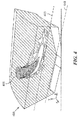
- FIG. 4 depicts a graphical representation of swirler penetration according to one or more embodiments.
- one or more swirler elements may be included around the circumference of an annular combustor.
- FIG. 4 depicts a combustor 400 and fuel-air mixture 405 controlled by a swirler relative to the inner diameter 410 of the combustor structure.
- the amount of penetration of fuel-air mixture 405 may be controlled to a depth 415 above the inner diameter panel.
- premixing of fuel-air mixture 405 may improved by the swirler configuration to reduce unwanted pollutant emissions such as NOx and smoke.
Landscapes
- Engineering & Computer Science (AREA)
- Chemical & Material Sciences (AREA)
- Combustion & Propulsion (AREA)
- Mechanical Engineering (AREA)
- General Engineering & Computer Science (AREA)
Abstract
The present disclosure relates to gas turbine engines, and in particular to combustor swirlers (120; 200; 300; 340) and swirler configurations (250; 270). In one embodiment, a swirler (120; 200; 300; 340) includes an inner passage (205; 255; 275; 330) for receiving a fuel injector and a plurality of outer passages (251, 252; 271, 272, 273; 305, 315; 350, 360, 370) concentrically arranged around the inner passage (205; 255; 275; 330). The plurality of outer passages (251, 252; 271, 272, 273; 305, 315; 350, 360, 370) include an outer vane assembly (225; 251; 271) including a plurality of vane elements (310; 355) arranged at a first angle and a first middle vane assembly (230; 252; 272) include a plurality of vane elements (320; 365) arranged at a second angle, wherein the outer vane assembly (225; 251; 271) is concentrically arranged around the first middle vane assembly (230; 252; 272), and wherein the outer vane assembly (225; 251; 271) and first middle vane assembly (230; 252; 272) are configured to produce a low net-swirl to control the penetration depth and improve premixing of a fuel air mixture for the fuel injector. According to another embodiment, the swirler (340) includes a second middle vane assembly (273) include a plurality of vane elements (375) arranged at a third angle.
Description
- This invention was made with Government support under contract number NNC13TA45T awarded by the National Aeronautics and Space Administration (NASA).
- The Government has certain rights in the invention.
- The present disclosure relates to combustion systems for gas turbine engines and, in particular, low net-swirl configurations for a combustor.
- Gas turbine engines, such as those used to power modem aircraft, to power sea vessels, to generate electrical power, and in industrial applications, include a compressor for pressurizing a supply of air, a combustor for burning a fuel in the presence of the pressurized air, and a turbine for extracting energy from the resultant combustion gases. Generally, the compressor, combustor, and turbine are disposed about a central engine axis with the compressor disposed axially upstream or forward of the combustor and the turbine disposed axially downstream of the combustor. In operation of a gas turbine engine, fuel is injected into and combusted in the combustor with compressed air from the compressor thereby generating high-temperature combustion exhaust gases, which may contain pollutant gases or smoke.
- Accordingly, there is a desire to provide configurations that improve fuel and air mixing within combustors. There is also a desire to improve the configurations of gas turbine engines and combustor assemblies to reduce unwanted pollutant emission such as NOx and smoke.
- Disclosed and claimed herein are swirlers and swirler configurations for combustors of gas turbine engines. One embodiment is directed to a swirler including an inner passage for receiving a fuel injector and a plurality of outer passages concentrically arranged around the inner passage. The plurality of outer passages include an outer vane assembly including a plurality of vane elements arranged at a first angle and a first middle vane assembly include a plurality of vane elements arranged at a second angle. The outer vane assembly is concentrically arranged around the first middle vane assembly, and the outer vane assembly and first middle vane assembly are configured to produce a low net-swirl to control the penetration depth of a fuel air mixture for the fuel injector.
- In one embodiment, the swirler is configured to generate an air and fuel mixture downstream of a combustor pilot flow and improve premixing of the fuel air mixture.
- In one embodiment, vanes of the outer vane assembly are angled within the range of +45 to +60 degrees.
- In one embodiment, vanes of the outer vane assembly are arranged and configured to handle within 50 to 70 percent of the airflow received by the swirler.
- In one embodiment, vanes of the first middle vane assembly are angled within the range of 0 to -25 degrees.
- In one embodiment, vanes of the first middle vane assembly are arranged and configured to handle within 20 to 40 percent of the airflow received by the swirler.
- In one embodiment, the penetration depth relates to the penetration depth within a combustor cavity.
- In one embodiment, the swirler generates a low net-swirl by co-swirling airflow associated with the outer vane assembly and first middle vane assembly.
- In one embodiment, the swirler includes a second middle vane assembly include a plurality of vane elements arranged at a third angle, and wherein the first middle vane assembly is arranged concentrically around the first middle vane assembly.
- In one embodiment, vanes of the outer vane assembly are angled in a direction opposite to vanes of the first middle vane assembly.
- Another embodiment is directed to a swirler including an inner passage for receiving a fuel injector and a plurality of outer passages concentrically arranged around the inner passage. The plurality of outer passages include an outer vane assembly including a plurality of vane elements arranged at a first angle, a first middle vane assembly include a plurality of vane elements arranged at a second angle, and a second middle vane assembly include a plurality of vane elements arranged at a third angle. The first middle vane assembly is concentrically arranged around the second middle vane assembly. The outer vane assembly is concentrically arranged around the first middle vane assembly and second middle assembly, and wherein the outer vane assembly, first middle vane assembly and second middle vane assembly are configured to produce a low net-swirl to control the penetration depth of a fuel air mixture for the fuel injector.
- In one embodiment, the swirler is configured to generate an air and fuel mixture downstream of a combustor pilot flow and improve premixing of the fuel air mixture.
- In one embodiment, vanes of the outer vane assembly are angled within the range of +45 to +60 degrees.
- In one embodiment, vanes of the outer vane assembly are arranged and configured to handle within 45 to 65 percent of the airflow received by the swirler.
- In one embodiment, vanes of the first middle vane assembly are angled within the range of -10 to -30 degrees and vanes of the second middle assembly are angled within the range of +10 to +30 degrees.
- In one embodiment, vanes of the first middle vane assembly are arranged and configured to handle within 15 to 25 percent of the airflow received by the swirler wherein vanes of the second middle vane assembly are arranged and configured to handle within 15 to 25 percent of the airflow received by the swirler.
- In one embodiment, the penetration depth relates to the penetration depth within a combustor cavity.
- In one embodiment, the swirler generates a low net-swirl by co-swirling airflow associated with the outer vane assembly and first middle vane assembly.
- In one embodiment, the swirler includes a second middle vane assembly include a plurality of vane elements arranged at a third angle, and wherein the first middle vane assembly is arranged concentrically around the first middle vane assembly.
- In one embodiment, vanes of the outer vane assembly and second middle vane assembly are angled in a direction opposite to vanes of the first middle vane assembly.
- In one embodiment a swirler for a combustor of a gas turbine engine is provided. The swirler having: an inner passage for receiving a fuel injector; a plurality of outer passages concentrically arranged around the inner passage, wherein the plurality of outer passages include an outer vane assembly including a plurality of vane elements arranged at a first angle; and a first middle vane assembly include a plurality of vane elements arranged at a second angle, wherein the outer vane assembly is concentrically arranged around the first middle vane assembly, and wherein the outer vane assembly and first middle vane assembly are configured to produce a low net-swirl to control the penetration depth of a fuel air mixture for the fuel injector.
- In addition to one or more of the features described above, or as an alternative to any of the foregoing embodiments, the swirler is configured to generate an air and fuel mixture downstream of a combustor pilot flow and improve premixing of the fuel air mixture.
- In addition to one or more of the features described above, or as an alternative to any of the foregoing embodiments, vanes of the outer vane assembly are angled within the range of +45 to +60 degrees.
- In addition to one or more of the features described above, or as an alternative to any of the foregoing embodiments, vanes of the outer vane assembly are arranged and configured to handle within 50 to 70 percent of the airflow received by the swirler.
- In addition to one or more of the features described above, or as an alternative to any of the foregoing embodiments, vanes of the first middle vane assembly are angled within the range of 0 to -25 degrees.
- In addition to one or more of the features described above, or as an alternative to any of the foregoing embodiments, vanes of the first middle vane assembly are arranged and configured to handle within 20 to 40 percent of the airflow received by the swirler.
- In addition to one or more of the features described above, or as an alternative to any of the foregoing embodiments, the penetration depth relates to the penetration depth within a combustor cavity.
- In addition to one or more of the features described above, or as an alternative to any of the foregoing embodiments, the swirler generates a low net-swirl by co-swirling airflow associated with the outer vane assembly and first middle vane assembly.
- In addition to one or more of the features described above, or as an alternative to any of the foregoing embodiments, the swirler further comprises a second middle vane assembly include a plurality of vane elements arranged at a third angle, and wherein the first middle vane assembly is arranged concentrically around the first middle vane assembly.
- In addition to one or more of the features described above, or as an alternative to any of the foregoing embodiments, vanes of the outer vane assembly are angled in a direction opposite to vanes of the first middle vane assembly.
- In yet another embodiment a swirler for a combustor of a gas turbine engine is provided. The swirler having: an inner passage for receiving a fuel injector; a plurality of outer passages concentrically arranged around the inner passage, wherein the plurality of outer passages include an outer vane assembly including a plurality of vane elements arranged at a first angle; a first middle vane assembly include a plurality of vane elements arranged at a second angle; and a second middle vane assembly include a plurality of vane elements arranged at a third angle, wherein the first middle vane assembly is concentrically arranged around the second middle vane assembly, wherein the outer vane assembly is concentrically arranged around the first middle vane assembly and second middle assembly, and wherein the outer vane assembly, first middle vane assembly and second middle vane assembly are configured to produce a low net-swirl to control the penetration depth of a fuel air mixture for the fuel injector.
- In addition to one or more of the features described above, or as an alternative to any of the foregoing embodiments, the swirler is configured to generate an air and fuel mixture downstream of a combustor pilot flow and improve premixing of the fuel air mixture.
- In addition to one or more of the features described above, or as an alternative to any of the foregoing embodiments, vanes of the outer vane assembly are angled within the range of +45 to +60 degrees.
- In addition to one or more of the features described above, or as an alternative to any of the foregoing embodiments, vanes of the outer vane assembly are arranged and configured to handle within 45 to 65 percent of the airflow received by the swirler.
- In addition to one or more of the features described above, or as an alternative to any of the foregoing embodiments, vanes of the first middle vane assembly are angled within the range of -10 to -30 degrees and vanes of the second middle assembly are angled within the range of +10 to +30 degrees.
- In addition to one or more of the features described above, or as an alternative to any of the foregoing embodiments, vanes of the first middle vane assembly are arranged and configured to handle within 15 to 25 percent of the airflow received by the swirler wherein vanes of the second middle vane assembly are arranged and configured to handle within 15 to 25 percent of the airflow received by the swirler.
- In addition to one or more of the features described above, or as an alternative to any of the foregoing embodiments, the penetration depth relates to the penetration depth within a combustor cavity.
- In addition to one or more of the features described above, or as an alternative to any of the foregoing embodiments, the swirler generates a low net-swirl by co-swirling airflow associated with the outer vane assembly and first middle vane assembly.
- In addition to one or more of the features described above, or as an alternative to any of the foregoing embodiments, the swirler further comprises a second middle vane assembly include a plurality of vane elements arranged at a third angle, and wherein the first middle vane assembly is arranged concentrically around the first middle vane assembly.
- In addition to one or more of the features described above, or as an alternative to any of the foregoing embodiments, vanes of the outer vane assembly and second middle vane assembly are angled in a direction opposite to vanes of the first middle vane assembly.
- Other aspects, features, and techniques will be apparent to one skilled in the relevant art in view of the following detailed description of the embodiments.
- The features, objects, and advantages of the present disclosure will become more apparent from the detailed description set forth below when taken in conjunction with the drawings in which like reference characters identify correspondingly throughout and wherein:
-
FIG. 1 depicts a cross-sectional representation of a combustor for a gas turbine engine according to one or more embodiments; -
FIGs. 2A-2B depict graphical representations of swirler configurations according to one or more embodiments; -
FIGs. 3A-3B depict graphical representations of swirler configurations according to one or more embodiments; and -
FIG. 4 depicts a graphical representation of swirler penetration according to one or more embodiments. - One aspect of this disclosure relates to configurations for a gas turbine engine and in particular a swirler for a combustor. According to one embodiment, a swirler configuration can include two or more outer passages with vane elements configured to provide a fuel-air mixture with low net-swirl. Based on the amount of swirl, the penetration depth of the fuel-air mixture may be controlled in order to increase the efficiency of fuel burn within the combustor.
- As used herein, the terms "a" or "an" shall mean one or more than one. The term "plurality" shall mean two or more than two. The term "another" is defined as a second or more. The terms "including" and/or "having" are open ended (e.g., comprising). The term "or" as used herein is to be interpreted as inclusive or meaning any one or any combination. Therefore, "A, B or C" means "any of the following: A; B; C; A and B; A and C; B and C; A, B and C". An exception to this definition will occur only when a combination of elements, functions, steps or acts are in some way inherently mutually exclusive.
- Reference throughout this document to "one embodiment," "certain embodiments," "an embodiment," or similar term means that a particular feature, structure, or characteristic described in connection with the embodiment is included in at least one embodiment. Thus, the appearances of such phrases in various places throughout this specification are not necessarily all referring to the same embodiment. Furthermore, the particular features, structures, or characteristics may be combined in any suitable manner on one or more embodiments without limitation.
- Referring now to the figures,
FIG. 1 depicts a cross-sectional representation of a combustor for a gas turbine engine according to one or more embodiments.Gas turbine engine 100 is shown includingcombustor 105 andannular structure 110.Combustor 105 extends along a portion of agas turbine engine 100 providing a gas-flow path withincombustor cavity 106. According to one embodiment,combustor 105 may be an axially controlled stoichiometry combustor.Combustor 105 includesfuel nozzle 111 which may be configured as a pilot fuel injector in the front end of the combustor and may provide a pilot fuel-air mixture 115 forcavity 106.Combustor 105 may include a second or main fuel injector downstream offuel nozzle 111. According to one embodiment,combustor 105 includesswirler 120 configured to mix air and fuel for the second or main fuel injector associated with secondary fuel-air mixture 130 forcombustor 105. - According to one embodiment,
swirler 120 may include a plurality ofpassages 125 to provide low net-swirl and as a result control the penetration depth and improve premixing of fuel-air mixture 130. By controlling the penetration depth of fuel-air mixture 130, swirler can provide a fuel-air mixture that improves the fuel burning ability of fuel-air mixture 130 by pilot fuel-air mixture 115. In that fashion, NOx (e.g., nitric oxide and nitrogen dioxide) emissions of thecombustor 105 andgas turbine engine 100 may be reduced. -
Swirler 120 may be configured for one or more fuel injectors to control the penetration of a fuel air mixture and to control premixing of the fuel air mixture. According to one embodiment,swirler 120 improves fuel and air mixing withincombustor 105 due to premixing. In addition,swirler 120 reduces unwanted pollutant emission such as NOx and smoke by controlling the penetration depth of the fuel air mixture and by combustion of substantially all fuel. -
FIGs. 2A-2B depict graphical representations of swirler configurations according to one or more embodiments. According to one embodiment,swirler 200 includes aninner passage 205 configured to receive air flow and one or more swirl passages shown as 210.Inner passage 205 is configured to receive andchannel air flow 215.Inner passage 205 may be configured to receive a fuel injector. According to one embodiment,swirler 200 includesguide structure 206 configured to channel swirler airflow with fuel output by a fuel injector withininner passage 205. - Swirl passages include outer passages concentrically arranged around the
inner passage 205, wherein the plurality of outer passages include anouter vane assembly 225 and firstmiddle vane assembly 230.Outer vane assembly 225 includes a plurality of vane elements arranged at a first angle. Firstmiddle vane assembly 230 includes a plurality of vane elements arranged at a second angle. As shown inFIG. 2A ,outer vane assembly 225 is concentrically arranged around the firstmiddle vane assembly 230.Outer vane assembly 225 and firstmiddle vane assembly 230 are configured to produce a low net-swirl to control the penetration depth of a fuel air mixture for the fuel injector, such as a main fuel injector.Outer vane assembly 225 and firstmiddle vane assembly 230 may also produce a low net-swirl to improve premixing of the fuel air mixture for the fuel injector. AlthoughFIG. 2A , is shown and described as having a two passage swirl arrangement above formed byouter vane assembly 225 and firstmiddle vane assembly 230swirler 200 may include a second middle vane assembly. - According to one embodiment, a fuel injector within
inner passage 205 may spray fuel axially as shown by 235.Axial fuel spray 235 is mixed with air output byouter vane assembly 225 and firstmiddle vane assembly 230 as fuel-air mixture 240. Fuel-air mixture may be characterized as having a low net-swirl that allows for the penetration depth of fuel-air mixture 240 to be controlled with respect to an annular structure of a combustor. -
FIG. 2B depicts a partial representation of a two pass outer passage for a swirler according to one or more embodiments.Swirler configuration 250 includes outer passage (e.g., vane assembly) 251, middle passage (e.g., vane assembly) 252, andinner passage 255.Outer passage 251 may be configured with a plurality of vanes are angled within the range of +45 to +60 degrees. Vanes of theouter passage 251 are arranged and configured to handle within 50 to 70 percent of the airflow received by the swirler. Vanes of themiddle passage 252 are angled within the range of 0 to -25 degrees and may be configured to handle within 20 to 40 percent of the airflow received by the swirler.Inner passage 255 may be configured receive 5 to 20 percent of the airflow received by the swirler. - Air flow output by
middle passage 252 andouter passage 251 co-swirls infuel spray location 260 and joins airflow ofinner passage 255 atexit 261 of the swirler. -
FIG. 2C depicts a partial representation of a three pass outer passage for a swirler according to one or more embodiments.Swirler configuration 270 includes outer passage (e.g., vane assembly) 271, middle passage (e.g., vane assembly) 272, second middle passage (e.g., vane assembly) 273, andinner passage 275.Outer passage 271 may be configured with a plurality of vanes are angled within the range of +45 to +60 degrees. Vanes of theouter passage 271 are arranged and configured to handle within 45 to 65 percent of the airflow received by the swirler. Vanes of themiddle passage 272 are angled within the range of -10 to -30 degrees and vanes of the second middle assembly are angled within the range of +10 to +30 degrees. Vanes of the firstmiddle vane assembly 272, and similarly vanes of the secondmiddle vane assembly 273 are arranged and configured to handle within 15 to 25 percent of the airflow received by the swirler.Inner passage 275 may be configured receive 5 to 20 percent of the airflow received by the swirler. - Air flow output by
outer passage 271 andmiddle passages fuel spray location 280 and joins airflow ofinner passage 275 atexit 281 of the swirler. -
FIGs. 3A-3B depict graphical representations of swirler configurations according to one or more embodiments.FIG. 3A depicts a two pass swirler including vane elements according to one or more embodiments.Swirler 300 includesouter passage 305 includingvanes 310 andmiddle passage 315 includingvanes 320. Inner passage ofswirler 300 is shown as 330.Swirler 300 is an annular structure including vanes of each passage angled in opposite directions. -
FIG. 3B depicts a three pass swirler including vane elements according to one or more embodiments.Swirler 340 includesouter passage 350 includingvanes 355,middle passage 360 includingvanes 365 andmiddle passage 370 includingvanes 375. Inner passage ofswirler 340 is shown as 330.Swirler 340 is an annular structure including vanes of each passage angled in opposite directions. -
FIG. 4 depicts a graphical representation of swirler penetration according to one or more embodiments. According to one embodiment, one or more swirler elements may be included around the circumference of an annular combustor.FIG. 4 depicts acombustor 400 and fuel-air mixture 405 controlled by a swirler relative to theinner diameter 410 of the combustor structure. According to one embodiment, the amount of penetration of fuel-air mixture 405 may be controlled to adepth 415 above the inner diameter panel. - According to another embodiment, premixing of fuel-
air mixture 405 may improved by the swirler configuration to reduce unwanted pollutant emissions such as NOx and smoke. - While this disclosure has been particularly shown and described with references to exemplary embodiments thereof, it will be understood by those skilled in the art that various changes in form and details may be made therein without departing from the scope of the claimed embodiments.
- The following clauses set out features of the invention which may or may not presently be claimed in this application, but which may form the basis for future amendment or a divisional application.
- 1. A swirler for a combustor of a gas turbine engine, the swirler comprising:
- an inner passage for receiving a fuel injector;
- a plurality of outer passages concentrically arranged around the inner passage, wherein the plurality of outer passages include
- an outer vane assembly including a plurality of vane elements arranged at a first angle; and
- a first middle vane assembly include a plurality of vane elements arranged at a second angle,
- wherein the outer vane assembly is concentrically arranged around the first middle vane assembly, and wherein the outer vane assembly and first middle vane assembly are configured to produce a low net-swirl to control the penetration depth of a fuel air mixture for the fuel injector.
- 2. The swirler of clause 1, wherein the swirler is configured to generate an air and fuel mixture downstream of a combustor pilot flow and improve premixing of the fuel air mixture.
- 3. The swirler of clause 1, wherein vanes of the outer vane assembly are angled within the range of +45 to +60 degrees.
- 4. The swirler of clause 1, wherein vanes of the outer vane assembly are arranged and configured to handle within 50 to 70 percent of the airflow received by the swirler.
- 5. The swirler of clause 1, wherein vanes of the first middle vane assembly are angled within the range of 0 to -25 degrees.
- 6. The swirler of clause 1, wherein vanes of the first middle vane assembly are arranged and configured to handle within 20 to 40 percent of the airflow received by the swirler.
- 7. The swirler of clause 1, wherein the penetration depth relates to the penetration depth within a combustor cavity.
- 8. The swirler of clause 1, wherein the swirler generates a low net-swirl by co-swirling airflow associated with the outer vane assembly and first middle vane assembly.
- 9. The swirler of clause 1, further comprising a second middle vane assembly include a plurality of vane elements arranged at a third angle, and wherein the first middle vane assembly is arranged concentrically around the first middle vane assembly.
- 10. The swirler of clause 1, wherein vanes of the outer vane assembly are angled in a direction opposite to vanes of the first middle vane assembly.
- 11. A swirler for a combustor of a gas turbine engine, the swirler comprising:
- an inner passage for receiving a fuel injector;
a plurality of outer passages concentrically arranged around the inner passage, - wherein the plurality of outer passages include
an outer vane assembly including a plurality of vane elements arranged at a first angle;
a first middle vane assembly include a plurality of vane elements arranged at a second angle; and
a second middle vane assembly include a plurality of vane elements arranged at a third angle, wherein the first middle vane assembly is concentrically arranged around the second middle vane assembly,
wherein the outer vane assembly is concentrically arranged around the first middle vane assembly and second middle assembly, and wherein the outer vane assembly, first middle vane assembly and second middle vane assembly are configured to produce a low net-swirl to control the penetration depth of a fuel air mixture for the fuel injector.
- an inner passage for receiving a fuel injector;
- 12. The swirler of clause 11, wherein the swirler is configured to generate an air and fuel mixture downstream of a combustor pilot flow and improve premixing of the fuel air mixture.
- 13. The swirler of clause 11, wherein vanes of the outer vane assembly are angled within the range of +45 to +60 degrees.
- 14. The swirler of clause 11, wherein vanes of the outer vane assembly are arranged and configured to handle within 45 to 65 percent of the airflow received by the swirler.
- 15. The swirler of clause 11, wherein vanes of the first middle vane assembly are angled within the range of -10 to -30 degrees and vanes of the second middle assembly are angled within the range of +10 to +30 degrees.
- 16. The swirler of clause 11, wherein vanes of the first middle vane assembly are arranged and configured to handle within 15 to 25 percent of the airflow received by the swirler wherein vanes of the second middle vane assembly are arranged and configured to handle within 15 to 25 percent of the airflow received by the swirler.
- 17. The swirler of clause 11, wherein the penetration depth relates to the penetration depth within a combustor cavity.
- 18. The swirler of clause 11, wherein the swirler generates a low net-swirl by co-swirling airflow associated with the outer vane assembly and first middle vane assembly.
- 19. The swirler of clause 11, further comprising a second middle vane assembly include a plurality of vane elements arranged at a third angle, and wherein the first middle vane assembly is arranged concentrically around the first middle vane assembly.
- 20. The swirler of clause 11, wherein vanes of the outer vane assembly and second middle vane assembly are angled in a direction opposite to vanes of the first middle vane assembly.
Claims (15)
- A swirler (120; 200; 300; 340) for a combustor (105; 400) of a gas turbine engine (100), the swirler (120; 200; 300; 340) comprising:an inner passage (205; 255; 275; 330) for receiving a fuel injector;a plurality of outer passages (251, 252; 271, 272, 273; 305, 315; 350, 360, 370) concentrically arranged around the inner passage (205; 255; 275; 330), wherein the plurality of outer passages (251, 252; 271, 272, 273; 305, 315; 350, 360, 370) includean outer vane assembly (225; 251; 271) including a plurality of vane elements (310; 355) arranged at a first angle; anda first middle vane assembly (230; 252; 272) including a plurality of vane elements (320; 365) arranged at a second angle,wherein the outer vane assembly (225; 251; 271) is concentrically arranged around the first middle vane assembly (230; 252; 272), and wherein the outer vane assembly (225; 251; 271) and first middle vane assembly (230; 252; 272) are configured to produce a low net-swirl to control the penetration depth of a fuel air mixture for the fuel injector.
- The swirler (120; 200; 300; 340) of claim 1, wherein the swirler is configured to generate an air and fuel mixture (130; 240; 405) downstream of a combustor pilot flow (115) and improve premixing of the fuel air mixture.
- The swirler (120; 200; 300; 340) of claim 1 or 2, wherein vanes (310; 355) of the outer vane assembly (225; 251; 271) are angled within the range of +45 to +60 degrees, and/or wherein vanes (320; 365) of the first middle vane assembly (230; 252) are angled within the range of 0 to -25 degrees.
- The swirler (120; 200; 300; 340) of any preceding claim, wherein vanes (310; 355) of the outer vane assembly (251) are arranged and configured to handle within 50 to 70 percent of the airflow received by the swirler, and/or wherein vanes (320; 365) of the first middle vane assembly (252) are arranged and configured to handle within 20 to 40 percent of the airflow received by the swirler.
- The swirler (120; 200; 300; 340) of any preceding claim, wherein the penetration depth relates to the penetration depth (415) within a combustor cavity (400).
- The swirler (120; 200; 300; 340) of any preceding claim, wherein the swirler generates a low net-swirl by co-swirling airflow associated with the outer vane assembly (225; 251; 271) and first middle vane assembly (230; 252; 272).
- The swirler (120; 340) of any preceding claim, further comprising a second middle vane assembly (273) including a plurality of vane elements (375) arranged at a third angle, and wherein the first middle vane assembly (272) is arranged concentrically around the second middle vane assembly (273).
- The swirler (120; 200; 300; 340) of any preceding claim, wherein vanes (310; 355) of the outer vane assembly (251; 271) are angled in a direction opposite to vanes (320; 365) of the first middle vane assembly (252; 272).
- A swirler (120; 340) for a combustor (105; 400) of a gas turbine engine (100), the swirler (120; 340) comprising:an inner passage (275; 330) for receiving a fuel injector;a plurality of outer passages (271, 272, 273; 350, 360, 370) concentrically arranged around the inner passage (275; 330), wherein the plurality of outer passages includean outer vane assembly (271) including a plurality of vane elements (355) arranged at a first angle;a first middle vane assembly (272) including a plurality of vane elements (365) arranged at a second angle; anda second middle vane assembly (273) including a plurality of vane elements (375) arranged at a third angle, wherein the first middle vane assembly (272) is concentrically arranged around the second middle vane assembly (273),wherein the outer vane assembly (271) is concentrically arranged around the first middle vane assembly (272) and second middle assembly (273), and wherein the outer vane assembly (271), first middle vane assembly (272) and second middle vane assembly (273) are configured to produce a low net-swirl to control the penetration depth of a fuel air mixture for the fuel injector.
- The swirler (120; 340) of claim 9, wherein the swirler is configured to generate an air and fuel mixture (130; 240; 405) downstream of a combustor pilot flow (115) and improve premixing of the fuel air mixture.
- The swirler (120; 340) of claim 9 or 10, wherein vanes (355) of the outer vane assembly (271) are angled within the range of +45 to +60 degrees, and/or wherein vanes (365) of the first middle vane assembly (272) are angled within the range of -10 to -30 degrees and vanes (375) of the second middle assembly (273) are angled within the range of +10 to +30 degrees.
- The swirler (120; 340) of claim 9, 10 or 11, wherein vanes (355) of the outer vane assembly (271) are arranged and configured to handle within 45 to 65 percent of the airflow received by the swirler, and/or wherein vanes (365) of the first middle vane assembly (272) are arranged and configured to handle within 15 to 25 percent of the airflow received by the swirler and/or vanes (375) of the second middle vane assembly (273) are arranged and configured to handle within 15 to 25 percent of the airflow received by the swirler.
- The swirler (120; 340) of any of claims 9 to 12, wherein the penetration depth relates to the penetration depth (415) within a combustor cavity (400).
- The swirler (120; 340) of any of claims 9 to 13, wherein the swirler generates a low net-swirl by co-swirling airflow associated with the outer vane assembly (271) and first middle vane assembly (272).
- The swirler (120; 340) of any of claims 9 to 14, wherein vanes (355, 375) of the outer vane assembly (271) and second middle vane assembly (273) are angled in a direction opposite to vanes (365) of the first middle vane assembly (272).
Applications Claiming Priority (1)
| Application Number | Priority Date | Filing Date | Title |
|---|---|---|---|
| US14/636,689 US20160258627A1 (en) | 2015-03-03 | 2015-03-03 | Low net-swirl configurations for gas turbine engine combustors |
Publications (1)
| Publication Number | Publication Date |
|---|---|
| EP3096083A1 true EP3096083A1 (en) | 2016-11-23 |
Family
ID=55027620
Family Applications (1)
| Application Number | Title | Priority Date | Filing Date |
|---|---|---|---|
| EP15203242.1A Withdrawn EP3096083A1 (en) | 2015-03-03 | 2015-12-31 | Low net-swirl configurations for gas turbine engine combustors |
Country Status (2)
| Country | Link |
|---|---|
| US (1) | US20160258627A1 (en) |
| EP (1) | EP3096083A1 (en) |
Families Citing this family (5)
| Publication number | Priority date | Publication date | Assignee | Title |
|---|---|---|---|---|
| US10508811B2 (en) * | 2016-10-03 | 2019-12-17 | United Technologies Corporation | Circumferential fuel shifting and biasing in an axial staged combustor for a gas turbine engine |
| US11175045B2 (en) | 2018-01-04 | 2021-11-16 | General Electric Company | Fuel nozzle for gas turbine engine combustor |
| US11619172B1 (en) | 2022-03-01 | 2023-04-04 | General Electric Company | Detonation combustion systems |
| EP4511597A1 (en) * | 2022-06-01 | 2025-02-26 | Siemens Energy Global GmbH & Co. KG | Combustor having secondary fuel injector |
| US12130016B1 (en) | 2023-05-31 | 2024-10-29 | General Electric Company | Turbine engine including a combustor |
Citations (2)
| Publication number | Priority date | Publication date | Assignee | Title |
|---|---|---|---|---|
| EP1909032A2 (en) * | 2006-10-05 | 2008-04-09 | General Electric Company | Method and apparatus for reducing gas turbine engine emissions |
| EP3054220A2 (en) * | 2015-01-21 | 2016-08-10 | United Technologies Corporation | Bluff body fuel mixer |
Family Cites Families (1)
| Publication number | Priority date | Publication date | Assignee | Title |
|---|---|---|---|---|
| US2958195A (en) * | 1959-02-25 | 1960-11-01 | Philip G Dooley | Air inlet construction |
-
2015
- 2015-03-03 US US14/636,689 patent/US20160258627A1/en not_active Abandoned
- 2015-12-31 EP EP15203242.1A patent/EP3096083A1/en not_active Withdrawn
Patent Citations (2)
| Publication number | Priority date | Publication date | Assignee | Title |
|---|---|---|---|---|
| EP1909032A2 (en) * | 2006-10-05 | 2008-04-09 | General Electric Company | Method and apparatus for reducing gas turbine engine emissions |
| EP3054220A2 (en) * | 2015-01-21 | 2016-08-10 | United Technologies Corporation | Bluff body fuel mixer |
Also Published As
| Publication number | Publication date |
|---|---|
| US20160258627A1 (en) | 2016-09-08 |
Similar Documents
| Publication | Publication Date | Title |
|---|---|---|
| EP2626635B1 (en) | Combustor assembly with trapped vortex cavity | |
| US8973368B2 (en) | Mixer assembly for a gas turbine engine | |
| US10480791B2 (en) | Fuel injector to facilitate reduced NOx emissions in a combustor system | |
| US10718524B2 (en) | Mixer assembly for a gas turbine engine | |
| US9435537B2 (en) | System and method for premixer wake and vortex filling for enhanced flame-holding resistance | |
| US8117845B2 (en) | Systems to facilitate reducing flashback/flame holding in combustion systems | |
| US8312724B2 (en) | Mixer assembly for a gas turbine engine having a pilot mixer with a corner flame stabilizing recirculation zone | |
| JP5364275B2 (en) | Method and system for enabling NOx emissions to be reduced in a combustion system | |
| EP2163819B1 (en) | Gas turbine combustor | |
| EP3341656B1 (en) | Fuel nozzle assembly for a gas turbine | |
| US9297534B2 (en) | Combustor portion for a turbomachine and method of operating a turbomachine | |
| EP2584261A1 (en) | Diffusion nozzles for low-oxygen fuel nozzle assembly and method | |
| EP3096083A1 (en) | Low net-swirl configurations for gas turbine engine combustors | |
| CN102809176A (en) | Aerodynamic fuel nozzle | |
| US10823420B2 (en) | Pilot nozzle with inline premixing | |
| CN119137414A (en) | Method for injecting a hydrogen-air mixture into a turbine engine combustor | |
| EP2503243A1 (en) | Combustor with fuel nozzle liner having chevron ribs | |
| US6775983B2 (en) | Flow control device for a combustor | |
| EP3043116A1 (en) | Mixer assembly for a gas turbine engine | |
| EP3702669B1 (en) | Method for operating a sequential combustor of a gas turbine and a gas turbine comprising this sequential combustor | |
| WO2024116966A1 (en) | Method for operating gas turbine | |
| CN119816689A (en) | Device and method for injecting a hydrogen-air mixture into a turbine engine combustor |
Legal Events
| Date | Code | Title | Description |
|---|---|---|---|
| PUAI | Public reference made under article 153(3) epc to a published international application that has entered the european phase |
Free format text: ORIGINAL CODE: 0009012 |
|
| AK | Designated contracting states |
Kind code of ref document: A1 Designated state(s): AL AT BE BG CH CY CZ DE DK EE ES FI FR GB GR HR HU IE IS IT LI LT LU LV MC MK MT NL NO PL PT RO RS SE SI SK SM TR |
|
| AX | Request for extension of the european patent |
Extension state: BA ME |
|
| STAA | Information on the status of an ep patent application or granted ep patent |
Free format text: STATUS: THE APPLICATION IS DEEMED TO BE WITHDRAWN |
|
| 18D | Application deemed to be withdrawn |
Effective date: 20170524 |