EP3096040A1 - Active system for bearing oil damper supply and vibration control - Google Patents
Active system for bearing oil damper supply and vibration control Download PDFInfo
- Publication number
- EP3096040A1 EP3096040A1 EP16169379.1A EP16169379A EP3096040A1 EP 3096040 A1 EP3096040 A1 EP 3096040A1 EP 16169379 A EP16169379 A EP 16169379A EP 3096040 A1 EP3096040 A1 EP 3096040A1
- Authority
- EP
- European Patent Office
- Prior art keywords
- fluid
- bearing
- variable position
- position valve
- compartment
- Prior art date
- Legal status (The legal status is an assumption and is not a legal conclusion. Google has not performed a legal analysis and makes no representation as to the accuracy of the status listed.)
- Granted
Links
Images




Classifications
-
- F—MECHANICAL ENGINEERING; LIGHTING; HEATING; WEAPONS; BLASTING
- F01—MACHINES OR ENGINES IN GENERAL; ENGINE PLANTS IN GENERAL; STEAM ENGINES
- F01D—NON-POSITIVE DISPLACEMENT MACHINES OR ENGINES, e.g. STEAM TURBINES
- F01D25/00—Component parts, details, or accessories, not provided for in, or of interest apart from, other groups
- F01D25/16—Arrangement of bearings; Supporting or mounting bearings in casings
- F01D25/162—Bearing supports
- F01D25/164—Flexible supports; Vibration damping means associated with the bearing
-
- F—MECHANICAL ENGINEERING; LIGHTING; HEATING; WEAPONS; BLASTING
- F01—MACHINES OR ENGINES IN GENERAL; ENGINE PLANTS IN GENERAL; STEAM ENGINES
- F01D—NON-POSITIVE DISPLACEMENT MACHINES OR ENGINES, e.g. STEAM TURBINES
- F01D25/00—Component parts, details, or accessories, not provided for in, or of interest apart from, other groups
- F01D25/18—Lubricating arrangements
- F01D25/20—Lubricating arrangements using lubrication pumps
-
- F—MECHANICAL ENGINEERING; LIGHTING; HEATING; WEAPONS; BLASTING
- F16—ENGINEERING ELEMENTS AND UNITS; GENERAL MEASURES FOR PRODUCING AND MAINTAINING EFFECTIVE FUNCTIONING OF MACHINES OR INSTALLATIONS; THERMAL INSULATION IN GENERAL
- F16C—SHAFTS; FLEXIBLE SHAFTS; ELEMENTS OR CRANKSHAFT MECHANISMS; ROTARY BODIES OTHER THAN GEARING ELEMENTS; BEARINGS
- F16C27/00—Elastic or yielding bearings or bearing supports, for exclusively rotary movement
- F16C27/04—Ball or roller bearings, e.g. with resilient rolling bodies
- F16C27/045—Ball or roller bearings, e.g. with resilient rolling bodies with a fluid film, e.g. squeeze film damping
-
- F—MECHANICAL ENGINEERING; LIGHTING; HEATING; WEAPONS; BLASTING
- F16—ENGINEERING ELEMENTS AND UNITS; GENERAL MEASURES FOR PRODUCING AND MAINTAINING EFFECTIVE FUNCTIONING OF MACHINES OR INSTALLATIONS; THERMAL INSULATION IN GENERAL
- F16C—SHAFTS; FLEXIBLE SHAFTS; ELEMENTS OR CRANKSHAFT MECHANISMS; ROTARY BODIES OTHER THAN GEARING ELEMENTS; BEARINGS
- F16C35/00—Rigid support of bearing units; Housings, e.g. caps, covers
- F16C35/04—Rigid support of bearing units; Housings, e.g. caps, covers in the case of ball or roller bearings
- F16C35/06—Mounting or dismounting of ball or roller bearings; Fixing them onto shaft or in housing
- F16C35/067—Fixing them in a housing
-
- F—MECHANICAL ENGINEERING; LIGHTING; HEATING; WEAPONS; BLASTING
- F16—ENGINEERING ELEMENTS AND UNITS; GENERAL MEASURES FOR PRODUCING AND MAINTAINING EFFECTIVE FUNCTIONING OF MACHINES OR INSTALLATIONS; THERMAL INSULATION IN GENERAL
- F16F—SPRINGS; SHOCK-ABSORBERS; MEANS FOR DAMPING VIBRATION
- F16F15/00—Suppression of vibrations in systems; Means or arrangements for avoiding or reducing out-of-balance forces, e.g. due to motion
- F16F15/02—Suppression of vibrations of non-rotating, e.g. reciprocating systems; Suppression of vibrations of rotating systems by use of members not moving with the rotating systems
- F16F15/023—Suppression of vibrations of non-rotating, e.g. reciprocating systems; Suppression of vibrations of rotating systems by use of members not moving with the rotating systems using fluid means
- F16F15/0237—Suppression of vibrations of non-rotating, e.g. reciprocating systems; Suppression of vibrations of rotating systems by use of members not moving with the rotating systems using fluid means involving squeeze-film damping
-
- F—MECHANICAL ENGINEERING; LIGHTING; HEATING; WEAPONS; BLASTING
- F05—INDEXING SCHEMES RELATING TO ENGINES OR PUMPS IN VARIOUS SUBCLASSES OF CLASSES F01-F04
- F05D—INDEXING SCHEME FOR ASPECTS RELATING TO NON-POSITIVE-DISPLACEMENT MACHINES OR ENGINES, GAS-TURBINES OR JET-PROPULSION PLANTS
- F05D2220/00—Application
- F05D2220/30—Application in turbines
- F05D2220/32—Application in turbines in gas turbines
-
- F—MECHANICAL ENGINEERING; LIGHTING; HEATING; WEAPONS; BLASTING
- F05—INDEXING SCHEMES RELATING TO ENGINES OR PUMPS IN VARIOUS SUBCLASSES OF CLASSES F01-F04
- F05D—INDEXING SCHEME FOR ASPECTS RELATING TO NON-POSITIVE-DISPLACEMENT MACHINES OR ENGINES, GAS-TURBINES OR JET-PROPULSION PLANTS
- F05D2240/00—Components
- F05D2240/50—Bearings
-
- F—MECHANICAL ENGINEERING; LIGHTING; HEATING; WEAPONS; BLASTING
- F05—INDEXING SCHEMES RELATING TO ENGINES OR PUMPS IN VARIOUS SUBCLASSES OF CLASSES F01-F04
- F05D—INDEXING SCHEME FOR ASPECTS RELATING TO NON-POSITIVE-DISPLACEMENT MACHINES OR ENGINES, GAS-TURBINES OR JET-PROPULSION PLANTS
- F05D2240/00—Components
- F05D2240/50—Bearings
- F05D2240/54—Radial bearings
-
- F—MECHANICAL ENGINEERING; LIGHTING; HEATING; WEAPONS; BLASTING
- F05—INDEXING SCHEMES RELATING TO ENGINES OR PUMPS IN VARIOUS SUBCLASSES OF CLASSES F01-F04
- F05D—INDEXING SCHEME FOR ASPECTS RELATING TO NON-POSITIVE-DISPLACEMENT MACHINES OR ENGINES, GAS-TURBINES OR JET-PROPULSION PLANTS
- F05D2240/00—Components
- F05D2240/90—Mounting on supporting structures or systems
-
- F—MECHANICAL ENGINEERING; LIGHTING; HEATING; WEAPONS; BLASTING
- F05—INDEXING SCHEMES RELATING TO ENGINES OR PUMPS IN VARIOUS SUBCLASSES OF CLASSES F01-F04
- F05D—INDEXING SCHEME FOR ASPECTS RELATING TO NON-POSITIVE-DISPLACEMENT MACHINES OR ENGINES, GAS-TURBINES OR JET-PROPULSION PLANTS
- F05D2260/00—Function
- F05D2260/96—Preventing, counteracting or reducing vibration or noise
-
- F—MECHANICAL ENGINEERING; LIGHTING; HEATING; WEAPONS; BLASTING
- F05—INDEXING SCHEMES RELATING TO ENGINES OR PUMPS IN VARIOUS SUBCLASSES OF CLASSES F01-F04
- F05D—INDEXING SCHEME FOR ASPECTS RELATING TO NON-POSITIVE-DISPLACEMENT MACHINES OR ENGINES, GAS-TURBINES OR JET-PROPULSION PLANTS
- F05D2270/00—Control
- F05D2270/30—Control parameters, e.g. input parameters
- F05D2270/301—Pressure
-
- F—MECHANICAL ENGINEERING; LIGHTING; HEATING; WEAPONS; BLASTING
- F05—INDEXING SCHEMES RELATING TO ENGINES OR PUMPS IN VARIOUS SUBCLASSES OF CLASSES F01-F04
- F05D—INDEXING SCHEME FOR ASPECTS RELATING TO NON-POSITIVE-DISPLACEMENT MACHINES OR ENGINES, GAS-TURBINES OR JET-PROPULSION PLANTS
- F05D2270/00—Control
- F05D2270/30—Control parameters, e.g. input parameters
- F05D2270/303—Temperature
-
- F—MECHANICAL ENGINEERING; LIGHTING; HEATING; WEAPONS; BLASTING
- F05—INDEXING SCHEMES RELATING TO ENGINES OR PUMPS IN VARIOUS SUBCLASSES OF CLASSES F01-F04
- F05D—INDEXING SCHEME FOR ASPECTS RELATING TO NON-POSITIVE-DISPLACEMENT MACHINES OR ENGINES, GAS-TURBINES OR JET-PROPULSION PLANTS
- F05D2270/00—Control
- F05D2270/30—Control parameters, e.g. input parameters
- F05D2270/309—Rate of change of parameters
-
- F—MECHANICAL ENGINEERING; LIGHTING; HEATING; WEAPONS; BLASTING
- F05—INDEXING SCHEMES RELATING TO ENGINES OR PUMPS IN VARIOUS SUBCLASSES OF CLASSES F01-F04
- F05D—INDEXING SCHEME FOR ASPECTS RELATING TO NON-POSITIVE-DISPLACEMENT MACHINES OR ENGINES, GAS-TURBINES OR JET-PROPULSION PLANTS
- F05D2270/00—Control
- F05D2270/30—Control parameters, e.g. input parameters
- F05D2270/334—Vibration measurements
-
- F—MECHANICAL ENGINEERING; LIGHTING; HEATING; WEAPONS; BLASTING
- F16—ENGINEERING ELEMENTS AND UNITS; GENERAL MEASURES FOR PRODUCING AND MAINTAINING EFFECTIVE FUNCTIONING OF MACHINES OR INSTALLATIONS; THERMAL INSULATION IN GENERAL
- F16C—SHAFTS; FLEXIBLE SHAFTS; ELEMENTS OR CRANKSHAFT MECHANISMS; ROTARY BODIES OTHER THAN GEARING ELEMENTS; BEARINGS
- F16C19/00—Bearings with rolling contact, for exclusively rotary movement
- F16C19/02—Bearings with rolling contact, for exclusively rotary movement with bearing balls essentially of the same size in one or more circular rows
- F16C19/04—Bearings with rolling contact, for exclusively rotary movement with bearing balls essentially of the same size in one or more circular rows for radial load mainly
- F16C19/06—Bearings with rolling contact, for exclusively rotary movement with bearing balls essentially of the same size in one or more circular rows for radial load mainly with a single row or balls
-
- F—MECHANICAL ENGINEERING; LIGHTING; HEATING; WEAPONS; BLASTING
- F16—ENGINEERING ELEMENTS AND UNITS; GENERAL MEASURES FOR PRODUCING AND MAINTAINING EFFECTIVE FUNCTIONING OF MACHINES OR INSTALLATIONS; THERMAL INSULATION IN GENERAL
- F16C—SHAFTS; FLEXIBLE SHAFTS; ELEMENTS OR CRANKSHAFT MECHANISMS; ROTARY BODIES OTHER THAN GEARING ELEMENTS; BEARINGS
- F16C19/00—Bearings with rolling contact, for exclusively rotary movement
- F16C19/52—Bearings with rolling contact, for exclusively rotary movement with devices affected by abnormal or undesired conditions
- F16C19/527—Bearings with rolling contact, for exclusively rotary movement with devices affected by abnormal or undesired conditions related to vibration and noise
-
- F—MECHANICAL ENGINEERING; LIGHTING; HEATING; WEAPONS; BLASTING
- F16—ENGINEERING ELEMENTS AND UNITS; GENERAL MEASURES FOR PRODUCING AND MAINTAINING EFFECTIVE FUNCTIONING OF MACHINES OR INSTALLATIONS; THERMAL INSULATION IN GENERAL
- F16C—SHAFTS; FLEXIBLE SHAFTS; ELEMENTS OR CRANKSHAFT MECHANISMS; ROTARY BODIES OTHER THAN GEARING ELEMENTS; BEARINGS
- F16C2360/00—Engines or pumps
- F16C2360/23—Gas turbine engines
Definitions
- Gas turbine engines can include fluid damped bearings to help maintain vibration and displacement of rotating components within acceptable limits.
- these fluid damped bearings are fed oil from the engine oil system and accept the oil at a pressure generated by the system.
- Typical systems regulate fluid flow to the fluid damped bearing with a valve that switches between on and off positions. In some cases, however, alternating between on and off positions exclusively can cause the oil flow rate to stray from an optimal flow rate to a rate that is either too high or too low. Either condition can lead to undesired vibration and displacement of rotating components during operation of the gas turbine engine.
- a fluid damped bearing system that can help maintain an optimum flow of fluid to the fluid damped bearing during operation of the gas turbine engine.
- a bearing damping system includes a pump configured to pump a fluid through the system.
- the system further includes a variable position valve connected to the pump by a first conduit and having a plurality of open positions each configured to generate a different flow in the fluid downstream from the variable position valve.
- the system also includes a bearing assembly connected to the variable position valve by a second conduit.
- the bearing assembly includes a bearing housing having an outer surface and an inner surface.
- the bearing housing is configured to be attached to a stationary structure.
- the bearing assembly also includes a stationary bearing race having an outer surface and an inner surface and is positioned within the bearing housing.
- the bearing assembly also includes a rotating bearing race having an outer surface and an inner surface spaced apart from the stationary bearing race and configured to be attached to a rotating component.
- a bearing element is disposed between the inner surface of the stationary bearing race and the outer surface of the rotating race.
- a fluid compartment is defined by the space between the inner surface of the bearing housing and the outer surface of the stationary race and is configured to receive the fluid from the second
- a gas turbine engine includes a stationary section and a rotating section joined to a shaft.
- the gas turbine engine also includes a bearing housing having a radially outer surface and a radially inner surface.
- the bearing housing is attached to the stationary section of the gas turbine engine.
- a stationary bearing race having a radially outer surface and a radially inner surface is spaced radially inward from the bearing housing.
- a rotating bearing race having a radially outer surface and a radially inner surface is spaced radially inward from the stationary bearing race and attached to the shaft.
- a bearing element is disposed between the radially inner surface of the stationary bearing race and the radially outer surface of the rotating bearing race.
- a fluid compartment is defined by the space between the radially inner surface of the bearing housing and the radially outer surface of the stationary race.
- the gas turbine engine also includes a pump configured to pump a fluid into the fluid compartment.
- the gas turbine engine further includes a variable position valve disposed between the fluid compartment and the pump. The variable position valve has a plurality of open positions configured to generate a plurality of fluid flows within the fluid compartment.
- a method of adjusting a stiffness of a fluid damped bearing includes the step of pumping a fluid through a variable position valve having a plurality of open positions. The method further includes the step of sensing a parameter relating to a vibration rate of a rotating component. The method also includes the step of actuating a variable position valve in response to the sensed parameter to control a flow of a fluid. The method additionally includes the step of routing the fluid from the variable position valve to a fluid compartment formed between a bearing housing and a stationary race of the fluid damped bearing.
- This disclosure is directed towards fluid damped bearings. More particularly, this disclosure is directed towards regulating the fluid pressure in fluid damped bearings.
- FIG. 1 is a sectional view of gas turbine engine 10.
- Gas turbine engine (or turbine engine) 10 includes a power core with compressor section 12, combustor 14 and turbine section 16 arranged in flow series between upstream inlet 18 and downstream exhaust 20.
- Compressor section 12 and turbine section 16 are arranged into a number of alternating stages of rotor airfoils (or blades) 22 and stator airfoils (or vanes) 24.
- propulsion fan 26 is positioned in bypass duct 28, which is coaxially oriented about the engine core along centerline (or turbine axis) C L .
- An open-rotor propulsion stage 26 may also be provided, with turbine engine 10 operating as a turboprop or unducted turbofan engine.
- fan rotor 26 and bypass duct 28 may be absent, with turbine engine 10 configured as a turbojet or turboshaft engine, or an industrial gas turbine.
- Gas turbine engine 10 can also include geared architecture such as a fan drive gear system.
- compressor section 12 includes low pressure compressor (LPC) 30 and high pressure compressor (HPC) 32, and turbine section 16 includes high pressure turbine (HPT) 34 and low pressure turbine (LPT) 36.
- Low pressure compressor 30 is rotationally coupled to low pressure turbine 36 via low pressure (LP) shaft 38, forming the LP spool or low spool.
- High pressure compressor 32 is rotationally coupled to high pressure turbine 34 via high pressure (HP) shaft 40, forming the HP spool or high spool.
- Flow F at inlet 18 divides into primary (core) flow F P and secondary (bypass) flow F S downstream of fan rotor 26.
- Primary flow F P is compressed in low pressure compressor 30 and high pressure compressor 32, and then mixed with fuel in combustor 14 and ignited to generate hot combustion gas.
- the combustion gas expands to provide rotational energy in high pressure turbine 34 and low pressure turbine 36, driving high pressure compressor 32 and low pressure compressor 30, respectively.
- Expanded combustion gases exit through exhaust section (or exhaust nozzle) 20, which can be shaped or actuated to regulate the exhaust flow and improve thrust performance.
- Low pressure shaft 38 and high pressure shaft 40 are mounted coaxially about centerline C L , and rotate at different speeds.
- Fan rotor (or other propulsion stage) 26 is rotationally coupled to low pressure shaft 38.
- Each shaft is associated with at least one bearing such as damped ball bearing 42 or damped roller bearing 44.
- Turbine efficiency and performance depends on the overall pressure ratio, defined by the total pressure at inlet 18 as compared to the exit pressure of compressor section 12, for example at the outlet of high pressure compressor 32, entering combustor 14.
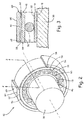
- FIG. 2 is a perspective sectional view of damped ball bearing 42. Although FIG. 2 shows damped ball bearing 42, the concepts described below are equally applicable to damped roller bearing 44.
- FIG. 2 includes rotating race 46, which includes rotating race radially inner surface 48 and rotating race radially outer surface 50; bearing element 52, stationary race 54, which includes stationary race radially inner surface 56 and stationary race radially outer surface 58; bearing housing 60, which includes bearing housing radially inner surface 62 and bearing housing radially outer surface 64; and fluid compartment 66.
- Low pressure shaft 38 defines a central rotational axis of gas turbine engine 10. As stated above, low pressure shaft 38 drives rotation of propulsion fan 26, low pressure compressor 30, and low pressure turbine 36 which define the LP spool. Although low pressure shaft 38 is depicted in FIG. 2 , this description can also apply to high pressure shaft 40 which drives rotation of high pressure compressor 32 and high pressure turbine 34 which define the HP spool. Damped ball bearing 42 surrounds low pressure shaft 38. Damped ball bearing 42 helps to facilitate rotation of low pressure shaft 38.
- Rotating race 46 of damped ball bearing 42 is annularly shaped and circumscribes low pressure shaft 38.
- Rotating race 46 includes rotating race radially inner surface 48 and rotating race radially outer surface 50.
- Low pressure shaft 38 is joined to rotating race inner surface 48.
- Rotating race radially outer surface 50 interfaces with bearing element 52.
- bearing element 52 is a ball but in other embodiments bearing element 52 can be a cylindrical roller or a tapered roller bearing.
- Stationary race 54 of damped ball bearing 42 circumscribes and is spaced apart from rotating race 46.
- Stationary race 54 includes radially inner surface 56 and radially outer surface 58.
- Stationary race radially inner surface 56 is spaced apart from rotating race radially outer surface 50 and bearing element 52 is disposed therebetween.
- Bearing housing 60 of damped ball bearing 42, circumscribes stationary race 54 and includes bearing housing radially inner surface 62 and bearing housing radially outer surface 64.
- Bearing housing radially inner surface 62 is joined to stationary race radially outer surface 58.
- a space is formed between bearing housing radially inner surface 62 and stationary race radially outer surface 58 which defines fluid compartment 66.
- Bearing housing radially outer surface 64 is joined to a non-rotating stationary structure of gas turbine engine 10.
- FIG. 3 is a sectional view of damped ball bearing 42 taken along line 2-2 from FIG. 2.
- FIG. 3 additionally illustrates radial extensions 68.
- Radial extensions 68 extend from the axial ends of stationary race radially outer surface 58.
- Radial extensions 68 are joined to bearing housing radially inner surface 62 and seal fluid compartment 66.
- radial extensions 68 can be replaced with piston rings or O-rings.
- low pressure shaft 38 rotates as core air flow flows through gas turbine engine 10.
- Rotating race 46 rotates along with low pressure shaft 38.
- the rotation is facilitated by bearing elements 52.
- Bearing elements 52 also help to keep low pressure shaft 38 in a proper position because they are sized to fit between rotating race 46 and stationary race 54 so as to maintain contact with both races 46 and 54.
- Fluid compartment 66 is filled with a fluid such as engine oil.
- the fluid is typically pressurized and has a low viscosity.
- engine oil can be supplied to fluid compartment 66 at a temperature ranging from approximately 93.3 degrees Celsius (200 degrees Fahrenheit) to approximately 140.5 degrees Celsius (285 degrees Fahrenheit). At these temperatures the viscosity of the oil can range from approximately 5.8 centistokes to approximately 2.8 centistokes.
- Fluid 74 in fluid compartment 66 acts to dampen the vibrational forces described above. The damping effect is generated, in part, by the fluid in fluid compartment 66 being squeezed from one location in compartment 66 to another as stationary race 54 translates towards bearing housing 60 due to the vibration of low pressure shaft 38.
- the degree to which fluid in fluid compartment 66 dampens vibrations is a function of many factors.
- One factor is the amount of fluid 74 in fluid compartment 66.
- the degree to which fluid compartment 66 is filled with fluid 74 can be referred to as the fill volume of fluid compartment 66.
- the amount of fluid 74 in fluid compartment 66 is a function of the rate of flow of fluid 74 into compartment 66 as compared to the rate of flow of fluid 74 out of compartment 66.
- the flow rate of fluid 74 into fluid compartment 66 is largely driven by the pressure of fluid 74 supplied to fluid compartment 66. This pressure can be referred to as a feed pressure.
- the feed pressure is too low, then the amount of fluid 74 in fluid compartment 66 will not be able to sufficiently absorb the vibrational forces that are transmitted to it. These conditions give rise to a soft damper. If, on the other hand, the feed pressure of fluid 74 is too high, then the fluid compartment 66 will be over full and vibrational forces will be able to easily translate through the fluid to bearing housing 60. These conditions give rise to a stiff damper. A fluid feed pressure should be maintained to keep fluid compart 66 at an optimum fill volume that is between the soft and stiff damper conditions.
- Fluid viscosity is another factor that is relevant to the fluid's ability to dampen vibrations. The more viscous the fluid is the less likely it is to be displaced too easily by vibrational forces. If the fluid's viscosity is too high however, such that fluid 74 does not move around in fluid compartment 66, then the vibrational forces will translate through it. Fluid viscosity can also be reduced during operation of low pressure shaft 38 if the fluid supply temperature is elevated.
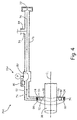
- FIG. 4 is a schematic view of bearing damping system 70A.
- FIG. 4 shows shaft 38, pump 72, fluid 74, first conduit 76, variable position valve 78A, diaphragm 80, second conduit 82, third conduit 84, and sensing line 86.
- Pump 72 contains fluid 74 and is connected to first conduit 76.
- First conduit 76 leads away from pump 72 and connects to variable position valve 78A.
- Variable position valve 78A includes diaphragm 80.
- Second conduit 82 leads away from variable position valve 78A, passes through bearing housing 60, and terminates in fluid compartment 66.
- Third conduit 84 branches from first conduit 76 and leads to a component of gas turbine engine 10.
- Sensing line 86 is connected on one end to second conduit 82 and to the backside of diaphragm 80 on another end.
- fluid 74 is pumped through first conduit 76 by pump 72.
- Pump 72 produces a continuous flow of fluid 74 through bearing damping system 70A.
- the pressure of fluid 74 in first conduit 76 can depend on the diameter of first conduit 76, flow rate of fluid 74, viscosity of fluid 74, and the temperature of fluid 74.
- Fluid 74 can flow into third conduit 84 which takes fluid 74 to other components of gas turbine engine 10 that require fluid 74 (e.g., for lubrication purposes). Fluid 74 that does not enter third conduit 84 enters variable position valve 78A.
- Variable position valve 78A is disposed between first conduit 76 and second conduit 82.
- Variable position valve 78A has a plurality of open positions. Each open position either contracts or expands a flow area in variable position valve 78A for fluid 74 to pass through in order to enter second conduit 82. The flow of fluid 74 through variable position valve 78A is reduced when fluid 74 passes through a flow area having a smaller diameter than first conduit 76. Thus the flow of fluid 74 in second conduit 82 can be controlled by alternating variable position valve 78A between the plurality of open positions.
- Variable position valve 78A as shown in in FIG. 4 is a pressure sensing valve that includes diaphragm 80, which regulates flow through valve 78A.
- Diaphragm 80 is pressure actuated. That is, if a pressure on the back side of diaphragm 80 exceeds a threshold value, then diaphragm 80 is actuated to constrict the flow area of variable position valve 78A through which fluid 74 can pass. If, on the other hand, the pressure on the back side of diaphragm 80 is less than a threshold value, then diaphragm 80 is actuated to expand the flow area that fluid 74 can pass through in variable position valve 78A. In other embodiments of variable position valve 78A diaphragm 80 can be replaced with a poppet.
- Sensing line 86 can be connected to second conduit 82 or fluid compartment 66 on one end and is connected to the back side of diaphragm 80 on the other end.
- the fluid pressure in either second conduit 82 or fluid compartment 66 will then be communicated to diaphragm 80 which is actuated as described above to increase or decrease the flow area in variable position valve 78A for fluid 74 to flow through.
- variable position valve 78A After passing through variable position valve 78A, fluid 74 enters second conduit 82. Fluid 74 flows through second conduit 82 into fluid compartment 66. As stated above, variable position valve 78A controls the flow of fluid 74 that is fed into second conduit 82 and fluid compartment 66. In controlling the flow of fluid 74 variable position valve 78A can also control the pressure of fluid 74 downstream from valve 78A. For example the flow of fluid 74 can be increased so as to increase the pressure of fluid 74 fed into fluid compartment 66.
- the flow of fluid 74 can also be decreased in order to decrease the volume of fluid 74 within fluid compartment 66.
- incoming fluid will not replace fluid that exited fluid compartment 66 at a fast enough rate to maintain the fill volume of fluid compartment 66.
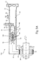
- FIG. 5A is a schematic view of bearing damping system 70B including variable position valve 78B.
- Variable position valve 78B includes multiple orifice sleeve 88 having first plurality of orifices 94, second plurality of orifices 95, and outlet 96. Poppet 91 and spring 100 are also shown. Combustor bleed gas 75 is also shown.
- Sleeve 88 is fastened within first conduit 76.
- sleeve 88 includes first and second pluralities of orifices 94 and 95.
- each plurality of orifices is formed from a group of three orifices. In other embodiments each plurality of orifices 94 and 95 can include other plural numbers of orifices.
- Outlet 96 is formed in an end of sleeve 88 near second conduit 82.
- Poppet 91 is solid and is disposed within sleeve 88.
- Spring 100 is attached to sleeve 88 near outlet 96 and to poppet 91.
- Sensing line 86 runs from second conduit 82 to the backside of poppet 91.
- variable position valve 78B In operation, fluid 74 passes through bearing damping system 70B in much the same way as in bearing damping system 70A.
- variable position valve 78B In the embodiment shown in FIG. 5 , variable position valve 78B has two open positions and one closed position. Variable position valve 78B is fully open in the first open position. This is shown in FIG. 5A as poppet 91 is not blocking any of first or second plurality of orifices 94 or 95. Thus, the flow area through sleeve 88 is at a maximum.
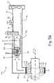
- FIG. 5B shows variable position valve 78B in the second open position.
- poppet 91 blocks first plurality of orifices 94.
- the feed pressure and flow of fluid 74 will be less than the pressure and flow of fluid 74 in first conduit 76. This is because the flow area through sleeve 88 is decreased.
- variable position valve 78B is in the closed position, then second plurality of orifices 95 will be blocked by poppet 91.
- the feed pressure and flow of fluid 74 inside fluid compartment 66 can be controlled by adjusting the position of poppet 91 with respect to first and second plurality of orifices 94 and 95.
- variable position valve 78B additional pluralities of orifices can be included on sleeve 88 in order to increase the number of possible open positions in variable position valve 78B.
- the orifices forming first and second pluralities of orifices 94 and 95 can be of uniform or differing sizes.
- orifices can be replaced with one or more elongated openings in sleeve 88. In that case, poppet 91 can be actuated along the openings to continuously increase or decrease the flow area through sleeve 88.
- Variable position valve 78B can be actuated in many different ways such as in response to an operating condition of gas turbine engine 10. For example, actuation of variable position valve 78B can be driven in response to a sensed pressure of combustor bleed gas 75 in combustor 14. A pressure increase in combustor 14 can lead to a higher rate of rotation in low pressure turbine 36 which will cause low pressure shaft 38 to rotate faster and potentially cause increased vibrations.
- An increase in pressure of combustor bleed gas 75 can be communicated to poppet 91 through sensing line 86, which is connected to combustor 14 and the backside of poppet 91.
- the pressure of combustor bleed gas 75 can cause poppet 91 to decrease the flow area through sleeve 88 by blocking the orifices in sleeve 88.
- spring 100 is compressed. If the pressure of combustor bleed gas 75 decreases, then spring 100 will expand and cause poppet 91 to be actuated to increase flow area through sleeve 88 by blocking fewer orifices.
- variable position valve 78B can be configured to be actuated in order to adjust the feed pressure into fluid compartment 66 to maintain optimal feed pressure and fill volume in fluid compartment 66.
- poppet 91 can be actuated by a threaded screw and bolt or by a magnet that is configured to generate a sufficient magnetic force to actuate poppet 91.
- FIG. 6A is a schematic view of bearing damping system 70C.
- Bearing damping system 70C includes many of the same features as bearing damping system 70B. One difference is variable position valve 78C, which includes plate 89. Plate 89 is a solid plate.
- Bearing damping system 70C also includes piston 92 plate, which is connected to plate 89. Piston 92 plate is also connected to spring 100.
- variable position valve 78C can be actuated to one of a plurality of positions ranging from a fully open position as illustrated in FIG. 6A to a fully closed position where plate 89 blocks flow of fluid 74 through variable position valve 78C.
- actuating plate 89 decreases or increases the flow area through variable position valve 78C, which determines the feed pressure of fluid 74 into fluid chamber 66.
- Plate 89 can be actuated as described above with respect to poppet 91.
- sensing line 86 communicates fluid pressure in second conduit 82 to the backside of plate 89.
- plate 89 and piston plate 92 are actuated down. This causes plate 89 to be disposed between first conduit 76 and second conduit 82.
- variable position valve 78C can, additionally, be actuated in a manner similar to that described above with respect to variable position valve 78B.
- plate 89 can be actuated in response to a sensed pressure in combustor 14 as described above with respect to bearing damping system 70B.
- FIG. 6B is a schematic view of bearing damping system 70C.
- FIG. 6B shows all of the same components as FIG. 6A .
- a portion of plate 89 is disposed between first conduit 76 and second conduit 82.
- the flow area through variable position valve 70C is decreased compared to the flow area though valve 70C shown in FIG. 6A .
- FIG. 7 is a schematic view of bearing damping system 70D.
- Bearing damping system 70D includes electronic engine controller 102, position channel 104, pressure sensor 106, pressure feedback channel 108, vibration sensor 110, stationary structure 112, vibration data channel 114, temperature sensor 116, temperature data channel 118, rotation sensor 120, and rotation data channel 122.
- Plate 89 is disposed within variable position valve 78C as described above with respect to FIGs. 6A and 6B .
- Electronic engine controller 102 is disposed within gas turbine engine 10 and is configured to receive and transmit data within bearing damping system 70D.
- Electronic engine controller 102 includes position channel 104, which communicates position commands to variable position valve 78C and receives feedback on the position of plate 89.
- Pressure sensor 106 is disposed upstream of variable position valve 78C and senses the pressure of fluid 74. The pressure data sensed by pressure sensor 106 is communicated to electronic engine controller 102 by pressure feedback channel 108.
- Vibration sensor 110 is mounted to stationary structure 112 and transmits vibration data to electronic engine controller 102 by vibration data channel 114.
- Temperature sensor 116 is disposed near fluid compartment 66 and communicates temperature data to electronic engine controller 102 by temperature data channel 118.
- Rotation sensor 120 is positioned near low pressure shaft 38 and communicates rotational data to electronic engine controller 102 by rotation data channel 122.
- plate 89 is actuated in response to a command generated by electronic engine controller 102.
- Plate 89 can be actuated in a manner similar to that described above with respect to FIGs 6A and 6B .
- Electronic engine controller 102 can also be used to actuate diaphragm 80 of bearing damping system 70A or poppet 91 of bearing damping system 70B described above.
- Electronic engine controller 102 can be programed to interpret vibration related parameters and send a command to actuate variable position valve 78A, 78B, or 78C into any of the open positions. Electronic engine controller 102 can also actuate variable position valve 78A, 78B, or 78C into a closed position. Electronic engine controller 102 can sense any one vibration related parameter individually or any combination of vibration related parameters discussed above simultaneously and issue an actuation command accordingly.
- Pressure sensor 106 can transmit pressure data of fluid 74 in first conduit 76 to electronic engine controller 102 by pressure feedback channel 104.
- Electronic engine controller 102 can compare that data to a programed schedule and send a position command to variable position valve 78C by position channel 104.
- the position command will cause variable position valve 78C to be actuated so as to produce an optimal feed pressure in second conduit 82 or fluid compartment 66.
- Position channel 104 can also communicate position feedback data to electronic engine controller 102 so that controller 102 will know what position variable position valve 78C is in.
- Pressure sensor 106 can also be disposed to be able to sense the pressure of fluid 74 in second conduit 82 or fluid compartment 66. If electronic engine controller 102 determines that the pressure at either location is too low, then electronic engine controller 102 can send a command to open variable position valve 78A, 78B, or 78C to a greater degree by contracting diaphragm 80, positioning poppet 91 to increase the flow area through sleeve 88, or retracting plate 89 to increase the flow area through valve 78C.
- electronic engine controller 102 can send a command to close variable position valve 78A, 78B, or 78C to a greater degree by expanding diaphragm 80, positioning poppet 91 to decrease flow through sleeve 88, or actuating plate 89 to decrease the flow area through valve 78C.
- Vibration sensor 110 is positioned on stationary structure 112. Vibration sensor 110 senses the extent to which stationary structure 112 vibrates during operation of gas turbine engine 10. Vibration sensor 110 can be an accelerometer. Vibration sensor 110 sends vibration data to electronic engine controller 102 by vibration data channel 114. If electronic engine controller 102 determines that stationary structure 112 is vibrating too much, then it can send a command to open or close variable position valve 78A, 78B, or 78C to a greater degree by contracting diaphragm 80 or positioning poppet 91 to increase or decrease flow through sleeve 88, or by actuating plate 89 to increase or decrease the flow area through variable position valve 78C.
- Temperature sensor 116 is disposed near fluid compartment 66. Temperature sensor 116 measures the temperature of fluid 74 inside fluid compartment 66. As stated above, the temperature of fluid 74 is relevant to its viscosity. Temperature sensor 116 sends temperature data to electronic engine controller 102 by temperature data channel 118. Electronic engine controller 102 can calculate the viscosity of fluid 74 based on fluid type and fluid 74's temperature. If electronic engine controller 102 determines that fluid 74's viscosity is inadequate to provide damping, then it can send a command to open or close variable position valve 78A, 78B, or 78C. This way fluid 74 supply pressure can be adjusted to compensate. Temperature sensor 116 can also be disposed so as to sense a temperature of fluid 74 in first conduit 76 or second conduit 82.
- Rotation sensor 120 is disposed near low pressure shaft 38. Rotation sensor 120 measures the rate of rotation of low pressure shaft 38.
- Low pressure shaft 38's rate of rotation can be relevant to bearing damping system 70A, 70B, 70C, or 70D in several different ways. For example, at startup of gas turbine engine 10, fluid in bearing damping system 70A, 70B, 70C, or 70D can be low. This can result from pump 72 being an engine driven pump. If pump 72 is engine driven, then fluid will not be pumped into bearing damping system 70A, 70B, 70C, or 70D when gas turbine engine 10 is shut down.
- electronic engine controller 102 senses that low pressure shaft 38 has begun to rotate based on data from rotation sensor 120, then it can send a command to open variable position valve 78A, 78B, or 78C to a greater degree by contracting diaphragm 80, positioning poppet 91 to increase the flow area through sleeve 88, or retracting plate 89 to increase the flow area through valve 78C. This way flow of fluid 74 will be at its greatest magnitude during engine start up.
- variable position valve 78A or 78B as described above to increase or decrease the flow of fluid 74 to dampen any vibrations associated with reaching the natural frequency of low pressure shaft 38. If bearing damping system 70A, 70B, 70C, or 70D is applied to high pressure shaft 40 these same principles can apply to it.
- FIG. 8 is a schematic view of bearing damping system 70E.
- Bearing damping system 70E includes many of the same components as bearing damping systems 70A, 70B, 70C, and 70D. Bearing damping system 70E, however, differs in several respects. For example, bearing damping system 70E includes variable position valve 78D and bypass line 83.
- variable position valve 78D can be adjusted to be one of a plurality of open positions ranging from fully open to closed.
- variable position valve 78D When variable position valve 78D is fully closed the flow of fluid 74 to fluid compartment 66 will be at a maximum.
- variable position valve 78D opens the flow area in valve 78D increases. This results in fluid 74 flowing through bypass line 83, which reduces the flow of fluid 74 into fluid compartment 66.
- Variable position valve 78D can be actuated in any of the manners described above with respect to variable position valves 78A-78C.
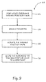
- FIG. 9 is a flow diagram showing method 124 for adjusting a stiffness fluid damped bearing system 70A, 70B, 70C, 70D, or 70E.
- method 124 includes pumping step 126, sensing step 128, actuating step 130, and routing step 132.
- pumping step 126 a fluid is pumped through first conduit 76 through variable position valve 78A, 78B, or 78C.
- sensing step 128 a parameter relating to a vibration rate of low pressure shaft 38 or high pressure shaft 40 is sensed. That parameter can be any parameter discussed above. That parameter can be sensed, for example, by the pressure of fluid 74 being communicated to the back side of variable position valves 78A, 78B, or 78C as described above.
- variable position valve 78A, 78B, or 78C is actuated as described above in response to the sensed parameter.
- routing step 132 fluid 74 is routed to fluid compartment 66.
- bearing damping system 70A, 70B, 70C, 70D, or 70E there are numerous reasons to use bearing damping system 70A, 70B, 70C, 70D, or 70E including the following non-limiting reasons.
- Bearing damping system 70A, 70B, 70C, 70D, or 70E works best when fluid 74 is at an optimum supply pressure.
- the volume of fluid 74 inside fluid compartment 66 can be maintained so as not to be operating under the soft or stiff conditions described above by using bearing damping system 70A, 70B, 70C, 70D, or 70E.
- bearing damping system 70A, 70B, 70C, 70D, or 70E can have pressure ranging from about 35 pounds per square inch differential (psid) to about 100 psid. That is, the volume of fluid 74 inside fluid compartment 66 can be maintained so as not to be operating under the soft or stiff conditions described above by using bearing damping system 70A, 70B, 70C, 70D, or 70E.
- variable position valves 78A, 78B, 78C, and 78D have multiple open positions the flow of fluid 74 into fluid compartment 66 can be fine-tuned to keep the fluid volume inside compartment 66 in the optimum range during operation of gas turbine engine 10.
- variable position valves 78A, 78B, 78C, or 78D can be actuated to increase the flow of fluid 74 if the fluid volume inside fluid compartment 66 falls below a certain threshold value causing the above referenced soft damper condition. The increase in flow into fluid compartment 66 will increase the fluid volume inside fluid compartment 66.
- variable position valves 78A, 78B, 78C, or 78D can be actuated to decrease the flow of fluid 74 if the fluid volume inside fluid compartment 66 rises above a certain threshold value causing the above referenced stiff damper condition.
- variable position valves 78A, 78B, 78C, or 78D can reduce the possibility of a blade rubbing event. Blade rubbing can occur if low pressure shaft 38 vibrates enough to cause the tip of one of the rotor blades to contact a stationary structure. This can damage the blade and require unscheduled maintenance on gas turbine engine 10.
- the rotor balance of gas turbine engine 10 can change over time. That is, if the LP spool or HP spool was initially balanced when it was installed into gas turbine engine 10, wear during operation can cause it to become unbalanced.
- the ability of bearing damping system 70A, 70B, 70C, 70D, or 70E to fine tune the pressure of fluid 74 in fluid compartment 66 however, can account for balance changes in the rotation of the spool and thus effectively dampen the vibrations.
- a bearing damping system can optionally include, additionally and/or alternatively, any one or more of the following features, configurations and/or additional components: a pump configured to pump a fluid through the system; a variable position valve connected to the pump by a first conduit and having a plurality of open positions each configured to generate different flows of the fluid downstream from the variable position valve; and a bearing assembly connected to the variable position valve by a second conduit and including: a bearing housing having an outer surface and an inner surface, the bearing housing configured to be attached to a stationary structure; a stationary bearing race having an outer surface and an inner surface and positioned within the bearing housing; a rotating bearing race having an outer surface and an inner surface spaced apart from the stationary bearing race and configured to be attached to a rotating component; a bearing element disposed between the inner surface of the stationary bearing race and the outer surface of the rotating g bearing race; and a fluid compartment defined by the space between the inner surface of the bearing housing and the outer surface of the stationary race and configured to receive the fluid from the second conduit
- the bearing damping system of the preceding paragraph can optionally include, additionally and/or alternatively, any one or more of the following features, configurations and/or additional components:
- variable position valve comprises: a pressure regulating valve that can have an adjustable diaphragm disposed between the first conduit and the second conduit.
- bearing system can include a plate movably disposed within the variable position valve to generate a plurality of flow areas through the variable position valve.
- variable position valve can include a sleeve disposed in the first conduit in which the sleeve can include a plurality of orifices and a poppet movably disposed within the sleeve and configured to regulate a flow area though the sleeve by blocking at least one orifice.
- variable position valve can be configured to restrict a flow of the fluid into the fluid compartment when a fluid supply pressure into the compartment exceeds a threshold pressure.
- variable position valve can be configured to increase a flow of the fluid when the fluid supply pressure into the fluid compartment falls below a threshold pressure.
- the system can further include a controller configured to monitor a parameter and actuate the variable position valve to maintain an optimum fluid pressure in the fluid compartment, wherein the parameter monitored by the controller is selected from the group consisting of: a stationary structure vibration rate, a component rotation rate, a fluid pressure in the first conduit, a fluid pressure in the second conduit, a fluid pressure in the fluid compartment, a fluid viscosity in the first conduit, a fluid viscosity in the second conduit, a fluid viscosity in the fluid compartment, a fluid temperature in the fluid compartment, a fluid temperature in the first conduit, a fluid temperature in the second conduit, and combinations thereof.
- the parameter monitored by the controller is selected from the group consisting of: a stationary structure vibration rate, a component rotation rate, a fluid pressure in the first conduit, a fluid pressure in the second conduit, a fluid pressure in the fluid compartment, a fluid viscosity in the first conduit, a fluid viscosity in the second conduit, a fluid viscosity in the fluid compartment, a fluid
- a further embodiment of the foregoing bearing damping system wherein the system can further include an accelerometer disposed on the stationary structure configured to measure the stationary structure vibration rate.
- a gas turbine engine can optionally include, additionally and/or alternatively, any one or more of the following features, configurations and/or additional components: a stationary section; a rotating section joined to a shaft; a bearing housing having a radially outer surface and a radially inner surface and attached to the stationary section of the gas turbine engine; a stationary bearing race having a radially outer surface and a radially inner surface and spaced radially inward from the bearing housing; a rotating bearing race having a radially outer surface and a radially inner surface and spaced radially inward from the stationary bearing race and attached to the shaft; a bearing element disposed between the radially inner surface of the stationary bearing race and the radially outer surface of the rotating bearing race; a fluid compartment defined by the space between the radially inner surface of the bearing housing and the radially outer surface of the stationary race; a pump configured to pump a fluid into the fluid compartment; and a variable position valve having a plurality of open positions configured to
- the gas turbine engine of the preceding paragraph can optionally include, additionally and/or alternatively, any one or more of the following features, configurations and/or additional components:
- variable position valve can be positioned between the pump and the fluid chamber.
- variable position valve can regulate a flow of the fluid by increasing or decreasing a size of a valve flow area
- variable position can increase the size of the valve flow area when the fluid supply pressure into the fluid compartment falls below a threshold pressure.
- variable position valve can decrease the size of the valve flow area when the fluid supply pressure into the fluid compartment exceeds a threshold pressure.
- gas turbine engine can further include a controller that actuates the variable position valve based on a parameter selected from the group consisting of: a stationary structure vibration rate, a shaft rotation rate, a fluid pressure between the pump and the variable position valve, a fluid pressure between the variable position pump and the fluid compartment, a fluid pressure in the fluid compartment, a fluid viscosity, a fluid temperature, and combinations thereof.
- a controller that actuates the variable position valve based on a parameter selected from the group consisting of: a stationary structure vibration rate, a shaft rotation rate, a fluid pressure between the pump and the variable position valve, a fluid pressure between the variable position pump and the fluid compartment, a fluid pressure in the fluid compartment, a fluid viscosity, a fluid temperature, and combinations thereof.
- a further embodiment of the foregoing gas turbine engine, wherein the stationary structure vibration rate can be measured by an accelerometer.
- bearing element can be a ball or a roller.
- a method of adjusting a stiffness of a fluid damped bearing can optionally include, additionally and/or alternatively, any one or more of the following steps: pumping a fluid through a variable position valve having a plurality of open positions; sensing a parameter relating to a vibration rate of a rotating component; actuating a variable position valve in response to the sensed parameter to control a flow of a fluid; and routing the fluid from the variable position valve to a fluid compartment formed between a bearing housing and a stationary race of the fluid damped bearing.
- the method of the preceding paragraph can optionally include, additionally and/or alternatively, any one or more of the following steps or features:
- the parameter can be selected from the group consisting of: a stationary structure vibration rate, a component rate of rotation, a fluid viscosity, a fluid temperature, a fluid pressure, and combinations thereof.
- a further embodiment of the foregoing method wherein the method can include the step of restricting a flow of the fluid into the fluid damped bearing when the pressure inside the compartment exceeds a threshold pressure.
- a further embodiment of the foregoing method wherein the method can include the step of increasing the flow of the fluid when the pressure falls below a threshold feed pressure.
Landscapes
- Engineering & Computer Science (AREA)
- General Engineering & Computer Science (AREA)
- Mechanical Engineering (AREA)
- Physics & Mathematics (AREA)
- Acoustics & Sound (AREA)
- Aviation & Aerospace Engineering (AREA)
- Support Of The Bearing (AREA)
- Magnetic Bearings And Hydrostatic Bearings (AREA)
Abstract
Description
- Gas turbine engines can include fluid damped bearings to help maintain vibration and displacement of rotating components within acceptable limits. Typically, these fluid damped bearings are fed oil from the engine oil system and accept the oil at a pressure generated by the system. Typical systems regulate fluid flow to the fluid damped bearing with a valve that switches between on and off positions. In some cases, however, alternating between on and off positions exclusively can cause the oil flow rate to stray from an optimal flow rate to a rate that is either too high or too low. Either condition can lead to undesired vibration and displacement of rotating components during operation of the gas turbine engine. There is, accordingly, a need for a fluid damped bearing system that can help maintain an optimum flow of fluid to the fluid damped bearing during operation of the gas turbine engine.
- According to one embodiment of this disclosure a bearing damping system includes a pump configured to pump a fluid through the system. The system further includes a variable position valve connected to the pump by a first conduit and having a plurality of open positions each configured to generate a different flow in the fluid downstream from the variable position valve. The system also includes a bearing assembly connected to the variable position valve by a second conduit. The bearing assembly includes a bearing housing having an outer surface and an inner surface. The bearing housing is configured to be attached to a stationary structure. The bearing assembly also includes a stationary bearing race having an outer surface and an inner surface and is positioned within the bearing housing. The bearing assembly also includes a rotating bearing race having an outer surface and an inner surface spaced apart from the stationary bearing race and configured to be attached to a rotating component. A bearing element is disposed between the inner surface of the stationary bearing race and the outer surface of the rotating race. A fluid compartment is defined by the space between the inner surface of the bearing housing and the outer surface of the stationary race and is configured to receive the fluid from the second conduit.
- According to another embodiment of this disclosure a gas turbine engine includes a stationary section and a rotating section joined to a shaft. The gas turbine engine also includes a bearing housing having a radially outer surface and a radially inner surface. The bearing housing is attached to the stationary section of the gas turbine engine. A stationary bearing race having a radially outer surface and a radially inner surface is spaced radially inward from the bearing housing. A rotating bearing race having a radially outer surface and a radially inner surface is spaced radially inward from the stationary bearing race and attached to the shaft. A bearing element is disposed between the radially inner surface of the stationary bearing race and the radially outer surface of the rotating bearing race. A fluid compartment is defined by the space between the radially inner surface of the bearing housing and the radially outer surface of the stationary race. The gas turbine engine also includes a pump configured to pump a fluid into the fluid compartment. The gas turbine engine further includes a variable position valve disposed between the fluid compartment and the pump. The variable position valve has a plurality of open positions configured to generate a plurality of fluid flows within the fluid compartment.
- According to yet another embodiment of the disclosure a method of adjusting a stiffness of a fluid damped bearing includes the step of pumping a fluid through a variable position valve having a plurality of open positions. The method further includes the step of sensing a parameter relating to a vibration rate of a rotating component. The method also includes the step of actuating a variable position valve in response to the sensed parameter to control a flow of a fluid. The method additionally includes the step of routing the fluid from the variable position valve to a fluid compartment formed between a bearing housing and a stationary race of the fluid damped bearing.
-
-
FIG. 1 is a sectional view of a gas turbine engine. -
FIG. 2 is a perspective sectional view of a ball bearing including a fluid damper compartment. -
FIG. 3 is a sectional view of the ball bearing taken along line 2-2 fromFIG. 2 . -
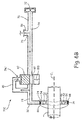
FIG. 4 is a schematic view of a bearing damping system with a pressure regulating valve regulating fluid flow. -
FIG. 5A is a schematic view of a bearing damping system with a variable position valve regulating fluid flow in a first open position. -
FIG. 5B is a schematic view of a bearing damping system with the variable position valve ofFIG. 5A in a second open position. -
FIG. 6A is a schematic view of a bearing damping system with an alternative variable position valve regulating fluid flow in a first open position. -
FIG. 6B is a schematic view of a bearing damping system with the variable position valve ofFIG. 6A in a second open position. -
FIG. 7 is a schematic view of a bearing damping system with an electronically controlled variable position valve. -
FIG. 8 is a schematic view of an alternative bearing damping system having a valve disposed on a bypass line regulating fluid flow. -
FIG. 9 is a flow diagram showing a method of adjusting a stiffness of a fluid damped bearing. - This disclosure is directed towards fluid damped bearings. More particularly, this disclosure is directed towards regulating the fluid pressure in fluid damped bearings.
-
FIG. 1 is a sectional view ofgas turbine engine 10. Gas turbine engine (or turbine engine) 10 includes a power core withcompressor section 12,combustor 14 andturbine section 16 arranged in flow series betweenupstream inlet 18 anddownstream exhaust 20.Compressor section 12 andturbine section 16 are arranged into a number of alternating stages of rotor airfoils (or blades) 22 and stator airfoils (or vanes) 24. - In the turbofan configuration of
FIG. 1 ,propulsion fan 26 is positioned inbypass duct 28, which is coaxially oriented about the engine core along centerline (or turbine axis) CL. An open-rotor propulsion stage 26 may also be provided, withturbine engine 10 operating as a turboprop or unducted turbofan engine. Alternatively,fan rotor 26 andbypass duct 28 may be absent, withturbine engine 10 configured as a turbojet or turboshaft engine, or an industrial gas turbine.Gas turbine engine 10 can also include geared architecture such as a fan drive gear system. - In the two-spool, high bypass configuration of
FIG. 1 ,compressor section 12 includes low pressure compressor (LPC) 30 and high pressure compressor (HPC) 32, andturbine section 16 includes high pressure turbine (HPT) 34 and low pressure turbine (LPT) 36.Low pressure compressor 30 is rotationally coupled tolow pressure turbine 36 via low pressure (LP)shaft 38, forming the LP spool or low spool.High pressure compressor 32 is rotationally coupled tohigh pressure turbine 34 via high pressure (HP)shaft 40, forming the HP spool or high spool. - Flow F at
inlet 18 divides into primary (core) flow FP and secondary (bypass) flow FS downstream offan rotor 26. Primary flow FP is compressed inlow pressure compressor 30 andhigh pressure compressor 32, and then mixed with fuel incombustor 14 and ignited to generate hot combustion gas. The combustion gas expands to provide rotational energy inhigh pressure turbine 34 andlow pressure turbine 36, drivinghigh pressure compressor 32 andlow pressure compressor 30, respectively. Expanded combustion gases exit through exhaust section (or exhaust nozzle) 20, which can be shaped or actuated to regulate the exhaust flow and improve thrust performance. -
Low pressure shaft 38 andhigh pressure shaft 40 are mounted coaxially about centerline CL, and rotate at different speeds. Fan rotor (or other propulsion stage) 26 is rotationally coupled tolow pressure shaft 38. Each shaft is associated with at least one bearing such as dampedball bearing 42 or dampedroller bearing 44. - Turbine efficiency and performance depends on the overall pressure ratio, defined by the total pressure at
inlet 18 as compared to the exit pressure ofcompressor section 12, for example at the outlet ofhigh pressure compressor 32, enteringcombustor 14. -
FIG. 2 is a perspective sectional view ofdamped ball bearing 42. AlthoughFIG. 2 shows dampedball bearing 42, the concepts described below are equally applicable todamped roller bearing 44.FIG. 2 includesrotating race 46, which includes rotating race radiallyinner surface 48 and rotating race radiallyouter surface 50; bearingelement 52,stationary race 54, which includes stationary race radiallyinner surface 56 and stationary race radiallyouter surface 58; bearinghousing 60, which includes bearing housing radiallyinner surface 62 and bearing housing radiallyouter surface 64; andfluid compartment 66. -
Low pressure shaft 38 defines a central rotational axis ofgas turbine engine 10. As stated above,low pressure shaft 38 drives rotation ofpropulsion fan 26,low pressure compressor 30, andlow pressure turbine 36 which define the LP spool. Althoughlow pressure shaft 38 is depicted inFIG. 2 , this description can also apply tohigh pressure shaft 40 which drives rotation ofhigh pressure compressor 32 andhigh pressure turbine 34 which define the HP spool.Damped ball bearing 42 surroundslow pressure shaft 38.Damped ball bearing 42 helps to facilitate rotation oflow pressure shaft 38. - Rotating
race 46 of dampedball bearing 42 is annularly shaped and circumscribeslow pressure shaft 38. Rotatingrace 46 includes rotating race radiallyinner surface 48 and rotating race radiallyouter surface 50.Low pressure shaft 38 is joined to rotating raceinner surface 48. Rotating race radiallyouter surface 50 interfaces with bearingelement 52. As depicted inFIG. 2 , bearingelement 52 is a ball but in otherembodiments bearing element 52 can be a cylindrical roller or a tapered roller bearing. -
Stationary race 54 of dampedball bearing 42 circumscribes and is spaced apart from rotatingrace 46.Stationary race 54 includes radiallyinner surface 56 and radiallyouter surface 58. Stationary race radiallyinner surface 56 is spaced apart from rotating race radiallyouter surface 50 and bearingelement 52 is disposed therebetween. - Bearing
housing 60, of dampedball bearing 42, circumscribesstationary race 54 and includes bearing housing radiallyinner surface 62 and bearing housing radiallyouter surface 64. Bearing housing radiallyinner surface 62 is joined to stationary race radiallyouter surface 58. A space is formed between bearing housing radiallyinner surface 62 and stationary race radiallyouter surface 58 which definesfluid compartment 66. Bearing housing radiallyouter surface 64 is joined to a non-rotating stationary structure ofgas turbine engine 10. -
FIG. 3 is a sectional view ofdamped ball bearing 42 taken along line 2-2 fromFIG. 2. FIG. 3 additionally illustratesradial extensions 68.Radial extensions 68 extend from the axial ends of stationary race radiallyouter surface 58.Radial extensions 68 are joined to bearing housing radiallyinner surface 62 and sealfluid compartment 66. In other embodiments of dampedball bearing 42radial extensions 68 can be replaced with piston rings or O-rings. - In operation,
low pressure shaft 38 rotates as core air flow flows throughgas turbine engine 10. Rotatingrace 46 rotates along withlow pressure shaft 38. The rotation is facilitated by bearingelements 52.Bearing elements 52 also help to keeplow pressure shaft 38 in a proper position because they are sized to fit betweenrotating race 46 andstationary race 54 so as to maintain contact with bothraces - As
low pressure shaft 38 rotates, it can vibrate and impart relatively strong forces radially outward from the central axis ofgas turbine engine 10. These forces are transmitted radially outward to rotatingrace 46. The forces are then transmitted radially outward to bearingelements 52. From bearingelements 52, the forces are transmitted radially outward tostationary race 54. -
Fluid compartment 66 is filled with a fluid such as engine oil. The fluid is typically pressurized and has a low viscosity. As an example, engine oil can be supplied tofluid compartment 66 at a temperature ranging from approximately 93.3 degrees Celsius (200 degrees Fahrenheit) to approximately 140.5 degrees Celsius (285 degrees Fahrenheit). At these temperatures the viscosity of the oil can range from approximately 5.8 centistokes to approximately 2.8 centistokes.Fluid 74 influid compartment 66 acts to dampen the vibrational forces described above. The damping effect is generated, in part, by the fluid influid compartment 66 being squeezed from one location incompartment 66 to another asstationary race 54 translates towards bearinghousing 60 due to the vibration oflow pressure shaft 38. As a result of the damping effect provided by the fluid, the severity of the vibrational forces projecting radially outward to bearinghousing 60 are lessened. As a result, a less severe vibrational force is translated radially outward from bearinghousing 60 to other structures ingas turbine engine 10 and the degree to whichlow pressure shaft 38 vibrates is also lessened. - The degree to which fluid in
fluid compartment 66 dampens vibrations is a function of many factors. One factor is the amount offluid 74 influid compartment 66. The degree to whichfluid compartment 66 is filled withfluid 74 can be referred to as the fill volume offluid compartment 66. The amount offluid 74 influid compartment 66 is a function of the rate of flow offluid 74 intocompartment 66 as compared to the rate of flow offluid 74 out ofcompartment 66. The flow rate offluid 74 intofluid compartment 66 is largely driven by the pressure offluid 74 supplied tofluid compartment 66. This pressure can be referred to as a feed pressure. - If the feed pressure is too low, then the amount of
fluid 74 influid compartment 66 will not be able to sufficiently absorb the vibrational forces that are transmitted to it. These conditions give rise to a soft damper. If, on the other hand, the feed pressure offluid 74 is too high, then thefluid compartment 66 will be over full and vibrational forces will be able to easily translate through the fluid to bearinghousing 60. These conditions give rise to a stiff damper. A fluid feed pressure should be maintained to keepfluid compart 66 at an optimum fill volume that is between the soft and stiff damper conditions. - Fluid viscosity is another factor that is relevant to the fluid's ability to dampen vibrations. The more viscous the fluid is the less likely it is to be displaced too easily by vibrational forces. If the fluid's viscosity is too high however, such that
fluid 74 does not move around influid compartment 66, then the vibrational forces will translate through it. Fluid viscosity can also be reduced during operation oflow pressure shaft 38 if the fluid supply temperature is elevated. -
FIG. 4 is a schematic view of bearing dampingsystem 70A.FIG. 4 showsshaft 38, pump 72,fluid 74,first conduit 76,variable position valve 78A,diaphragm 80,second conduit 82,third conduit 84, and sensingline 86. -
Pump 72 containsfluid 74 and is connected tofirst conduit 76.First conduit 76 leads away frompump 72 and connects tovariable position valve 78A.Variable position valve 78A includesdiaphragm 80.Second conduit 82 leads away fromvariable position valve 78A, passes through bearinghousing 60, and terminates influid compartment 66.Third conduit 84 branches fromfirst conduit 76 and leads to a component ofgas turbine engine 10. Sensingline 86 is connected on one end tosecond conduit 82 and to the backside ofdiaphragm 80 on another end. - In operation,
fluid 74 is pumped throughfirst conduit 76 bypump 72.Pump 72 produces a continuous flow offluid 74 through bearing dampingsystem 70A. The pressure offluid 74 infirst conduit 76 can depend on the diameter offirst conduit 76, flow rate offluid 74, viscosity offluid 74, and the temperature offluid 74.Fluid 74 can flow intothird conduit 84 which takesfluid 74 to other components ofgas turbine engine 10 that require fluid 74 (e.g., for lubrication purposes).Fluid 74 that does not enterthird conduit 84 entersvariable position valve 78A. -
Variable position valve 78A is disposed betweenfirst conduit 76 andsecond conduit 82.Variable position valve 78A has a plurality of open positions. Each open position either contracts or expands a flow area invariable position valve 78A forfluid 74 to pass through in order to entersecond conduit 82. The flow offluid 74 throughvariable position valve 78A is reduced when fluid 74 passes through a flow area having a smaller diameter thanfirst conduit 76. Thus the flow offluid 74 insecond conduit 82 can be controlled by alternatingvariable position valve 78A between the plurality of open positions. -
Variable position valve 78A as shown in inFIG. 4 is a pressure sensing valve that includesdiaphragm 80, which regulates flow throughvalve 78A.Diaphragm 80 is pressure actuated. That is, if a pressure on the back side ofdiaphragm 80 exceeds a threshold value, then diaphragm 80 is actuated to constrict the flow area ofvariable position valve 78A through whichfluid 74 can pass. If, on the other hand, the pressure on the back side ofdiaphragm 80 is less than a threshold value, then diaphragm 80 is actuated to expand the flow area that fluid 74 can pass through invariable position valve 78A. In other embodiments ofvariable position 80 can be replaced with a poppet.valve 78A diaphragm - Communication of the fluid pressure to the back side of
diaphragm 80 is facilitated by sensingline 86. Sensingline 86 can be connected tosecond conduit 82 orfluid compartment 66 on one end and is connected to the back side ofdiaphragm 80 on the other end. The fluid pressure in eithersecond conduit 82 orfluid compartment 66 will then be communicated to diaphragm 80 which is actuated as described above to increase or decrease the flow area invariable position valve 78A forfluid 74 to flow through. - After passing through
variable position valve 78A,fluid 74 enterssecond conduit 82.Fluid 74 flows throughsecond conduit 82 intofluid compartment 66. As stated above,variable position valve 78A controls the flow offluid 74 that is fed intosecond conduit 82 andfluid compartment 66. In controlling the flow offluid 74variable position valve 78A can also control the pressure offluid 74 downstream fromvalve 78A. For example the flow offluid 74 can be increased so as to increase the pressure offluid 74 fed intofluid compartment 66. - The flow of
fluid 74 can also be decreased in order to decrease the volume offluid 74 withinfluid compartment 66. By decreasing the flow offluid 74 intofluid compartment 66 the fluid volume insidecompartment 66 will decrease becausefluid 74 exitsfluid compartment 66 during operation ofgas turbine engine 10. Thus, if the flow offluid 74 is restricted, then incoming fluid will not replace fluid that exitedfluid compartment 66 at a fast enough rate to maintain the fill volume offluid compartment 66. -
FIG. 5A is a schematic view of bearing dampingsystem 70B includingvariable position valve 78B.Variable position valve 78B includesmultiple orifice sleeve 88 having first plurality oforifices 94, second plurality oforifices 95, andoutlet 96.Poppet 91 andspring 100 are also shown. Combustor bleedgas 75 is also shown. -
Sleeve 88 is fastened withinfirst conduit 76. As stated abovesleeve 88 includes first and second pluralities oforifices orifices Outlet 96 is formed in an end ofsleeve 88 nearsecond conduit 82.Poppet 91 is solid and is disposed withinsleeve 88.Spring 100 is attached tosleeve 88 nearoutlet 96 and topoppet 91. Sensingline 86 runs fromsecond conduit 82 to the backside ofpoppet 91. - In operation, fluid 74 passes through bearing damping
system 70B in much the same way as in bearing dampingsystem 70A. One difference between the two systems is that the feed pressure offluid 74 is controlled byvariable position valve 78B in bearing dampingsystem 70B. In the embodiment shown inFIG. 5 ,variable position valve 78B has two open positions and one closed position.Variable position valve 78B is fully open in the first open position. This is shown inFIG. 5A aspoppet 91 is not blocking any of first or second plurality oforifices sleeve 88 is at a maximum. -
FIG. 5B showsvariable position valve 78B in the second open position. As shown, in the secondopen position poppet 91 blocks first plurality oforifices 94. As a result, the feed pressure and flow offluid 74 will be less than the pressure and flow offluid 74 infirst conduit 76. This is because the flow area throughsleeve 88 is decreased. Ifvariable position valve 78B is in the closed position, then second plurality oforifices 95 will be blocked bypoppet 91. As can be understood from the above discussion, the feed pressure and flow offluid 74 insidefluid compartment 66 can be controlled by adjusting the position ofpoppet 91 with respect to first and second plurality oforifices - In other embodiments of
variable position valve 78B additional pluralities of orifices can be included onsleeve 88 in order to increase the number of possible open positions invariable position valve 78B. Additionally, the orifices forming first and second pluralities oforifices sleeve 88. In that case,poppet 91 can be actuated along the openings to continuously increase or decrease the flow area throughsleeve 88. -
Variable position valve 78B can be actuated in many different ways such as in response to an operating condition ofgas turbine engine 10. For example, actuation ofvariable position valve 78B can be driven in response to a sensed pressure of combustor bleedgas 75 incombustor 14. A pressure increase incombustor 14 can lead to a higher rate of rotation inlow pressure turbine 36 which will causelow pressure shaft 38 to rotate faster and potentially cause increased vibrations. - An increase in pressure of combustor bleed
gas 75 can be communicated topoppet 91 throughsensing line 86, which is connected to combustor 14 and the backside ofpoppet 91. The pressure of combustor bleedgas 75 can causepoppet 91 to decrease the flow area throughsleeve 88 by blocking the orifices insleeve 88. Aspoppet 91 is actuated to block the orifices,spring 100 is compressed. If the pressure of combustor bleedgas 75 decreases, then spring 100 will expand and causepoppet 91 to be actuated to increase flow area throughsleeve 88 by blocking fewer orifices. - Based on the correlation of the pressure sensed in
combustor 14 and the rotation oflow pressure shaft 38,variable position valve 78B can be configured to be actuated in order to adjust the feed pressure intofluid compartment 66 to maintain optimal feed pressure and fill volume influid compartment 66. - In addition to
spring 100actuating poppet 91 ofvariable position valve 78B,poppet 91 can be actuated by a threaded screw and bolt or by a magnet that is configured to generate a sufficient magnetic force to actuatepoppet 91. -
FIG. 6A is a schematic view of bearing dampingsystem 70C. Bearing dampingsystem 70C includes many of the same features as bearing dampingsystem 70B. One difference isvariable position valve 78C, which includesplate 89.Plate 89 is a solid plate. Bearing dampingsystem 70C also includespiston 92 plate, which is connected to plate 89.Piston 92 plate is also connected tospring 100. - In operation,
variable position valve 78C can be actuated to one of a plurality of positions ranging from a fully open position as illustrated inFIG. 6A to a fully closed position whereplate 89 blocks flow offluid 74 throughvariable position valve 78C. Thus, actuatingplate 89 decreases or increases the flow area throughvariable position valve 78C, which determines the feed pressure offluid 74 intofluid chamber 66.Plate 89 can be actuated as described above with respect topoppet 91. As shown inFIG. 6A sensing line 86 communicates fluid pressure insecond conduit 82 to the backside ofplate 89. As the pressure increases,plate 89 andpiston plate 92 are actuated down. This causesplate 89 to be disposed betweenfirst conduit 76 andsecond conduit 82. As the pressure insecond conduit 82 increase,spring 100 is compressed. If the pressure communicated by sensingline 86 decreases, then spring 100 will not remain compressed andpiston plate 92 as well asplate 89 will be actuated up so as to increase the flow area throughvariable position valve 78C.Variable position valve 78C can, additionally, be actuated in a manner similar to that described above with respect tovariable position valve 78B. For example,plate 89 can be actuated in response to a sensed pressure incombustor 14 as described above with respect to bearing dampingsystem 70B. -
FIG. 6B is a schematic view of bearing dampingsystem 70C.FIG. 6B shows all of the same components asFIG. 6A . As shown, a portion ofplate 89 is disposed betweenfirst conduit 76 andsecond conduit 82. Thus, the flow area throughvariable position valve 70C is decreased compared to the flow area thoughvalve 70C shown inFIG. 6A . -
FIG. 7 is a schematic view of bearing dampingsystem 70D. Bearing dampingsystem 70D includeselectronic engine controller 102,position channel 104,pressure sensor 106,pressure feedback channel 108,vibration sensor 110,stationary structure 112,vibration data channel 114,temperature sensor 116,temperature data channel 118,rotation sensor 120, androtation data channel 122. -
Plate 89 is disposed withinvariable position valve 78C as described above with respect toFIGs. 6A and6B .Electronic engine controller 102 is disposed withingas turbine engine 10 and is configured to receive and transmit data within bearing dampingsystem 70D.Electronic engine controller 102 includesposition channel 104, which communicates position commands tovariable position valve 78C and receives feedback on the position ofplate 89.Pressure sensor 106 is disposed upstream ofvariable position valve 78C and senses the pressure offluid 74. The pressure data sensed bypressure sensor 106 is communicated toelectronic engine controller 102 bypressure feedback channel 108.Vibration sensor 110 is mounted tostationary structure 112 and transmits vibration data toelectronic engine controller 102 byvibration data channel 114.Temperature sensor 116 is disposed nearfluid compartment 66 and communicates temperature data toelectronic engine controller 102 bytemperature data channel 118.Rotation sensor 120 is positioned nearlow pressure shaft 38 and communicates rotational data toelectronic engine controller 102 byrotation data channel 122. - In operation,
plate 89 is actuated in response to a command generated byelectronic engine controller 102.Plate 89 can be actuated in a manner similar to that described above with respect toFIGs 6A and6B .Electronic engine controller 102 can also be used to actuatediaphragm 80 of bearing dampingsystem 70A orpoppet 91 of bearing dampingsystem 70B described above. -
Electronic engine controller 102 can be programed to interpret vibration related parameters and send a command to actuatevariable position valve Electronic engine controller 102 can also actuatevariable position valve Electronic engine controller 102 can sense any one vibration related parameter individually or any combination of vibration related parameters discussed above simultaneously and issue an actuation command accordingly. -
Pressure sensor 106 can transmit pressure data offluid 74 infirst conduit 76 toelectronic engine controller 102 bypressure feedback channel 104.Electronic engine controller 102 can compare that data to a programed schedule and send a position command tovariable position valve 78C byposition channel 104. The position command will causevariable position valve 78C to be actuated so as to produce an optimal feed pressure insecond conduit 82 orfluid compartment 66.Position channel 104 can also communicate position feedback data toelectronic engine controller 102 so thatcontroller 102 will know what positionvariable position valve 78C is in. -
Pressure sensor 106 can also be disposed to be able to sense the pressure offluid 74 insecond conduit 82 orfluid compartment 66. Ifelectronic engine controller 102 determines that the pressure at either location is too low, thenelectronic engine controller 102 can send a command to openvariable position valve diaphragm 80, positioningpoppet 91 to increase the flow area throughsleeve 88, or retractingplate 89 to increase the flow area throughvalve 78C. Alternatively, if the pressure is too high, thenelectronic engine controller 102 can send a command to closevariable position valve diaphragm 80, positioningpoppet 91 to decrease flow throughsleeve 88, or actuatingplate 89 to decrease the flow area throughvalve 78C. -
Vibration sensor 110 is positioned onstationary structure 112.Vibration sensor 110 senses the extent to whichstationary structure 112 vibrates during operation ofgas turbine engine 10.Vibration sensor 110 can be an accelerometer.Vibration sensor 110 sends vibration data toelectronic engine controller 102 byvibration data channel 114. Ifelectronic engine controller 102 determines thatstationary structure 112 is vibrating too much, then it can send a command to open or closevariable position valve diaphragm 80 orpositioning poppet 91 to increase or decrease flow throughsleeve 88, or by actuatingplate 89 to increase or decrease the flow area throughvariable position valve 78C. -
Temperature sensor 116 is disposed nearfluid compartment 66.Temperature sensor 116 measures the temperature offluid 74 insidefluid compartment 66. As stated above, the temperature offluid 74 is relevant to its viscosity.Temperature sensor 116 sends temperature data toelectronic engine controller 102 bytemperature data channel 118.Electronic engine controller 102 can calculate the viscosity offluid 74 based on fluid type andfluid 74's temperature. Ifelectronic engine controller 102 determines that fluid 74's viscosity is inadequate to provide damping, then it can send a command to open or closevariable position valve Temperature sensor 116 can also be disposed so as to sense a temperature offluid 74 infirst conduit 76 orsecond conduit 82. -
Rotation sensor 120 is disposed nearlow pressure shaft 38.Rotation sensor 120 measures the rate of rotation oflow pressure shaft 38.Low pressure shaft 38's rate of rotation can be relevant to bearing dampingsystem gas turbine engine 10, fluid in bearing dampingsystem pump 72 being an engine driven pump. Ifpump 72 is engine driven, then fluid will not be pumped into bearing dampingsystem gas turbine engine 10 is shut down. Ifelectronic engine controller 102 senses thatlow pressure shaft 38 has begun to rotate based on data fromrotation sensor 120, then it can send a command to openvariable position valve diaphragm 80, positioningpoppet 91 to increase the flow area throughsleeve 88, or retractingplate 89 to increase the flow area throughvalve 78C. This way flow offluid 74 will be at its greatest magnitude during engine start up. - In another example, if
low pressure shaft 38 has a known natural frequency, thenelectronic engine controller 102 can be programmed to actuatevariable position valve fluid 74 to dampen any vibrations associated with reaching the natural frequency oflow pressure shaft 38. If bearing dampingsystem high pressure shaft 40 these same principles can apply to it. -
FIG. 8 is a schematic view of bearing dampingsystem 70E. Bearing dampingsystem 70E includes many of the same components as bearing dampingsystems system 70E, however, differs in several respects. For example, bearing dampingsystem 70E includesvariable position valve 78D andbypass line 83. - In bearing damping
system 70E fluidpump 72 tofluid compartment 66 byfirst conduit 76.Bypass line 83 branches offfirst conduit 76 and leads tovariable position valve 78D and to other components ofgas turbine engine 10. - In operation, the flow area in
variable position valve 78D can be adjusted to be one of a plurality of open positions ranging from fully open to closed. Whenvariable position valve 78D is fully closed the flow offluid 74 tofluid compartment 66 will be at a maximum. Asvariable position valve 78D opens the flow area invalve 78D increases. This results influid 74 flowing throughbypass line 83, which reduces the flow offluid 74 intofluid compartment 66.Variable position valve 78D can be actuated in any of the manners described above with respect tovariable position valves 78A-78C. -
FIG. 9 is a flowdiagram showing method 124 for adjusting a stiffness fluid dampedbearing system method 124 includes pumpingstep 126, sensingstep 128, actuatingstep 130, androuting step 132. In pumping step 126 a fluid is pumped throughfirst conduit 76 throughvariable position valve low pressure shaft 38 orhigh pressure shaft 40 is sensed. That parameter can be any parameter discussed above. That parameter can be sensed, for example, by the pressure offluid 74 being communicated to the back side ofvariable position valves electronic engine controller 102. In actuatingstep 130variable position valve routing step 132fluid 74 is routed tofluid compartment 66. - There are numerous reasons to use bearing damping
system fluid 74, as described above, the damping effect of bearing dampingsystem system fluid 74 insidefluid compartment 66 can be maintained so as not to be operating under the soft or stiff conditions described above by using bearing dampingsystem example fluid 74 can have pressure ranging from about 35 pounds per square inch differential (psid) to about 100 psid. That is, the volume offluid 74 insidefluid compartment 66 can be maintained so as not to be operating under the soft or stiff conditions described above by using bearing dampingsystem - Because
variable position valves fluid 74 intofluid compartment 66 can be fine-tuned to keep the fluid volume insidecompartment 66 in the optimum range during operation ofgas turbine engine 10. For example,variable position valves fluid 74 if the fluid volume insidefluid compartment 66 falls below a certain threshold value causing the above referenced soft damper condition. The increase in flow intofluid compartment 66 will increase the fluid volume insidefluid compartment 66. Additionally,variable position valves fluid 74 if the fluid volume insidefluid compartment 66 rises above a certain threshold value causing the above referenced stiff damper condition. - Additionally, the ability of
variable position valves low pressure shaft 38 vibrates enough to cause the tip of one of the rotor blades to contact a stationary structure. This can damage the blade and require unscheduled maintenance ongas turbine engine 10. - Additionally, the rotor balance of
gas turbine engine 10 can change over time. That is, if the LP spool or HP spool was initially balanced when it was installed intogas turbine engine 10, wear during operation can cause it to become unbalanced. The ability of bearing dampingsystem fluid 74 influid compartment 66 however, can account for balance changes in the rotation of the spool and thus effectively dampen the vibrations. - The following are non-exclusive descriptions of possible embodiments of the present invention.
- A bearing damping system according to an exemplary embodiment of the invention can optionally include, additionally and/or alternatively, any one or more of the following features, configurations and/or additional components: a pump configured to pump a fluid through the system; a variable position valve connected to the pump by a first conduit and having a plurality of open positions each configured to generate different flows of the fluid downstream from the variable position valve; and a bearing assembly connected to the variable position valve by a second conduit and including: a bearing housing having an outer surface and an inner surface, the bearing housing configured to be attached to a stationary structure; a stationary bearing race having an outer surface and an inner surface and positioned within the bearing housing; a rotating bearing race having an outer surface and an inner surface spaced apart from the stationary bearing race and configured to be attached to a rotating component; a bearing element disposed between the inner surface of the stationary bearing race and the outer surface of the rotating g bearing race; and a fluid compartment defined by the space between the inner surface of the bearing housing and the outer surface of the stationary race and configured to receive the fluid from the second conduit.
- The bearing damping system of the preceding paragraph can optionally include, additionally and/or alternatively, any one or more of the following features, configurations and/or additional components:
- A further embodiment of the foregoing bearing damping system, wherein the variable position valve comprises: a pressure regulating valve that can have an adjustable diaphragm disposed between the first conduit and the second conduit.
- A further embodiment of the foregoing bearing damping system, wherein the bearing system can include a plate movably disposed within the variable position valve to generate a plurality of flow areas through the variable position valve.
- A further embodiment of the foregoing bearing damping system, wherein the variable position valve can include a sleeve disposed in the first conduit in which the sleeve can include a plurality of orifices and a poppet movably disposed within the sleeve and configured to regulate a flow area though the sleeve by blocking at least one orifice.
- A further embodiment of the foregoing bearing damping system, wherein the variable position valve can be configured to restrict a flow of the fluid into the fluid compartment when a fluid supply pressure into the compartment exceeds a threshold pressure.
- A further embodiment of the foregoing bearing damping system, wherein the variable position valve can be configured to increase a flow of the fluid when the fluid supply pressure into the fluid compartment falls below a threshold pressure.
- A further embodiment of the foregoing bearing damping system, wherein the system can further include a controller configured to monitor a parameter and actuate the variable position valve to maintain an optimum fluid pressure in the fluid compartment, wherein the parameter monitored by the controller is selected from the group consisting of: a stationary structure vibration rate, a component rotation rate, a fluid pressure in the first conduit, a fluid pressure in the second conduit, a fluid pressure in the fluid compartment, a fluid viscosity in the first conduit, a fluid viscosity in the second conduit, a fluid viscosity in the fluid compartment, a fluid temperature in the fluid compartment, a fluid temperature in the first conduit, a fluid temperature in the second conduit, and combinations thereof.
- A further embodiment of the foregoing bearing damping system, wherein the system can further include an accelerometer disposed on the stationary structure configured to measure the stationary structure vibration rate.
- A gas turbine engine according to an exemplary embodiment of the invention can optionally include, additionally and/or alternatively, any one or more of the following features, configurations and/or additional components: a stationary section; a rotating section joined to a shaft; a bearing housing having a radially outer surface and a radially inner surface and attached to the stationary section of the gas turbine engine; a stationary bearing race having a radially outer surface and a radially inner surface and spaced radially inward from the bearing housing; a rotating bearing race having a radially outer surface and a radially inner surface and spaced radially inward from the stationary bearing race and attached to the shaft; a bearing element disposed between the radially inner surface of the stationary bearing race and the radially outer surface of the rotating bearing race; a fluid compartment defined by the space between the radially inner surface of the bearing housing and the radially outer surface of the stationary race; a pump configured to pump a fluid into the fluid compartment; and a variable position valve having a plurality of open positions configured to generate a plurality of fluid flows within the fluid compartment.
- The gas turbine engine of the preceding paragraph can optionally include, additionally and/or alternatively, any one or more of the following features, configurations and/or additional components:
- A further embodiment of the foregoing gas turbine engine, wherein the variable position valve can be positioned between the pump and the fluid chamber.
- A further embodiment of the foregoing gas turbine engine, wherein the variable position valve can regulate a flow of the fluid by increasing or decreasing a size of a valve flow area
- A further embodiment of the foregoing gas turbine engine, wherein the variable position can increase the size of the valve flow area when the fluid supply pressure into the fluid compartment falls below a threshold pressure.
- A further embodiment of the foregoing gas turbine engine, wherein the variable position valve can decrease the size of the valve flow area when the fluid supply pressure into the fluid compartment exceeds a threshold pressure.
- A further embodiment of the foregoing gas turbine engine, wherein the gas turbine engine can further include a controller that actuates the variable position valve based on a parameter selected from the group consisting of: a stationary structure vibration rate, a shaft rotation rate, a fluid pressure between the pump and the variable position valve, a fluid pressure between the variable position pump and the fluid compartment, a fluid pressure in the fluid compartment, a fluid viscosity, a fluid temperature, and combinations thereof.
- A further embodiment of the foregoing gas turbine engine, wherein the stationary structure vibration rate can be measured by an accelerometer.
- A further embodiment of the foregoing gas turbine engine, wherein the bearing element can be a ball or a roller.
- A method of adjusting a stiffness of a fluid damped bearing according to an exemplary embodiment of the invention can optionally include, additionally and/or alternatively, any one or more of the following steps: pumping a fluid through a variable position valve having a plurality of open positions; sensing a parameter relating to a vibration rate of a rotating component; actuating a variable position valve in response to the sensed parameter to control a flow of a fluid; and routing the fluid from the variable position valve to a fluid compartment formed between a bearing housing and a stationary race of the fluid damped bearing.
- The method of the preceding paragraph can optionally include, additionally and/or alternatively, any one or more of the following steps or features:
- A further embodiment of the foregoing method, wherein the parameter can be selected from the group consisting of: a stationary structure vibration rate, a component rate of rotation, a fluid viscosity, a fluid temperature, a fluid pressure, and combinations thereof.
- A further embodiment of the foregoing method, wherein the method can include the step of restricting a flow of the fluid into the fluid damped bearing when the pressure inside the compartment exceeds a threshold pressure.
- A further embodiment of the foregoing method, wherein the method can include the step of increasing the flow of the fluid when the pressure falls below a threshold feed pressure.
- While the invention has been described with reference to an exemplary embodiment(s), it will be understood by those skilled in the art that various changes may be made and equivalents may be substituted for elements thereof without departing from the scope of the invention. In addition, many modifications may be made to adapt a particular situation or material to the teachings of the invention without departing from the essential scope thereof. Therefore, it is intended that the invention not be limited to the particular embodiment(s) disclosed, but that the invention will include all embodiments falling within the scope of the appended claims.
Claims (15)
- A bearing damping system comprising:a pump (72) configured to pump a fluid through the system;a variable position valve (78A,78B,78C) connected to the pump by a first conduit (76) and having a plurality of open positions each configured to generate a different flow of the fluid downstream from the variable position valve; anda bearing assembly connected to the variable position valve (78A,78B,78C) by a second conduit (82) and comprising:a bearing housing (60) having an outer surface and an inner surface, the bearing housing configured to be attached to a stationary structure;a stationary bearing race (54) having an outer surface and an inner surface and positioned within the bearing housing;a rotating bearing race (46) having an outer surface and an inner surface spaced apart from the stationary bearing race and configured to be attached to a rotating component;a bearing element (52) disposed between the inner surface of the stationary bearing race and the outer surface of the rotating bearing race; anda fluid compartment (66) defined by the space between the inner surface of the bearing housing and the outer surface of the stationary race and configured to receive the fluid from the second conduit.
- The bearing damping system of claim 1, wherein the variable position valve comprises:a pressure regulating valve having an adjustable diaphragm (80) disposed between the first conduit (76) and the second conduit (82).
- The bearing damping system of claim 1 or 2, wherein the variable position valve comprises:a plate (89) movably disposed within the variable position valve to generate a plurality of flow areas through the variable position valve.
- The bearing damping system of any preceding claim, wherein the variable position valve (78A,78B,78C) comprises:a sleeve (88) disposed in the first conduit wherein the sleeve has a plurality of orifices; anda poppet (91) movably disposed within the sleeve and configured to decrease a flow area though the sleeve by blocking at least one orifice.
- The bearing damping system of any preceding claim, wherein the variable position valve (78A,78B,78C) is configured to restrict a flow of the fluid into the fluid compartment (66) when a fluid pressure into the compartment exceeds a threshold pressure, and/or wherein the variable position valve (78A,78B,78C) is configured to increase a flow of the fluid into the fluid compartment (66) when the fluid pressure into the compartment falls below a threshold pressure.
- The bearing damping system of any preceding claim, and further comprising:a controller configured to monitor a parameter and actuate the variable position valve (78A,78B,78C) to maintain an optimum fluid pressure into the fluid compartment (66), wherein the parameter monitored by the controller is selected from the group consisting of: a stationary structure vibration rate, a component rotation rate, a fluid pressure in the first conduit (76), a fluid pressure in the second conduit (82), a fluid pressure in the fluid compartment (66), a fluid viscosity in the first conduit (76), a fluid viscosity in the second conduit (82), a fluid viscosity in the fluid compartment (66), a fluid temperature in the fluid compartment (66), a fluid temperature in the first conduit (76), a fluid temperature in the second conduit (82), and combinations thereof.
- The bearing damping system of any preceding claim, and further comprising:an accelerometer disposed on the stationary structure configured to measure the stationary structure vibration rate.
- A gas turbine engine (10) comprising:a stationary section;a rotating section joined to a shaft; and the bearing damping system of any preceding claimthe bearing housing (60) having a radially outer surface and a radially inner surface and attached to the stationary section of the gas turbine engine;the stationary bearing race (54) having a radially outer surface and a radially inner surface and spaced radially inward from the bearing housing;the rotating bearing race (46) having a radially outer surface and a radially inner surface and spaced radially inward from the stationary bearing race and attached to the shaft;the bearing element (52) disposed between the radially inner surface of the stationary bearing race and the radially outer surface of the rotating bearing race;the fluid compartment (66) defined by the space between the radially inner surface of the bearing housing and the radially outer surface of the stationary race;the pump (72) configured to pump a fluid into the fluid compartment; andthe variable position valve (78A,78B,78C) having a plurality of open positions configured to generate a plurality of fluid flows into the fluid compartment.
- The gas turbine engine of claim 8, wherein the variable position valve (78A,78B,78C) is disposed between the fluid compartment (66) and the pump (72).
- The gas turbine engine of claim 8, wherein the variable position valve (78A,78B,78C) regulates a flow of the fluid by increasing or decreasing a size of a valve flow area.
- The gas turbine engine of claim 10, wherein the variable position valve (78A,78B,78C) is configured to increase the size of the valve flow area when a fluid pressure into the fluid compartment falls below a threshold pressure, and/or wherein the variable position valve (78A,78B,78C) is configured to decrease the size of the valve flow area when a fluid pressure into the fluid compartment exceeds a threshold pressure.
- The gas turbine engine of claim 9, and further comprising:a controller that actuates the variable position valve based on a parameter selected from the group consisting of: a stationary structure vibration rate, a shaft rotation rate, a fluid pressure between the pump (72) and the variable position valve (78A,78B,78C), a fluid pressure between the variable position pump and the fluid compartment, a fluid pressure in the fluid compartment, a fluid viscosity, a fluid temperature, and combinations thereof.
- A method of adjusting a stiffness of a fluid damped bearing, the method comprising:pumping a fluid through a variable position valve (78A,78B,78C) having a plurality of open positions;sensing a parameter relating to a vibration rate of a rotating component;actuating a variable position valve in response to the sensed parameter to control a flow of a fluid; androuting the fluid from the variable position valve to a fluid compartment (66) formed between a bearing housing (60) and a stationary race (54) of the fluid damped bearing.
- The method of claim 13, wherein the parameter is selected from the group consisting of: a stationary structure vibration rate, a component rate of rotation, a fluid viscosity, a fluid temperature, a fluid pressure, and combinations thereof.
- The method of claim 13 or 14, and further comprising the step of: reducing a flow of the fluid into the fluid damped bearing when a fluid pressure into the compartment (66) exceeds a threshold pressure, and/or increasing the flow of the fluid when a fluid pressure into the compartment (66) falls below a threshold pressure.
Applications Claiming Priority (1)
| Application Number | Priority Date | Filing Date | Title |
|---|---|---|---|
| US14/709,866 US9494048B1 (en) | 2015-05-12 | 2015-05-12 | Active system for bearing oil damper supply and vibration control |
Publications (2)
| Publication Number | Publication Date |
|---|---|
| EP3096040A1 true EP3096040A1 (en) | 2016-11-23 |
| EP3096040B1 EP3096040B1 (en) | 2019-07-03 |
Family
ID=55970865
Family Applications (1)
| Application Number | Title | Priority Date | Filing Date |
|---|---|---|---|
| EP16169379.1A Active EP3096040B1 (en) | 2015-05-12 | 2016-05-12 | Active system for bearing oil damper supply and vibration control |
Country Status (2)
| Country | Link |
|---|---|
| US (1) | US9494048B1 (en) |
| EP (1) | EP3096040B1 (en) |
Cited By (3)
| Publication number | Priority date | Publication date | Assignee | Title |
|---|---|---|---|---|
| FR3108681A1 (en) * | 2020-03-24 | 2021-10-01 | Safran Aircraft Engines | ASSEMBLY FOR A BLOWER AIRCRAFT TURBOMACHINE DRIVEN BY A SPEED REDUCER, THE ASSEMBLY INCLUDING A COMPRESSION DAMPER OF OIL FILM UNDER REGULATED PRESSURE |
| US11790701B2 (en) | 2021-05-20 | 2023-10-17 | General Electric Company | Systems and methods for monitoring component failure in a gear train based system |
| US11982201B2 (en) | 2021-07-16 | 2024-05-14 | Ge Avio S.R.L. | Damper system for an engine shaft |
Families Citing this family (21)
| Publication number | Priority date | Publication date | Assignee | Title |
|---|---|---|---|---|
| US9982601B2 (en) * | 2015-06-01 | 2018-05-29 | United Technologies Corporation | Oil system with helmholtz resonator damper in lube line |
| US10385710B2 (en) | 2017-02-06 | 2019-08-20 | United Technologies Corporation | Multiwall tube and fitting for bearing oil supply |
| US10830139B2 (en) | 2017-02-06 | 2020-11-10 | Raytheon Technologies Corporation | Fitting for multiwall tube |
| US10465828B2 (en) | 2017-02-06 | 2019-11-05 | United Technologies Corporation | Tube fitting |
| US10393303B2 (en) | 2017-02-06 | 2019-08-27 | United Technologies Corporation | Threaded fitting for tube |
| JP6934729B2 (en) * | 2017-02-24 | 2021-09-15 | 本田技研工業株式会社 | Squeeze film damper bearing device |
| JP6856403B2 (en) * | 2017-02-24 | 2021-04-07 | 本田技研工業株式会社 | Squeeze film damper bearing device |
| US10094420B1 (en) | 2017-03-27 | 2018-10-09 | United Technologies Corporation | Squeeze film damper with low pressure reservoirs |
| US10711642B2 (en) | 2017-03-31 | 2020-07-14 | Raytheon Technologies Corporation | Gas turbine engine lubrication system and apparatus with boost pump system |
| US10794283B2 (en) * | 2017-06-27 | 2020-10-06 | United Technologies Corporation | Damper check valve |
| GB201718068D0 (en) * | 2017-11-01 | 2017-12-13 | Rolls Royce Plc | Resonance vibration control method and system |
| CN107780062A (en) * | 2017-11-24 | 2018-03-09 | 陈志强 | Oil damping guide wheel, power reactor, micro- pulling force reactor and micro- pulling force sewing machine |
| US10502096B2 (en) * | 2017-12-15 | 2019-12-10 | General Electric Company | Bearing damper for cold engine ground starts or in-flight re-starts |
| US10641327B2 (en) | 2018-07-13 | 2020-05-05 | United Technologies Corporation | Oil supply system for fluid film damper |
| FR3088681B1 (en) * | 2018-11-16 | 2021-02-12 | Safran Aircraft Engines | TURBOMACHINE MODULE EQUIPPED WITH A SYSTEM FOR PRESSURE REGULATION OF A DAMPING FLUID FILM AND PROCESS FOR ACTIVE PRESSURE REGULATION OF A FILM FOR DAMPING THE VIBRATIONS OF THE TURBOMACHINE |
| US10900379B2 (en) * | 2019-02-07 | 2021-01-26 | Raytheon Technologies Corporation | Optimizing squeeze film damper performance using entrained gas |
| US11433322B2 (en) * | 2019-08-23 | 2022-09-06 | Raytheon Technologies Corporation | Squeeze film damper acoustic isolation |
| US12085022B2 (en) | 2019-10-07 | 2024-09-10 | Pratt & Whitney Canada Corp. | Aircraft fluid system pressure variation attenuation |
| US11703084B2 (en) | 2020-05-22 | 2023-07-18 | Saudi Arabian Oil Company | Method and system for dynamically adjusting bearing support stiffness and damping |
| US11608927B2 (en) * | 2020-07-24 | 2023-03-21 | Pratt & Whitney Canada Corp | Hydraulic snubber insert for gas turbine engine and associated method of installation |
| FR3132538B1 (en) * | 2022-02-04 | 2023-12-22 | Safran Aircraft Engines | Process for controlling a gas turbine engine |
Citations (9)
| Publication number | Priority date | Publication date | Assignee | Title |
|---|---|---|---|---|
| GB2087520A (en) * | 1980-11-18 | 1982-05-26 | Crosweller & Co Ltd W | Flow regulating valve |
| US4947639A (en) * | 1988-05-12 | 1990-08-14 | United Technologies Corporation | Apparatus and method for supporting a rotating shaft in a rotary machine |
| EP0420599A2 (en) * | 1989-09-29 | 1991-04-03 | Ortech Corporation | Flow control system |
| US5839268A (en) * | 1995-05-04 | 1998-11-24 | United Technologies Corporation | Active hydraulic rotor damping |
| WO2006051361A1 (en) * | 2004-10-12 | 2006-05-18 | Nissan Motor Co., Ltd. | Vibration damping for a rotating shaft |
| US7798720B1 (en) * | 2006-11-16 | 2010-09-21 | Florida Turbine Technologies, Inc. | Squeeze film damper with highly variable support stiffness |
| EP2662537A2 (en) * | 2012-05-07 | 2013-11-13 | Honeywell International Inc. | Apparatus including a rotor group and method of damping vibration in such an apparatus |
| US20140150400A1 (en) * | 2012-11-30 | 2014-06-05 | United Technologies Corporation | Fluid system with gravity controlled valve |
| EP2813317A1 (en) * | 2013-06-10 | 2014-12-17 | Jtekt Corporation | Main spindle unit with damper bearing |
Family Cites Families (6)
| Publication number | Priority date | Publication date | Assignee | Title |
|---|---|---|---|---|
| US3026859A (en) | 1960-05-10 | 1962-03-27 | Barnett Eugene Robert | Internal combustion engine |
| GB2111136A (en) * | 1981-12-09 | 1983-06-29 | Rolls Royce | Skid control in rolling bearings |
| US5071262A (en) * | 1990-11-05 | 1991-12-10 | General Electric Company | Squeeze film damper fluid control |
| US20020136473A1 (en) | 2001-03-23 | 2002-09-26 | Mollmann Daniel Edward | Squeeze film damper bearing for gas turbine engine |
| US7431504B1 (en) * | 2006-05-18 | 2008-10-07 | Florida Turbine Technologies, Inc. | High temperature damper for a roller bearing |
| US9046001B2 (en) | 2011-08-29 | 2015-06-02 | Honeywell International Inc. | Annular bearing support dampers, gas turbine engines including the same, and methods for the manufacture thereof |
-
2015
- 2015-05-12 US US14/709,866 patent/US9494048B1/en active Active
-
2016
- 2016-05-12 EP EP16169379.1A patent/EP3096040B1/en active Active
Patent Citations (9)
| Publication number | Priority date | Publication date | Assignee | Title |
|---|---|---|---|---|
| GB2087520A (en) * | 1980-11-18 | 1982-05-26 | Crosweller & Co Ltd W | Flow regulating valve |
| US4947639A (en) * | 1988-05-12 | 1990-08-14 | United Technologies Corporation | Apparatus and method for supporting a rotating shaft in a rotary machine |
| EP0420599A2 (en) * | 1989-09-29 | 1991-04-03 | Ortech Corporation | Flow control system |
| US5839268A (en) * | 1995-05-04 | 1998-11-24 | United Technologies Corporation | Active hydraulic rotor damping |
| WO2006051361A1 (en) * | 2004-10-12 | 2006-05-18 | Nissan Motor Co., Ltd. | Vibration damping for a rotating shaft |
| US7798720B1 (en) * | 2006-11-16 | 2010-09-21 | Florida Turbine Technologies, Inc. | Squeeze film damper with highly variable support stiffness |
| EP2662537A2 (en) * | 2012-05-07 | 2013-11-13 | Honeywell International Inc. | Apparatus including a rotor group and method of damping vibration in such an apparatus |
| US20140150400A1 (en) * | 2012-11-30 | 2014-06-05 | United Technologies Corporation | Fluid system with gravity controlled valve |
| EP2813317A1 (en) * | 2013-06-10 | 2014-12-17 | Jtekt Corporation | Main spindle unit with damper bearing |
Cited By (3)
| Publication number | Priority date | Publication date | Assignee | Title |
|---|---|---|---|---|
| FR3108681A1 (en) * | 2020-03-24 | 2021-10-01 | Safran Aircraft Engines | ASSEMBLY FOR A BLOWER AIRCRAFT TURBOMACHINE DRIVEN BY A SPEED REDUCER, THE ASSEMBLY INCLUDING A COMPRESSION DAMPER OF OIL FILM UNDER REGULATED PRESSURE |
| US11790701B2 (en) | 2021-05-20 | 2023-10-17 | General Electric Company | Systems and methods for monitoring component failure in a gear train based system |
| US11982201B2 (en) | 2021-07-16 | 2024-05-14 | Ge Avio S.R.L. | Damper system for an engine shaft |
Also Published As
| Publication number | Publication date |
|---|---|
| EP3096040B1 (en) | 2019-07-03 |
| US20160333736A1 (en) | 2016-11-17 |
| US9494048B1 (en) | 2016-11-15 |
Similar Documents
| Publication | Publication Date | Title |
|---|---|---|
| EP3096040B1 (en) | Active system for bearing oil damper supply and vibration control | |
| EP3318730B1 (en) | Apparatus and method for providing fluid to a bearing damper | |
| US10400630B2 (en) | Squeeze film damper for a gas turbine engine | |
| EP3049656B1 (en) | Controlling lubricant flow in epicyclic gearbox | |
| CA2964136C (en) | System and method for a variable squeeze film damper | |
| US7909566B1 (en) | Rotor thrust balance activated tip clearance control system | |
| EP3450781B1 (en) | Bearing assembly comprising damper with adjustable seal | |
| CN109083690B (en) | Turbine engine with variable effective throat | |
| EP3133297B1 (en) | Gas turbine engine with actuator control | |
| US10563589B2 (en) | Engine overspeed protection with thrust control | |
| US20140271115A1 (en) | Adjustable turbine vane cooling | |
| EP2982833A1 (en) | Gas turbine engine | |
| US10428742B2 (en) | Fuel delivery system and method for a gas turbine engine | |
| EP3015645B1 (en) | High pressure compressor rotor thermal conditioning using outer diameter gas extraction | |
| US12276230B2 (en) | Variable transmission driven fuel pump for a gas turbine engine | |
| EP2900982A1 (en) | Variable vane scheduling | |
| EP3628849B1 (en) | Thrust balance control with differential power extraction | |
| US12006833B2 (en) | Shaft for a turbomachine | |
| US10428678B2 (en) | Device of a turbomachine for actuating a setting device and turbomachine with such a device | |
| EP2971646B1 (en) | Gas turbine engine thermal management system |
Legal Events
| Date | Code | Title | Description |
|---|---|---|---|
| PUAI | Public reference made under article 153(3) epc to a published international application that has entered the european phase |
Free format text: ORIGINAL CODE: 0009012 |
|
| AK | Designated contracting states |
Kind code of ref document: A1 Designated state(s): AL AT BE BG CH CY CZ DE DK EE ES FI FR GB GR HR HU IE IS IT LI LT LU LV MC MK MT NL NO PL PT RO RS SE SI SK SM TR |
|
| AX | Request for extension of the european patent |
Extension state: BA ME |
|
| STAA | Information on the status of an ep patent application or granted ep patent |
Free format text: STATUS: REQUEST FOR EXAMINATION WAS MADE |
|
| 17P | Request for examination filed |
Effective date: 20170516 |
|
| RBV | Designated contracting states (corrected) |
Designated state(s): AL AT BE BG CH CY CZ DE DK EE ES FI FR GB GR HR HU IE IS IT LI LT LU LV MC MK MT NL NO PL PT RO RS SE SI SK SM TR |
|
| STAA | Information on the status of an ep patent application or granted ep patent |
Free format text: STATUS: EXAMINATION IS IN PROGRESS |
|
| 17Q | First examination report despatched |
Effective date: 20180221 |
|
| REG | Reference to a national code |
Ref country code: DE Ref legal event code: R079 Ref document number: 602016016152 Country of ref document: DE Free format text: PREVIOUS MAIN CLASS: F16F0015023000 Ipc: F16C0035067000 |
|
| GRAP | Despatch of communication of intention to grant a patent |
Free format text: ORIGINAL CODE: EPIDOSNIGR1 |
|
| STAA | Information on the status of an ep patent application or granted ep patent |
Free format text: STATUS: GRANT OF PATENT IS INTENDED |
|
| RIC1 | Information provided on ipc code assigned before grant |
Ipc: F01D 25/16 20060101ALI20180720BHEP Ipc: F16C 27/04 20060101ALI20180720BHEP Ipc: F16C 19/06 20060101ALI20180720BHEP Ipc: F16F 15/023 20060101ALI20180720BHEP Ipc: F16C 35/067 20060101AFI20180720BHEP Ipc: F01D 25/20 20060101ALI20180720BHEP Ipc: F16C 19/52 20060101ALI20180720BHEP |
|
| INTG | Intention to grant announced |
Effective date: 20180808 |
|
| GRAJ | Information related to disapproval of communication of intention to grant by the applicant or resumption of examination proceedings by the epo deleted |
Free format text: ORIGINAL CODE: EPIDOSDIGR1 |
|
| STAA | Information on the status of an ep patent application or granted ep patent |
Free format text: STATUS: EXAMINATION IS IN PROGRESS |
|
| GRAP | Despatch of communication of intention to grant a patent |
Free format text: ORIGINAL CODE: EPIDOSNIGR1 |
|
| INTC | Intention to grant announced (deleted) | ||
| STAA | Information on the status of an ep patent application or granted ep patent |
Free format text: STATUS: GRANT OF PATENT IS INTENDED |
|
| INTG | Intention to grant announced |
Effective date: 20190117 |
|
| GRAS | Grant fee paid |
Free format text: ORIGINAL CODE: EPIDOSNIGR3 |
|
| GRAA | (expected) grant |
Free format text: ORIGINAL CODE: 0009210 |
|
| STAA | Information on the status of an ep patent application or granted ep patent |
Free format text: STATUS: THE PATENT HAS BEEN GRANTED |
|
| AK | Designated contracting states |
Kind code of ref document: B1 Designated state(s): AL AT BE BG CH CY CZ DE DK EE ES FI FR GB GR HR HU IE IS IT LI LT LU LV MC MK MT NL NO PL PT RO RS SE SI SK SM TR |
|
| REG | Reference to a national code |
Ref country code: GB Ref legal event code: FG4D |
|
| REG | Reference to a national code |
Ref country code: CH Ref legal event code: EP Ref country code: AT Ref legal event code: REF Ref document number: 1151363 Country of ref document: AT Kind code of ref document: T Effective date: 20190715 |
|
| REG | Reference to a national code |
Ref country code: DE Ref legal event code: R096 Ref document number: 602016016152 Country of ref document: DE |
|
| REG | Reference to a national code |
Ref country code: IE Ref legal event code: FG4D |
|
| REG | Reference to a national code |
Ref country code: NL Ref legal event code: MP Effective date: 20190703 |
|
| REG | Reference to a national code |
Ref country code: LT Ref legal event code: MG4D |
|
| REG | Reference to a national code |
Ref country code: AT Ref legal event code: MK05 Ref document number: 1151363 Country of ref document: AT Kind code of ref document: T Effective date: 20190703 |
|
| PG25 | Lapsed in a contracting state [announced via postgrant information from national office to epo] |
Ref country code: NO Free format text: LAPSE BECAUSE OF FAILURE TO SUBMIT A TRANSLATION OF THE DESCRIPTION OR TO PAY THE FEE WITHIN THE PRESCRIBED TIME-LIMIT Effective date: 20191003 Ref country code: FI Free format text: LAPSE BECAUSE OF FAILURE TO SUBMIT A TRANSLATION OF THE DESCRIPTION OR TO PAY THE FEE WITHIN THE PRESCRIBED TIME-LIMIT Effective date: 20190703 Ref country code: SE Free format text: LAPSE BECAUSE OF FAILURE TO SUBMIT A TRANSLATION OF THE DESCRIPTION OR TO PAY THE FEE WITHIN THE PRESCRIBED TIME-LIMIT Effective date: 20190703 Ref country code: LT Free format text: LAPSE BECAUSE OF FAILURE TO SUBMIT A TRANSLATION OF THE DESCRIPTION OR TO PAY THE FEE WITHIN THE PRESCRIBED TIME-LIMIT Effective date: 20190703 Ref country code: AT Free format text: LAPSE BECAUSE OF FAILURE TO SUBMIT A TRANSLATION OF THE DESCRIPTION OR TO PAY THE FEE WITHIN THE PRESCRIBED TIME-LIMIT Effective date: 20190703 Ref country code: HR Free format text: LAPSE BECAUSE OF FAILURE TO SUBMIT A TRANSLATION OF THE DESCRIPTION OR TO PAY THE FEE WITHIN THE PRESCRIBED TIME-LIMIT Effective date: 20190703 Ref country code: CZ Free format text: LAPSE BECAUSE OF FAILURE TO SUBMIT A TRANSLATION OF THE DESCRIPTION OR TO PAY THE FEE WITHIN THE PRESCRIBED TIME-LIMIT Effective date: 20190703 Ref country code: NL Free format text: LAPSE BECAUSE OF FAILURE TO SUBMIT A TRANSLATION OF THE DESCRIPTION OR TO PAY THE FEE WITHIN THE PRESCRIBED TIME-LIMIT Effective date: 20190703 Ref country code: PT Free format text: LAPSE BECAUSE OF FAILURE TO SUBMIT A TRANSLATION OF THE DESCRIPTION OR TO PAY THE FEE WITHIN THE PRESCRIBED TIME-LIMIT Effective date: 20191104 Ref country code: BG Free format text: LAPSE BECAUSE OF FAILURE TO SUBMIT A TRANSLATION OF THE DESCRIPTION OR TO PAY THE FEE WITHIN THE PRESCRIBED TIME-LIMIT Effective date: 20191003 |
|
| PG25 | Lapsed in a contracting state [announced via postgrant information from national office to epo] |
Ref country code: AL Free format text: LAPSE BECAUSE OF FAILURE TO SUBMIT A TRANSLATION OF THE DESCRIPTION OR TO PAY THE FEE WITHIN THE PRESCRIBED TIME-LIMIT Effective date: 20190703 Ref country code: ES Free format text: LAPSE BECAUSE OF FAILURE TO SUBMIT A TRANSLATION OF THE DESCRIPTION OR TO PAY THE FEE WITHIN THE PRESCRIBED TIME-LIMIT Effective date: 20190703 Ref country code: LV Free format text: LAPSE BECAUSE OF FAILURE TO SUBMIT A TRANSLATION OF THE DESCRIPTION OR TO PAY THE FEE WITHIN THE PRESCRIBED TIME-LIMIT Effective date: 20190703 Ref country code: IS Free format text: LAPSE BECAUSE OF FAILURE TO SUBMIT A TRANSLATION OF THE DESCRIPTION OR TO PAY THE FEE WITHIN THE PRESCRIBED TIME-LIMIT Effective date: 20191103 Ref country code: RS Free format text: LAPSE BECAUSE OF FAILURE TO SUBMIT A TRANSLATION OF THE DESCRIPTION OR TO PAY THE FEE WITHIN THE PRESCRIBED TIME-LIMIT Effective date: 20190703 Ref country code: GR Free format text: LAPSE BECAUSE OF FAILURE TO SUBMIT A TRANSLATION OF THE DESCRIPTION OR TO PAY THE FEE WITHIN THE PRESCRIBED TIME-LIMIT Effective date: 20191004 |
|
| PG25 | Lapsed in a contracting state [announced via postgrant information from national office to epo] |
Ref country code: TR Free format text: LAPSE BECAUSE OF FAILURE TO SUBMIT A TRANSLATION OF THE DESCRIPTION OR TO PAY THE FEE WITHIN THE PRESCRIBED TIME-LIMIT Effective date: 20190703 |
|
| PG25 | Lapsed in a contracting state [announced via postgrant information from national office to epo] |
Ref country code: IT Free format text: LAPSE BECAUSE OF FAILURE TO SUBMIT A TRANSLATION OF THE DESCRIPTION OR TO PAY THE FEE WITHIN THE PRESCRIBED TIME-LIMIT Effective date: 20190703 Ref country code: RO Free format text: LAPSE BECAUSE OF FAILURE TO SUBMIT A TRANSLATION OF THE DESCRIPTION OR TO PAY THE FEE WITHIN THE PRESCRIBED TIME-LIMIT Effective date: 20190703 Ref country code: PL Free format text: LAPSE BECAUSE OF FAILURE TO SUBMIT A TRANSLATION OF THE DESCRIPTION OR TO PAY THE FEE WITHIN THE PRESCRIBED TIME-LIMIT Effective date: 20190703 Ref country code: EE Free format text: LAPSE BECAUSE OF FAILURE TO SUBMIT A TRANSLATION OF THE DESCRIPTION OR TO PAY THE FEE WITHIN THE PRESCRIBED TIME-LIMIT Effective date: 20190703 Ref country code: DK Free format text: LAPSE BECAUSE OF FAILURE TO SUBMIT A TRANSLATION OF THE DESCRIPTION OR TO PAY THE FEE WITHIN THE PRESCRIBED TIME-LIMIT Effective date: 20190703 |
|
| PG25 | Lapsed in a contracting state [announced via postgrant information from national office to epo] |
Ref country code: IS Free format text: LAPSE BECAUSE OF FAILURE TO SUBMIT A TRANSLATION OF THE DESCRIPTION OR TO PAY THE FEE WITHIN THE PRESCRIBED TIME-LIMIT Effective date: 20200224 Ref country code: SM Free format text: LAPSE BECAUSE OF FAILURE TO SUBMIT A TRANSLATION OF THE DESCRIPTION OR TO PAY THE FEE WITHIN THE PRESCRIBED TIME-LIMIT Effective date: 20190703 Ref country code: SK Free format text: LAPSE BECAUSE OF FAILURE TO SUBMIT A TRANSLATION OF THE DESCRIPTION OR TO PAY THE FEE WITHIN THE PRESCRIBED TIME-LIMIT Effective date: 20190703 |
|
| REG | Reference to a national code |
Ref country code: DE Ref legal event code: R097 Ref document number: 602016016152 Country of ref document: DE |
|
| PLBE | No opposition filed within time limit |
Free format text: ORIGINAL CODE: 0009261 |
|
| STAA | Information on the status of an ep patent application or granted ep patent |
Free format text: STATUS: NO OPPOSITION FILED WITHIN TIME LIMIT |
|
| PG2D | Information on lapse in contracting state deleted |
Ref country code: IS |
|
| 26N | No opposition filed |
Effective date: 20200603 |
|
| PG25 | Lapsed in a contracting state [announced via postgrant information from national office to epo] |
Ref country code: SI Free format text: LAPSE BECAUSE OF FAILURE TO SUBMIT A TRANSLATION OF THE DESCRIPTION OR TO PAY THE FEE WITHIN THE PRESCRIBED TIME-LIMIT Effective date: 20190703 |
|
| PG25 | Lapsed in a contracting state [announced via postgrant information from national office to epo] |
Ref country code: LI Free format text: LAPSE BECAUSE OF NON-PAYMENT OF DUE FEES Effective date: 20200531 Ref country code: MC Free format text: LAPSE BECAUSE OF FAILURE TO SUBMIT A TRANSLATION OF THE DESCRIPTION OR TO PAY THE FEE WITHIN THE PRESCRIBED TIME-LIMIT Effective date: 20190703 Ref country code: CH Free format text: LAPSE BECAUSE OF NON-PAYMENT OF DUE FEES Effective date: 20200531 |
|
| REG | Reference to a national code |
Ref country code: BE Ref legal event code: MM Effective date: 20200531 |
|
| PG25 | Lapsed in a contracting state [announced via postgrant information from national office to epo] |
Ref country code: LU Free format text: LAPSE BECAUSE OF NON-PAYMENT OF DUE FEES Effective date: 20200512 |
|
| PG25 | Lapsed in a contracting state [announced via postgrant information from national office to epo] |
Ref country code: IE Free format text: LAPSE BECAUSE OF NON-PAYMENT OF DUE FEES Effective date: 20200512 |
|
| PG25 | Lapsed in a contracting state [announced via postgrant information from national office to epo] |
Ref country code: BE Free format text: LAPSE BECAUSE OF NON-PAYMENT OF DUE FEES Effective date: 20200531 |
|
| PG25 | Lapsed in a contracting state [announced via postgrant information from national office to epo] |
Ref country code: MT Free format text: LAPSE BECAUSE OF FAILURE TO SUBMIT A TRANSLATION OF THE DESCRIPTION OR TO PAY THE FEE WITHIN THE PRESCRIBED TIME-LIMIT Effective date: 20190703 Ref country code: CY Free format text: LAPSE BECAUSE OF FAILURE TO SUBMIT A TRANSLATION OF THE DESCRIPTION OR TO PAY THE FEE WITHIN THE PRESCRIBED TIME-LIMIT Effective date: 20190703 |
|
| PG25 | Lapsed in a contracting state [announced via postgrant information from national office to epo] |
Ref country code: MK Free format text: LAPSE BECAUSE OF FAILURE TO SUBMIT A TRANSLATION OF THE DESCRIPTION OR TO PAY THE FEE WITHIN THE PRESCRIBED TIME-LIMIT Effective date: 20190703 |
|
| REG | Reference to a national code |
Ref country code: DE Ref legal event code: R081 Ref document number: 602016016152 Country of ref document: DE Owner name: RAYTHEON TECHNOLOGIES CORPORATION (N.D.GES.D.S, US Free format text: FORMER OWNER: UNITED TECHNOLOGIES CORPORATION, FARMINGTON, CONN., US Ref country code: DE Ref legal event code: R081 Ref document number: 602016016152 Country of ref document: DE Owner name: RTX CORPORATION (N.D.GES.D. STAATES DELAWARE),, US Free format text: FORMER OWNER: UNITED TECHNOLOGIES CORPORATION, FARMINGTON, CONN., US |
|
| P01 | Opt-out of the competence of the unified patent court (upc) registered |
Effective date: 20230520 |
|
| PGFP | Annual fee paid to national office [announced via postgrant information from national office to epo] |
Ref country code: DE Payment date: 20250423 Year of fee payment: 10 |
|
| PGFP | Annual fee paid to national office [announced via postgrant information from national office to epo] |
Ref country code: GB Payment date: 20250423 Year of fee payment: 10 |
|
| PGFP | Annual fee paid to national office [announced via postgrant information from national office to epo] |
Ref country code: FR Payment date: 20250423 Year of fee payment: 10 |
|
| REG | Reference to a national code |
Ref country code: DE Ref legal event code: R081 Ref document number: 602016016152 Country of ref document: DE Owner name: RTX CORPORATION (N.D.GES.D. STAATES DELAWARE),, US Free format text: FORMER OWNER: RAYTHEON TECHNOLOGIES CORPORATION (N.D.GES.D.STAATES DELAWARE), ARLINGTON, VA, US |