EP3095985A1 - Pneumatic porting via self-actuated dual pivot flapper valve - Google Patents
Pneumatic porting via self-actuated dual pivot flapper valve Download PDFInfo
- Publication number
- EP3095985A1 EP3095985A1 EP16161456.5A EP16161456A EP3095985A1 EP 3095985 A1 EP3095985 A1 EP 3095985A1 EP 16161456 A EP16161456 A EP 16161456A EP 3095985 A1 EP3095985 A1 EP 3095985A1
- Authority
- EP
- European Patent Office
- Prior art keywords
- engine
- valve
- flapper
- stream
- core air
- Prior art date
- Legal status (The legal status is an assumption and is not a legal conclusion. Google has not performed a legal analysis and makes no representation as to the accuracy of the status listed.)
- Withdrawn
Links
Images


Classifications
-
- F—MECHANICAL ENGINEERING; LIGHTING; HEATING; WEAPONS; BLASTING
- F02—COMBUSTION ENGINES; HOT-GAS OR COMBUSTION-PRODUCT ENGINE PLANTS
- F02C—GAS-TURBINE PLANTS; AIR INTAKES FOR JET-PROPULSION PLANTS; CONTROLLING FUEL SUPPLY IN AIR-BREATHING JET-PROPULSION PLANTS
- F02C9/00—Controlling gas-turbine plants; Controlling fuel supply in air- breathing jet-propulsion plants
- F02C9/16—Control of working fluid flow
- F02C9/18—Control of working fluid flow by bleeding, bypassing or acting on variable working fluid interconnections between turbines or compressors or their stages
-
- B—PERFORMING OPERATIONS; TRANSPORTING
- B64—AIRCRAFT; AVIATION; COSMONAUTICS
- B64D—EQUIPMENT FOR FITTING IN OR TO AIRCRAFT; FLIGHT SUITS; PARACHUTES; ARRANGEMENT OR MOUNTING OF POWER PLANTS OR PROPULSION TRANSMISSIONS IN AIRCRAFT
- B64D33/00—Arrangement in aircraft of power plant parts or auxiliaries not otherwise provided for
- B64D33/02—Arrangement in aircraft of power plant parts or auxiliaries not otherwise provided for of combustion air intakes
-
- F—MECHANICAL ENGINEERING; LIGHTING; HEATING; WEAPONS; BLASTING
- F01—MACHINES OR ENGINES IN GENERAL; ENGINE PLANTS IN GENERAL; STEAM ENGINES
- F01D—NON-POSITIVE DISPLACEMENT MACHINES OR ENGINES, e.g. STEAM TURBINES
- F01D17/00—Regulating or controlling by varying flow
- F01D17/10—Final actuators
- F01D17/105—Final actuators by passing part of the fluid
-
- F—MECHANICAL ENGINEERING; LIGHTING; HEATING; WEAPONS; BLASTING
- F02—COMBUSTION ENGINES; HOT-GAS OR COMBUSTION-PRODUCT ENGINE PLANTS
- F02C—GAS-TURBINE PLANTS; AIR INTAKES FOR JET-PROPULSION PLANTS; CONTROLLING FUEL SUPPLY IN AIR-BREATHING JET-PROPULSION PLANTS
- F02C6/00—Plural gas-turbine plants; Combinations of gas-turbine plants with other apparatus; Adaptations of gas-turbine plants for special use
- F02C6/04—Gas-turbine plants providing heated or pressurised working fluid for other apparatus, e.g. without mechanical power output
- F02C6/06—Gas-turbine plants providing heated or pressurised working fluid for other apparatus, e.g. without mechanical power output providing compressed gas
- F02C6/08—Gas-turbine plants providing heated or pressurised working fluid for other apparatus, e.g. without mechanical power output providing compressed gas the gas being bled from the gas-turbine compressor
-
- F—MECHANICAL ENGINEERING; LIGHTING; HEATING; WEAPONS; BLASTING
- F02—COMBUSTION ENGINES; HOT-GAS OR COMBUSTION-PRODUCT ENGINE PLANTS
- F02C—GAS-TURBINE PLANTS; AIR INTAKES FOR JET-PROPULSION PLANTS; CONTROLLING FUEL SUPPLY IN AIR-BREATHING JET-PROPULSION PLANTS
- F02C9/00—Controlling gas-turbine plants; Controlling fuel supply in air- breathing jet-propulsion plants
- F02C9/48—Control of fuel supply conjointly with another control of the plant
- F02C9/50—Control of fuel supply conjointly with another control of the plant with control of working fluid flow
- F02C9/52—Control of fuel supply conjointly with another control of the plant with control of working fluid flow by bleeding or by-passing the working fluid
-
- F—MECHANICAL ENGINEERING; LIGHTING; HEATING; WEAPONS; BLASTING
- F04—POSITIVE - DISPLACEMENT MACHINES FOR LIQUIDS; PUMPS FOR LIQUIDS OR ELASTIC FLUIDS
- F04D—NON-POSITIVE-DISPLACEMENT PUMPS
- F04D27/00—Control, e.g. regulation, of pumps, pumping installations or pumping systems specially adapted for elastic fluids
- F04D27/02—Surge control
- F04D27/0207—Surge control by bleeding, bypassing or recycling fluids
- F04D27/0215—Arrangements therefor, e.g. bleed or by-pass valves
-
- F—MECHANICAL ENGINEERING; LIGHTING; HEATING; WEAPONS; BLASTING
- F04—POSITIVE - DISPLACEMENT MACHINES FOR LIQUIDS; PUMPS FOR LIQUIDS OR ELASTIC FLUIDS
- F04D—NON-POSITIVE-DISPLACEMENT PUMPS
- F04D27/00—Control, e.g. regulation, of pumps, pumping installations or pumping systems specially adapted for elastic fluids
- F04D27/02—Surge control
- F04D27/0207—Surge control by bleeding, bypassing or recycling fluids
- F04D27/023—Details or means for fluid extraction
-
- F—MECHANICAL ENGINEERING; LIGHTING; HEATING; WEAPONS; BLASTING
- F16—ENGINEERING ELEMENTS AND UNITS; GENERAL MEASURES FOR PRODUCING AND MAINTAINING EFFECTIVE FUNCTIONING OF MACHINES OR INSTALLATIONS; THERMAL INSULATION IN GENERAL
- F16K—VALVES; TAPS; COCKS; ACTUATING-FLOATS; DEVICES FOR VENTING OR AERATING
- F16K15/00—Check valves
- F16K15/02—Check valves with guided rigid valve members
- F16K15/03—Check valves with guided rigid valve members with a hinged closure member or with a pivoted closure member
- F16K15/035—Check valves with guided rigid valve members with a hinged closure member or with a pivoted closure member with a plurality of valve members
-
- F—MECHANICAL ENGINEERING; LIGHTING; HEATING; WEAPONS; BLASTING
- F05—INDEXING SCHEMES RELATING TO ENGINES OR PUMPS IN VARIOUS SUBCLASSES OF CLASSES F01-F04
- F05D—INDEXING SCHEME FOR ASPECTS RELATING TO NON-POSITIVE-DISPLACEMENT MACHINES OR ENGINES, GAS-TURBINES OR JET-PROPULSION PLANTS
- F05D2220/00—Application
- F05D2220/30—Application in turbines
- F05D2220/32—Application in turbines in gas turbines
- F05D2220/323—Application in turbines in gas turbines for aircraft propulsion, e.g. jet engines
-
- F—MECHANICAL ENGINEERING; LIGHTING; HEATING; WEAPONS; BLASTING
- F05—INDEXING SCHEMES RELATING TO ENGINES OR PUMPS IN VARIOUS SUBCLASSES OF CLASSES F01-F04
- F05D—INDEXING SCHEME FOR ASPECTS RELATING TO NON-POSITIVE-DISPLACEMENT MACHINES OR ENGINES, GAS-TURBINES OR JET-PROPULSION PLANTS
- F05D2260/00—Function
- F05D2260/60—Fluid transfer
- F05D2260/605—Venting into the ambient atmosphere or the like
-
- Y—GENERAL TAGGING OF NEW TECHNOLOGICAL DEVELOPMENTS; GENERAL TAGGING OF CROSS-SECTIONAL TECHNOLOGIES SPANNING OVER SEVERAL SECTIONS OF THE IPC; TECHNICAL SUBJECTS COVERED BY FORMER USPC CROSS-REFERENCE ART COLLECTIONS [XRACs] AND DIGESTS
- Y02—TECHNOLOGIES OR APPLICATIONS FOR MITIGATION OR ADAPTATION AGAINST CLIMATE CHANGE
- Y02T—CLIMATE CHANGE MITIGATION TECHNOLOGIES RELATED TO TRANSPORTATION
- Y02T50/00—Aeronautics or air transport
- Y02T50/60—Efficient propulsion technologies, e.g. for aircraft
Definitions
- a bleed valve may be used during engine start to reduce a load on a compressor, allowing the engine to spin/spool-up and start faster.
- start valves are poppet designs or in-line style valves that require a large geometric area to meet a specified flow effective area.
- the valves tend to be bulkhead mounted or duct mounted with right angle ducting for routing along the exterior of the engine.
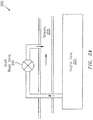
- FIG. 2A illustrates a system 200 incorporating a self-actuated start bleed valve 202.
- the valve 202 dumps highly pressurized air from an engine core 204 to a lower pressure/temperature flow stream (denoted via reference character 206).
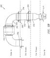
- FIG. 2B illustrates a start bleed routing system 250 in accordance with the prior art, such as in connection with the system 200.
- the system 250 includes multiple tubes 252, a first inner duct 254 and a second outer duct 256.
- the ducts are frequently associated with seals and/or cases that serve to segregate various streams (e.g., 2 nd stream and 3 rd stream) that are characterized by different temperatures and pressures. Connections (e.g., a bolted interface) associated with such seals/cases is shown via reference character 258.
- At least some of the tubes 252 attach to a valve housing 260 via a clamp 262 that frequently takes the form of a V-shape and is referred to as a ⁇ V-band'.
- core air (denoted by arrow/reference character 274 in FIG. 2B ) of the engine is routed to a different flow and pressure environment within the engine, such as the "3 rd steam" as shown in FIG 2B .
- a valve included in the housing 260 controls the flow rate of the air.
- the tubes 252 include right-angled and straight geometries. The tubes 252 attach to the exterior of the engine to route the flow (e.g., the core air 274) to the intended destination (e.g., the 3 rd stream). As shown in FIG.
- the core air 274 (1) traverses the 2 nd stream and the 3 rd stream, (2) leads to the outer air/environment, and (3) is then returned to the 3 rd stream. This is done based on the packaging that is available and the desire to provide accessibility to the valve in the housing 260; e.g., in such a configuration the valve can be treated as a line replaceable unit (LRU).
- LRU line replaceable unit
- aspects of the disclosure are directed to a system associated with an engine of an aircraft, comprising: an inlet housing configured to receive core air of the engine, and at least one valve coupled to the inlet housing and configured to bleed the core air during a starting of the engine, where the at least one valve is housed within the engine.
- the at least one valve is configured to bleed the core air into a third stream associated with the engine.
- the at least one valve is configured to bleed the core air into an ambient environment.
- the at least one valve is configured to bleed the core air at a substantial right angle relative to a major axis of the system.
- the system comprises a cover configured to seal the at least one valve from an ambient environment.
- the system comprises at least one standoff configured to secure the at least one valve to the inlet housing and secure the cover to seal the at least one valve from the ambient environment.
- the at least one valve comprises a flapper configured to rotate between an open position and a closed position.
- the flapper is configured to be in the open position during the starting of the engine.
- the flapper is configured to be in the closed position subsequent to the starting of the engine.
- the flapper is configured to remain in the closed position until the engine speed drops below a prescribed value as the engine shuts down.
- the system comprises a pivot rod coupled to the flapper that is configured to support a rotation of the flapper.
- the system comprises a spring coupled to the flapper that is configured to bias the flapper to the open position during the starting of the engine.
- the spring is a torsion spring.
- the spring is configured to bias the flapper to the closed position as a function of a spring constant of the spring in relationship to a differential pressure.
- the system comprises a first sealing interface between the core air and a second stream associated with the engine.
- the system comprises a second sealing interface between the second stream and a third stream associated with the engine.
- at least one of the first sealing interface or the second sealing interface comprises a slider seal.
- the at least one valve is located within at least one of a second stream or a third stream associated with the engine.
- connections are set forth between elements in the following description and in the drawings (the contents of which are included in this disclosure by way of reference). It is noted that these connections are general and, unless specified otherwise, may be direct or indirect and that this specification is not intended to be limiting in this respect.
- a coupling between two or more entities may refer to a direct connection or an indirect connection.
- An indirect connection may incorporate one or more intervening entities.
- FIG. 1 is a side cutaway illustration of a geared turbine engine 10.
- This turbine engine 10 extends along an axial centerline 12 between an upstream airflow inlet 14 and a downstream airflow exhaust 16.
- the turbine engine 10 includes a fan section 18, a compressor section 19, a combustor section 20 and a turbine section 21.
- the compressor section 19 includes a low pressure compressor (LPC) section 19A and a high pressure compressor (HPC) section 19B.
- the turbine section 21 includes a high pressure turbine (HPT) section 21A and a low pressure turbine (LPT) section 21B.
- the engine sections 18-21 are arranged sequentially along the centerline 12 within an engine housing 22.
- Each of the engine sections 18-19B, 21A and 21B includes a respective rotor 24-28.
- Each of these rotors 24-28 includes a plurality of rotor blades arranged circumferentially around and connected to one or more respective rotor disks.
- the rotor blades may be formed integral with or mechanically fastened, welded, brazed, adhered and/or otherwise attached to the respective rotor disk(s).
- the fan rotor 24 is connected to a gear train 30, for example, through a fan shaft 32.
- the gear train 30 and the LPC rotor 25 are connected to and driven by the LPT rotor 28 through a low speed shaft 33.
- the HPC rotor 26 is connected to and driven by the HPT rotor 27 through a high speed shaft 34.
- the shafts 32-34 are rotatably supported by a plurality of bearings 36; e.g., rolling element and/or thrust bearings. Each of these bearings 36 is connected to the engine housing 22 by at least one stationary structure such as, for example, an annular support strut.
- the air within the core gas path 38 may be referred to as "core air”.
- the air within the bypass gas path 40 may be referred to as "bypass air”.
- the core air is directed through the engine sections 19-21, and exits the turbine engine 10 through the airflow exhaust 16 to provide forward engine thrust.
- fuel is injected into a combustion chamber 42 and mixed with compressed core air. This fuel-core air mixture is ignited to power the turbine engine 10.
- the bypass air is directed through the bypass gas path 40 and out of the turbine engine 10 through a bypass nozzle 44 to provide additional forward engine thrust. This additional forward engine thrust may account for a majority (e.g., more than 70 percent) of total engine thrust.
- at least some of the bypass air may be directed out of the turbine engine 10 through a thrust reverser to provide reverse engine thrust.
- FIG. 1 represents one possible configuration for an engine 10. Aspects of the disclosure may be applied in connection with other environments, including additional configurations for gas turbine engines.
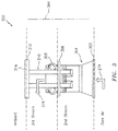
- the system 300 may include one or more of a first sealing interface 302, an inlet housing 304, a second sealing interface 306, one or more valves 308 (e.g., a dual pivot flapper valve), one or more standoffs 310, a third sealing interface 312, and a cover 314.
- a first sealing interface 302 an inlet housing 304
- a second sealing interface 306 one or more valves 308 (e.g., a dual pivot flapper valve)
- one or more standoffs 310 e.g., a dual pivot flapper valve
- the inlet housing 304 may be coupled (e.g., rigidly attached) to an inner core of the engine to provide a path for the bleed of the core air 274 into, e.g., the 3 rd stream and to obtain a grounding of the assembly. As shown via arrow 374 in FIG. 3 , the bleed air may be directed at a substantial right angle relative to a (major) axis 384 of the system assembly 300.
- the valve 308 may control/provide "open”/"closed” actuation.
- the valve 308's diminutive configuration may enable the valve 308 to be easily housed within the engine, such as for example between various engine cases.
- the standoff(s) 310 may secure the valve 308 to the inlet housing 304 and secure the closure/cover 314 to seal 312 the assembly or a portion thereof (e.g., the valve 308) from the ambient environment.
- the standoff(s) 310 may provide an exit opening for the bleed to release to.
- a significant reduction in flow restriction e.g., a flow restriction experienced in connection with the 3 rd stream flow
- Sealing between ducts/casings may be obtained via the use of one or more slider seals or any other type of seal. Any sealing that is provided may be between two or more of the core air, the 2 nd stream, the 3 rd stream, or the external/ambient environment.
- the cover 314 may provide access to the assembly 300 or one or more portions thereof. For example, the cover 314 may be removed to provide easy access to the valve 308.
- the system assembly 300 may be associated with a symmetric/non-cantilever configuration. Such a configuration may be optimum in terms of inclusion in an environment that subject to large vibration, such as for example in connection with an engine of an aircraft. Additionally, this configuration may contain internal pressure and prevent/minimize leakage to an external environment.
- a valve (e.g., valve 308) may be used to reduce pressure loads within an engine to facilitate starting the engine.
- core pressure may be vented to a lower pressure destination.
- FIG. 3 shows core pressure 274 being vented to a 3 rd stream pressure; however, any lower pressure environment/destination (including the external/ambient environment) may be used.
- the valve 308 may be configured to be open to bleed off high pressure during engine start. As the engine starts and begins to spool-up, the excessive bleed flow may trip/trigger the valve 308 to a closed/sealed position, thereby allowing for normal operation of the engine.
- the structural elements of the assembly 300 might not be located in the external/ambient environment, such that the structural elements of the assembly 300 are located/housed within the engine (e.g., within one or both of the 2 nd stream and the 3 rd stream).
- FIG. 2B wherein the housing 260 and portions of the tubes 252 are shown as being located in the external environment (labeled 'outer air' in FIG. 2B ).
- the configuration of FIG. 3 may lend itself to enhanced performance with respect to the streams (e.g., the 3 rd stream) relative to the configuration of FIG. 2B .
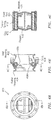
- FIG. 4A a system assembly 400 implementing a valve in accordance with aspects of the disclosure is shown.
- FIG. 4B illustrates a cross-section of the system 400 taken along the line A-A in FIG. 4A .
- FIG. 4C illustrates a cross-section of the system 400 taken along the line B-B in FIG. 4B .
- the collection of FIGS. 4A-4C is referred to herein as FIG. 4 .
- the system 400 includes a first, inlet housing 402 and a second, outlet housing 404.
- One or more seals such as for example a c-seal 406, may be included.
- a flapper is shown in a closed state/position as denoted by reference character 408a.
- the flapper is shown in an open state/position as denoted by reference character 408b.
- a spring such as for example a torsion spring 410, may bias the flapper 408 to an open position at engine start (e.g., as shown in connection with 408b).
- a spring force associated with the spring 410 may be configured for the condition where the valve should initiate closure.
- a velocity effect over the flapper 408 may provide a pressure (e.g., a lower than static pressure), thereby creating a closing force.
- the spring 410 may be configured to bias the flapper 408 to the closed position as a function of a spring constant of the spring 408 in relationship to the differential pressure.
- a maximum pressure differential may be created across the flapper 408. This approach maximizes the pressure differential across the flapper 408 as flow increases.
- the flow path geometry may be designed to ensure the full open pressure drop across the valve is met. Once closed, the valve may remain in this position for the remainder of the mission until the engine is shut down and the pressure is relieved.
- the system 400 may include a cap 422.
- the cap 422 may be used to provide for sealing and/or to minimize/prevent leakage into, e . g . , the 2 nd stream or the 3 rd stream of FIG. 3 .
- the pivot rod 424 may support the movement/rotation of the flapper 412. Additional hardware, such as one or more washers 426, may be included.
- the washer 426 may control the position of the flapper 408 with respect to the seat and control end of the flapper.
- the washer 426 may provide an intermediate surface for rotation in case of high friction between the flapper 408 and the outlet housing 404.
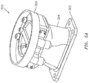
- FIGS. 5A-5B depict a system assembly 500 in accordance with aspects of this disclosure.
- the system 500 includes many of the features described above in connection with the systems 300 and 400 described above, and so, a complete re-description is omitted for the sake of brevity.
- the system 500 is shown as including a flapper in the closed state/position 508a and the open state/position 508b.
- the embodiment depicted in connection with the system 500 might not include standoffs.
- the system 500 packing is more compact relative to the packaging of the system 300.
- the profile/form factor of the system 500 is shown as being contained within the projection of the second stream, such that the third stream is free of structural elements/members.
- aspects of the disclosure provide for a structurally sound configuration with minimal parts that operate with minimal restrictions. Relative to a conventional valve assembly/system, aspects of the disclosure may enable an increase in performance with respect to one or more streams.
Landscapes
- Engineering & Computer Science (AREA)
- General Engineering & Computer Science (AREA)
- Mechanical Engineering (AREA)
- Chemical & Material Sciences (AREA)
- Combustion & Propulsion (AREA)
- Physics & Mathematics (AREA)
- Fluid Mechanics (AREA)
- Life Sciences & Earth Sciences (AREA)
- Sustainable Development (AREA)
- Aviation & Aerospace Engineering (AREA)
- Lift Valve (AREA)
- Control Of Turbines (AREA)
Abstract
Description
- In an aircraft engine environment, a bleed valve may be used during engine start to reduce a load on a compressor, allowing the engine to spin/spool-up and start faster. Typically, start valves are poppet designs or in-line style valves that require a large geometric area to meet a specified flow effective area. Conventionally, the valves tend to be bulkhead mounted or duct mounted with right angle ducting for routing along the exterior of the engine.
-
FIG. 2A illustrates asystem 200 incorporating a self-actuated start bleedvalve 202. Thevalve 202 dumps highly pressurized air from anengine core 204 to a lower pressure/temperature flow stream (denoted via reference character 206). -
FIG. 2B illustrates a startbleed routing system 250 in accordance with the prior art, such as in connection with thesystem 200. Thesystem 250 includesmultiple tubes 252, a firstinner duct 254 and a secondouter duct 256. The ducts are frequently associated with seals and/or cases that serve to segregate various streams (e.g., 2nd stream and 3rd stream) that are characterized by different temperatures and pressures. Connections (e.g., a bolted interface) associated with such seals/cases is shown viareference character 258. At least some of thetubes 252 attach to avalve housing 260 via aclamp 262 that frequently takes the form of a V-shape and is referred to as a `V-band'. - In practice, core air (denoted by arrow/
reference character 274 inFIG. 2B ) of the engine is routed to a different flow and pressure environment within the engine, such as the "3rd steam" as shown inFIG 2B . A valve included in thehousing 260 controls the flow rate of the air. As shown inFIG. 2B , thetubes 252 include right-angled and straight geometries. Thetubes 252 attach to the exterior of the engine to route the flow (e.g., the core air 274) to the intended destination (e.g., the 3rd stream). As shown inFIG. 2B , the core air 274: (1) traverses the 2nd stream and the 3rd stream, (2) leads to the outer air/environment, and (3) is then returned to the 3rd stream. This is done based on the packaging that is available and the desire to provide accessibility to the valve in thehousing 260; e.g., in such a configuration the valve can be treated as a line replaceable unit (LRU). - The following presents a simplified summary in order to provide a basic understanding of some aspects of the disclosure. The summary is not an extensive overview of the disclosure. It is neither intended to identify key or critical elements of the disclosure nor to delineate the scope of the disclosure. The following summary merely presents some concepts of the disclosure in a simplified form as a prelude to the description below.
- Aspects of the disclosure are directed to a system associated with an engine of an aircraft, comprising: an inlet housing configured to receive core air of the engine, and at least one valve coupled to the inlet housing and configured to bleed the core air during a starting of the engine, where the at least one valve is housed within the engine. In some embodiments, the at least one valve is configured to bleed the core air into a third stream associated with the engine. In some embodiments, the at least one valve is configured to bleed the core air into an ambient environment. In some embodiments, the at least one valve is configured to bleed the core air at a substantial right angle relative to a major axis of the system. In some embodiments, the system comprises a cover configured to seal the at least one valve from an ambient environment. In some embodiments, the system comprises at least one standoff configured to secure the at least one valve to the inlet housing and secure the cover to seal the at least one valve from the ambient environment. In some embodiments, the at least one valve comprises a flapper configured to rotate between an open position and a closed position. In some embodiments, the flapper is configured to be in the open position during the starting of the engine. In some embodiments, the flapper is configured to be in the closed position subsequent to the starting of the engine. In some embodiments, once the flapper is in the closed position the flapper is configured to remain in the closed position until the engine speed drops below a prescribed value as the engine shuts down. In some embodiments, the system comprises a pivot rod coupled to the flapper that is configured to support a rotation of the flapper. In some embodiments, the system comprises a spring coupled to the flapper that is configured to bias the flapper to the open position during the starting of the engine. In some embodiments, the spring is a torsion spring. In some embodiments, the spring is configured to bias the flapper to the closed position as a function of a spring constant of the spring in relationship to a differential pressure. In some embodiments, the system comprises a first sealing interface between the core air and a second stream associated with the engine. In some embodiments, the system comprises a second sealing interface between the second stream and a third stream associated with the engine. In some embodiments, at least one of the first sealing interface or the second sealing interface comprises a slider seal. In some embodiments, the at least one valve is located within at least one of a second stream or a third stream associated with the engine.
- The present disclosure is illustrated by way of example and not limited in the accompanying figures in which like reference numerals indicate similar elements.
-
FIG. 1 is a side cutaway illustration of a geared turbine engine. -
FIG. 2A illustrates a system for bleeding engine air to a stream in accordance with the prior art. -
FIG. 2B illustrates a system for bleeding engine air that incorporates tubes and a valve in accordance with the prior art. -
FIG. 3 illustrates a system assembly for implementing a valve in accordance with aspects of the disclosure. -
FIGS. 4A-4C illustrate various views of a system for implementing a valve in accordance with aspects of the disclosure. -
FIGS. 5A-5B illustrate a system assembly for implementing a valve in accordance with aspects of the disclosure. - It is noted that various connections are set forth between elements in the following description and in the drawings (the contents of which are included in this disclosure by way of reference). It is noted that these connections are general and, unless specified otherwise, may be direct or indirect and that this specification is not intended to be limiting in this respect. A coupling between two or more entities may refer to a direct connection or an indirect connection. An indirect connection may incorporate one or more intervening entities.
- Aspects of the disclosure may be applied in connection with a gas turbine engine.
FIG. 1 is a side cutaway illustration of a gearedturbine engine 10. Thisturbine engine 10 extends along anaxial centerline 12 between anupstream airflow inlet 14 and adownstream airflow exhaust 16. Theturbine engine 10 includes afan section 18, acompressor section 19, acombustor section 20 and aturbine section 21. Thecompressor section 19 includes a low pressure compressor (LPC)section 19A and a high pressure compressor (HPC)section 19B. Theturbine section 21 includes a high pressure turbine (HPT)section 21A and a low pressure turbine (LPT)section 21B. - The engine sections 18-21 are arranged sequentially along the
centerline 12 within anengine housing 22. Each of the engine sections 18-19B, 21A and 21B includes a respective rotor 24-28. Each of these rotors 24-28 includes a plurality of rotor blades arranged circumferentially around and connected to one or more respective rotor disks. The rotor blades, for example, may be formed integral with or mechanically fastened, welded, brazed, adhered and/or otherwise attached to the respective rotor disk(s). - The
fan rotor 24 is connected to agear train 30, for example, through afan shaft 32. Thegear train 30 and the LPC rotor 25 are connected to and driven by theLPT rotor 28 through alow speed shaft 33. TheHPC rotor 26 is connected to and driven by theHPT rotor 27 through ahigh speed shaft 34. The shafts 32-34 are rotatably supported by a plurality ofbearings 36; e.g., rolling element and/or thrust bearings. Each of thesebearings 36 is connected to theengine housing 22 by at least one stationary structure such as, for example, an annular support strut. - During operation, air enters the
turbine engine 10 through theairflow inlet 14, and is directed through thefan section 18 and into acore gas path 38 and abypass gas path 40. The air within thecore gas path 38 may be referred to as "core air". The air within thebypass gas path 40 may be referred to as "bypass air". The core air is directed through the engine sections 19-21, and exits theturbine engine 10 through theairflow exhaust 16 to provide forward engine thrust. Within thecombustor section 20, fuel is injected into acombustion chamber 42 and mixed with compressed core air. This fuel-core air mixture is ignited to power theturbine engine 10. The bypass air is directed through thebypass gas path 40 and out of theturbine engine 10 through abypass nozzle 44 to provide additional forward engine thrust. This additional forward engine thrust may account for a majority (e.g., more than 70 percent) of total engine thrust. Alternatively, at least some of the bypass air may be directed out of theturbine engine 10 through a thrust reverser to provide reverse engine thrust. -
FIG. 1 represents one possible configuration for anengine 10. Aspects of the disclosure may be applied in connection with other environments, including additional configurations for gas turbine engines. - Referring now to
FIG. 3 , asystem assembly 300 implementing a valve in accordance with aspects of the disclosure is shown. Thesystem 300 may include one or more of afirst sealing interface 302, aninlet housing 304, asecond sealing interface 306, one or more valves 308 (e.g., a dual pivot flapper valve), one ormore standoffs 310, athird sealing interface 312, and acover 314. - The
inlet housing 304 may be coupled (e.g., rigidly attached) to an inner core of the engine to provide a path for the bleed of thecore air 274 into, e.g., the 3rd stream and to obtain a grounding of the assembly. As shown viaarrow 374 inFIG. 3 , the bleed air may be directed at a substantial right angle relative to a (major)axis 384 of thesystem assembly 300. - The
valve 308 may control/provide "open"/"closed" actuation. Thevalve 308's diminutive configuration may enable thevalve 308 to be easily housed within the engine, such as for example between various engine cases. - The standoff(s) 310 may secure the
valve 308 to theinlet housing 304 and secure the closure/cover 314 to seal 312 the assembly or a portion thereof (e.g., the valve 308) from the ambient environment. The standoff(s) 310 may provide an exit opening for the bleed to release to. In addition, by utilizing the standoff(s) 310 a significant reduction in flow restriction (e.g., a flow restriction experienced in connection with the 3rd stream flow) may be obtained. - Sealing between ducts/casings (e.g., sealing associated with one or more of the
interfaces - The
cover 314 may provide access to theassembly 300 or one or more portions thereof. For example, thecover 314 may be removed to provide easy access to thevalve 308. - The
system assembly 300 may be associated with a symmetric/non-cantilever configuration. Such a configuration may be optimum in terms of inclusion in an environment that subject to large vibration, such as for example in connection with an engine of an aircraft. Additionally, this configuration may contain internal pressure and prevent/minimize leakage to an external environment. - In view of the
system assembly 300 ofFIG. 3 , a valve (e.g., valve 308) may be used to reduce pressure loads within an engine to facilitate starting the engine. As part of the engine start, core pressure may be vented to a lower pressure destination.FIG. 3 showscore pressure 274 being vented to a 3rd stream pressure; however, any lower pressure environment/destination (including the external/ambient environment) may be used. Thevalve 308 may be configured to be open to bleed off high pressure during engine start. As the engine starts and begins to spool-up, the excessive bleed flow may trip/trigger thevalve 308 to a closed/sealed position, thereby allowing for normal operation of the engine. - As shown in
FIG. 3 , the structural elements of theassembly 300 might not be located in the external/ambient environment, such that the structural elements of theassembly 300 are located/housed within the engine (e.g., within one or both of the 2nd stream and the 3rd stream). This may be contrasted withFIG. 2B , wherein thehousing 260 and portions of thetubes 252 are shown as being located in the external environment (labeled 'outer air' inFIG. 2B ). The configuration ofFIG. 3 may lend itself to enhanced performance with respect to the streams (e.g., the 3rd stream) relative to the configuration ofFIG. 2B . - Referring to
FIG. 4A , asystem assembly 400 implementing a valve in accordance with aspects of the disclosure is shown.FIG. 4B illustrates a cross-section of thesystem 400 taken along the line A-A inFIG. 4A . Similarly,FIG. 4C illustrates a cross-section of thesystem 400 taken along the line B-B inFIG. 4B . The collection ofFIGS. 4A-4C is referred to herein asFIG. 4 . - The
system 400 includes a first,inlet housing 402 and a second,outlet housing 404. One or more seals, such as for example a c-seal 406, may be included. InFIG. 4B , a flapper is shown in a closed state/position as denoted byreference character 408a. The flapper is shown in an open state/position as denoted byreference character 408b. - A spring, such as for example a
torsion spring 410, may bias theflapper 408 to an open position at engine start (e.g., as shown in connection with 408b). A spring force associated with thespring 410 may be configured for the condition where the valve should initiate closure. A velocity effect over theflapper 408 may provide a pressure (e.g., a lower than static pressure), thereby creating a closing force. As theflapper 408 starts to close this pressure differential increases faster than the spring force increase and the valve may snap shut (e.g., as shown in connection with 408a). In this manner, thespring 410 may be configured to bias theflapper 408 to the closed position as a function of a spring constant of thespring 408 in relationship to the differential pressure. - To make the valve snap shut within a narrow specified band a maximum pressure differential may be created across the
flapper 408. This approach maximizes the pressure differential across theflapper 408 as flow increases. The flow path geometry may be designed to ensure the full open pressure drop across the valve is met. Once closed, the valve may remain in this position for the remainder of the mission until the engine is shut down and the pressure is relieved. - As shown in
FIG. 4 , thesystem 400 may include acap 422. Thecap 422 may be used to provide for sealing and/or to minimize/prevent leakage into, e.g., the 2nd stream or the 3rd stream ofFIG. 3 . Thepivot rod 424 may support the movement/rotation of the flapper 412. Additional hardware, such as one ormore washers 426, may be included. Thewasher 426 may control the position of theflapper 408 with respect to the seat and control end of the flapper. Thewasher 426 may provide an intermediate surface for rotation in case of high friction between theflapper 408 and theoutlet housing 404. -
FIGS. 5A-5B depict asystem assembly 500 in accordance with aspects of this disclosure. Thesystem 500 includes many of the features described above in connection with thesystems system 500 is shown as including a flapper in the closed state/position 508a and the open state/position 508b. The embodiment depicted in connection with thesystem 500 might not include standoffs. Also, in comparingFIGS. 3 and5B , thesystem 500 packing is more compact relative to the packaging of thesystem 300. For example, the profile/form factor of thesystem 500 is shown as being contained within the projection of the second stream, such that the third stream is free of structural elements/members. - Technical effects and benefits of this disclosure include a provisioning of a streamlined configuration that may be used to eliminate external ducting, resulting in a significant weight reduction. In some embodiments, standoffs secure a valve to an inlet duct, support an external enclosure, and provide a reduction in terms of restriction experienced by one or more stream flows. Aspects of the disclosure provide for a structurally sound configuration with minimal parts that operate with minimal restrictions. Relative to a conventional valve assembly/system, aspects of the disclosure may enable an increase in performance with respect to one or more streams.
- Aspects of the disclosure have been described in terms of illustrative embodiments thereof. Numerous other embodiments, modifications, and variations within the scope of the appended claims will occur to persons of ordinary skill in the art from a review of this disclosure. For example, one of ordinary skill in the art will appreciate that aspects of a first embodiment may be combined with aspects of one or more additional embodiments.
Claims (15)
- A system associated with an engine of an aircraft, comprising:an inlet housing (304) configured to receive core air (274) of the engine (10); andat least one valve (308) coupled to the inlet housing (304) and configured to bleed the core air (274) during a starting of the engine (10),wherein the at least one valve (308) is housed within the engine (10).
- The system of claim 1, wherein the at least one valve (308) is configured to bleed the core air (274) into a third stream associated with the engine (10).
- The system of claim 1 or 2, wherein the at least one valve (308) is configured to bleed the core air (274) into an ambient environment.
- The system of claim 1, 2 or 3 wherein the at least one valve (308) is configured to bleed the core air (274) at a substantial right angle relative to a major axis (384) of the system.
- The system of any preceding claim, further comprising:a cover (314) configured to seal the at least one valve (308) from an ambient environment.
- The system of claim 5, further comprising:at least one standoff (310) configured to secure the at least one valve (308) to the inlet housing (402) and secure the cover (314) to seal the at least one valve (308) from the ambient environment.
- The system of any preceding claim, wherein the at least one valve (308) comprises a flapper (408) configured to rotate between an open position (408a) and a closed position (408b).
- The system of claim 7, wherein the flapper (408) is configured to be in the open position (408a) during the starting of the engine (10), and/or the flapper (408) is configured to be in the closed position (408b) subsequent to the starting of the engine (10).
- The system of claim 8, wherein once the flapper (408) is in the closed position (408b) the flapper (408) is configured to remain in the closed position (408b) until the engine speed drops below a prescribed value as the engine (10) shuts down.
- The system of claim 7, 8 or 9 further comprising:a pivot rod (424) coupled to the flapper (408) that is configured to support a rotation of the flapper (408).
- The system of any of claims 7 to 10, further comprising:a spring (410), for example a torsion spring, coupled to the flapper (408) that is configured to bias the flapper (408) to the open position (408a) during the starting of the engine (10).
- The system of claim 11, wherein the spring (410) is configured to bias the flapper (408) to the closed position (408b) as a function of a spring (410) constant of the spring in relationship to a differential pressure.
- The system of any preceding claim, further comprising:a first sealing interface (302) between the core air (274) and a second stream associated with the engine (10).
- The system of claim 13, further comprising:a second sealing interface (306) between the second stream and a third stream associated with the engine (10), wherein optionally at least one of the first sealing interface (302) or the second sealing interface (306) comprises a slider seal.
- The system of any preceding claim, wherein the at least one valve (308) is located within at least one of a second stream or a third stream associated with the engine (10).
Applications Claiming Priority (1)
| Application Number | Priority Date | Filing Date | Title |
|---|---|---|---|
| US14/717,766 US20160341130A1 (en) | 2015-05-20 | 2015-05-20 | Pneumatic porting via self-actuated dual pivot flapper valve |
Publications (1)
| Publication Number | Publication Date |
|---|---|
| EP3095985A1 true EP3095985A1 (en) | 2016-11-23 |
Family
ID=55589703
Family Applications (1)
| Application Number | Title | Priority Date | Filing Date |
|---|---|---|---|
| EP16161456.5A Withdrawn EP3095985A1 (en) | 2015-05-20 | 2016-03-21 | Pneumatic porting via self-actuated dual pivot flapper valve |
Country Status (2)
| Country | Link |
|---|---|
| US (1) | US20160341130A1 (en) |
| EP (1) | EP3095985A1 (en) |
Cited By (1)
| Publication number | Priority date | Publication date | Assignee | Title |
|---|---|---|---|---|
| WO2019197744A1 (en) * | 2018-04-13 | 2019-10-17 | Safran Aircraft Engines | Air bleed device for an aircraft engine |
Families Citing this family (2)
| Publication number | Priority date | Publication date | Assignee | Title |
|---|---|---|---|---|
| FR3083832B1 (en) * | 2018-07-10 | 2020-06-19 | Safran Aircraft Engines | DISCHARGE VALVE FOR TAKING FLUID FLOWING FROM A TURBOMACHINE VEIN |
| US11174757B2 (en) | 2020-01-20 | 2021-11-16 | Raytheon Technologies Corporation | Externally replaceable valve assembly for a turbine engine |
Citations (8)
| Publication number | Priority date | Publication date | Assignee | Title |
|---|---|---|---|---|
| US4715779A (en) * | 1984-12-13 | 1987-12-29 | United Technologies Corporation | Bleed valve for axial flow compressor |
| US20050019156A1 (en) * | 2003-07-22 | 2005-01-27 | D'angelo Gary | Bleed valve system |
| US20050116114A1 (en) * | 2002-12-18 | 2005-06-02 | Pratt & Whitney Canada Corp. | Normally open reverse flow flapper valve |
| US20070234738A1 (en) * | 2006-03-28 | 2007-10-11 | United Technologies Corporation | Self-actuating bleed valve for gas turbine engine |
| US20100119356A1 (en) * | 2008-11-12 | 2010-05-13 | Snecma | Device for regulating the flow rate of air feeding a turbine ventilation cavity of a turbomachine turbine section |
| US8128347B2 (en) * | 2006-08-25 | 2012-03-06 | Rolls-Royce Plc | Aeroengine bleed valve |
| US20120128470A1 (en) * | 2010-11-18 | 2012-05-24 | Robert Goodman | Self-actuating bleed valve for a gas turbine engine |
| US8250852B2 (en) * | 2006-01-19 | 2012-08-28 | Airbus Operations Sas | Dual flow turbine engine equipped with a precooler |
Family Cites Families (9)
| Publication number | Priority date | Publication date | Assignee | Title |
|---|---|---|---|---|
| US4671318A (en) * | 1985-02-08 | 1987-06-09 | The Garrett Corporation | Aircraft engine bleed air flow balancing technique |
| US5477673A (en) * | 1994-08-10 | 1995-12-26 | Pratt & Whitney Canada Inc. | Handling bleed valve |
| US7493770B2 (en) * | 2004-08-09 | 2009-02-24 | General Electric Company | Methods and apparatus for regulating airflow supply systems |
| US7797945B2 (en) * | 2006-09-06 | 2010-09-21 | Honeywell International Inc. | Bleed valve outlet flow deflector |
| US8196934B2 (en) * | 2007-01-10 | 2012-06-12 | United Technologies Corporation | Slider seal assembly for gas turbine engine |
| GB0810883D0 (en) * | 2008-06-16 | 2008-07-23 | Rolls Royce Plc | A bleed valve arrangement |
| WO2011162845A1 (en) * | 2010-03-26 | 2011-12-29 | Rolls-Royce North American Technologies, Inc. | Adaptive fan system for a variable cycle turbofan engine |
| US20110265490A1 (en) * | 2010-04-30 | 2011-11-03 | Kevin Samuel Klasing | Flow mixing vent system |
| US10125724B2 (en) * | 2012-01-17 | 2018-11-13 | United Technologies Corporation | Start system for gas turbine engines |
-
2015
- 2015-05-20 US US14/717,766 patent/US20160341130A1/en not_active Abandoned
-
2016
- 2016-03-21 EP EP16161456.5A patent/EP3095985A1/en not_active Withdrawn
Patent Citations (8)
| Publication number | Priority date | Publication date | Assignee | Title |
|---|---|---|---|---|
| US4715779A (en) * | 1984-12-13 | 1987-12-29 | United Technologies Corporation | Bleed valve for axial flow compressor |
| US20050116114A1 (en) * | 2002-12-18 | 2005-06-02 | Pratt & Whitney Canada Corp. | Normally open reverse flow flapper valve |
| US20050019156A1 (en) * | 2003-07-22 | 2005-01-27 | D'angelo Gary | Bleed valve system |
| US8250852B2 (en) * | 2006-01-19 | 2012-08-28 | Airbus Operations Sas | Dual flow turbine engine equipped with a precooler |
| US20070234738A1 (en) * | 2006-03-28 | 2007-10-11 | United Technologies Corporation | Self-actuating bleed valve for gas turbine engine |
| US8128347B2 (en) * | 2006-08-25 | 2012-03-06 | Rolls-Royce Plc | Aeroengine bleed valve |
| US20100119356A1 (en) * | 2008-11-12 | 2010-05-13 | Snecma | Device for regulating the flow rate of air feeding a turbine ventilation cavity of a turbomachine turbine section |
| US20120128470A1 (en) * | 2010-11-18 | 2012-05-24 | Robert Goodman | Self-actuating bleed valve for a gas turbine engine |
Cited By (3)
| Publication number | Priority date | Publication date | Assignee | Title |
|---|---|---|---|---|
| WO2019197744A1 (en) * | 2018-04-13 | 2019-10-17 | Safran Aircraft Engines | Air bleed device for an aircraft engine |
| FR3080149A1 (en) * | 2018-04-13 | 2019-10-18 | Safran Aircraft Engines | AIR COLLECTION DEVICE FOR AN AIRCRAFT ENGINE |
| US11208951B2 (en) | 2018-04-13 | 2021-12-28 | Safran Aircraft Engines | Spring preload adjustment device for an aircraft engine air bleed flap |
Also Published As
| Publication number | Publication date |
|---|---|
| US20160341130A1 (en) | 2016-11-24 |
Similar Documents
| Publication | Publication Date | Title |
|---|---|---|
| US8393857B2 (en) | Variable vane actuation system | |
| EP2384400B1 (en) | Variable pressure ratio compressor | |
| US9399951B2 (en) | Modular louver system | |
| CN107120146B (en) | Active HPC Gap Control | |
| US20130340440A1 (en) | Machined Aerodynamic Intercompressor Bleed Ports | |
| EP2800890A2 (en) | Gas turbine engine bifurcation located fan variable area nozzle | |
| US9835090B2 (en) | Fire seal for a gas turbine engine | |
| EP3483412B1 (en) | Gas turbine engine with mid-compressor bleed | |
| CN114687863A (en) | Turbine rear frame link assembly for turbofan engine | |
| EP3095985A1 (en) | Pneumatic porting via self-actuated dual pivot flapper valve | |
| US20200109796A1 (en) | Controller assembly | |
| US12553403B1 (en) | Gas turbine engine having a thrust reverser system with drag link connectors at inter-compressor frame structure | |
| WO2014120126A1 (en) | Cowl with pressure driven latch | |
| CN116265718A (en) | Divided damper seal construction for segmented internal cooling hardware | |
| EP3061946B1 (en) | Self-actuating and dual pivot flapper valve | |
| EP3203023A1 (en) | Gas turbine engine with a cooling fluid path | |
| US5822975A (en) | Bypass engine with means for limiting gas leakage | |
| EP3348799B1 (en) | Multi-flowpath fluid control valve | |
| US11840985B2 (en) | Aircraft propulsion system with variable area inlet | |
| EP3611358B1 (en) | Bleed valve actuation system | |
| US20160201566A1 (en) | Large displacement high temperature seal | |
| EP3798132A1 (en) | Nacelle cowl deflection limiter | |
| EP3907389B1 (en) | Gas turbine compressor radial door bleed valve | |
| US20240141797A1 (en) | Rotary machine seal having a wear protection assembly with an abradable covering | |
| US11255269B2 (en) | Valve arrangement for a fuel system |
Legal Events
| Date | Code | Title | Description |
|---|---|---|---|
| PUAI | Public reference made under article 153(3) epc to a published international application that has entered the european phase |
Free format text: ORIGINAL CODE: 0009012 |
|
| AK | Designated contracting states |
Kind code of ref document: A1 Designated state(s): AL AT BE BG CH CY CZ DE DK EE ES FI FR GB GR HR HU IE IS IT LI LT LU LV MC MK MT NL NO PL PT RO RS SE SI SK SM TR |
|
| AX | Request for extension of the european patent |
Extension state: BA ME |
|
| STAA | Information on the status of an ep patent application or granted ep patent |
Free format text: STATUS: REQUEST FOR EXAMINATION WAS MADE |
|
| 17P | Request for examination filed |
Effective date: 20170523 |
|
| RBV | Designated contracting states (corrected) |
Designated state(s): AL AT BE BG CH CY CZ DE DK EE ES FI FR GB GR HR HU IE IS IT LI LT LU LV MC MK MT NL NO PL PT RO RS SE SI SK SM TR |
|
| STAA | Information on the status of an ep patent application or granted ep patent |
Free format text: STATUS: EXAMINATION IS IN PROGRESS |
|
| 17Q | First examination report despatched |
Effective date: 20200616 |
|
| STAA | Information on the status of an ep patent application or granted ep patent |
Free format text: STATUS: THE APPLICATION HAS BEEN WITHDRAWN |
|
| 18W | Application withdrawn |
Effective date: 20200930 |