EP3095973A1 - Turbomachine diffuser including flow mixing lobes and method - Google Patents
Turbomachine diffuser including flow mixing lobes and method Download PDFInfo
- Publication number
- EP3095973A1 EP3095973A1 EP16169959.0A EP16169959A EP3095973A1 EP 3095973 A1 EP3095973 A1 EP 3095973A1 EP 16169959 A EP16169959 A EP 16169959A EP 3095973 A1 EP3095973 A1 EP 3095973A1
- Authority
- EP
- European Patent Office
- Prior art keywords
- diffuser
- turbomachine
- flow
- lobe
- lobe members
- Prior art date
- Legal status (The legal status is an assumption and is not a legal conclusion. Google has not performed a legal analysis and makes no representation as to the accuracy of the status listed.)
- Withdrawn
Links
- 238000000034 method Methods 0.000 title claims description 9
- 239000007789 gas Substances 0.000 claims description 30
- 239000000203 mixture Substances 0.000 description 4
- 238000011084 recovery Methods 0.000 description 3
- 239000012530 fluid Substances 0.000 description 2
- 239000000446 fuel Substances 0.000 description 2
- 230000003068 static effect Effects 0.000 description 2
- 230000004075 alteration Effects 0.000 description 1
- 238000002485 combustion reaction Methods 0.000 description 1
- 238000001816 cooling Methods 0.000 description 1
- 239000003085 diluting agent Substances 0.000 description 1
- 238000005259 measurement Methods 0.000 description 1
- 238000000926 separation method Methods 0.000 description 1
- 238000006467 substitution reaction Methods 0.000 description 1
- 230000007704 transition Effects 0.000 description 1
- 238000011144 upstream manufacturing Methods 0.000 description 1
Images



Classifications
-
- F—MECHANICAL ENGINEERING; LIGHTING; HEATING; WEAPONS; BLASTING
- F01—MACHINES OR ENGINES IN GENERAL; ENGINE PLANTS IN GENERAL; STEAM ENGINES
- F01D—NON-POSITIVE DISPLACEMENT MACHINES OR ENGINES, e.g. STEAM TURBINES
- F01D9/00—Stators
- F01D9/02—Nozzles; Nozzle boxes; Stator blades; Guide conduits, e.g. individual nozzles
- F01D9/04—Nozzles; Nozzle boxes; Stator blades; Guide conduits, e.g. individual nozzles forming ring or sector
- F01D9/041—Nozzles; Nozzle boxes; Stator blades; Guide conduits, e.g. individual nozzles forming ring or sector using blades
-
- F—MECHANICAL ENGINEERING; LIGHTING; HEATING; WEAPONS; BLASTING
- F02—COMBUSTION ENGINES; HOT-GAS OR COMBUSTION-PRODUCT ENGINE PLANTS
- F02C—GAS-TURBINE PLANTS; AIR INTAKES FOR JET-PROPULSION PLANTS; CONTROLLING FUEL SUPPLY IN AIR-BREATHING JET-PROPULSION PLANTS
- F02C3/00—Gas-turbine plants characterised by the use of combustion products as the working fluid
- F02C3/04—Gas-turbine plants characterised by the use of combustion products as the working fluid having a turbine driving a compressor
-
- F—MECHANICAL ENGINEERING; LIGHTING; HEATING; WEAPONS; BLASTING
- F01—MACHINES OR ENGINES IN GENERAL; ENGINE PLANTS IN GENERAL; STEAM ENGINES
- F01D—NON-POSITIVE DISPLACEMENT MACHINES OR ENGINES, e.g. STEAM TURBINES
- F01D25/00—Component parts, details, or accessories, not provided for in, or of interest apart from, other groups
- F01D25/30—Exhaust heads, chambers, or the like
-
- F—MECHANICAL ENGINEERING; LIGHTING; HEATING; WEAPONS; BLASTING
- F01—MACHINES OR ENGINES IN GENERAL; ENGINE PLANTS IN GENERAL; STEAM ENGINES
- F01D—NON-POSITIVE DISPLACEMENT MACHINES OR ENGINES, e.g. STEAM TURBINES
- F01D5/00—Blades; Blade-carrying members; Heating, heat-insulating, cooling or antivibration means on the blades or the members
- F01D5/02—Blade-carrying members, e.g. rotors
- F01D5/021—Blade-carrying members, e.g. rotors for flow machines or engines with only one axial stage
-
- F—MECHANICAL ENGINEERING; LIGHTING; HEATING; WEAPONS; BLASTING
- F01—MACHINES OR ENGINES IN GENERAL; ENGINE PLANTS IN GENERAL; STEAM ENGINES
- F01D—NON-POSITIVE DISPLACEMENT MACHINES OR ENGINES, e.g. STEAM TURBINES
- F01D5/00—Blades; Blade-carrying members; Heating, heat-insulating, cooling or antivibration means on the blades or the members
- F01D5/12—Blades
- F01D5/14—Form or construction
- F01D5/141—Shape, i.e. outer, aerodynamic form
-
- F—MECHANICAL ENGINEERING; LIGHTING; HEATING; WEAPONS; BLASTING
- F04—POSITIVE - DISPLACEMENT MACHINES FOR LIQUIDS; PUMPS FOR LIQUIDS OR ELASTIC FLUIDS
- F04D—NON-POSITIVE-DISPLACEMENT PUMPS
- F04D19/00—Axial-flow pumps
- F04D19/002—Axial flow fans
-
- F—MECHANICAL ENGINEERING; LIGHTING; HEATING; WEAPONS; BLASTING
- F01—MACHINES OR ENGINES IN GENERAL; ENGINE PLANTS IN GENERAL; STEAM ENGINES
- F01D—NON-POSITIVE DISPLACEMENT MACHINES OR ENGINES, e.g. STEAM TURBINES
- F01D9/00—Stators
- F01D9/02—Nozzles; Nozzle boxes; Stator blades; Guide conduits, e.g. individual nozzles
-
- F—MECHANICAL ENGINEERING; LIGHTING; HEATING; WEAPONS; BLASTING
- F05—INDEXING SCHEMES RELATING TO ENGINES OR PUMPS IN VARIOUS SUBCLASSES OF CLASSES F01-F04
- F05D—INDEXING SCHEME FOR ASPECTS RELATING TO NON-POSITIVE-DISPLACEMENT MACHINES OR ENGINES, GAS-TURBINES OR JET-PROPULSION PLANTS
- F05D2220/00—Application
- F05D2220/30—Application in turbines
- F05D2220/32—Application in turbines in gas turbines
-
- F—MECHANICAL ENGINEERING; LIGHTING; HEATING; WEAPONS; BLASTING
- F05—INDEXING SCHEMES RELATING TO ENGINES OR PUMPS IN VARIOUS SUBCLASSES OF CLASSES F01-F04
- F05D—INDEXING SCHEME FOR ASPECTS RELATING TO NON-POSITIVE-DISPLACEMENT MACHINES OR ENGINES, GAS-TURBINES OR JET-PROPULSION PLANTS
- F05D2240/00—Components
- F05D2240/10—Stators
- F05D2240/12—Fluid guiding means, e.g. vanes
- F05D2240/127—Vortex generators, turbulators, or the like, for mixing
-
- F—MECHANICAL ENGINEERING; LIGHTING; HEATING; WEAPONS; BLASTING
- F05—INDEXING SCHEMES RELATING TO ENGINES OR PUMPS IN VARIOUS SUBCLASSES OF CLASSES F01-F04
- F05D—INDEXING SCHEME FOR ASPECTS RELATING TO NON-POSITIVE-DISPLACEMENT MACHINES OR ENGINES, GAS-TURBINES OR JET-PROPULSION PLANTS
- F05D2240/00—Components
- F05D2240/35—Combustors or associated equipment
-
- F—MECHANICAL ENGINEERING; LIGHTING; HEATING; WEAPONS; BLASTING
- F05—INDEXING SCHEMES RELATING TO ENGINES OR PUMPS IN VARIOUS SUBCLASSES OF CLASSES F01-F04
- F05D—INDEXING SCHEME FOR ASPECTS RELATING TO NON-POSITIVE-DISPLACEMENT MACHINES OR ENGINES, GAS-TURBINES OR JET-PROPULSION PLANTS
- F05D2270/00—Control
- F05D2270/01—Purpose of the control system
- F05D2270/17—Purpose of the control system to control boundary layer
Definitions
- the subject matter disclosed herein relates to the art of turbomachines and, more particularly, to a turbomachine diffuser including flow mixing lobes.
- Gas turbomachines typically include a compressor portion, a turbine portion, and a combustor assembly.
- the combustor assembly mixes fluid from the compressor portion with a fuel to form a combustible mixture.
- the combustible mixture is combusted forming hot gases that pass along a hot gas path of the turbine portion.
- the turbine portion includes a number of stages having airfoils mounted to rotors that convert thermal energy from the hot gases into mechanical, rotational energy. Additional fluid from the compressor is passed through the airfoils and other sections of the turbine portion for cooling purposes.
- Hot gases pass, as exhaust gases, from the turbine portion into an exhaust diffuser.
- the exhaust diffuser is geometrically configured to rapidly decrease the kinetic energy of flow and increase static pressure recovery within the exhaust diffuser.
- the exhaust diffuser typically includes one or more stationary struts for mechanical support. The exhaust gases may pass from the exhaust diffuser to a downstream component.
- a turbomachine diffuser includes a body having an inner surface defining a diffuser flow path, a plurality of stationary struts extending from the inner surface, and a plurality of flow mixing lobes arranged in an annular array on the inner surface.
- the plurality of flow mixing lobes is configured and disposed to guide a substantially high momentum flow toward the inner surface of the body.
- a turbomachine includes a compressor portion, and a turbine portion operatively connected to the compressor portion.
- the turbine portion includes an outlet.
- a combustor assembly including, at least one combustor, is fluidically connected to the compressor portion and the turbine portion.
- a diffuser is fluidically connected to the outlet of the turbine portion.
- the diffuser includes a body having an inner surface defining a diffuser flow path, a plurality of stationary struts extending from the inner surface, and a plurality of flow mixing lobes arranged in an annular array on the inner surface. The plurality of flow mixing lobes is configured and disposed to guide a substantially high momentum flow toward the inner surface of the body.
- a method of passing exhaust gases from a turbomachine into a diffuser includes passing hot gases toward an outlet of a turbine portion of the turbomachine, delivering the hot gases into an inlet of the diffuser, directing a portion of the hot gases toward a plurality of flow mixing lobes arranged circumferentially about an inner surface of the diffuser, forming the portion of the hot gases into a substantially high momentum flow, guiding the substantially high momentum flow toward the inner surface of the diffuser, and mixing the substantially high momentum flow with a boundary layer flow passing along the inner surface.
- a turbomachine system in accordance with an exemplary embodiment, is indicated generally at 2, in FIG. 1 .
- Turbomachine system 2 includes a turbomachine 4 having a compressor portion 6 operatively connected to a turbine portion 8 through a common compressor/turbine shaft 10.
- a combustor assembly 12 is fluidically connected between compressor portion 6 and turbine portion 8.
- Combustor assembly 12 includes at least one combustor 14 that directs products of combustion along a hot gas path (also not separately labeled) of turbine portion 8.
- An intake system 20 is fluidically connected to an inlet (not separately labeled) of compressor portion 6.
- a load 22 is mechanically linked to turbomachine 4.
- Intake system 20 may condition the air by, for example, lowering humidity, altering temperature, and the like.
- the air is compressed through multiple stages of compressor portion 6 and passed to turbine portion 8 and combustor assembly 12.
- the air is mixed with fuel, diluents, and the like, in combustor 14 to form a combustible mixture.
- the combustible mixture is passed from combustor 14 into turbine portion 8 via a transition piece (not shown) as hot gases.
- the hot gases flow along the hot gas path of turbine portion 8 and pass as exhaust into an exhaust diffuser 30.
- Exhaust diffuser 30 is geometrically configured to rapidly decrease kinetic energy of exhaust gases as well as increase static pressure recovery prior to delivery to a downstream device (not shown).
- the downstream device may direct the exhaust gases to ambient, or extract additional energy that may be used for other purposes.
- exhaust diffuser 30 includes a body 40 having an outer surface 41 and an inner surface 42 that defines a diffuser flow path 44.
- Exhaust diffuser 30 includes an inlet 46 fluidically coupled to an outlet (not separately labeled) of turbine portion 8 and an outlet 47.
- Exhaust diffuser 30 is also shown to include a plurality of stationary struts, one of which is indicated at 50, extending radially inwardly to diffuser flow path 44 from inner surface 42. Stationary struts 50 condition exhaust gases flowing along diffuser flow path 44 toward outlet 47.
- exhaust diffuser 30 includes a plurality of flow mixing lobes, one of which is indicated at 54, mounted to inner surface 42.
- flow mixing lobes 54 may be arranged downstream of inlet 46 a distance between about 0.05 times a last stage blade height and about 10 times the last stage blade height.
- flow mixing lobes 54 may be arranged downstream of inlet 46 and upstream of struts 50.
- flow mixing lobes 54 may be arranged about 2-inches (5.08-cm) downstream of inlet 46.
- flow mixing lobes 54 may be arranged about 1.50-inches (3.81-cm) downstream of inlet 46.
- position of flow mixing lobes 54 may vary.
- flow mixing lobes may be arranged downstream of struts 50.
- flow mixing lobes 54 include a first lobe member 60 and a second lobe member 61. Each lobe member 60 and 61 extends substantially perpendicularly outwardly from inner surface 42.
- First lobe member 60 includes a first base section 64 and second lobe member 61 includes a second base section 65.
- First base section 64 projects outwardly of first lobe member 60 in a first direction and second base section 65 projects outwardly of second lobe member 61 in a second direction that is opposite the first direction.
- First and second base sections 64 and 65 provide an attachment interface between respective ones of first and second lobe members 60 and 61 and inner surface 42.
- flow mixing lobes 54 include an airfoil portion 70 extending between first and second lobe member 60 and 61. Airfoil portion 70 is spaced from first and second base sections 64 and 65 such that, when attached to inner surface 42, a channel 74 is formed. Channel 74 receives a portion of exhaust gases passing from turbine portion 8. In accordance with an aspect of an exemplary embodiment, channel 74 guides a portion of a high momentum flow passing from turbine portion 6 radially outwardly toward inner surface 42. More specifically, airfoil portion 70 directs the portion of the substantially high momentum flow radially outwardly toward inner surface 42 thereby generating flow vortices.
- the flow vortices reduce boundary layer growth at inner surface 42 resulting in a reduction in flow separation.
- the exemplary embodiments thus improve pressure recovery in exhaust diffuser 30 that leads to an enhancement in overall system efficiency.
- substantially high momentum flow describes a flow having a velocity of about 1000 ft/sec (about 305 m/s) or greater.
- FIG. 5 depicts a flow mixing lobe 90 in accordance with another aspect of an exemplary embodiment.
- Flow mixing lobe 90 includes first and second lobe portions 92 and 93 joined through an airfoil portion 94.
- Each lobe portion 92 and 93 includes a corresponding terminal end portion 96 and 97 that directly interfaces with inner surface 42 of exhaust diffuser 30.
- FIG. 6 depicts a flow mixing lobe 100 including first and second lobe members 102 and 103 joined by an airfoil portion 105.
- first and second lobe members 102 and 103 include corresponding terminal end portions 107 and 108 that are angled inwardly toward each other.
- FIG. 7 depicts a flow mixing lobe 110 including first and second lobe members 112 and 113 joined by an airfoil portion 115.
- first and second lobe members 112 and 113 including corresponding terminal end portions 117 and 118 that are angled outwardly away from one another.
- FIG. 8 depicts a flow mixing lobe 120 having first and second lobe members 122 and 123 joined by an airfoil portion 124.
- airfoil portion 124 includes first and second airfoil members 128 and 129 that extend at an angle from corresponding ones of first and second lobe members 122 and 123 and are joined at an angled portion 130.
- FIG. 9 depicts a flow mixing lobe 140 including an airfoil portion 142 having a generally rectangular cross-section (not separately labeled).
- FIG. 10 depicts a flow mixing lobe 150 including an airfoil portion 152 having a curvilinear cross-section (also not separately labeled).
Landscapes
- Engineering & Computer Science (AREA)
- Mechanical Engineering (AREA)
- General Engineering & Computer Science (AREA)
- Chemical & Material Sciences (AREA)
- Combustion & Propulsion (AREA)
- Physics & Mathematics (AREA)
- Fluid Mechanics (AREA)
- Structures Of Non-Positive Displacement Pumps (AREA)
- Turbine Rotor Nozzle Sealing (AREA)
Abstract
Description
- The subject matter disclosed herein relates to the art of turbomachines and, more particularly, to a turbomachine diffuser including flow mixing lobes.
- Gas turbomachines typically include a compressor portion, a turbine portion, and a combustor assembly. The combustor assembly mixes fluid from the compressor portion with a fuel to form a combustible mixture. The combustible mixture is combusted forming hot gases that pass along a hot gas path of the turbine portion. The turbine portion includes a number of stages having airfoils mounted to rotors that convert thermal energy from the hot gases into mechanical, rotational energy. Additional fluid from the compressor is passed through the airfoils and other sections of the turbine portion for cooling purposes. Hot gases pass, as exhaust gases, from the turbine portion into an exhaust diffuser. The exhaust diffuser is geometrically configured to rapidly decrease the kinetic energy of flow and increase static pressure recovery within the exhaust diffuser. The exhaust diffuser typically includes one or more stationary struts for mechanical support. The exhaust gases may pass from the exhaust diffuser to a downstream component.
- According to one aspect of an exemplary embodiment, a turbomachine diffuser includes a body having an inner surface defining a diffuser flow path, a plurality of stationary struts extending from the inner surface, and a plurality of flow mixing lobes arranged in an annular array on the inner surface. The plurality of flow mixing lobes is configured and disposed to guide a substantially high momentum flow toward the inner surface of the body.
- According to another aspect of an exemplary embodiment, a turbomachine includes a compressor portion, and a turbine portion operatively connected to the compressor portion. The turbine portion includes an outlet. A combustor assembly including, at least one combustor, is fluidically connected to the compressor portion and the turbine portion. A diffuser is fluidically connected to the outlet of the turbine portion. The diffuser includes a body having an inner surface defining a diffuser flow path, a plurality of stationary struts extending from the inner surface, and a plurality of flow mixing lobes arranged in an annular array on the inner surface. The plurality of flow mixing lobes is configured and disposed to guide a substantially high momentum flow toward the inner surface of the body.
- According to yet another aspect of an exemplary embodiment, a method of passing exhaust gases from a turbomachine into a diffuser includes passing hot gases toward an outlet of a turbine portion of the turbomachine, delivering the hot gases into an inlet of the diffuser, directing a portion of the hot gases toward a plurality of flow mixing lobes arranged circumferentially about an inner surface of the diffuser, forming the portion of the hot gases into a substantially high momentum flow, guiding the substantially high momentum flow toward the inner surface of the diffuser, and mixing the substantially high momentum flow with a boundary layer flow passing along the inner surface.
- These and other advantages and features will become more apparent from the following description taken in conjunction with the drawings.
- The subject matter, which is regarded as the present disclosure, is particularly pointed out and distinctly claimed in the claims at the conclusion of the specification. The foregoing and other features, and advantages of the present disclosure are apparent from the following detailed description taken in conjunction with the accompanying drawings in which:
-
FIG. 1 depicts a schematic view of a turbomachine system including an exhaust diffuser having flow mixing lobes, in accordance with an exemplary embodiment; -
FIG. 2 depicts a partial cross-sectional side view of the diffuser ofFIG. 1 ; -
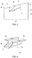
FIG. 3 depicts a flow mixing lobe mounted to an inner surface of the diffuser ofFIG. 1 ; -
FIG. 4 depicts a perspective view of the flow mixing lobe ofFIG. 3 ; -
FIG. 5 depicts a flow mixing lobe, in accordance with another aspect of an exemplary embodiment; -
FIG. 6 depicts a flow mixing lobe, in accordance with yet another aspect of an exemplary embodiment; -
FIG. 7 depicts a flow mixing lobe, in accordance with still yet another aspect of an exemplary embodiment -
FIG. 8 depicts a flow mixing lobe, in accordance with yet still another aspect of an exemplary embodiment; -
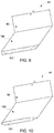
FIG. 9 depicts a cross-sectional view of a flow mixing lobe including an airfoil portion, in accordance with an aspect of an exemplary embodiment; and -
FIG. 10 depicts a cross-sectional view of a flow mixing lobe including an airfoil portion, in accordance with another aspect of an exemplary embodiment. - The detailed description explains embodiments of the present disclosure, together with advantages and features, by way of example with reference to the drawings.
- A turbomachine system, in accordance with an exemplary embodiment, is indicated generally at 2, in
FIG. 1 .Turbomachine system 2 includes aturbomachine 4 having acompressor portion 6 operatively connected to aturbine portion 8 through a common compressor/turbine shaft 10. Acombustor assembly 12 is fluidically connected betweencompressor portion 6 andturbine portion 8.Combustor assembly 12 includes at least onecombustor 14 that directs products of combustion along a hot gas path (also not separately labeled) ofturbine portion 8. Anintake system 20 is fluidically connected to an inlet (not separately labeled) ofcompressor portion 6. Aload 22 is mechanically linked toturbomachine 4. - In operation, air is passed through
intake system 20 intocompressor portion 6.Intake system 20 may condition the air by, for example, lowering humidity, altering temperature, and the like. The air is compressed through multiple stages ofcompressor portion 6 and passed toturbine portion 8 andcombustor assembly 12. The air is mixed with fuel, diluents, and the like, incombustor 14 to form a combustible mixture. The combustible mixture is passed fromcombustor 14 intoturbine portion 8 via a transition piece (not shown) as hot gases. The hot gases flow along the hot gas path ofturbine portion 8 and pass as exhaust into anexhaust diffuser 30.Exhaust diffuser 30 is geometrically configured to rapidly decrease kinetic energy of exhaust gases as well as increase static pressure recovery prior to delivery to a downstream device (not shown). The downstream device may direct the exhaust gases to ambient, or extract additional energy that may be used for other purposes. - As shown in
FIG. 2 ,exhaust diffuser 30 includes abody 40 having anouter surface 41 and aninner surface 42 that defines adiffuser flow path 44.Exhaust diffuser 30 includes aninlet 46 fluidically coupled to an outlet (not separately labeled) ofturbine portion 8 and anoutlet 47.Exhaust diffuser 30 is also shown to include a plurality of stationary struts, one of which is indicated at 50, extending radially inwardly todiffuser flow path 44 frominner surface 42.Stationary struts 50 condition exhaust gases flowing alongdiffuser flow path 44 towardoutlet 47. - In accordance with an exemplary embodiment,
exhaust diffuser 30 includes a plurality of flow mixing lobes, one of which is indicated at 54, mounted toinner surface 42. In accordance with an aspect of an exemplary embodiment,flow mixing lobes 54 may be arranged downstream of inlet 46 a distance between about 0.05 times a last stage blade height and about 10 times the last stage blade height. In an exemplary aspect shown,flow mixing lobes 54 may be arranged downstream ofinlet 46 and upstream ofstruts 50. In accordance with another aspect of an exemplary embodiment,flow mixing lobes 54 may be arranged about 2-inches (5.08-cm) downstream ofinlet 46. In accordance with yet another aspect of an exemplary embodiment,flow mixing lobes 54 may be arranged about 1.50-inches (3.81-cm) downstream ofinlet 46. Of course, it should be understood that the position offlow mixing lobes 54 may vary. Further, it should be understood that flow mixing lobes may be arranged downstream ofstruts 50. - As shown in
FIGs. 3 and 4 ,flow mixing lobes 54 include afirst lobe member 60 and asecond lobe member 61. Eachlobe member inner surface 42.First lobe member 60 includes afirst base section 64 andsecond lobe member 61 includes asecond base section 65.First base section 64 projects outwardly offirst lobe member 60 in a first direction andsecond base section 65 projects outwardly ofsecond lobe member 61 in a second direction that is opposite the first direction. First andsecond base sections second lobe members inner surface 42. - In further accordance with an exemplary embodiment,
flow mixing lobes 54 include anairfoil portion 70 extending between first andsecond lobe member Airfoil portion 70 is spaced from first andsecond base sections inner surface 42, achannel 74 is formed.Channel 74 receives a portion of exhaust gases passing fromturbine portion 8. In accordance with an aspect of an exemplary embodiment,channel 74 guides a portion of a high momentum flow passing fromturbine portion 6 radially outwardly towardinner surface 42. More specifically,airfoil portion 70 directs the portion of the substantially high momentum flow radially outwardly towardinner surface 42 thereby generating flow vortices. The flow vortices reduce boundary layer growth atinner surface 42 resulting in a reduction in flow separation. The exemplary embodiments thus improve pressure recovery inexhaust diffuser 30 that leads to an enhancement in overall system efficiency. At this point, it should be understood that the term "substantially high momentum flow" describes a flow having a velocity of about 1000 ft/sec (about 305 m/s) or greater. -
FIG. 5 depicts aflow mixing lobe 90 in accordance with another aspect of an exemplary embodiment. Flow mixinglobe 90 includes first andsecond lobe portions airfoil portion 94. Eachlobe portion terminal end portion inner surface 42 ofexhaust diffuser 30.FIG. 6 depicts aflow mixing lobe 100 including first andsecond lobe members airfoil portion 105. In the exemplary aspect shown, first andsecond lobe members terminal end portions -
FIG. 7 depicts aflow mixing lobe 110 including first andsecond lobe members airfoil portion 115. In the exemplary aspect shown, first andsecond lobe members terminal end portions FIG. 8 depicts aflow mixing lobe 120 having first andsecond lobe members airfoil portion 124. In the exemplary aspect shown,airfoil portion 124 includes first andsecond airfoil members second lobe members angled portion 130.FIG. 9 depicts aflow mixing lobe 140 including anairfoil portion 142 having a generally rectangular cross-section (not separately labeled).FIG. 10 depicts aflow mixing lobe 150 including anairfoil portion 152 having a curvilinear cross-section (also not separately labeled). - The Applicant respectfully submits that the term "about" is intended to include the degree of error associated with measurement of the particular quantity based upon the equipment available at the time of filing the application. For example, "about" can include a range of ± 8% or 5%, or 2% of a given value.
- The terminology used herein is for the purpose of describing particular embodiments only and is not intended to be limiting of the exemplary embodiment. As used herein, the singular forms "a", "an" and "the" are intended to include the plural forms as well, unless the context clearly indicates otherwise. It will be further understood that the terms "comprises" and/or "comprising," when used in this specification, specify the presence of stated features, integers, steps, operations, elements, and/or components, but do not preclude the presence or addition of one more other features, integers, steps, operations, element components, and/or groups thereof.
- While the present disclosure has been described in detail in connection with only a limited number of embodiments, it should be readily understood that the present disclosure is not limited to such disclosed embodiments. Rather, the present disclosure can be modified to incorporate any number of variations, alterations, substitutions or equivalent arrangements not heretofore described, but which are commensurate with the spirit and scope of the present disclosure. Additionally, while various embodiments of the present disclosure have been described, it is to be understood that aspects of the present disclosure may include only some of the described embodiments. Accordingly, the present disclosure is not to be seen as limited by the foregoing description, but is only limited by the scope of the appended claims.
- Various aspects and embodiments of the present invention are defined by the following numbered clauses:
- 1. A turbomachine diffuser comprising:
- a body having an inner surface defining a diffuser flow path;
- a plurality of stationary struts extending from the inner surface; and
- a plurality of flow mixing lobes arranged in an annular array on the inner surface, wherein the plurality of flow mixing lobes is configured and disposed to guide a substantially high momentum flow toward the inner surface of the body.
- 2. The turbomachine diffuser as claimed in clause 1, wherein each of the plurality of flow mixing lobes includes a first lobe member and a second lobe member, each of the first and second lobe members extending radially outwardly of the inner surface into the diffuser flow path.
- 3. The turbomachine diffuser as claimed in any preceding clause, wherein at least one of the first and second lobe members extends substantially perpendicularly from the inner surface.
- 4. The turbomachine diffuser as claimed in any preceding clause, wherein at least one of the first and second lobe members extends at an angle from the inner surface.
- 5. The turbomachine diffuser as claimed in any preceding clause, further comprising: an airfoil portion extending between the first and second lobe members.
- 6. The turbomachine diffuser as claimed in any preceding clause, wherein the airfoil portion includes one of a substantially rectangular cross-section and a curvilinear cross-section.
- 7. The turbomachine diffuser as claimed in any preceding clause, wherein the airfoil portion includes first and second airfoil members extending from corresponding ones of the first and second lobe members at a non-perpendicular angle.
- 8. The turbomachine diffuser as claimed in any preceding clause, wherein at least one of the first and second lobe members includes a base section extending circumferentially outwardly of the one of the first and second lobe members, the base section being joined to the inner surface of the body.
- 9. The turbomachine diffuser as claimed in any preceding clause, wherein the base section extends substantially perpendicularly outwardly of the one of the first and second lobe members away from the other of the first and second lobe members.
- 10. A turbomachine comprising:
- a compressor portion;
- a turbine portion operatively connected to the compressor portion, the turbine portion including an outlet;
- a combustor assembly including at least one combustor fluidically connected to the compressor portion and the turbine portion; and
- a diffuser fluidically connected to the outlet of the turbine portion, the diffuser comprising:
- a body having an inner surface defining a diffuser flow path;
- a plurality of stationary struts extending from the inner surface; and
- a plurality of flow mixing lobes arranged in an annular array on the inner surface, wherein the plurality of flow mixing lobes is configured and disposed to guide a substantially high momentum flow toward the inner surface of the body.
- 11. The turbomachine as claimed in any preceding clause, wherein each of the plurality of flow mixing lobes includes a first lobe member and a second lobe member, each of the first and second lobe members extending radially outwardly of the inner surface into the diffuser flow path.
- 12. The turbomachine as claimed in any preceding clause, wherein at least one of the first and second lobe members extends substantially perpendicularly from the inner surface.
- 13. The turbomachine as claimed in any preceding clause, wherein at least one of the first and second lobe members extends at an angle from the inner surface.
- 14. The turbomachine as claimed in any preceding clause, further comprising: an airfoil portion extending between the first and second lobe members.
- 15. The turbomachine as claimed in any preceding clause, wherein the airfoil portion includes one of a substantially rectangular cross-section and a curvilinear cross-section.
- 16. The turbomachine as claimed in any preceding clause, wherein the airfoil portion includes first and second airfoil members extending from corresponding ones of the first and second lobe members at a non-perpendicular angle.
- 17. The turbomachine as claimed in any preceding clause, wherein at least one of the first and second lobe members includes a base section extending circumferentially outwardly of the one of the first and second lobe members, the base section being joined to the inner surface of the body.
- 18. A method of passing exhaust gases from a turbomachine into a diffuser, the method comprising:
- passing hot gases toward an outlet of a turbine portion of the turbomachine;
- delivering the hot gases into an inlet of the diffuser;
- directing a portion of the hot gases toward a plurality of flow mixing lobes arranged circumferentially about an inner surface of the diffuser;
- forming the portion of the hot gases into a substantially high momentum flow;
- guiding the substantially high momentum flow toward the inner surface of the diffuser; and
- mixing the substantially high momentum flow with a boundary layer flow passing along the inner surface.
- 19. The method as claimed in any preceding clause, wherein guiding the substantially high momentum flow toward the inner surface of the diffuser includes directing a flow passing from an outlet of a turbine portion of a turbomachine across an airfoil portion of a plurality of flow mixing lobes.
- 20. The method as claimed in any preceding clause, wherein directing the flow across an airfoil portion of a plurality of flow mixing lobes includes passing the flow across an airfoil portion extending between first and second lobe members of the plurality of flow mixing lobes.
Claims (15)
- A turbomachine diffuser comprising:a body having an inner surface defining a diffuser flow path;a plurality of stationary struts extending from the inner surface; anda plurality of flow mixing lobes arranged in an annular array on the inner surface, wherein the plurality of flow mixing lobes is configured and disposed to guide a substantially high momentum flow toward the inner surface of the body.
- The turbomachine diffuser as claimed in claim 1, wherein each of the plurality of flow mixing lobes includes a first lobe member and a second lobe member, each of the first and second lobe members extending radially outwardly of the inner surface into the diffuser flow path.
- The turbomachine diffuser as claimed in claim 2, wherein at least one of the first and second lobe members extends substantially perpendicularly from the inner surface.
- The turbomachine diffuser as claimed in claim 2, wherein at least one of the first and second lobe members extends at an angle from the inner surface.
- The turbomachine diffuser as claimed in claim 2, 3 or 4, further comprising: an airfoil portion extending between the first and second lobe members.
- The turbomachine diffuser as claimed in any preceding claim, wherein at least one of the first and second lobe members includes a base section extending circumferentially outwardly of the one of the first and second lobe members, the base section being joined to the inner surface of the body.
- The turbomachine diffuser as claimed in claim 6, wherein the base section extends substantially perpendicularly outwardly of the one of the first and second lobe members away from the other of the first and second lobe members.
- A turbomachine comprising:a compressor portion;a turbine portion operatively connected to the compressor portion, the turbine portion including an outlet;a combustor assembly including at least one combustor fluidically connected to the compressor portion and the turbine portion; anda diffuser fluidically connected to the outlet of the turbine portion, the diffuser comprising:a body having an inner surface defining a diffuser flow path;a plurality of stationary struts extending from the inner surface; anda plurality of flow mixing lobes arranged in an annular array on the inner surface, wherein the plurality of flow mixing lobes is configured and disposed to guide a substantially high momentum flow toward the inner surface of the body.
- The turbomachine as claimed in claim 8, wherein each of the plurality of flow mixing lobes includes a first lobe member and a second lobe member, each of the first and second lobe members extending radially outwardly of the inner surface into the diffuser flow path.
- The turbomachine as claimed in claim 9, wherein at least one of the first and second lobe members extends substantially perpendicularly from the inner surface.
- The turbomachine as claimed in claim 9, wherein at least one of the first and second lobe members extends at an angle from the inner surface.
- The turbomachine as claimed in claim 9, 10 or 11, further comprising: an airfoil portion extending between the first and second lobe members.
- The turbomachine as claimed in any of claims 9 to 12, wherein at least one of the first and second lobe members includes a base section extending circumferentially outwardly of the one of the first and second lobe members, the base section being joined to the inner surface of the body.
- A method of passing exhaust gases from a turbomachine into a diffuser, the method comprising:passing hot gases toward an outlet of a turbine portion of the turbomachine;delivering the hot gases into an inlet of the diffuser;directing a portion of the hot gases toward a plurality of flow mixing lobes arranged circumferentially about an inner surface of the diffuser;forming the portion of the hot gases into a substantially high momentum flow;guiding the substantially high momentum flow toward the inner surface of the diffuser; andmixing the substantially high momentum flow with a boundary layer flow passing along the inner surface.
- The method as claimed in claim 14, wherein guiding the substantially high momentum flow toward the inner surface of the diffuser includes directing a flow passing from an outlet of a turbine portion of a turbomachine across an airfoil portion of a plurality of flow mixing lobes.
Applications Claiming Priority (1)
| Application Number | Priority Date | Filing Date | Title |
|---|---|---|---|
| IN2581CH2015 | 2015-05-22 |
Publications (1)
| Publication Number | Publication Date |
|---|---|
| EP3095973A1 true EP3095973A1 (en) | 2016-11-23 |
Family
ID=56008547
Family Applications (1)
| Application Number | Title | Priority Date | Filing Date |
|---|---|---|---|
| EP16169959.0A Withdrawn EP3095973A1 (en) | 2015-05-22 | 2016-05-17 | Turbomachine diffuser including flow mixing lobes and method |
Country Status (4)
| Country | Link |
|---|---|
| US (1) | US10344604B2 (en) |
| EP (1) | EP3095973A1 (en) |
| JP (1) | JP2016217355A (en) |
| CN (1) | CN106168165A (en) |
Families Citing this family (2)
| Publication number | Priority date | Publication date | Assignee | Title |
|---|---|---|---|---|
| USD786419S1 (en) * | 2016-05-16 | 2017-05-09 | Kewaunee Scientific Corporation | Baffle for fume hoods |
| US10718222B2 (en) * | 2017-03-27 | 2020-07-21 | General Electric Company | Diffuser-deswirler for a gas turbine engine |
Citations (3)
| Publication number | Priority date | Publication date | Assignee | Title |
|---|---|---|---|---|
| GB702273A (en) * | 1949-05-18 | 1954-01-13 | Lysholm Alf | Improvements in or relating to gas turbine power plants |
| US4971768A (en) * | 1987-11-23 | 1990-11-20 | United Technologies Corporation | Diffuser with convoluted vortex generator |
| US20100146980A1 (en) * | 2007-05-22 | 2010-06-17 | Volvo Aero Corporation | masking arrangement for a gas turbine engine |
Family Cites Families (24)
| Publication number | Priority date | Publication date | Assignee | Title |
|---|---|---|---|---|
| US2352790A (en) * | 1941-03-29 | 1944-07-04 | United Aircraft Corp | Air intake scoop |
| US2650752A (en) * | 1949-08-27 | 1953-09-01 | United Aircraft Corp | Boundary layer control in blowers |
| FR1104644A (en) * | 1954-02-15 | 1955-11-22 | Thomson Houston Comp Francaise | Improvements to Fluid Flow Control Systems |
| DE3521329A1 (en) * | 1985-06-14 | 1986-12-18 | Messerschmitt-Bölkow-Blohm GmbH, 8012 Ottobrunn | Vortex generator and boundary layer deflector arrangement |
| US5058837A (en) | 1989-04-07 | 1991-10-22 | Wheeler Gary O | Low drag vortex generators |
| US5088892A (en) | 1990-02-07 | 1992-02-18 | United Technologies Corporation | Bowed airfoil for the compression section of a rotary machine |
| JPH08260905A (en) | 1995-03-28 | 1996-10-08 | Mitsubishi Heavy Ind Ltd | Exhaust diffuser for axial turbine |
| US6896475B2 (en) * | 2002-11-13 | 2005-05-24 | General Electric Company | Fluidic actuation for improved diffuser performance |
| US8257036B2 (en) * | 2004-04-09 | 2012-09-04 | Norris Thomas R | Externally mounted vortex generators for flow duct passage |
| BRPI0700765A (en) * | 2007-02-15 | 2007-12-04 | Embraer Aeronautica Sa | vortex generator to improve performance of recessed air intakes |
| EP1970539A1 (en) * | 2007-03-13 | 2008-09-17 | Siemens Aktiengesellschaft | Diffuser assembly |
| EP2129908B1 (en) | 2007-03-20 | 2010-12-01 | Vestas Wind Systems A/S | Wind turbine blades with vortex generators |
| US8408491B2 (en) * | 2007-04-24 | 2013-04-02 | United Technologies Corporation | Nacelle assembly having inlet airfoil for a gas turbine engine |
| US8257025B2 (en) * | 2008-04-21 | 2012-09-04 | Siemens Energy, Inc. | Combustion turbine including a diffuser section with cooling fluid passageways and associated methods |
| US8087250B2 (en) | 2008-06-26 | 2012-01-03 | General Electric Company | Duplex tab exhaust nozzle |
| US8528601B2 (en) * | 2009-03-30 | 2013-09-10 | The Regents Of The University Of Michigan | Passive boundary layer control elements |
| JP5422470B2 (en) | 2010-04-05 | 2014-02-19 | 株式会社東芝 | Axial flow turbine |
| EP2484898B1 (en) | 2011-02-04 | 2014-04-23 | LM WP Patent Holding A/S | Vortex generator device with tapered sections for a wind turbine |
| US9429071B2 (en) | 2011-06-23 | 2016-08-30 | Continuum Dynamics, Inc. | Supersonic engine inlet diffuser with deployable vortex generators |
| US9051057B2 (en) * | 2011-12-28 | 2015-06-09 | Embraer S.A. | Aircraft air inlet diverter assemblies with improved aerodynamic characteristics |
| US20130170969A1 (en) * | 2012-01-04 | 2013-07-04 | General Electric Company | Turbine Diffuser |
| FR2993021B1 (en) | 2012-07-06 | 2014-08-22 | Snecma | TURBOMACHINE WITH VARIABLE SHIFT GENERATOR |
| US9926942B2 (en) * | 2015-10-27 | 2018-03-27 | Pratt & Whitney Canada Corp. | Diffuser pipe with vortex generators |
| FR3059735B1 (en) * | 2016-12-05 | 2020-09-25 | Safran Aircraft Engines | TURBOMACHINE PART WITH NON-AXISYMETRIC SURFACE |
-
2016
- 2016-05-16 JP JP2016097537A patent/JP2016217355A/en active Pending
- 2016-05-17 EP EP16169959.0A patent/EP3095973A1/en not_active Withdrawn
- 2016-05-20 CN CN201610336580.0A patent/CN106168165A/en active Pending
- 2016-05-20 US US15/159,850 patent/US10344604B2/en active Active
Patent Citations (3)
| Publication number | Priority date | Publication date | Assignee | Title |
|---|---|---|---|---|
| GB702273A (en) * | 1949-05-18 | 1954-01-13 | Lysholm Alf | Improvements in or relating to gas turbine power plants |
| US4971768A (en) * | 1987-11-23 | 1990-11-20 | United Technologies Corporation | Diffuser with convoluted vortex generator |
| US20100146980A1 (en) * | 2007-05-22 | 2010-06-17 | Volvo Aero Corporation | masking arrangement for a gas turbine engine |
Also Published As
| Publication number | Publication date |
|---|---|
| US20160341053A1 (en) | 2016-11-24 |
| JP2016217355A (en) | 2016-12-22 |
| CN106168165A (en) | 2016-11-30 |
| US10344604B2 (en) | 2019-07-09 |
Similar Documents
| Publication | Publication Date | Title |
|---|---|---|
| CN106948866B (en) | Turbine and turbine blade thereof | |
| US10577955B2 (en) | Airfoil assembly with a scalloped flow surface | |
| EP3093436A1 (en) | Blade/disk dovetail backcut for blade/disk stress reduction for a second stage of a turbomachine | |
| US11156099B2 (en) | Turbine engine airfoil with a modified leading edge | |
| US10815789B2 (en) | Impingement holes for a turbine engine component | |
| US20130230379A1 (en) | Rotating turbomachine component having a tip leakage flow guide | |
| EP2660431A2 (en) | Gas turbomachine including a counter-flow cooling system and method | |
| EP2679772A1 (en) | An airfoil | |
| US20160024930A1 (en) | Turbomachine airfoil | |
| US11359498B2 (en) | Turbine engine airfoil assembly | |
| US10626797B2 (en) | Turbine engine compressor with a cooling circuit | |
| EP2581664A1 (en) | Annular Flow Conditioning Member for Gas Turbomachine Combustor Assembly | |
| CN109083688B (en) | Turbine engine component with deflector | |
| CN108691572B (en) | Turbine engine airfoil with cooling circuit | |
| US10344604B2 (en) | Turbomachine diffuser including flow mixing lobes and method | |
| US11939880B1 (en) | Airfoil assembly with flow surface | |
| US10844728B2 (en) | Turbine engine airfoil with a trailing edge | |
| EP3168416A1 (en) | Gas turbine | |
| EP2385308A2 (en) | Reduced pressure loss transition support | |
| EP3088666A1 (en) | Blade/disk dovetail backcut for blade/disk stress reduction for a first stage of a turbomachine | |
| EP3098419A1 (en) | Turbomachiine load coupling device having a natural convection ventilation system | |
| US10774661B2 (en) | Shroud for a turbine engine | |
| US11401835B2 (en) | Turbine center frame | |
| JP6567072B2 (en) | Turbine blade with shroud provided with leakage flow control device | |
| EP4692508A1 (en) | Aircraft gas turbine engine impeller with a trailing edge that is non-linear or angled or irregularly-shaped |
Legal Events
| Date | Code | Title | Description |
|---|---|---|---|
| PUAI | Public reference made under article 153(3) epc to a published international application that has entered the european phase |
Free format text: ORIGINAL CODE: 0009012 |
|
| AK | Designated contracting states |
Kind code of ref document: A1 Designated state(s): AL AT BE BG CH CY CZ DE DK EE ES FI FR GB GR HR HU IE IS IT LI LT LU LV MC MK MT NL NO PL PT RO RS SE SI SK SM TR |
|
| AX | Request for extension of the european patent |
Extension state: BA ME |
|
| 17P | Request for examination filed |
Effective date: 20170523 |
|
| RBV | Designated contracting states (corrected) |
Designated state(s): AL AT BE BG CH CY CZ DE DK EE ES FI FR GB GR HR HU IE IS IT LI LT LU LV MC MK MT NL NO PL PT RO RS SE SI SK SM TR |
|
| STAA | Information on the status of an ep patent application or granted ep patent |
Free format text: STATUS: THE APPLICATION IS DEEMED TO BE WITHDRAWN |
|
| 18D | Application deemed to be withdrawn |
Effective date: 20191203 |