EP3095969A1 - Casing assembly - Google Patents
Casing assembly Download PDFInfo
- Publication number
- EP3095969A1 EP3095969A1 EP16166852.0A EP16166852A EP3095969A1 EP 3095969 A1 EP3095969 A1 EP 3095969A1 EP 16166852 A EP16166852 A EP 16166852A EP 3095969 A1 EP3095969 A1 EP 3095969A1
- Authority
- EP
- European Patent Office
- Prior art keywords
- casing
- radially
- inner casing
- outer casing
- axial
- Prior art date
- Legal status (The legal status is an assumption and is not a legal conclusion. Google has not performed a legal analysis and makes no representation as to the accuracy of the status listed.)
- Granted
Links
- 238000011144 upstream manufacturing Methods 0.000 claims description 9
- 238000005452 bending Methods 0.000 claims description 6
- 239000011248 coating agent Substances 0.000 description 5
- 238000000576 coating method Methods 0.000 description 5
- 239000010941 cobalt Substances 0.000 description 5
- 229910017052 cobalt Inorganic materials 0.000 description 5
- GUTLYIVDDKVIGB-UHFFFAOYSA-N cobalt atom Chemical compound [Co] GUTLYIVDDKVIGB-UHFFFAOYSA-N 0.000 description 5
- 125000006850 spacer group Chemical group 0.000 description 5
- UONOETXJSWQNOL-UHFFFAOYSA-N tungsten carbide Chemical compound [W+]#[C-] UONOETXJSWQNOL-UHFFFAOYSA-N 0.000 description 5
- 239000000463 material Substances 0.000 description 3
- 230000001141 propulsive effect Effects 0.000 description 3
- 241000282472 Canis lupus familiaris Species 0.000 description 1
- 238000002485 combustion reaction Methods 0.000 description 1
- 230000006835 compression Effects 0.000 description 1
- 238000007906 compression Methods 0.000 description 1
- 230000000694 effects Effects 0.000 description 1
- 239000000446 fuel Substances 0.000 description 1
- 238000003754 machining Methods 0.000 description 1
- 238000004519 manufacturing process Methods 0.000 description 1
- 239000000203 mixture Substances 0.000 description 1
- 238000012986 modification Methods 0.000 description 1
- 230000004048 modification Effects 0.000 description 1
- 230000001052 transient effect Effects 0.000 description 1
Images


Classifications
-
- F—MECHANICAL ENGINEERING; LIGHTING; HEATING; WEAPONS; BLASTING
- F01—MACHINES OR ENGINES IN GENERAL; ENGINE PLANTS IN GENERAL; STEAM ENGINES
- F01D—NON-POSITIVE DISPLACEMENT MACHINES OR ENGINES, e.g. STEAM TURBINES
- F01D25/00—Component parts, details, or accessories, not provided for in, or of interest apart from, other groups
- F01D25/24—Casings; Casing parts, e.g. diaphragms, casing fastenings
- F01D25/26—Double casings; Measures against temperature strain in casings
-
- F—MECHANICAL ENGINEERING; LIGHTING; HEATING; WEAPONS; BLASTING
- F01—MACHINES OR ENGINES IN GENERAL; ENGINE PLANTS IN GENERAL; STEAM ENGINES
- F01D—NON-POSITIVE DISPLACEMENT MACHINES OR ENGINES, e.g. STEAM TURBINES
- F01D25/00—Component parts, details, or accessories, not provided for in, or of interest apart from, other groups
- F01D25/24—Casings; Casing parts, e.g. diaphragms, casing fastenings
- F01D25/243—Flange connections; Bolting arrangements
-
- F—MECHANICAL ENGINEERING; LIGHTING; HEATING; WEAPONS; BLASTING
- F02—COMBUSTION ENGINES; HOT-GAS OR COMBUSTION-PRODUCT ENGINE PLANTS
- F02C—GAS-TURBINE PLANTS; AIR INTAKES FOR JET-PROPULSION PLANTS; CONTROLLING FUEL SUPPLY IN AIR-BREATHING JET-PROPULSION PLANTS
- F02C3/00—Gas-turbine plants characterised by the use of combustion products as the working fluid
- F02C3/04—Gas-turbine plants characterised by the use of combustion products as the working fluid having a turbine driving a compressor
-
- F—MECHANICAL ENGINEERING; LIGHTING; HEATING; WEAPONS; BLASTING
- F04—POSITIVE - DISPLACEMENT MACHINES FOR LIQUIDS; PUMPS FOR LIQUIDS OR ELASTIC FLUIDS
- F04D—NON-POSITIVE-DISPLACEMENT PUMPS
- F04D29/00—Details, component parts, or accessories
- F04D29/40—Casings; Connections of working fluid
- F04D29/52—Casings; Connections of working fluid for axial pumps
- F04D29/522—Casings; Connections of working fluid for axial pumps especially adapted for elastic fluid pumps
- F04D29/526—Details of the casing section radially opposing blade tips
-
- F—MECHANICAL ENGINEERING; LIGHTING; HEATING; WEAPONS; BLASTING
- F05—INDEXING SCHEMES RELATING TO ENGINES OR PUMPS IN VARIOUS SUBCLASSES OF CLASSES F01-F04
- F05D—INDEXING SCHEME FOR ASPECTS RELATING TO NON-POSITIVE-DISPLACEMENT MACHINES OR ENGINES, GAS-TURBINES OR JET-PROPULSION PLANTS
- F05D2220/00—Application
- F05D2220/30—Application in turbines
- F05D2220/32—Application in turbines in gas turbines
Definitions
- the present disclosure relates to a casing assembly for a gas turbine engine.
- the present disclosure relates to a casing assembly for housing the high pressure compressor of a gas turbine engine.
- a ducted fan gas turbine engine is generally indicated at 10 and has a principal and rotational axis X-X.
- the engine comprises, in axial flow series, an air intake 11, a propulsive fan 12, an intermediate pressure compressor 13, a high-pressure compressor 14, a combustor 15, a high-pressure turbine 16, an intermediate pressure turbine 17, a low-pressure turbine 18 and a core engine exhaust nozzle 19.
- a nacelle 21 generally surrounds the engine 10 and defines the intake 11, a bypass duct 22 and a bypass exhaust nozzle 23.
- air entering the intake 11 is accelerated by the fan 12 to produce two air flows: a first air flow A into the intermediate pressure compressor 13 and a second air flow B which passes through the bypass duct 22 to provide propulsive thrust.
- the intermediate pressure compressor 13 compresses the air flow A directed into it before delivering that air to the high pressure compressor 14 where further compression takes place.
- the compressed air exhausted from the high-pressure compressor 14 is directed into the combustor 15 where it is mixed with fuel and the mixture combusted.
- the resultant hot combustion products then expand through, and thereby drive the high, intermediate and low-pressure turbines 16, 17, 18 before being exhausted through the nozzle 19 to provide additional propulsive thrust.
- the high, intermediate and low-pressure turbines respectively drive the high and intermediate pressure compressors 14, 13 and the fan 12 by suitable interconnecting shafts.
- a double skin casing comprising a radially inner and radially outer casing surrounding the high pressure compressor 14 and combustor 15 may be provided.
- the outer casing is used to support the engine carcass loads and the bearing loads from the high pressure rotor.
- the inner casing needs to be isolated from these engine carcass loads.
- the engine carcass loads cause distortion in the outer casing and it is important to avoid such distortions in the inner casing to ensure that it remains concentric about the rotor to allow tight running clearances between the high pressure compressor blade tips and the inner casing.
- the inner casing is typically radially supported at the fore (upstream) and aft (downstream) ends of the high pressure rotor.
- the axial loads on the casings (resulting from the difference between the forward loaded high pressure compressor and the rearward loaded combustor and high pressure turbine nozzle guide vane assembly) are reacted at diametrically opposed port and starboard supports at the fore end of the inner casing, the two supports each transmitting half of the axial load as the outer casing flexes in a vertical plane.
- the circumferential torque acting on the inner casing is reacted by cross keyed dogs towards the aft of the inner casing.
- the double skin casing design has undesirable cost and weight implications because of the high amount of material needed to form the double casing along the length of the high pressure rotor.
- distortion of the inner casing may occur around a bleed offtake which may be located at the exit of the high pressure compressor and may comprise a floating duct which passes between the two casings and which is bolted to the inner casing. This distortion affects the concentricity and roundness of the inner casing about the high pressure rotor.
- axial loads which may be generated for example by a turbine active tip clearance control (ATCC) system (where present), can affect the concentricity of the inner casing about the high pressure rotor.
- ATCC turbine active tip clearance control
- Such an ATCC system cools the outer casing which radially chocks with the inner casing, forcing it radially inwards to close the high pressure turbine tip clearance.
- This radial chocking prevents axial sliding between the inner and outer casings.
- the inner and outer casing expand by differing amounts (e.g. during a transient), distortion of the inner casing can occur as a result of this radial chocking.
- a single skin casing is provided around the combustor with a double skin casing comprising a radially inner casing and a radially outer casing around the high pressure compressor.
- the inner casing is bolted to the outer casing via a full circumferential flange towards the aft of the inner casing, the flange acting as both a radial and axial support.
- the fore of the inner casing is supported radially within a sliding birdmouth joint.
- This casing design has the advantage of reduced weight and avoids the radial chocking problem associated with the ATCC system.
- the inner casing is not sufficiently isolated from the engine carcass loads and significant distortions can occur thus undesirably affecting the concentricity of the inner casing around the high pressure rotor and the tip clearance for the high pressure compressor.
- Significant distortion can occur in this design as a result of a moment created around the thrust mount (which mounts the engine to the wing pylon) which is amplified during take-off.
- the bolted flange extending between the inner and outer casings results in radial forces arising from the mismatch between the thermal properties of the material forming the two casings.
- machining bolt-holes for connection of the flange to the outer casing is problematical.
- a casing assembly for a gas turbine engine comprising:
- the casing assembly may be for a gas turbine engine having a compressor and a combustor.
- the radially inner casing may extend so as to surround the compressor but not the combustor.
- the axial mounting arrangement may be one of more than one mounting arrangement that connects the radially inner casing and the radially outer casing.
- the axial mounting arrangement may be the most axially downstream mounting arrangement that connects the radially inner casing and the radially outer casing.
- the casing assembly may comprise mounting arrangements for connecting the radially inner casing and the radially outer casing at two and only two axial positions.
- the axial mounting arrangement may be provided at the more axially downstream position, and a radial mounting arrangement may be provided at the more axially upstream position.
- the radial mounting arrangement may be for mounting the inner casing and outer casing in a fixed radial relationship whilst allowing axial movement of the inner casing relative to the outer casing.
- the axial mounting arrangement may comprise a radially inwards-directed annular flange depending from (and at least partly circumscribing) the outer casing and a circumferential groove provided on (and at least partly circumscribing) said inner casing wherein the circumferential groove receives said annular flange and wherein the annular flange is radially slidable within said groove.
- the radially inner end of the annular flange may be spaced from the radially inner end of the groove to ensure that there is no radial contact between the flange and the groove.
- the axial mounting arrangement may comprise a radially outwards-directed annular flange extending from (and at least partly circumscribing) the inner casing and a circumferential groove provided on (and at least partly circumscribing) said outer casing, wherein the circumferential groove receives said annular flange and wherein the annular flange is radially slidable within said groove.
- the radially outer end of the annular flange may be spaced from the radially outer end of the groove to ensure that there is no radial contact between the flange and the groove.
- the annular flange is at least partially coated with a wear-resistant coating such as tungsten carbide cobalt.
- the groove is at least partly lined with a wear-resistant coating such as tungsten carbide cobalt. In this way, wear of the contacting flange/groove surfaces is minimised as the flange slides within the groove.
- the annular groove is defined within a radially outwards-directed annular element on the inner casing or a radially inwards-directed annular element on the outer casing.
- the annular element may be defined by two annular plates extending/depending from the inner/outer casing. These annular plates may be axially spaced by a spacer portion.
- the inner casing comprises a plurality of struts extending radially outwards for supporting a respective annular plate.
- the struts may be angled e.g. equally and oppositely angled relative to the engine/rotor axis to form a triangular structure.
- a further strut (which may also be angled relative to the engine/rotor axis) may be provided to support the spacer portion.
- the outer casing has an axial extension portion which extends axially beyond the inner casing i.e. the downstream axial end of the inner casing is upstream of the downstream axial end of the outer casing.
- This axial extension portion may be used, for example to surround a combustor in a gas turbine engine thus reducing the overall weight of the casing compared to a double skin casing.
- the annular flange or groove is provided on the outer casing at a position where there is an axial plane where the outer casing is parallel to the engine/rotor axis during bending of the outer casing i.e. at a position where the distortion of the outer casing changes direction (has a zero gradient).
- This position can be determined using the Whole Engine Model (WEM), for example. This may help to ensure that the inner casing remains concentric with the rotor.
- WEM Whole Engine Model
- the axial mounting arrangement may comprise a fixed connection (axially and radially fixed) between the inner and outer casing and a radially flexible link element axially fixed between the inner casing and outer casing.
- This radially flexible link element flexes radially during movement of the outer casing relative to the inner casing i.e. it absorbs the radial deflection of the outer casing without transferring it to the inner casing.
- the flexible link element is mounted on/forms part of the inner casing. It may have, at or proximal its downstream axial end, an inner casing connection element (e.g. a radially-outwards extending flange) for forming the fixed connection with the outer casing.
- an inner casing connection element e.g. a radially-outwards extending flange
- the outer casing may comprise an outer casing connection element (e.g. a radially inwards depending flange) for connection to the inner casing connection element.
- an outer casing connection element e.g. a radially inwards depending flange
- the casing assembly further comprises a radial mounting arrangement for mounting the inner casing and outer casing in a fixed radial relationship wherein the radial mounting arrangement allows axial movement of the inner casing relative to the outer casing.
- the radial mounting arrangement is provided at or proximal the upstream axial end of the inner casing.
- the radial mounting arrangement comprises a mounting surface provided on the inner casing for mounting on and sliding against a corresponding mounting surface depending from the outer casing.
- one or both of the mounting surfaces is/are coated with a wear-resistant coating such as tungsten carbide cobalt. In this way, wear of the mounting surface(s) is minimised.
- the radial mounting arrangement further comprises an anti-rotation mechanism for preventing rotational movement of the inner casing by the torque created by the aerodynamic loads in the gas turbine engine.
- a gas turbine engine comprising:
- the high pressure rotor which may comprise the high pressure compressor and the high pressure turbine, extends between a front bearing and a rear bearing and the outer casing may comprise a front bearing support structure.
- the radially inner casing may not surround the high pressure turbine.
- the radial mounting arrangement fixes the inner casing to the front bearing support structure in a fixed radial relationship wherein the radial mounting arrangement allows axial movement of the inner casing relative to the front bearing support structure.
- the gas turbine engine further comprises a combustor and the axial extension of the outer casing surrounds the combustor.
- the downstream axial end of the inner casing is upstream of the combustor. In this way, the inner casing surrounds only the high pressure compressor (and not the combustor) which reduces the weight/cost of the casing assembly.
- a casing assembly 1 for surrounding a high pressure compressor (100) in a gas turbine engine comprises a radially inner casing 2 and a radially outer casing 3.
- the outer casing 3 extends the full length of the high pressure rotor which includes a high pressure compressor (100), a combustor (200) and a high pressure turbine (300).
- the rotor includes a shaft extending between an upstream (front) bearing 29 and a downstream (rear) bearing 30 along a rotor axis 31.
- the inner casing 2 only extends to enclose the compressor; it does not surround the combustor i.e. the downstream axial end of the inner casing 2 is upstream of the downstream axial end of the outer casing 3.
- An axial mounting arrangement 4 between the inner casing 2 and the outer casing 3 comprises a radially outwards-directed annular flange 5 extending from the inner casing 2 and a circumferential groove 6 provided on said outer casing 2.
- the groove 6 receives the annular flange 5 and the annular flange 5 is radially slidable within the groove 6.
- the axial clearance between the circumferential flange and the groove may be 0.05 ⁇ 0.05 mm i.e. the flange may be substantially axially restrained within the circumferential groove.
- the annular flange 5/circumferential groove 6 is coated/lined with a wear-resistant coating such as tungsten carbide cobalt.
- the radially outer end 7 of the annular flange 5 is spaced from the radially outer end 8 of the groove 6 to ensure that there is no radial contact between the flange 5 and the groove 6 as a result of distortion of the outer casing 3 by engine carcass loads.
- the annular groove 6 is defined within a radially inwards-directed annular element 9 on the inner casing 2.
- the annular element 9 is defined by two annular radially outwards-directed plates 20a, 20b extending from the inner casing 2.
- the annular element 9 depends from the outer casing 3 at a position where there is an axial plane where the outer casing 3 is parallel to the engine/rotor axis 31 during carcass bending. As can be seen in Figure 2 , this is the point of the change of direction of the deformation where there is a zero gradient i.e. the point along the deformed outer casing 3 where it is parallel to the rotor centreline 31. This ensures that the inner casing 2 remains concentric with the rotor.
- the casing assembly further comprises a radial mounting arrangement 27 comprising a mounting surface 28 on the inner casing which is mounted and axially slidable on a corresponding mounting surface depending from a front bearing support structure 32 which connects the outer casing 3 to the front rotor bearing 29.
- the mounting surface(s) 28 are coated with a wear-resistant coating such as tungsten carbide cobalt.
- the radial mounting arrangement 27 may further comprise an anti-rotation mechanism to prevent rotational motion of the inner casing as a result of aeroloads applied to the stator vanes in the high pressure compressor.
- Figure 3 shows a second embodiment which is similar to the first except in that the axial mounting arrangement 4' has a flange 5' depending radially inwards from the outer casing 3 (at a position where there is an axial plane where the outer casing 3 is parallel to the engine/rotor axis 31 during carcass bending) and a circumferential groove 6' provided on the inner casing 2.
- the annular groove 6' is defined within a radially outwards-directed annular element 9' on the inner casing 2.
- the annular element 9' is defined by two annular radially outwards-directed plates 20a', 20b' extending from the inner casing 2. These annular plates are axially spaced by a spacer portion 24.
- the annular plates 20a', 20b' and spacer portion 24 are connected by an axially-extending bolt 25.
- the inner casing comprises a plurality of struts 26a, 26b extending radially outwards for supporting a respective annular plate 20a', 20b'.
- the struts 26a, 26b are equally and oppositely angled relative to the engine/rotor axis to form a triangular structure.
- a further strut 26c (which is also be angled relative to the engine/rotor axis) is provided to support the spacer portion 24.
- Figure 4 shows a third embodiment of the present invention.
- the axial mounting arrangement 4" may comprise a fixed connection 34 (axially and radially fixed) between the inner and outer casing 2, 3 and a radially flexible link element 35 axially fixed between the inner casing 2 and outer casing 3.
- the flexible link element 35 is an apertured flange mounted the inner casing 2 having, at its downstream axial end, an inner casing connection element 36 which is a radially-outwards extending flange.
- This inner casing connection element 36 is bolted to an outer casing connection element 37 which is a radially inwards depending flange to secure the inner casing 2 and outer casing 3 in a fixed axial and radial relationship.
- the radially flexible link element 35 flexes radially during movement of the outer casing 3 relative to the inner casing 2 i.e. it absorbs the radial deflection of the outer casing 3 without transferring it to the inner casing 2 thus allowing the inner casing 2 to retain its circularity and thus its concentricity about the rotor axis 31.
Landscapes
- Engineering & Computer Science (AREA)
- Mechanical Engineering (AREA)
- General Engineering & Computer Science (AREA)
- Chemical & Material Sciences (AREA)
- Combustion & Propulsion (AREA)
- Structures Of Non-Positive Displacement Pumps (AREA)
Abstract
Description
- The present disclosure relates to a casing assembly for a gas turbine engine. In particular, the present disclosure relates to a casing assembly for housing the high pressure compressor of a gas turbine engine.
- With reference to
Figure 1 , a ducted fan gas turbine engine is generally indicated at 10 and has a principal and rotational axis X-X. The engine comprises, in axial flow series, anair intake 11, a propulsive fan 12, anintermediate pressure compressor 13, a high-pressure compressor 14, acombustor 15, a high-pressure turbine 16, anintermediate pressure turbine 17, a low-pressure turbine 18 and a coreengine exhaust nozzle 19. Anacelle 21 generally surrounds theengine 10 and defines theintake 11, abypass duct 22 and abypass exhaust nozzle 23. - During operation, air entering the
intake 11 is accelerated by the fan 12 to produce two air flows: a first air flow A into theintermediate pressure compressor 13 and a second air flow B which passes through thebypass duct 22 to provide propulsive thrust. Theintermediate pressure compressor 13 compresses the air flow A directed into it before delivering that air to thehigh pressure compressor 14 where further compression takes place. - The compressed air exhausted from the high-
pressure compressor 14 is directed into thecombustor 15 where it is mixed with fuel and the mixture combusted. The resultant hot combustion products then expand through, and thereby drive the high, intermediate and low-pressure turbines nozzle 19 to provide additional propulsive thrust. The high, intermediate and low-pressure turbines respectively drive the high andintermediate pressure compressors - A double skin casing comprising a radially inner and radially outer casing surrounding the
high pressure compressor 14 andcombustor 15 may be provided. - The outer casing is used to support the engine carcass loads and the bearing loads from the high pressure rotor. The inner casing needs to be isolated from these engine carcass loads. The engine carcass loads cause distortion in the outer casing and it is important to avoid such distortions in the inner casing to ensure that it remains concentric about the rotor to allow tight running clearances between the high pressure compressor blade tips and the inner casing.
- The inner casing is typically radially supported at the fore (upstream) and aft (downstream) ends of the high pressure rotor. The axial loads on the casings (resulting from the difference between the forward loaded high pressure compressor and the rearward loaded combustor and high pressure turbine nozzle guide vane assembly) are reacted at diametrically opposed port and starboard supports at the fore end of the inner casing, the two supports each transmitting half of the axial load as the outer casing flexes in a vertical plane. The circumferential torque acting on the inner casing is reacted by cross keyed dogs towards the aft of the inner casing.
- The double skin casing design has undesirable cost and weight implications because of the high amount of material needed to form the double casing along the length of the high pressure rotor. Furthermore, distortion of the inner casing may occur around a bleed offtake which may be located at the exit of the high pressure compressor and may comprise a floating duct which passes between the two casings and which is bolted to the inner casing. This distortion affects the concentricity and roundness of the inner casing about the high pressure rotor.
- Furthermore, axial loads, which may be generated for example by a turbine active tip clearance control (ATCC) system (where present), can affect the concentricity of the inner casing about the high pressure rotor. Such an ATCC system cools the outer casing which radially chocks with the inner casing, forcing it radially inwards to close the high pressure turbine tip clearance. This radial chocking prevents axial sliding between the inner and outer casings. Where the inner and outer casing expand by differing amounts (e.g. during a transient), distortion of the inner casing can occur as a result of this radial chocking.
- In an alternative design, a single skin casing is provided around the combustor with a double skin casing comprising a radially inner casing and a radially outer casing around the high pressure compressor. The inner casing is bolted to the outer casing via a full circumferential flange towards the aft of the inner casing, the flange acting as both a radial and axial support. The fore of the inner casing is supported radially within a sliding birdmouth joint.
- This casing design has the advantage of reduced weight and avoids the radial chocking problem associated with the ATCC system. However, in this single/double skin casing design the inner casing is not sufficiently isolated from the engine carcass loads and significant distortions can occur thus undesirably affecting the concentricity of the inner casing around the high pressure rotor and the tip clearance for the high pressure compressor. Significant distortion can occur in this design as a result of a moment created around the thrust mount (which mounts the engine to the wing pylon) which is amplified during take-off. Furthermore, the bolted flange extending between the inner and outer casings results in radial forces arising from the mismatch between the thermal properties of the material forming the two casings. Finally, machining bolt-holes for connection of the flange to the outer casing is problematical.
- There is a desire for a casing assembly for a high pressure rotor in a gas turbine engine that minimises distortion of the inner casing surrounding the high pressure compressor whilst maintaining a low cost and low weight.
- In a first aspect, there is provided a casing assembly for a gas turbine engine comprising:
- a radially inner casing;
- a radially outer casing; and
- an axial mounting arrangement for mounting the inner casing and outer casing in a fixed axial relationship wherein the axial mounting arrangement allows radial movement of the outer casing relative to the inner casing.
- By providing an axial mounting arrangement which allows radial movement of the outer casing relative to the inner casing, distortion of the inner casing as a result of engine carcass loads on the outer casing is obviated as the inner casing is radially isolated from the outer casing.
- Optional features of the invention will now be set out. These are applicable singly or in any combination with any aspect.
- The casing assembly may be for a gas turbine engine having a compressor and a combustor. The radially inner casing may extend so as to surround the compressor but not the combustor.
- The axial mounting arrangement may be one of more than one mounting arrangement that connects the radially inner casing and the radially outer casing. The axial mounting arrangement may be the most axially downstream mounting arrangement that connects the radially inner casing and the radially outer casing.
- The casing assembly may comprise mounting arrangements for connecting the radially inner casing and the radially outer casing at two and only two axial positions.
- In such an arrangement, the axial mounting arrangement may be provided at the more axially downstream position, and a radial mounting arrangement may be provided at the more axially upstream position. The radial mounting arrangement may be for mounting the inner casing and outer casing in a fixed radial relationship whilst allowing axial movement of the inner casing relative to the outer casing.
- In some embodiments, the axial mounting arrangement may comprise a radially inwards-directed annular flange depending from (and at least partly circumscribing) the outer casing and a circumferential groove provided on (and at least partly circumscribing) said inner casing wherein the circumferential groove receives said annular flange and wherein the annular flange is radially slidable within said groove.
- In these embodiments the radially inner end of the annular flange may be spaced from the radially inner end of the groove to ensure that there is no radial contact between the flange and the groove.
- In other embodiments, the axial mounting arrangement may comprise a radially outwards-directed annular flange extending from (and at least partly circumscribing) the inner casing and a circumferential groove provided on (and at least partly circumscribing) said outer casing, wherein the circumferential groove receives said annular flange and wherein the annular flange is radially slidable within said groove.
- In these embodiments the radially outer end of the annular flange may be spaced from the radially outer end of the groove to ensure that there is no radial contact between the flange and the groove.
- These flange and groove arrangements reduce any effects of thermal incompatibility between the material of the casings and the need for the production of bolt holes is obviated.
- In some embodiments, the annular flange is at least partially coated with a wear-resistant coating such as tungsten carbide cobalt. In some embodiments, the groove is at least partly lined with a wear-resistant coating such as tungsten carbide cobalt. In this way, wear of the contacting flange/groove surfaces is minimised as the flange slides within the groove.
- In some embodiments, the annular groove is defined within a radially outwards-directed annular element on the inner casing or a radially inwards-directed annular element on the outer casing. The annular element may be defined by two annular plates extending/depending from the inner/outer casing. These annular plates may be axially spaced by a spacer portion.
- In some embodiments, the inner casing comprises a plurality of struts extending radially outwards for supporting a respective annular plate. The struts may be angled e.g. equally and oppositely angled relative to the engine/rotor axis to form a triangular structure. A further strut (which may also be angled relative to the engine/rotor axis) may be provided to support the spacer portion.
- In some embodiments, the outer casing has an axial extension portion which extends axially beyond the inner casing i.e. the downstream axial end of the inner casing is upstream of the downstream axial end of the outer casing. This axial extension portion may be used, for example to surround a combustor in a gas turbine engine thus reducing the overall weight of the casing compared to a double skin casing.
- In some embodiments, the annular flange or groove is provided on the outer casing at a position where there is an axial plane where the outer casing is parallel to the engine/rotor axis during bending of the outer casing i.e. at a position where the distortion of the outer casing changes direction (has a zero gradient). This position can be determined using the Whole Engine Model (WEM), for example. This may help to ensure that the inner casing remains concentric with the rotor.
- In some embodiments, for example where the outer casing has a greater axial extension than the inner casing and the position of zero bending on the outer casing is axially downstream of the downstream axial end of the inner casing (such that an optimally positioned flange/groove arrangement cannot be formed), the axial mounting arrangement may comprise a fixed connection (axially and radially fixed) between the inner and outer casing and a radially flexible link element axially fixed between the inner casing and outer casing.
- This radially flexible link element flexes radially during movement of the outer casing relative to the inner casing i.e. it absorbs the radial deflection of the outer casing without transferring it to the inner casing.
- In some embodiments, the flexible link element is mounted on/forms part of the inner casing. It may have, at or proximal its downstream axial end, an inner casing connection element (e.g. a radially-outwards extending flange) for forming the fixed connection with the outer casing.
- In these embodiments, the outer casing may comprise an outer casing connection element (e.g. a radially inwards depending flange) for connection to the inner casing connection element.
- In some embodiments, the casing assembly further comprises a radial mounting arrangement for mounting the inner casing and outer casing in a fixed radial relationship wherein the radial mounting arrangement allows axial movement of the inner casing relative to the outer casing.
- In some embodiments, the radial mounting arrangement is provided at or proximal the upstream axial end of the inner casing.
- In some embodiments, the radial mounting arrangement comprises a mounting surface provided on the inner casing for mounting on and sliding against a corresponding mounting surface depending from the outer casing.
- In some embodiments, one or both of the mounting surfaces is/are coated with a wear-resistant coating such as tungsten carbide cobalt. In this way, wear of the mounting surface(s) is minimised.
- In some embodiments, the radial mounting arrangement further comprises an anti-rotation mechanism for preventing rotational movement of the inner casing by the torque created by the aerodynamic loads in the gas turbine engine.
- In a second aspect, there is provided a gas turbine engine comprising:
- a casing assembly according to the first aspect,
- a high pressure compressor; and
- a high pressure turbine;
- In some embodiments, the high pressure rotor, which may comprise the high pressure compressor and the high pressure turbine, extends between a front bearing and a rear bearing and the outer casing may comprise a front bearing support structure. The radially inner casing may not surround the high pressure turbine.
- In some embodiments, the radial mounting arrangement fixes the inner casing to the front bearing support structure in a fixed radial relationship wherein the radial mounting arrangement allows axial movement of the inner casing relative to the front bearing support structure.
- In some embodiments, the gas turbine engine further comprises a combustor and the axial extension of the outer casing surrounds the combustor. In these embodiments, the downstream axial end of the inner casing is upstream of the combustor. In this way, the inner casing surrounds only the high pressure compressor (and not the combustor) which reduces the weight/cost of the casing assembly.
- Embodiments will now be described by way of example with reference to the accompanying drawings in which:
-
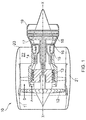
Figure 1 shows a ducted fan gas turbine; -
Figure 2 shows a schematic representation of an axial cross-section through a casing assembly surrounding a high pressure compressor according to a first embodiment of the present invention; -
Figure 3 shows an axial cross-section through a casing assembly according to a second embodiment of the present invention; and -
Figure 4 shows a schematic representation of an axial cross-section through a casing assembly surrounding a high pressure compressor according to a third embodiment of the present invention - As shown in
Figure 2 , a casing assembly 1 for surrounding a high pressure compressor (100) in a gas turbine engine comprises a radiallyinner casing 2 and a radiallyouter casing 3. - The
outer casing 3 extends the full length of the high pressure rotor which includes a high pressure compressor (100), a combustor (200) and a high pressure turbine (300). The rotor includes a shaft extending between an upstream (front) bearing 29 and a downstream (rear) bearing 30 along arotor axis 31. To reduce the weight/cost of the casing assembly, theinner casing 2 only extends to enclose the compressor; it does not surround the combustor i.e. the downstream axial end of theinner casing 2 is upstream of the downstream axial end of theouter casing 3. - An axial mounting
arrangement 4 between theinner casing 2 and theouter casing 3 comprises a radially outwards-directedannular flange 5 extending from theinner casing 2 and acircumferential groove 6 provided on saidouter casing 2. Thegroove 6 receives theannular flange 5 and theannular flange 5 is radially slidable within thegroove 6. - The axial clearance between the circumferential flange and the groove may be 0.05 ± 0.05 mm i.e. the flange may be substantially axially restrained within the circumferential groove.
- The
annular flange 5/circumferential groove 6 is coated/lined with a wear-resistant coating such as tungsten carbide cobalt. - The radially outer end 7 of the
annular flange 5 is spaced from the radially outer end 8 of thegroove 6 to ensure that there is no radial contact between theflange 5 and thegroove 6 as a result of distortion of theouter casing 3 by engine carcass loads. - The
annular groove 6 is defined within a radially inwards-directedannular element 9 on theinner casing 2. Theannular element 9 is defined by two annular radially outwards-directedplates inner casing 2. - The
annular element 9 depends from theouter casing 3 at a position where there is an axial plane where theouter casing 3 is parallel to the engine/rotor axis 31 during carcass bending. As can be seen inFigure 2 , this is the point of the change of direction of the deformation where there is a zero gradient i.e. the point along the deformedouter casing 3 where it is parallel to therotor centreline 31. This ensures that theinner casing 2 remains concentric with the rotor. - The casing assembly further comprises a
radial mounting arrangement 27 comprising a mountingsurface 28 on the inner casing which is mounted and axially slidable on a corresponding mounting surface depending from a frontbearing support structure 32 which connects theouter casing 3 to thefront rotor bearing 29. The mounting surface(s) 28 are coated with a wear-resistant coating such as tungsten carbide cobalt. - The
radial mounting arrangement 27 may further comprise an anti-rotation mechanism to prevent rotational motion of the inner casing as a result of aeroloads applied to the stator vanes in the high pressure compressor. -
Figure 3 shows a second embodiment which is similar to the first except in that the axial mounting arrangement 4' has a flange 5' depending radially inwards from the outer casing 3 (at a position where there is an axial plane where theouter casing 3 is parallel to the engine/rotor axis 31 during carcass bending) and a circumferential groove 6' provided on theinner casing 2. - The annular groove 6' is defined within a radially outwards-directed annular element 9' on the
inner casing 2. The annular element 9' is defined by two annular radially outwards-directedplates 20a', 20b' extending from theinner casing 2. These annular plates are axially spaced by aspacer portion 24. Theannular plates 20a', 20b' andspacer portion 24 are connected by an axially-extendingbolt 25. - In this embodiment, the inner casing comprises a plurality of
struts annular plate 20a', 20b'. Thestruts further strut 26c (which is also be angled relative to the engine/rotor axis) is provided to support thespacer portion 24. - In the embodiments shown in
Figure 2 and3 , as theouter casing 3 distorts as a result of carcass loads, theflange 5, 5' moves radially within thegroove 6, 6' without causing nay flexing of theinner casing 2. This allows theinner casing 2 to retain its circularity and thus its concentricity about therotor axis 31. -
Figure 4 shows a third embodiment of the present invention. - In this embodiment, the position of zero bending on the
outer casing 3 is axially downstream of the downstreamaxial end 33 of the inner casing 2 (such that an optimally positioned flange/groove arrangement shown inFigure 2 and3 cannot be formed), theaxial mounting arrangement 4" may comprise a fixed connection 34 (axially and radially fixed) between the inner andouter casing inner casing 2 andouter casing 3. - The flexible link element 35 is an apertured flange mounted the
inner casing 2 having, at its downstream axial end, an innercasing connection element 36 which is a radially-outwards extending flange. This innercasing connection element 36 is bolted to an outercasing connection element 37 which is a radially inwards depending flange to secure theinner casing 2 andouter casing 3 in a fixed axial and radial relationship. - In the embodiment shown in
Figure 4 , the radially flexible link element 35 flexes radially during movement of theouter casing 3 relative to theinner casing 2 i.e. it absorbs the radial deflection of theouter casing 3 without transferring it to theinner casing 2 thus allowing theinner casing 2 to retain its circularity and thus its concentricity about therotor axis 31. - While the invention has been described in conjunction with the exemplary embodiments described above, many equivalent modifications and variations will be apparent to those skilled in the art when given this disclosure. Accordingly, the exemplary embodiments of the invention set forth above are considered to be illustrative and not limiting. Various changes to the described embodiments may be made without departing from the spirit and scope of the invention.
- All references referred to above are hereby incorporated by reference.
Claims (15)
- A casing assembly (1) for a gas turbine engine (10) comprising:a radially inner casing (2);a radially outer casing (3); andan axial mounting arrangement (4, 4', 4") for mounting the inner casing and outer casing in a fixed axial relationship wherein the axial mounting arrangement allows radial movement of the outer casing relative to the inner casing, wherein:the outer casing has an axial extension portion which extends axially beyond the inner casing.
- A casing assembly according to claim 1, wherein:the casing assembly (1) is for a gas turbine engine (10) having a compressor (100) and a combustor (200); andthe radially inner casing (2) extends so as to surround the compressor (100) but not the combustor (200).
- A casing assembly according to claim 1 or claim 2, wherein the axial mounting arrangement (4, 4', 4") is the most axially downstream mounting arrangement that connects the radially inner casing (2) and the radially outer casing (3).
- A casing assembly according to any one of the preceding claims, wherein the casing assembly comprises mounting arrangements (4, 4', 4", 27) for connecting the radially inner casing (2) and the radially outer casing (3) at two and only two axial positions.
- A casing assembly according to claim 4, wherein the axial mounting arrangement (4, 4', 4") is provided at the more axially downstream position, and a radial mounting arrangement (27) is provided at the more axially upstream position, the radial mounting arrangement being for mounting the inner casing and outer casing in a fixed radial relationship whilst allowing axial movement of the inner casing relative to the outer casing.
- A casing assembly according to claim 5 wherein:the radial mounting arrangement is provided at or proximal the upstream axial end of the inner casing; and/orthe radial mounting arrangement comprises an anti-rotation mechanism to prevent rotation of the inner casing.
- A casing assembly according to any one of the preceding claims, wherein the axial mounting arrangement comprises either a radially inwards-directed annular flange (5') depending from the outer casing and a circumferential groove (6') provided on said inner casing or a radially outwards-directed annular flange (5) extending from the inner casing and a circumferential groove (6) provided on said outer casing, wherein the circumferential groove receives said annular flange and wherein the annular flange is radially slidable within said groove.
- A casing assembly according to claim 7 wherein the axial mounting arrangement comprises a radially inwards-directed annular flange depending from the outer casing and a circumferential groove provided on said inner casing and the radially inner end of the annular flange is spaced from the radially inner end of the groove.
- A casing assembly according to claim 7 wherein the axial mounting arrangement comprises a radially outwards-directed annular flange extending from the inner casing and a circumferential groove provided on said outer casing and the radially outer end of the annular flange is spaced from the radially outer end of the groove.
- A casing assembly according to any one of claims 7 to 9 wherein the flange or groove is provided on the outer casing at a position where there is an axial plane where the outer casing is parallel to the engine/rotor axis during bending of the outer casing.
- A casing assembly according to any one of claims 1 to 6, wherein the axial mounting arrangement comprises a fixed connection (34) between the inner and outer casing and a radially flexible link element (35) axially fixed between the inner casing and outer casing.
- A casing assembly according to claim 11 wherein the flexible link element is mounted on/forms part of the inner casing and has, at or proximal its downstream axial end, an inner casing connection element for forming the fixed connection with the outer casing.
- A gas turbine engine comprising:a casing assembly according to any one of claims 1 to 12;a high pressure compressor (100); anda high pressure turbine (200);wherein the radially inner casing and radially outer casing surrounds the high pressure compressor.
- A gas turbine engine according to claim 13 further comprising a combustor (300) wherein the inner casing does not surround the combustor.
- A gas turbine engine according to claim 14, wherein the axial extension portion which extends axially beyond the inner casing surrounds the combustor.
Applications Claiming Priority (1)
| Application Number | Priority Date | Filing Date | Title |
|---|---|---|---|
| GBGB1507647.4A GB201507647D0 (en) | 2015-05-05 | 2015-05-05 | Casing assembly |
Publications (2)
| Publication Number | Publication Date |
|---|---|
| EP3095969A1 true EP3095969A1 (en) | 2016-11-23 |
| EP3095969B1 EP3095969B1 (en) | 2020-02-26 |
Family
ID=53489131
Family Applications (1)
| Application Number | Title | Priority Date | Filing Date |
|---|---|---|---|
| EP16166852.0A Active EP3095969B1 (en) | 2015-05-05 | 2016-04-25 | Casing assembly |
Country Status (3)
| Country | Link |
|---|---|
| US (1) | US10196938B2 (en) |
| EP (1) | EP3095969B1 (en) |
| GB (1) | GB201507647D0 (en) |
Cited By (1)
| Publication number | Priority date | Publication date | Assignee | Title |
|---|---|---|---|---|
| EP3546708A1 (en) * | 2018-03-29 | 2019-10-02 | Rolls-Royce plc | Turbine engine |
Families Citing this family (4)
| Publication number | Priority date | Publication date | Assignee | Title |
|---|---|---|---|---|
| EP3286410B1 (en) * | 2015-04-24 | 2021-06-02 | Nuovo Pignone Tecnologie Srl | Gas turbine engine having a casing provided with cooling fins |
| US20180034350A1 (en) * | 2016-08-01 | 2018-02-01 | General Electric Company | Method for compensating for thermal distortion of a part |
| US10704414B2 (en) * | 2017-03-10 | 2020-07-07 | General Electric Company | Airfoil containment structure including a notched and tapered inner shell |
| CN114483223B (en) * | 2021-12-27 | 2023-07-18 | 东方电气集团东方汽轮机有限公司 | A temperature balance structure of the cylindrical cylinder of steam turbine |
Citations (3)
| Publication number | Priority date | Publication date | Assignee | Title |
|---|---|---|---|---|
| GB2114661A (en) * | 1980-10-21 | 1983-08-24 | Rolls Royce | Casing structure for a gas turbine engine |
| GB2168755A (en) * | 1984-12-08 | 1986-06-25 | Rolls Royce | Improvements in or relating to gas turbine engines |
| US20100242494A1 (en) * | 2009-03-24 | 2010-09-30 | Rolls-Royce Plc | Casing arrangement |
Family Cites Families (4)
| Publication number | Priority date | Publication date | Assignee | Title |
|---|---|---|---|---|
| GB191306077A (en) | 1912-03-12 | 1913-05-15 | Ljungstroms Angturbin Ab | Improvements in Steam Turbines. |
| BE786674A (en) | 1971-07-26 | 1973-01-25 | Westinghouse Electric Corp | MULTI-ENCLOSURE TURBINE |
| DE102004016222A1 (en) * | 2004-03-26 | 2005-10-06 | Rolls-Royce Deutschland Ltd & Co Kg | Arrangement for automatic running gap adjustment in a two-stage or multi-stage turbine |
| EP2530249A1 (en) * | 2011-05-30 | 2012-12-05 | Siemens Aktiengesellschaft | Piston seal ring |
-
2015
- 2015-05-05 GB GBGB1507647.4A patent/GB201507647D0/en not_active Ceased
-
2016
- 2016-04-25 EP EP16166852.0A patent/EP3095969B1/en active Active
- 2016-04-26 US US15/138,946 patent/US10196938B2/en not_active Expired - Fee Related
Patent Citations (3)
| Publication number | Priority date | Publication date | Assignee | Title |
|---|---|---|---|---|
| GB2114661A (en) * | 1980-10-21 | 1983-08-24 | Rolls Royce | Casing structure for a gas turbine engine |
| GB2168755A (en) * | 1984-12-08 | 1986-06-25 | Rolls Royce | Improvements in or relating to gas turbine engines |
| US20100242494A1 (en) * | 2009-03-24 | 2010-09-30 | Rolls-Royce Plc | Casing arrangement |
Cited By (1)
| Publication number | Priority date | Publication date | Assignee | Title |
|---|---|---|---|---|
| EP3546708A1 (en) * | 2018-03-29 | 2019-10-02 | Rolls-Royce plc | Turbine engine |
Also Published As
| Publication number | Publication date |
|---|---|
| GB201507647D0 (en) | 2015-06-17 |
| US20170058699A1 (en) | 2017-03-02 |
| US10196938B2 (en) | 2019-02-05 |
| EP3095969B1 (en) | 2020-02-26 |
Similar Documents
| Publication | Publication Date | Title |
|---|---|---|
| US10301960B2 (en) | Shroud assembly for gas turbine engine | |
| US10196938B2 (en) | Casing assembly | |
| CN104081007B (en) | A support component of turbine gear drive framework | |
| EP1008726A2 (en) | Fan decoupler system for a gas turbine engine | |
| US10738923B2 (en) | Flexural spring-energized interface for bellowed ball-joint assemblies for controlled rotational constraint | |
| US10138745B2 (en) | Sealing system with two rows of complementary sealing elements | |
| US12140035B2 (en) | Turbine engine with a shroud assembly | |
| US20140050567A1 (en) | Synchronizing ring surge bumper | |
| US10408068B2 (en) | Fan blade dovetail and spacer | |
| EP2256303B1 (en) | A casing arrangement | |
| US9856740B2 (en) | Tip-controlled integrally bladed rotor for gas turbine engine | |
| US2917275A (en) | Turbo machines having adjustable guide blades | |
| CN113277094A (en) | Aircraft and propulsion engine mounting system | |
| EP3536902B1 (en) | Gas turbine engine component | |
| US20210062728A1 (en) | Actuation Assembly for Concentric Variable Stator Vanes | |
| US12006829B1 (en) | Seal member support system for a gas turbine engine | |
| US20180087395A1 (en) | Gas turbine engine | |
| US12618369B2 (en) | Propulsion engine and cowl | |
| US20220119123A1 (en) | Propulsion engine and cowl | |
| US20260049560A1 (en) | Outer air seal (oas) with improved mating with first stage casing | |
| US12326089B2 (en) | Seal assembly for a gas turbine engine | |
| GB2562157A (en) | Mitigation of effects of fan blade off in a gas turbine engine |
Legal Events
| Date | Code | Title | Description |
|---|---|---|---|
| PUAI | Public reference made under article 153(3) epc to a published international application that has entered the european phase |
Free format text: ORIGINAL CODE: 0009012 |
|
| AK | Designated contracting states |
Kind code of ref document: A1 Designated state(s): AL AT BE BG CH CY CZ DE DK EE ES FI FR GB GR HR HU IE IS IT LI LT LU LV MC MK MT NL NO PL PT RO RS SE SI SK SM TR |
|
| AX | Request for extension of the european patent |
Extension state: BA ME |
|
| STAA | Information on the status of an ep patent application or granted ep patent |
Free format text: STATUS: REQUEST FOR EXAMINATION WAS MADE |
|
| 17P | Request for examination filed |
Effective date: 20170505 |
|
| RBV | Designated contracting states (corrected) |
Designated state(s): AL AT BE BG CH CY CZ DE DK EE ES FI FR GB GR HR HU IE IS IT LI LT LU LV MC MK MT NL NO PL PT RO RS SE SI SK SM TR |
|
| STAA | Information on the status of an ep patent application or granted ep patent |
Free format text: STATUS: EXAMINATION IS IN PROGRESS |
|
| 17Q | First examination report despatched |
Effective date: 20180516 |
|
| REG | Reference to a national code |
Ref country code: DE Ref legal event code: R079 Ref document number: 602016030409 Country of ref document: DE Free format text: PREVIOUS MAIN CLASS: F01D0025240000 Ipc: F01D0025260000 |
|
| RIC1 | Information provided on ipc code assigned before grant |
Ipc: F01D 25/24 20060101ALI20190912BHEP Ipc: F01D 25/26 20060101AFI20190912BHEP |
|
| GRAP | Despatch of communication of intention to grant a patent |
Free format text: ORIGINAL CODE: EPIDOSNIGR1 |
|
| STAA | Information on the status of an ep patent application or granted ep patent |
Free format text: STATUS: GRANT OF PATENT IS INTENDED |
|
| GRAS | Grant fee paid |
Free format text: ORIGINAL CODE: EPIDOSNIGR3 |
|
| INTG | Intention to grant announced |
Effective date: 20200102 |
|
| RIN1 | Information on inventor provided before grant (corrected) |
Inventor name: BOOTH, RICHARD Inventor name: KNIGHT, MARK |
|
| GRAA | (expected) grant |
Free format text: ORIGINAL CODE: 0009210 |
|
| STAA | Information on the status of an ep patent application or granted ep patent |
Free format text: STATUS: THE PATENT HAS BEEN GRANTED |
|
| AK | Designated contracting states |
Kind code of ref document: B1 Designated state(s): AL AT BE BG CH CY CZ DE DK EE ES FI FR GB GR HR HU IE IS IT LI LT LU LV MC MK MT NL NO PL PT RO RS SE SI SK SM TR |
|
| RAP1 | Party data changed (applicant data changed or rights of an application transferred) |
Owner name: ROLLS-ROYCE PLC |
|
| REG | Reference to a national code |
Ref country code: GB Ref legal event code: FG4D |
|
| REG | Reference to a national code |
Ref country code: CH Ref legal event code: EP |
|
| REG | Reference to a national code |
Ref country code: AT Ref legal event code: REF Ref document number: 1237879 Country of ref document: AT Kind code of ref document: T Effective date: 20200315 |
|
| REG | Reference to a national code |
Ref country code: IE Ref legal event code: FG4D |
|
| REG | Reference to a national code |
Ref country code: DE Ref legal event code: R096 Ref document number: 602016030409 Country of ref document: DE |
|
| PG25 | Lapsed in a contracting state [announced via postgrant information from national office to epo] |
Ref country code: RS Free format text: LAPSE BECAUSE OF FAILURE TO SUBMIT A TRANSLATION OF THE DESCRIPTION OR TO PAY THE FEE WITHIN THE PRESCRIBED TIME-LIMIT Effective date: 20200226 Ref country code: NO Free format text: LAPSE BECAUSE OF FAILURE TO SUBMIT A TRANSLATION OF THE DESCRIPTION OR TO PAY THE FEE WITHIN THE PRESCRIBED TIME-LIMIT Effective date: 20200526 Ref country code: FI Free format text: LAPSE BECAUSE OF FAILURE TO SUBMIT A TRANSLATION OF THE DESCRIPTION OR TO PAY THE FEE WITHIN THE PRESCRIBED TIME-LIMIT Effective date: 20200226 |
|
| PGFP | Annual fee paid to national office [announced via postgrant information from national office to epo] |
Ref country code: FR Payment date: 20200429 Year of fee payment: 5 |
|
| REG | Reference to a national code |
Ref country code: NL Ref legal event code: MP Effective date: 20200226 |
|
| REG | Reference to a national code |
Ref country code: LT Ref legal event code: MG4D |
|
| PG25 | Lapsed in a contracting state [announced via postgrant information from national office to epo] |
Ref country code: BG Free format text: LAPSE BECAUSE OF FAILURE TO SUBMIT A TRANSLATION OF THE DESCRIPTION OR TO PAY THE FEE WITHIN THE PRESCRIBED TIME-LIMIT Effective date: 20200526 Ref country code: LV Free format text: LAPSE BECAUSE OF FAILURE TO SUBMIT A TRANSLATION OF THE DESCRIPTION OR TO PAY THE FEE WITHIN THE PRESCRIBED TIME-LIMIT Effective date: 20200226 Ref country code: HR Free format text: LAPSE BECAUSE OF FAILURE TO SUBMIT A TRANSLATION OF THE DESCRIPTION OR TO PAY THE FEE WITHIN THE PRESCRIBED TIME-LIMIT Effective date: 20200226 Ref country code: GR Free format text: LAPSE BECAUSE OF FAILURE TO SUBMIT A TRANSLATION OF THE DESCRIPTION OR TO PAY THE FEE WITHIN THE PRESCRIBED TIME-LIMIT Effective date: 20200527 Ref country code: IS Free format text: LAPSE BECAUSE OF FAILURE TO SUBMIT A TRANSLATION OF THE DESCRIPTION OR TO PAY THE FEE WITHIN THE PRESCRIBED TIME-LIMIT Effective date: 20200626 Ref country code: SE Free format text: LAPSE BECAUSE OF FAILURE TO SUBMIT A TRANSLATION OF THE DESCRIPTION OR TO PAY THE FEE WITHIN THE PRESCRIBED TIME-LIMIT Effective date: 20200226 |
|
| PGFP | Annual fee paid to national office [announced via postgrant information from national office to epo] |
Ref country code: GB Payment date: 20200429 Year of fee payment: 5 |
|
| PG25 | Lapsed in a contracting state [announced via postgrant information from national office to epo] |
Ref country code: NL Free format text: LAPSE BECAUSE OF FAILURE TO SUBMIT A TRANSLATION OF THE DESCRIPTION OR TO PAY THE FEE WITHIN THE PRESCRIBED TIME-LIMIT Effective date: 20200226 |
|
| PG25 | Lapsed in a contracting state [announced via postgrant information from national office to epo] |
Ref country code: ES Free format text: LAPSE BECAUSE OF FAILURE TO SUBMIT A TRANSLATION OF THE DESCRIPTION OR TO PAY THE FEE WITHIN THE PRESCRIBED TIME-LIMIT Effective date: 20200226 Ref country code: PT Free format text: LAPSE BECAUSE OF FAILURE TO SUBMIT A TRANSLATION OF THE DESCRIPTION OR TO PAY THE FEE WITHIN THE PRESCRIBED TIME-LIMIT Effective date: 20200719 Ref country code: EE Free format text: LAPSE BECAUSE OF FAILURE TO SUBMIT A TRANSLATION OF THE DESCRIPTION OR TO PAY THE FEE WITHIN THE PRESCRIBED TIME-LIMIT Effective date: 20200226 Ref country code: DK Free format text: LAPSE BECAUSE OF FAILURE TO SUBMIT A TRANSLATION OF THE DESCRIPTION OR TO PAY THE FEE WITHIN THE PRESCRIBED TIME-LIMIT Effective date: 20200226 Ref country code: SM Free format text: LAPSE BECAUSE OF FAILURE TO SUBMIT A TRANSLATION OF THE DESCRIPTION OR TO PAY THE FEE WITHIN THE PRESCRIBED TIME-LIMIT Effective date: 20200226 Ref country code: SK Free format text: LAPSE BECAUSE OF FAILURE TO SUBMIT A TRANSLATION OF THE DESCRIPTION OR TO PAY THE FEE WITHIN THE PRESCRIBED TIME-LIMIT Effective date: 20200226 Ref country code: CZ Free format text: LAPSE BECAUSE OF FAILURE TO SUBMIT A TRANSLATION OF THE DESCRIPTION OR TO PAY THE FEE WITHIN THE PRESCRIBED TIME-LIMIT Effective date: 20200226 Ref country code: RO Free format text: LAPSE BECAUSE OF FAILURE TO SUBMIT A TRANSLATION OF THE DESCRIPTION OR TO PAY THE FEE WITHIN THE PRESCRIBED TIME-LIMIT Effective date: 20200226 Ref country code: LT Free format text: LAPSE BECAUSE OF FAILURE TO SUBMIT A TRANSLATION OF THE DESCRIPTION OR TO PAY THE FEE WITHIN THE PRESCRIBED TIME-LIMIT Effective date: 20200226 |
|
| PGFP | Annual fee paid to national office [announced via postgrant information from national office to epo] |
Ref country code: DE Payment date: 20200629 Year of fee payment: 5 |
|
| REG | Reference to a national code |
Ref country code: AT Ref legal event code: MK05 Ref document number: 1237879 Country of ref document: AT Kind code of ref document: T Effective date: 20200226 |
|
| REG | Reference to a national code |
Ref country code: DE Ref legal event code: R097 Ref document number: 602016030409 Country of ref document: DE |
|
| PG25 | Lapsed in a contracting state [announced via postgrant information from national office to epo] |
Ref country code: MC Free format text: LAPSE BECAUSE OF FAILURE TO SUBMIT A TRANSLATION OF THE DESCRIPTION OR TO PAY THE FEE WITHIN THE PRESCRIBED TIME-LIMIT Effective date: 20200226 |
|
| REG | Reference to a national code |
Ref country code: CH Ref legal event code: PL |
|
| PLBE | No opposition filed within time limit |
Free format text: ORIGINAL CODE: 0009261 |
|
| STAA | Information on the status of an ep patent application or granted ep patent |
Free format text: STATUS: NO OPPOSITION FILED WITHIN TIME LIMIT |
|
| PG25 | Lapsed in a contracting state [announced via postgrant information from national office to epo] |
Ref country code: IT Free format text: LAPSE BECAUSE OF FAILURE TO SUBMIT A TRANSLATION OF THE DESCRIPTION OR TO PAY THE FEE WITHIN THE PRESCRIBED TIME-LIMIT Effective date: 20200226 Ref country code: CH Free format text: LAPSE BECAUSE OF NON-PAYMENT OF DUE FEES Effective date: 20200430 Ref country code: AT Free format text: LAPSE BECAUSE OF FAILURE TO SUBMIT A TRANSLATION OF THE DESCRIPTION OR TO PAY THE FEE WITHIN THE PRESCRIBED TIME-LIMIT Effective date: 20200226 Ref country code: LI Free format text: LAPSE BECAUSE OF NON-PAYMENT OF DUE FEES Effective date: 20200430 Ref country code: LU Free format text: LAPSE BECAUSE OF NON-PAYMENT OF DUE FEES Effective date: 20200425 |
|
| 26N | No opposition filed |
Effective date: 20201127 |
|
| REG | Reference to a national code |
Ref country code: BE Ref legal event code: MM Effective date: 20200430 |
|
| PG25 | Lapsed in a contracting state [announced via postgrant information from national office to epo] |
Ref country code: PL Free format text: LAPSE BECAUSE OF FAILURE TO SUBMIT A TRANSLATION OF THE DESCRIPTION OR TO PAY THE FEE WITHIN THE PRESCRIBED TIME-LIMIT Effective date: 20200226 Ref country code: BE Free format text: LAPSE BECAUSE OF NON-PAYMENT OF DUE FEES Effective date: 20200430 Ref country code: SI Free format text: LAPSE BECAUSE OF FAILURE TO SUBMIT A TRANSLATION OF THE DESCRIPTION OR TO PAY THE FEE WITHIN THE PRESCRIBED TIME-LIMIT Effective date: 20200226 |
|
| PG25 | Lapsed in a contracting state [announced via postgrant information from national office to epo] |
Ref country code: IE Free format text: LAPSE BECAUSE OF NON-PAYMENT OF DUE FEES Effective date: 20200425 |
|
| REG | Reference to a national code |
Ref country code: DE Ref legal event code: R119 Ref document number: 602016030409 Country of ref document: DE |
|
| GBPC | Gb: european patent ceased through non-payment of renewal fee |
Effective date: 20210425 |
|
| PG25 | Lapsed in a contracting state [announced via postgrant information from national office to epo] |
Ref country code: DE Free format text: LAPSE BECAUSE OF NON-PAYMENT OF DUE FEES Effective date: 20211103 Ref country code: GB Free format text: LAPSE BECAUSE OF NON-PAYMENT OF DUE FEES Effective date: 20210425 Ref country code: FR Free format text: LAPSE BECAUSE OF NON-PAYMENT OF DUE FEES Effective date: 20210430 |
|
| PG25 | Lapsed in a contracting state [announced via postgrant information from national office to epo] |
Ref country code: TR Free format text: LAPSE BECAUSE OF FAILURE TO SUBMIT A TRANSLATION OF THE DESCRIPTION OR TO PAY THE FEE WITHIN THE PRESCRIBED TIME-LIMIT Effective date: 20200226 Ref country code: MT Free format text: LAPSE BECAUSE OF FAILURE TO SUBMIT A TRANSLATION OF THE DESCRIPTION OR TO PAY THE FEE WITHIN THE PRESCRIBED TIME-LIMIT Effective date: 20200226 Ref country code: CY Free format text: LAPSE BECAUSE OF FAILURE TO SUBMIT A TRANSLATION OF THE DESCRIPTION OR TO PAY THE FEE WITHIN THE PRESCRIBED TIME-LIMIT Effective date: 20200226 |
|
| PG25 | Lapsed in a contracting state [announced via postgrant information from national office to epo] |
Ref country code: MK Free format text: LAPSE BECAUSE OF FAILURE TO SUBMIT A TRANSLATION OF THE DESCRIPTION OR TO PAY THE FEE WITHIN THE PRESCRIBED TIME-LIMIT Effective date: 20200226 Ref country code: AL Free format text: LAPSE BECAUSE OF FAILURE TO SUBMIT A TRANSLATION OF THE DESCRIPTION OR TO PAY THE FEE WITHIN THE PRESCRIBED TIME-LIMIT Effective date: 20200226 |