EP3095703A1 - Environmental cooling systems for aircraft - Google Patents
Environmental cooling systems for aircraft Download PDFInfo
- Publication number
- EP3095703A1 EP3095703A1 EP16169218.1A EP16169218A EP3095703A1 EP 3095703 A1 EP3095703 A1 EP 3095703A1 EP 16169218 A EP16169218 A EP 16169218A EP 3095703 A1 EP3095703 A1 EP 3095703A1
- Authority
- EP
- European Patent Office
- Prior art keywords
- ecs
- thrust
- engine
- bleed air
- aircraft
- Prior art date
- Legal status (The legal status is an assumption and is not a legal conclusion. Google has not performed a legal analysis and makes no representation as to the accuracy of the status listed.)
- Granted
Links
Images



Classifications
-
- B—PERFORMING OPERATIONS; TRANSPORTING
- B64—AIRCRAFT; AVIATION; COSMONAUTICS
- B64D—EQUIPMENT FOR FITTING IN OR TO AIRCRAFT; FLIGHT SUITS; PARACHUTES; ARRANGEMENT OR MOUNTING OF POWER PLANTS OR PROPULSION TRANSMISSIONS IN AIRCRAFT
- B64D13/00—Arrangements or adaptations of air-treatment apparatus for aircraft crew or passengers, or freight space
- B64D13/06—Arrangements or adaptations of air-treatment apparatus for aircraft crew or passengers, or freight space the air being conditioned
-
- B—PERFORMING OPERATIONS; TRANSPORTING
- B64—AIRCRAFT; AVIATION; COSMONAUTICS
- B64D—EQUIPMENT FOR FITTING IN OR TO AIRCRAFT; FLIGHT SUITS; PARACHUTES; ARRANGEMENT OR MOUNTING OF POWER PLANTS OR PROPULSION TRANSMISSIONS IN AIRCRAFT
- B64D31/00—Power plant control systems; Arrangement of power plant control systems in aircraft
- B64D31/02—Initiating means
- B64D31/06—Initiating means actuated automatically
-
- F—MECHANICAL ENGINEERING; LIGHTING; HEATING; WEAPONS; BLASTING
- F02—COMBUSTION ENGINES; HOT-GAS OR COMBUSTION-PRODUCT ENGINE PLANTS
- F02C—GAS-TURBINE PLANTS; AIR INTAKES FOR JET-PROPULSION PLANTS; CONTROLLING FUEL SUPPLY IN AIR-BREATHING JET-PROPULSION PLANTS
- F02C6/00—Plural gas-turbine plants; Combinations of gas-turbine plants with other apparatus; Adaptations of gas-turbine plants for special use
- F02C6/04—Gas-turbine plants providing heated or pressurised working fluid for other apparatus, e.g. without mechanical power output
- F02C6/06—Gas-turbine plants providing heated or pressurised working fluid for other apparatus, e.g. without mechanical power output providing compressed gas
- F02C6/08—Gas-turbine plants providing heated or pressurised working fluid for other apparatus, e.g. without mechanical power output providing compressed gas the gas being bled from the gas-turbine compressor
-
- F—MECHANICAL ENGINEERING; LIGHTING; HEATING; WEAPONS; BLASTING
- F02—COMBUSTION ENGINES; HOT-GAS OR COMBUSTION-PRODUCT ENGINE PLANTS
- F02C—GAS-TURBINE PLANTS; AIR INTAKES FOR JET-PROPULSION PLANTS; CONTROLLING FUEL SUPPLY IN AIR-BREATHING JET-PROPULSION PLANTS
- F02C9/00—Controlling gas-turbine plants; Controlling fuel supply in air- breathing jet-propulsion plants
- F02C9/16—Control of working fluid flow
- F02C9/18—Control of working fluid flow by bleeding, bypassing or acting on variable working fluid interconnections between turbines or compressors or their stages
-
- B—PERFORMING OPERATIONS; TRANSPORTING
- B64—AIRCRAFT; AVIATION; COSMONAUTICS
- B64D—EQUIPMENT FOR FITTING IN OR TO AIRCRAFT; FLIGHT SUITS; PARACHUTES; ARRANGEMENT OR MOUNTING OF POWER PLANTS OR PROPULSION TRANSMISSIONS IN AIRCRAFT
- B64D13/00—Arrangements or adaptations of air-treatment apparatus for aircraft crew or passengers, or freight space
- B64D13/06—Arrangements or adaptations of air-treatment apparatus for aircraft crew or passengers, or freight space the air being conditioned
- B64D2013/0603—Environmental Control Systems
- B64D2013/0618—Environmental Control Systems with arrangements for reducing or managing bleed air, using another air source, e.g. ram air
-
- B—PERFORMING OPERATIONS; TRANSPORTING
- B64—AIRCRAFT; AVIATION; COSMONAUTICS
- B64D—EQUIPMENT FOR FITTING IN OR TO AIRCRAFT; FLIGHT SUITS; PARACHUTES; ARRANGEMENT OR MOUNTING OF POWER PLANTS OR PROPULSION TRANSMISSIONS IN AIRCRAFT
- B64D13/00—Arrangements or adaptations of air-treatment apparatus for aircraft crew or passengers, or freight space
- B64D13/06—Arrangements or adaptations of air-treatment apparatus for aircraft crew or passengers, or freight space the air being conditioned
- B64D2013/0603—Environmental Control Systems
- B64D2013/064—Environmental Control Systems comprising more than one system, e.g. dual systems
-
- F—MECHANICAL ENGINEERING; LIGHTING; HEATING; WEAPONS; BLASTING
- F05—INDEXING SCHEMES RELATING TO ENGINES OR PUMPS IN VARIOUS SUBCLASSES OF CLASSES F01-F04
- F05D—INDEXING SCHEME FOR ASPECTS RELATING TO NON-POSITIVE-DISPLACEMENT MACHINES OR ENGINES, GAS-TURBINES OR JET-PROPULSION PLANTS
- F05D2220/00—Application
- F05D2220/30—Application in turbines
- F05D2220/32—Application in turbines in gas turbines
-
- Y—GENERAL TAGGING OF NEW TECHNOLOGICAL DEVELOPMENTS; GENERAL TAGGING OF CROSS-SECTIONAL TECHNOLOGIES SPANNING OVER SEVERAL SECTIONS OF THE IPC; TECHNICAL SUBJECTS COVERED BY FORMER USPC CROSS-REFERENCE ART COLLECTIONS [XRACs] AND DIGESTS
- Y02—TECHNOLOGIES OR APPLICATIONS FOR MITIGATION OR ADAPTATION AGAINST CLIMATE CHANGE
- Y02T—CLIMATE CHANGE MITIGATION TECHNOLOGIES RELATED TO TRANSPORTATION
- Y02T50/00—Aeronautics or air transport
- Y02T50/50—On board measures aiming to increase energy efficiency
Definitions
- the present disclosure relates to environmental cooling systems (ECS) for aircraft, more specifically to systems for providing suitable air bleeding pressure.
- ECS environmental cooling systems
- ECS environmental control systems
- an environmental control system (ECS) for a multi-engine aircraft includes a controller configured to switch the ECS between a plurality of operating modes.
- the plurality of operating modes includes a first operating mode configured to receive bleed air from each engine of the aircraft in a first environmental condition, wherein the pressure of the bleed air is about equal from each engine.
- the plurality of operating modes includes a second operating mode configured to receive bleed air from at least one engine of the aircraft in a second environmental condition, wherein the pressure of the bleed air is different between at least two engines.
- the controller can be operatively connected to a thrust controller to cause engine thrust to increase in at least one engine and to reduce thrust from at least one other engine to maintain a constant total thrust when the ECS is in the second operating mode.
- bleed air from at least one engine can shut off in the second environmental condition.
- the controller can be operatively connected to the thrust controller to increase or reduce thrust symmetrically to prevent asymmetric thrust induced yaw.
- the system may additionally and/or alternatively include a plurality of ECS packs, each ECS pack connected to a respective one of the engines, wherein at least one of the plurality of ECS packs can be a mode changing ECS pack that is operative to change from a first cooling mode in the first operational mode to a second cooling mode in the second operational mode, wherein the second cooling mode can allow the ECS pack to operate with higher bleed air pressure than the first cooling mode.
- the plurality of ECS packs may additionally and/or alternatively include two mode changing packs connected to symmetric engines, and wherein two single mode ECS packs are connected to the remaining engines.
- each ECS pack may additionally and/or alternatively include a heat exchanger operative to cool the bleed air.
- the single mode ECS packs can be configured to shut off bleed air from their respective engines when the ECS is in the second operating mode.
- an aircraft can include a plurality of engines and an ECS as described in any of the foregoing embodiments above.
- an aircraft comprising: a plurality of engines; and an environmental control system (ECS), comprising: a controller configured to switch the ECS between a plurality of operating modes, the plurality of operating modes comprising: a first operating mode configured to receive bleed air from each engine of the aircraft in a first environmental condition, wherein the pressure of the bleed air is about equal from each engine; and a second operating mode configured to receive bleed air from at least one engine of the aircraft in a second environmental condition, wherein the pressure of the bleed air is different between at least two engines.
- ECS environmental control system
- the controller may be operatively connected to a thrust controller to cause engine thrust to increase in at least one engine and to reduce thrust from at least one other engine to maintain a constant total thrust when the ECS is in the second operating mode.
- bleed air from at least one engine may be shut off in the second environmental condition.
- a method for supplying pressurized air to an aircraft includes bleeding bleed air from a portion of a turbomachine of the aircraft and increasing a thrust output of the turbomachine to increase a pressure of the bleed air in a predetermined environmental condition.
- the turbomachine can be a first turbomachine and the method can further include reducing a thrust output of a second turbomachine of the aircraft to maintain a constant total thrust.
- increasing the thrust output can include increasing the thrust output of a first turbomachine and a second turbomachine that is symmetrically located relative to the first turbomachine.
- the thrust output of the first and second turbomachines can be increased by about an equal amount to prevent asymmetric thrust induced yaw, e.g., in a four engine system.
- the method may additionally and/or alternatively include reducing a thrust output of a third turbomachine of the aircraft to maintain a constant total thrust.
- reducing the thrust output may additionally and/or alternatively include reducing the thrust output of fourth turbomachine that is symmetrically located relative to the third turbomachine to prevent asymmetric thrust induced yaw.
- the method may additionally and/or alternatively include switching modes of an environmental control system (ECS) from a first operating mode configured to receive bleed air from each engine of the aircraft in a first environmental condition, wherein the pressure of the bleed air is about equal from each engine, to a second operating mode configured to receive bleed air from at least one engine of the aircraft in a second environmental condition, wherein the pressure of the bleed air is different between at least two engines.
- ECS environmental control system
- switching modes of the ECS may additionally and/or alternatively include switching at least one ECS pack from a first cooling mode to a second cooling mode.
- switching modes of the ECS may additionally and/or alternatively include maintaining a constant cooling mode in at least one ECS pack.
- FIG. 2A an illustrative view of an embodiment of an environmental control system in accordance with the disclosure is shown in Fig. 2A and is designated generally by reference character 200.
- FIGs. 1 and 2B Other embodiments and/or aspects of this disclosure are shown in Figs. 1 and 2B .
- the systems and methods described herein can be used to improve the efficiency of environmental control systems.
- Fig. 1 schematically illustrates a gas turbine engine 20.
- the gas turbine engine 20 is disclosed herein as a two-spool turbofan that generally incorporates a fan section 22, a compressor section 24, a combustor section 26 and a turbine section 28.
- Alternative engines might include an augmentor section (not shown) among other systems or features.
- the fan section 22 drives air along a bypass flow path B in a bypass duct defined within a nacelle 15, while the compressor section 24 drives air along a core flow path C for compression and communication into the combustor section 26 then expansion through the turbine section 28.
- an environmental control system (ECS) 200 for a multi- engine aircraft includes a controller 201 configured to switch the ECS 200 between a plurality of operating modes.
- the controller 201 can include any suitable hardware and/or software configured to change modes of the ECS 200 as is understood by those having ordinary skill in the art.
- the plurality of operating modes includes a first operating mode (e.g., as shown in Fig. 2A ) such that the ECS 200 is configured to receive bleed air from each engine 209a, 209b, 209c, 209d of the four-engine aircraft in a first environmental condition and where the pressure of the bleed air is about equal from each engine 209a, 209b, 209c, 209d.
- a first operating mode e.g., as shown in Fig. 2A
- the ECS 200 is configured to receive bleed air from each engine 209a, 209b, 209c, 209d of the four-engine aircraft in a first environmental condition and where the pressure of the bleed air is about equal from each engine 209a, 209b, 209c, 209d.
- engines 209a and 209b are physically closer to the aircraft fuselage than engines 209c and 209d, which is why the engines are shown in Figs. 2A and 2B as being in the order of 209d, 209
- the plurality of operating modes also includes a second operating mode (e.g., as shown in Fig. 2B ) such that the ECS 200 is configured to receive bleed air from at least one engine 209a, 209b of the aircraft in a second environmental condition and where the pressure of the bleed air is different between at least two engines (e.g., engine 209a can provide higher pressure bleed whereas engine 209c can provide no bleed air or reduced pressure bleed air).
- a second operating mode e.g., as shown in Fig. 2B
- the ECS 200 is configured to receive bleed air from at least one engine 209a, 209b of the aircraft in a second environmental condition and where the pressure of the bleed air is different between at least two engines (e.g., engine 209a can provide higher pressure bleed whereas engine 209c can provide no bleed air or reduced pressure bleed air).
- the controller 201 can be operatively connected to a thrust controller 300.
- the thrust controller 300 can be any suitable controller (e.g., a throttle mechanism, a full authority digital engine control (FADEC)) that can connect to each engine 209a, 209b, 209c, 209d and can control the thrust of each engine 209a, 209b, 209c, 209d, as is understood by those having ordinary skill in the art.
- FADEC full authority digital engine control
- the controller 201 can command the thrust controller 300 to cause engine thrust to increase in at least one engine (e.g., engines 209a, 209b) when the ECS 200 is in the second operating mode. Similarly, the controller 201 can command the thrust controller 300 to reduce thrust from at least one other engine (e.g., engines 209c, 209d) to maintain a constant total thrust when the ECS 200 is in the second operating mode.
- engine thrust e.g., engines 209a, 209b
- the controller 201 can command the thrust controller 300 to reduce thrust from at least one other engine (e.g., engines 209c, 209d) to maintain a constant total thrust when the ECS 200 is in the second operating mode.
- thrust must be reduced in an equal amount (e.g., in engines 209c, 209d) to the amount that thrust in increased in the at least one engine (e.g., engines 209a, 209b).
- the controller 201 can command the thrust controller 300 to increase or reduce thrust symmetrically to prevent asymmetric thrust induced yaw.
- engines 209a and 209b can increase thrust in about equal amounts and/or engines 209c and 209d can reduce thrust in about equal amounts which would prevent or reduce yaw from asymmetric thrust.
- the thrust can be asymmetrically modified inducing a yaw, and/or that the controller 201 can communicate with a flight control system (not shown) to trim the rudder automatically to the required amount. It is contemplated that even in the rudder trimmed scenario, e.g., for a two engine aircraft, that the overall efficiency of the system will be improved because of how relatively little time in that scenario would be required when compared to the total operating time of the aircraft.
- the system 200 can further include a plurality of ECS packs 203, 205, each ECS pack 203, 205 is connected to an engine 209a, 209b, 209c, 209d through a suitable fluid circuit 207.
- Each ECS pack 203, 205 also connects to the aircraft (e.g., the cabin and/or the cockpit) to supply pressurized and/or cooled air thereto (this connection is not shown in the drawings).
- at least one of the plurality of ECS packs 203, 205 can be a mode changing ECS pack 203 that is operative to change from a first cooling mode in the first operational mode (e.g., as shown in Fig. 2A ) to a second cooling mode in the second operational mode (e.g., as shown in Fig. 2B ).
- the second cooling mode can allow each mode changing ECS pack 203 to operate with higher bleed air pressure than the first cooling mode such that an increase in thrust (and thus bleed air pressure) from an engine (e.g., engines 209a, 209b) can be tolerated.
- each mode changing ECS pack 203 can draw bleed air from the high pressure compressor (either independently of a low pressure compressor bleed or in conjunction therewith).
- each single mode ECS pack can shut off bleed flow from their respective engine to maintain suitable total pressure within the ECS 200.
- the controller 201 can be operatively connected to the mode changing ECS packs 203 to communicate with the ECS packs 203 and/or to cause the ECS packs 203 to change between cooling modes. While a single controller 201 is shown separate from the ECS packs 203, it is contemplated that the controller 201 can be an internal component of each mode changing ECS pack 203 and/or that multiple controllers 201 can exist (e.g., a controller 201 for each ECS pack 203).
- the controller 201 can change the operating mode of the ECS 200 by virtue of changing the cooling mode of one or more of the ECS packs 203 as is understood by those skilled in the art (e.g., opening a high pressure bleed valve) and/or by modifying engine thrust of suitable engines (e.g., engines 209a, 209b).
- suitable engines e.g., engines 209a, 209b
- the ECS 200 for a four engine aircraft can be arranged such that the plurality of ECS packs 203, 205 can include two mode changing packs 203 connected to symmetric engines 209a, 209b and two single mode ECS packs 205 connected to the remaining engines. While a four engine aircraft system is depicted, it is contemplated that a system of any suitable number of engines can be utilized (e.g., two or three engine aircraft).
- Each ECS pack 203, 205 can include a heat exchanger (not shown) operative to cool the bleed air. Any other suitable components can be included as is understood by those having ordinary skill in the art.
- the mode change ECS packs 203 can be configured to switch from the first cooling mode to the second cooling mode automatically based on at least one engine operating parameter.
- the at least one engine operating parameter can include bleed air pressure, engine speed, or any other suitable parameter.
- the mode change ECS packs 203 can be configured to switch from the first cooling mode to the second cooling mode automatically based on at least one environmental condition.
- the at least one environmental condition can include atmospheric air temperature, atmospheric air pressure, atmospheric air density, or a predetermined altitude.
- a method 301 for supplying pressurized air to an aircraft includes bleeding bleed air (e.g., block 303) from a portion of a turbomachine (e.g., engine 209a or 209b) of the aircraft and increasing a thrust output (e.g., block 305) of the turbomachine (e.g., engine 209a or 209b) to increase a pressure of the bleed air in a predetermined environmental condition.
- the turbomachine can be a first turbomachine (e.g., engine 209a or 209b) and the method can further include reducing a thrust output of a second turbomachine (e.g., engine 209c or 209d) of the aircraft to maintain a constant total thrust.
- Increasing the thrust output can include increasing the thrust output of a first turbomachine (e.g., engine 209a) and a second turbomachine (e.g., engine 209b) that is symmetrically located relative to the first turbomachine (e.g., engine 209a).
- the thrust output of the first and second turbomachines can be increased by about an equal amount to prevent asymmetric thrust induced yaw. It is also contemplated that an uneven increase in output thrust can be created and the yaw induced thereby offset by other suitable aircraft systems (e.g., the rudder input).
- the method can further include reducing a thrust output of a third turbomachine (e.g., engine 209c) of the aircraft to maintain a constant total thrust.
- Reducing the thrust output can include reducing the thrust output of a fourth turbomachine (e.g., engine 209d) that is symmetrically located relative to the third turbomachine (e.g., engine 209c) to prevent asymmetric thrust induced yaw.
- the method can further include switching modes of an environmental control system (ECS) 200 from a first operating mode as described above, to a second operating mode as described above.
- ECS environmental control system
- Switching modes of the ECS 200 can include switching at least one mode changing ECS pack 203 from a first cooling mode to a second cooling mode.
- Switching modes of the ECS 200 can include maintaining a constant cooling mode in at least one ECS pack 205.
- switching modes can include shutting off bleed air from the engines connected to the single mode ECS packs 205 using the ECS packs 205 or any other suitable mechanism/valve associated therewith.
- the above systems and methods allow for bleed location to be selected at lower pressure portions of each engine which increases the efficiency of the ECS system 200 because unnecessary pressure is not being used all the time.
- one or more of the engines can increase thrust to provide the proper amount of bleed pressure.
Landscapes
- Engineering & Computer Science (AREA)
- Chemical & Material Sciences (AREA)
- Combustion & Propulsion (AREA)
- Aviation & Aerospace Engineering (AREA)
- Mechanical Engineering (AREA)
- General Engineering & Computer Science (AREA)
- General Health & Medical Sciences (AREA)
- Pulmonology (AREA)
- Health & Medical Sciences (AREA)
- Physics & Mathematics (AREA)
- Fluid Mechanics (AREA)
- Control Of Turbines (AREA)
- Structures Of Non-Positive Displacement Pumps (AREA)
Abstract

Description
- The present disclosure relates to environmental cooling systems (ECS) for aircraft, more specifically to systems for providing suitable air bleeding pressure.
- Traditional environmental control systems (ECS) bleed air from compressors at high pressure bleed ports. The bleed port locations are selected to ensure that, under all flight conditions, suitable cabin pressures can be achieved. This means that on very hot days at very high altitudes, the locations from which bleed air is drawn will always be sufficient to supply suitable pressure. However, this also means that, under all other flight conditions which comprise the overwhelming majority of flight time, an unnecessary amount of pressure is being bled from the engines which reduces thrust specific fuel consumption.
- Such conventional methods and systems have generally been considered satisfactory for their intended purpose. However, there is still a need in the art for improved environmental control systems. The present disclosure provides a solution for this need.
- In accordance with at least one aspect of this disclosure, an environmental control system (ECS) for a multi-engine aircraft includes a controller configured to switch the ECS between a plurality of operating modes. The plurality of operating modes includes a first operating mode configured to receive bleed air from each engine of the aircraft in a first environmental condition, wherein the pressure of the bleed air is about equal from each engine. The plurality of operating modes includes a second operating mode configured to receive bleed air from at least one engine of the aircraft in a second environmental condition, wherein the pressure of the bleed air is different between at least two engines.
- In addition to one or more of the features described above, or as an alternative to any of the foregoing embodiments, the controller can be operatively connected to a thrust controller to cause engine thrust to increase in at least one engine and to reduce thrust from at least one other engine to maintain a constant total thrust when the ECS is in the second operating mode.
- In addition to one or more of the features described above, or as an alternative to any of the foregoing embodiments, bleed air from at least one engine (e.g., the engines with reduced thrust) can shut off in the second environmental condition.
- In addition to one or more of the features described above, or as an alternative to any of the foregoing embodiments, the controller can be operatively connected to the thrust controller to increase or reduce thrust symmetrically to prevent asymmetric thrust induced yaw.
- In addition to one or more of the features described above, or as an alternative to any of the foregoing embodiments, the system may additionally and/or alternatively include a plurality of ECS packs, each ECS pack connected to a respective one of the engines, wherein at least one of the plurality of ECS packs can be a mode changing ECS pack that is operative to change from a first cooling mode in the first operational mode to a second cooling mode in the second operational mode, wherein the second cooling mode can allow the ECS pack to operate with higher bleed air pressure than the first cooling mode.
- In addition to one or more of the features described above, or as an alternative to any of the foregoing embodiments, the plurality of ECS packs may additionally and/or alternatively include two mode changing packs connected to symmetric engines, and wherein two single mode ECS packs are connected to the remaining engines.
- In addition to one or more of the features described above, or as an alternative to any of the foregoing embodiments, each ECS pack may additionally and/or alternatively include a heat exchanger operative to cool the bleed air.
- In addition to one or more of the features described above, or as an alternative to any of the foregoing embodiments, the single mode ECS packs can be configured to shut off bleed air from their respective engines when the ECS is in the second operating mode.
- In accordance with at least one aspect of this disclosure, an aircraft can include a plurality of engines and an ECS as described in any of the foregoing embodiments above.
- In accordance with at least one aspect of this disclosure, there is provided an aircraft, comprising: a plurality of engines; and an environmental control system (ECS), comprising: a controller configured to switch the ECS between a plurality of operating modes, the plurality of operating modes comprising: a first operating mode configured to receive bleed air from each engine of the aircraft in a first environmental condition, wherein the pressure of the bleed air is about equal from each engine; and a second operating mode configured to receive bleed air from at least one engine of the aircraft in a second environmental condition, wherein the pressure of the bleed air is different between at least two engines.
- In addition to one or more of the features described above, or as an alternative to any of the foregoing embodiments, the controller may be operatively connected to a thrust controller to cause engine thrust to increase in at least one engine and to reduce thrust from at least one other engine to maintain a constant total thrust when the ECS is in the second operating mode.
- In addition to one or more of the features described above, or as an alternative to any of the foregoing embodiments, bleed air from at least one engine may be shut off in the second environmental condition.
- In accordance with at least one aspect of this disclosure, a method for supplying pressurized air to an aircraft includes bleeding bleed air from a portion of a turbomachine of the aircraft and increasing a thrust output of the turbomachine to increase a pressure of the bleed air in a predetermined environmental condition.
- In addition to one or more of the features described above, or as an alternative to any of the foregoing embodiments, the turbomachine can be a first turbomachine and the method can further include reducing a thrust output of a second turbomachine of the aircraft to maintain a constant total thrust.
- In addition to one or more of the features described above, or as an alternative to any of the foregoing embodiments, increasing the thrust output can include increasing the thrust output of a first turbomachine and a second turbomachine that is symmetrically located relative to the first turbomachine.
- In addition to one or more of the features described above, or as an alternative to any of the foregoing embodiments, the thrust output of the first and second turbomachines can be increased by about an equal amount to prevent asymmetric thrust induced yaw, e.g., in a four engine system.
- In addition to one or more of the features described above, or as an alternative to any of the foregoing embodiments, the method may additionally and/or alternatively include reducing a thrust output of a third turbomachine of the aircraft to maintain a constant total thrust.
- In addition to one or more of the features described above, or as an alternative to any of the foregoing embodiments, reducing the thrust output may additionally and/or alternatively include reducing the thrust output of fourth turbomachine that is symmetrically located relative to the third turbomachine to prevent asymmetric thrust induced yaw.
- In addition to one or more of the features described above, or as an alternative to any of the foregoing embodiments, the method may additionally and/or alternatively include switching modes of an environmental control system (ECS) from a first operating mode configured to receive bleed air from each engine of the aircraft in a first environmental condition, wherein the pressure of the bleed air is about equal from each engine, to a second operating mode configured to receive bleed air from at least one engine of the aircraft in a second environmental condition, wherein the pressure of the bleed air is different between at least two engines.
- In addition to one or more of the features described above, or as an alternative to any of the foregoing embodiments, switching modes of the ECS may additionally and/or alternatively include switching at least one ECS pack from a first cooling mode to a second cooling mode.
- In addition to one or more of the features described above, or as an alternative to any of the foregoing embodiments, switching modes of the ECS may additionally and/or alternatively include maintaining a constant cooling mode in at least one ECS pack.
- These and other features of the systems and methods of the subject disclosure will become more readily apparent to those skilled in the art from the following detailed description taken in conjunction with the drawings.
- So that those skilled in the art to which the subject disclosure appertains will readily understand how to make and use the devices and methods of the subject disclosure without undue experimentation, embodiments thereof will be described in detail herein below with reference to certain figures, wherein:
-
Fig. 1 is a schematic view of an exemplary embodiment of a turbomachine in accordance with this disclosure; -
Fig. 2A is a schematic view of an exemplary embodiment of an environmental control system in accordance with this disclosure, showing the system in a first operating mode; -
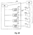
Fig. 2B is a schematic view of the environmental control system ofFig. 2A , showing the system in a second operating mode; and -
Fig. 3 is a flow chart of an exemplary embodiment of a method in accordance with this disclosure. - Reference will now be made to the drawings wherein like reference numerals identify similar structural features or aspects of the subject disclosure. For purposes of explanation and illustration, and not limitation, an illustrative view of an embodiment of an environmental control system in accordance with the disclosure is shown in
Fig. 2A and is designated generally byreference character 200. Other embodiments and/or aspects of this disclosure are shown inFigs. 1 and2B . The systems and methods described herein can be used to improve the efficiency of environmental control systems. -
Fig. 1 schematically illustrates agas turbine engine 20. Thegas turbine engine 20 is disclosed herein as a two-spool turbofan that generally incorporates afan section 22, acompressor section 24, acombustor section 26 and a turbine section 28. Alternative engines might include an augmentor section (not shown) among other systems or features. Thefan section 22 drives air along a bypass flow path B in a bypass duct defined within anacelle 15, while thecompressor section 24 drives air along a core flow path C for compression and communication into thecombustor section 26 then expansion through the turbine section 28. Although depicted as a two-spool turbofan gas turbine engine in the disclosed non-limiting embodiment, it should be understood that the concepts described herein are not limited to use with two-spool turbofans as the teachings may be applied to other types of turbine engines including three-spool architectures. - Referring to
Figs. 2A and2B , an environmental control system (ECS) 200 for a multi- engine aircraft includes acontroller 201 configured to switch the ECS 200 between a plurality of operating modes. Thecontroller 201 can include any suitable hardware and/or software configured to change modes of the ECS 200 as is understood by those having ordinary skill in the art. - The plurality of operating modes includes a first operating mode (e.g., as shown in
Fig. 2A ) such that the ECS 200 is configured to receive bleed air from eachengine engine engines engines Figs. 2A and2B as being in the order of 209d, 209a, 209b, 209c. The plurality of operating modes also includes a second operating mode (e.g., as shown inFig. 2B ) such that theECS 200 is configured to receive bleed air from at least oneengine engine 209a can provide higher pressure bleed whereasengine 209c can provide no bleed air or reduced pressure bleed air). - Referring to
Fig. 2B , thecontroller 201 can be operatively connected to athrust controller 300. Thethrust controller 300 can be any suitable controller (e.g., a throttle mechanism, a full authority digital engine control (FADEC)) that can connect to eachengine engine - The
controller 201 can command thethrust controller 300 to cause engine thrust to increase in at least one engine (e.g.,engines ECS 200 is in the second operating mode. Similarly, thecontroller 201 can command thethrust controller 300 to reduce thrust from at least one other engine (e.g.,engines ECS 200 is in the second operating mode. Thus, to prevent increasing airspeed, and/or to prevent over pressurization, and/or to prevent changing flight configuration (with respect to lift, thrust, and speed), thrust must be reduced in an equal amount (e.g., inengines engines - As shown, the
controller 201 can command thethrust controller 300 to increase or reduce thrust symmetrically to prevent asymmetric thrust induced yaw. For example,engines engines controller 201 can communicate with a flight control system (not shown) to trim the rudder automatically to the required amount. It is contemplated that even in the rudder trimmed scenario, e.g., for a two engine aircraft, that the overall efficiency of the system will be improved because of how relatively little time in that scenario would be required when compared to the total operating time of the aircraft. - The
system 200 can further include a plurality of ECS packs 203, 205, eachECS pack engine suitable fluid circuit 207. EachECS pack ECS pack 203 that is operative to change from a first cooling mode in the first operational mode (e.g., as shown inFig. 2A ) to a second cooling mode in the second operational mode (e.g., as shown inFig. 2B ). - The second cooling mode can allow each mode changing
ECS pack 203 to operate with higher bleed air pressure than the first cooling mode such that an increase in thrust (and thus bleed air pressure) from an engine (e.g.,engines ECS pack 203 can draw bleed air from the high pressure compressor (either independently of a low pressure compressor bleed or in conjunction therewith). In conjunction therewith, each single mode ECS pack can shut off bleed flow from their respective engine to maintain suitable total pressure within theECS 200. - As shown, the
controller 201 can be operatively connected to the mode changing ECS packs 203 to communicate with the ECS packs 203 and/or to cause the ECS packs 203 to change between cooling modes. While asingle controller 201 is shown separate from the ECS packs 203, it is contemplated that thecontroller 201 can be an internal component of each mode changingECS pack 203 and/or thatmultiple controllers 201 can exist (e.g., acontroller 201 for each ECS pack 203). Thecontroller 201 can change the operating mode of theECS 200 by virtue of changing the cooling mode of one or more of the ECS packs 203 as is understood by those skilled in the art (e.g., opening a high pressure bleed valve) and/or by modifying engine thrust of suitable engines (e.g.,engines - As shown, the
ECS 200 for a four engine aircraft can be arranged such that the plurality of ECS packs 203, 205 can include twomode changing packs 203 connected tosymmetric engines - Each
ECS pack - In certain embodiments, the mode change ECS packs 203 can be configured to switch from the first cooling mode to the second cooling mode automatically based on at least one engine operating parameter. The at least one engine operating parameter can include bleed air pressure, engine speed, or any other suitable parameter.
- In certain embodiments, the mode change ECS packs 203 can be configured to switch from the first cooling mode to the second cooling mode automatically based on at least one environmental condition. For example, the at least one environmental condition can include atmospheric air temperature, atmospheric air pressure, atmospheric air density, or a predetermined altitude.
- Referring additionally to
Fig. 3 , amethod 301 for supplying pressurized air to an aircraft includes bleeding bleed air (e.g., block 303) from a portion of a turbomachine (e.g.,engine engine engine engine - Increasing the thrust output can include increasing the thrust output of a first turbomachine (e.g.,
engine 209a) and a second turbomachine (e.g.,engine 209b) that is symmetrically located relative to the first turbomachine (e.g.,engine 209a). The thrust output of the first and second turbomachines can be increased by about an equal amount to prevent asymmetric thrust induced yaw. It is also contemplated that an uneven increase in output thrust can be created and the yaw induced thereby offset by other suitable aircraft systems (e.g., the rudder input). - The method can further include reducing a thrust output of a third turbomachine (e.g.,
engine 209c) of the aircraft to maintain a constant total thrust. Reducing the thrust output can include reducing the thrust output of a fourth turbomachine (e.g.,engine 209d) that is symmetrically located relative to the third turbomachine (e.g.,engine 209c) to prevent asymmetric thrust induced yaw. - The method can further include switching modes of an environmental control system (ECS) 200 from a first operating mode as described above, to a second operating mode as described above. Switching modes of the
ECS 200 can include switching at least one mode changingECS pack 203 from a first cooling mode to a second cooling mode. Switching modes of theECS 200 can include maintaining a constant cooling mode in at least oneECS pack 205. Alternatively or additionally, switching modes can include shutting off bleed air from the engines connected to the single mode ECS packs 205 using the ECS packs 205 or any other suitable mechanism/valve associated therewith. - The above systems and methods allow for bleed location to be selected at lower pressure portions of each engine which increases the efficiency of the
ECS system 200 because unnecessary pressure is not being used all the time. In the small percentage of flight operations when a higher pressure is needed to be produced due to environmental conditions, such as on a hot day at high altitudes, one or more of the engines can increase thrust to provide the proper amount of bleed pressure. - The methods and systems of the present disclosure, as described above and shown in the drawings, provide for improved environmental control systems with superior properties including improved efficiency. While the apparatus and methods of the subject disclosure have been shown and described with reference to embodiments, those skilled in the art will readily appreciate that changes and/or modifications may be made thereto without departing from the scope of the subject disclosure.
- The following clauses set out features of the present disclosure which may or may not presently be claimed but which may serve as basis for future amendments and/or a divisional application.
- 1. An environmental control system (ECS) for a multi-engine aircraft, comprising:
- a controller configured to switch the ECS between a plurality of operating modes, the plurality of operating modes comprising:
- a first operating mode configured to receive bleed air from each engine of the aircraft in a first environmental condition, wherein the pressure of the bleed air is about equal from each engine; and
- a second operating mode configured to receive bleed air from at least one engine of the aircraft in a second environmental condition, wherein the pressure of the bleed air is different between at least two engines.
- a controller configured to switch the ECS between a plurality of operating modes, the plurality of operating modes comprising:
- 2. The system of
clause 1, wherein the controller is operatively connected to a thrust controller to cause engine thrust to increase in at least one engine and to reduce thrust from at least one other engine to maintain a constant total thrust when the ECS is in the second operating mode. - 3. The system of
clause 1, wherein bleed air from at least one engine is shut off in the second environmental condition. - 4. The system of
clause 2, wherein the controller is operatively connected to the thrust controller to increase or reduce thrust symmetrically to prevent asymmetric thrust induced yaw. - 5. The system of
clause 1, further comprising a plurality of ECS packs, each ECS pack connected to a respective one of the engines, wherein at least one of the plurality of ECS packs is a mode changing ECS pack that is operative to change from a first cooling mode in the first operational mode to a second cooling mode in the second operational mode, wherein the second cooling mode allows the ECS pack to operate with higher bleed air pressure than the first cooling mode. - 6. The system of clause 5, wherein each ECS pack includes a heat exchanger operative to cool the bleed air.
- 7. The system of clause 5, wherein the plurality of ECS packs includes two mode changing packs connected to symmetric engines, and wherein two single mode ECS packs are connected to the remaining engines.
- 8. The system of clause 7, wherein the single mode ECS packs are configured to shut off bleed air from their respective engines when the ECS is in the second operating mode.
- 9. An aircraft, comprising:
- a plurality of engines; and
- an environmental control system (ECS), comprising:
- a controller configured to switch the ECS between a plurality of operating modes, the plurality of operating modes comprising:
- a first operating mode configured to receive bleed air from each engine of the aircraft in a first environmental condition, wherein the pressure of the bleed air is about equal from each engine; and
- a second operating mode configured to receive bleed air from at least one engine of the aircraft in a second environmental condition, wherein the pressure of the bleed air is different between at least two engines.
- 10. The aircraft of clause 9, wherein the controller is operatively connected to a thrust controller to cause engine thrust to increase in at least one engine and to reduce thrust from at least one other engine to maintain a constant total thrust when the ECS is in the second operating mode.
- 11. The aircraft of clause 9, wherein bleed air from at least one engine is shut off in the second environmental condition.
- 12. A method for supplying pressurized air to an aircraft, comprising: bleeding bleed air from a portion of a turbomachine of the aircraft; and
increasing a thrust output of the turbomachine to increase a pressure of the bleed air in a predetermined environmental condition. - 13. The method of clause 12, wherein the turbomachine is a first turbomachine, further comprising reducing a thrust output of a second turbomachine of the aircraft to maintain a constant total thrust.
- 14. The method of clause 12, wherein increasing the thrust output includes increasing the thrust output of a first turbomachine and a second turbomachine that is symmetrically located relative to the first turbomachine.
- 15. The method of clause 14, wherein the thrust output of the first and second turbomachines is increased by about an equal amount to prevent asymmetric thrust induced yaw.
- 16. The method of clause 14, further comprising reducing a thrust output of a third turbomachine of the aircraft to maintain a constant total thrust.
- 17. The method of clause 16, wherein reducing the thrust output further includes reducing the thrust output of a fourth turbomachine that is symmetrically located relative to the third turbomachine to prevent asymmetric thrust induced yaw.
- 18. The method of clause 12, further comprising switching modes of an environmental control system (ECS) from a first operating mode configured to receive bleed air from each engine of the aircraft in a first environmental condition, wherein the pressure of the bleed air is about equal from each engine, to a second operating mode configured to receive bleed air from at least one engine of the aircraft in a second environmental condition, wherein the pressure of the bleed air is different between at least two engines.
- 19. The method of clause 18, wherein switching modes of the ECS includes switching at least one ECS pack from a first cooling mode to a second cooling mode.
- 20. The method of clause 19, wherein switching modes of the ECS includes maintaining a constant cooling mode in at least one ECS pack.
Claims (15)
- An environmental control system (ECS) (200) for a multi-engine aircraft, comprising:a controller (201) configured to switch the ECS between a plurality of operating modes, the plurality of operating modes comprising:a first operating mode configured to receive bleed air from each engine (209a, 209b, 209c, 209d) of the aircraft in a first environmental condition, wherein the pressure of the bleed air is about equal from each engine; anda second operating mode configured to receive bleed air from at least one engine of the aircraft in a second environmental condition, wherein the pressure of the bleed air is different between at least two engines.
- The system (200) of claim 1, wherein the controller (201) is operatively connected to a thrust controller (300) to cause engine thrust to increase in at least one engine (209a, 209b, 209c, 209d) and to reduce thrust from at least one other engine to maintain a constant total thrust when the ECS is in the second operating mode.
- The system (200) of claim 1 or 2, wherein bleed air from at least one engine (209a, 209b, 209c, 209d) is shut off in the second environmental condition.
- The system (200) of claim 2, wherein the controller (201) is operatively connected to the thrust controller (300) to increase or reduce thrust symmetrically to prevent asymmetric thrust induced yaw.
- The system (200) of any preceding claim, further comprising a plurality of ECS packs (203, 205), each ECS pack connected to a respective one of the engines (209a, 209b, 209c, 209d), wherein at least one of the plurality of ECS packs is a mode changing ECS pack (203) that is operative to change from a first cooling mode in the first operational mode to a second cooling mode in the second operational mode, wherein the second cooling mode allows the ECS pack to operate with higher bleed air pressure than the first cooling mode.
- The system (200) of claim 5, wherein each ECS pack (203, 205) includes a heat exchanger operative to cool the bleed air.
- The system (200) of claim 5 or 6, wherein the plurality of ECS packs (203, 205) includes two mode changing packs (203) connected to symmetric engines (209a, 209b), and wherein two single mode ECS packs (205) are connected to the remaining engines (209c, 209d); and
preferably wherein the single mode ECS packs are configured to shut off bleed air from their respective engines when the ECS is in the second operating mode. - An aircraft, comprising:a plurality of engines (209a, 209b, 209c, 209d); andan environmental control system (ECS) (200) according to any preceding claim.
- A method (301) for supplying pressurized air to an aircraft, comprising:bleeding (303) bleed air from a portion of a turbomachine of the aircraft; andincreasing (305) a thrust output of the turbomachine to increase a pressure of the bleed air in a predetermined environmental condition.
- The method (301) of claim 9, wherein the turbomachine is a first turbomachine (209a, 209b), further comprising reducing a thrust output of a second turbomachine (209c, 209d) of the aircraft to maintain a constant total thrust.
- The method (301) of claim 9 or 10, wherein increasing the thrust output includes increasing the thrust output of a first turbomachine (209a) and a second turbomachine (209b) that is symmetrically located relative to the first turbomachine.
- The method (301) of claim 11, wherein the thrust output of the first (209a) and second turbomachines (209b) is increased by about an equal amount to prevent asymmetric thrust induced yaw.
- The method (301) of claim 11 or 12, further comprising reducing a thrust output of a third turbomachine (209c) of the aircraft to maintain a constant total thrust; and
preferably wherein reducing the thrust output further includes reducing the thrust output of a fourth turbomachine (209d) that is symmetrically located relative to the third turbomachine to prevent asymmetric thrust induced yaw. - The method (301) of any of claims 9 to 13, further comprising switching modes of an environmental control system (ECS) (200) from a first operating mode configured to receive bleed air from each engine (209a, 209b, 209c, 209d) of the aircraft in a first environmental condition, wherein the pressure of the bleed air is about equal from each engine, to a second operating mode configured to receive bleed air from at least one engine of the aircraft in a second environmental condition, wherein the pressure of the bleed air is different between at least two engines.
- The method (301) of claim 14, wherein switching modes of the ECS includes switching at least one ECS pack (203, 205) from a first cooling mode to a second cooling mode; and
preferably wherein switching modes of the ECS includes maintaining a constant cooling mode in at least one ECS pack.
Applications Claiming Priority (1)
| Application Number | Priority Date | Filing Date | Title |
|---|---|---|---|
| US201562159421P | 2015-05-11 | 2015-05-11 |
Publications (2)
| Publication Number | Publication Date |
|---|---|
| EP3095703A1 true EP3095703A1 (en) | 2016-11-23 |
| EP3095703B1 EP3095703B1 (en) | 2019-07-03 |
Family
ID=55963267
Family Applications (1)
| Application Number | Title | Priority Date | Filing Date |
|---|---|---|---|
| EP16169218.1A Active EP3095703B1 (en) | 2015-05-11 | 2016-05-11 | Environmental cooling systems for aircraft |
Country Status (2)
| Country | Link |
|---|---|
| US (2) | US10494106B2 (en) |
| EP (1) | EP3095703B1 (en) |
Cited By (5)
| Publication number | Priority date | Publication date | Assignee | Title |
|---|---|---|---|---|
| EP3715248A1 (en) * | 2019-03-27 | 2020-09-30 | Pratt & Whitney Canada Corp. | Air system switching system to allow aero-engines to operate in standby mode |
| US11274611B2 (en) | 2019-05-31 | 2022-03-15 | Pratt & Whitney Canada Corp. | Control logic for gas turbine engine fuel economy |
| US11326525B2 (en) | 2019-10-11 | 2022-05-10 | Pratt & Whitney Canada Corp. | Aircraft bleed air systems and methods |
| US11391219B2 (en) | 2019-04-18 | 2022-07-19 | Pratt & Whitney Canada Corp. | Health monitor for air switching system |
| US11859563B2 (en) | 2019-05-31 | 2024-01-02 | Pratt & Whitney Canada Corp. | Air system of multi-engine aircraft |
Families Citing this family (1)
| Publication number | Priority date | Publication date | Assignee | Title |
|---|---|---|---|---|
| CN112591104B (en) * | 2020-12-04 | 2026-04-03 | 中航通飞华南飞机工业有限公司 | A four-engine aircraft interactive bleed air system and its usage method |
Citations (5)
| Publication number | Priority date | Publication date | Assignee | Title |
|---|---|---|---|---|
| GB1083573A (en) * | 1963-03-12 | 1967-09-13 | Bristol Siddeley Engines Ltd | Air conditioning apparatus for aircraft |
| US4735056A (en) * | 1986-06-30 | 1988-04-05 | United Technologies Corporation | Pressure regulating valve controller |
| US20060174628A1 (en) * | 2005-02-09 | 2006-08-10 | Honeywell International Inc. | Method and system for balancing bleed flows from gas turbine engines |
| US20090117840A1 (en) * | 2005-08-08 | 2009-05-07 | Liebherr-Aerospace Lindenberg Gmbh | Method of operating an aircraft system |
| US20130151039A1 (en) * | 2010-08-25 | 2013-06-13 | Turbomeca | Method for optimizing the overall energy efficiency of an aircraft, and main power package for implementing same |
Family Cites Families (10)
| Publication number | Priority date | Publication date | Assignee | Title |
|---|---|---|---|---|
| US5114103A (en) * | 1990-08-27 | 1992-05-19 | General Electric Company | Aircraft engine electrically powered boundary layer bleed system |
| US5967461A (en) * | 1997-07-02 | 1999-10-19 | Mcdonnell Douglas Corp. | High efficiency environmental control systems and methods |
| US7210653B2 (en) * | 2002-10-22 | 2007-05-01 | The Boeing Company | Electric-based secondary power system architectures for aircraft |
| US7102380B2 (en) * | 2004-07-07 | 2006-09-05 | Kao Richard F C | High speed integrated circuit |
| US9810158B2 (en) * | 2014-04-01 | 2017-11-07 | The Boeing Company | Bleed air systems for use with aircraft and related methods |
| US10054051B2 (en) * | 2014-04-01 | 2018-08-21 | The Boeing Company | Bleed air systems for use with aircraft and related methods |
| US9657648B2 (en) * | 2014-11-25 | 2017-05-23 | Hamilton Sundstrand Corporation | Environmental air conditioning system |
| CA2979615C (en) * | 2015-03-16 | 2023-09-26 | Bombardier Inc. | Synchronization of aircraft engines |
| GB201513952D0 (en) * | 2015-08-07 | 2015-09-23 | Rolls Royce Plc | Aircraft pneumatic system |
| US9896216B2 (en) * | 2016-06-01 | 2018-02-20 | Honeywell Limited | ECO mode ECS logic |
-
2016
- 2016-05-11 US US15/151,938 patent/US10494106B2/en active Active
- 2016-05-11 EP EP16169218.1A patent/EP3095703B1/en active Active
-
2019
- 2019-11-06 US US16/675,585 patent/US10669031B2/en active Active
Patent Citations (5)
| Publication number | Priority date | Publication date | Assignee | Title |
|---|---|---|---|---|
| GB1083573A (en) * | 1963-03-12 | 1967-09-13 | Bristol Siddeley Engines Ltd | Air conditioning apparatus for aircraft |
| US4735056A (en) * | 1986-06-30 | 1988-04-05 | United Technologies Corporation | Pressure regulating valve controller |
| US20060174628A1 (en) * | 2005-02-09 | 2006-08-10 | Honeywell International Inc. | Method and system for balancing bleed flows from gas turbine engines |
| US20090117840A1 (en) * | 2005-08-08 | 2009-05-07 | Liebherr-Aerospace Lindenberg Gmbh | Method of operating an aircraft system |
| US20130151039A1 (en) * | 2010-08-25 | 2013-06-13 | Turbomeca | Method for optimizing the overall energy efficiency of an aircraft, and main power package for implementing same |
Cited By (8)
| Publication number | Priority date | Publication date | Assignee | Title |
|---|---|---|---|---|
| EP3715248A1 (en) * | 2019-03-27 | 2020-09-30 | Pratt & Whitney Canada Corp. | Air system switching system to allow aero-engines to operate in standby mode |
| US11274599B2 (en) | 2019-03-27 | 2022-03-15 | Pratt & Whitney Canada Corp. | Air system switching system to allow aero-engines to operate in standby mode |
| US11732643B2 (en) | 2019-03-27 | 2023-08-22 | Pratt & Whitney Canada Corp | Air system switching system to allow aero-engines to operate in standby mode |
| US11391219B2 (en) | 2019-04-18 | 2022-07-19 | Pratt & Whitney Canada Corp. | Health monitor for air switching system |
| US11274611B2 (en) | 2019-05-31 | 2022-03-15 | Pratt & Whitney Canada Corp. | Control logic for gas turbine engine fuel economy |
| US11725595B2 (en) | 2019-05-31 | 2023-08-15 | Pratt & Whitney Canada Corp. | Control logic for gas turbine engine fuel economy |
| US11859563B2 (en) | 2019-05-31 | 2024-01-02 | Pratt & Whitney Canada Corp. | Air system of multi-engine aircraft |
| US11326525B2 (en) | 2019-10-11 | 2022-05-10 | Pratt & Whitney Canada Corp. | Aircraft bleed air systems and methods |
Also Published As
| Publication number | Publication date |
|---|---|
| US10494106B2 (en) | 2019-12-03 |
| EP3095703B1 (en) | 2019-07-03 |
| US20200070985A1 (en) | 2020-03-05 |
| US10669031B2 (en) | 2020-06-02 |
| US20160332737A1 (en) | 2016-11-17 |
Similar Documents
| Publication | Publication Date | Title |
|---|---|---|
| US10669031B2 (en) | Environmental cooling systems for aircraft | |
| US11384690B2 (en) | System and method of reducing post-shutdown engine temperatures | |
| US9239005B2 (en) | Cooling system for engine and aircraft air | |
| US20260117709A1 (en) | Controlling a compressor of a turbine engine | |
| CA2905233C (en) | Intelligent integrated control system and method | |
| US9260974B2 (en) | System and method for active clearance control | |
| EP2871349B1 (en) | Method of operating a pneumatic system for an aircraft | |
| EP3092388B1 (en) | Cross-stream heat exchanger | |
| CA2855867C (en) | Bleed air systems for use with aircrafts and related methods | |
| US20150354464A1 (en) | Method and apparatus for controlling a compressor of a gas turbine engine | |
| US20150107261A1 (en) | Pneumatic system for an aircraft | |
| EP3667044B1 (en) | System and method for selectively modulating the flow of bleed air used for high pressure turbine stage cooling in a power turbine engine | |
| CN107002560A (en) | Cooling equipment for turbines supplied by discharge circuit | |
| EP3321490B1 (en) | Turbo-generator based bleed air system | |
| CN107083999A (en) | Method and system for the modulation turbine cooling with engine changes in health | |
| US20230220815A1 (en) | Three-stream gas turbine engine control | |
| EP3744636B1 (en) | Air system of multi-engine aircraft | |
| EP3181870B1 (en) | Gas turbine engine with a modulated bleed valve and corresponding method of varying a bleed airflow | |
| US20240159157A1 (en) | Gas turbine engine bleed air flow control | |
| EP3112268A1 (en) | Aircraft environmental control system selectively powered by three bleed ports |
Legal Events
| Date | Code | Title | Description |
|---|---|---|---|
| PUAI | Public reference made under article 153(3) epc to a published international application that has entered the european phase |
Free format text: ORIGINAL CODE: 0009012 |
|
| AK | Designated contracting states |
Kind code of ref document: A1 Designated state(s): AL AT BE BG CH CY CZ DE DK EE ES FI FR GB GR HR HU IE IS IT LI LT LU LV MC MK MT NL NO PL PT RO RS SE SI SK SM TR |
|
| AX | Request for extension of the european patent |
Extension state: BA ME |
|
| STAA | Information on the status of an ep patent application or granted ep patent |
Free format text: STATUS: REQUEST FOR EXAMINATION WAS MADE |
|
| 17P | Request for examination filed |
Effective date: 20170523 |
|
| RBV | Designated contracting states (corrected) |
Designated state(s): AL AT BE BG CH CY CZ DE DK EE ES FI FR GB GR HR HU IE IS IT LI LT LU LV MC MK MT NL NO PL PT RO RS SE SI SK SM TR |
|
| GRAP | Despatch of communication of intention to grant a patent |
Free format text: ORIGINAL CODE: EPIDOSNIGR1 |
|
| STAA | Information on the status of an ep patent application or granted ep patent |
Free format text: STATUS: GRANT OF PATENT IS INTENDED |
|
| INTG | Intention to grant announced |
Effective date: 20190109 |
|
| GRAS | Grant fee paid |
Free format text: ORIGINAL CODE: EPIDOSNIGR3 |
|
| GRAA | (expected) grant |
Free format text: ORIGINAL CODE: 0009210 |
|
| STAA | Information on the status of an ep patent application or granted ep patent |
Free format text: STATUS: THE PATENT HAS BEEN GRANTED |
|
| AK | Designated contracting states |
Kind code of ref document: B1 Designated state(s): AL AT BE BG CH CY CZ DE DK EE ES FI FR GB GR HR HU IE IS IT LI LT LU LV MC MK MT NL NO PL PT RO RS SE SI SK SM TR |
|
| REG | Reference to a national code |
Ref country code: GB Ref legal event code: FG4D |
|
| REG | Reference to a national code |
Ref country code: CH Ref legal event code: EP Ref country code: AT Ref legal event code: REF Ref document number: 1150691 Country of ref document: AT Kind code of ref document: T Effective date: 20190715 |
|
| REG | Reference to a national code |
Ref country code: IE Ref legal event code: FG4D |
|
| REG | Reference to a national code |
Ref country code: DE Ref legal event code: R096 Ref document number: 602016016150 Country of ref document: DE |
|
| REG | Reference to a national code |
Ref country code: NL Ref legal event code: MP Effective date: 20190703 |
|
| REG | Reference to a national code |
Ref country code: LT Ref legal event code: MG4D |
|
| REG | Reference to a national code |
Ref country code: AT Ref legal event code: MK05 Ref document number: 1150691 Country of ref document: AT Kind code of ref document: T Effective date: 20190703 |
|
| PG25 | Lapsed in a contracting state [announced via postgrant information from national office to epo] |
Ref country code: BG Free format text: LAPSE BECAUSE OF FAILURE TO SUBMIT A TRANSLATION OF THE DESCRIPTION OR TO PAY THE FEE WITHIN THE PRESCRIBED TIME-LIMIT Effective date: 20191003 Ref country code: NO Free format text: LAPSE BECAUSE OF FAILURE TO SUBMIT A TRANSLATION OF THE DESCRIPTION OR TO PAY THE FEE WITHIN THE PRESCRIBED TIME-LIMIT Effective date: 20191003 Ref country code: SE Free format text: LAPSE BECAUSE OF FAILURE TO SUBMIT A TRANSLATION OF THE DESCRIPTION OR TO PAY THE FEE WITHIN THE PRESCRIBED TIME-LIMIT Effective date: 20190703 Ref country code: AT Free format text: LAPSE BECAUSE OF FAILURE TO SUBMIT A TRANSLATION OF THE DESCRIPTION OR TO PAY THE FEE WITHIN THE PRESCRIBED TIME-LIMIT Effective date: 20190703 Ref country code: HR Free format text: LAPSE BECAUSE OF FAILURE TO SUBMIT A TRANSLATION OF THE DESCRIPTION OR TO PAY THE FEE WITHIN THE PRESCRIBED TIME-LIMIT Effective date: 20190703 Ref country code: FI Free format text: LAPSE BECAUSE OF FAILURE TO SUBMIT A TRANSLATION OF THE DESCRIPTION OR TO PAY THE FEE WITHIN THE PRESCRIBED TIME-LIMIT Effective date: 20190703 Ref country code: PT Free format text: LAPSE BECAUSE OF FAILURE TO SUBMIT A TRANSLATION OF THE DESCRIPTION OR TO PAY THE FEE WITHIN THE PRESCRIBED TIME-LIMIT Effective date: 20191104 Ref country code: NL Free format text: LAPSE BECAUSE OF FAILURE TO SUBMIT A TRANSLATION OF THE DESCRIPTION OR TO PAY THE FEE WITHIN THE PRESCRIBED TIME-LIMIT Effective date: 20190703 Ref country code: CZ Free format text: LAPSE BECAUSE OF FAILURE TO SUBMIT A TRANSLATION OF THE DESCRIPTION OR TO PAY THE FEE WITHIN THE PRESCRIBED TIME-LIMIT Effective date: 20190703 Ref country code: LT Free format text: LAPSE BECAUSE OF FAILURE TO SUBMIT A TRANSLATION OF THE DESCRIPTION OR TO PAY THE FEE WITHIN THE PRESCRIBED TIME-LIMIT Effective date: 20190703 |
|
| PG25 | Lapsed in a contracting state [announced via postgrant information from national office to epo] |
Ref country code: RS Free format text: LAPSE BECAUSE OF FAILURE TO SUBMIT A TRANSLATION OF THE DESCRIPTION OR TO PAY THE FEE WITHIN THE PRESCRIBED TIME-LIMIT Effective date: 20190703 Ref country code: ES Free format text: LAPSE BECAUSE OF FAILURE TO SUBMIT A TRANSLATION OF THE DESCRIPTION OR TO PAY THE FEE WITHIN THE PRESCRIBED TIME-LIMIT Effective date: 20190703 Ref country code: GR Free format text: LAPSE BECAUSE OF FAILURE TO SUBMIT A TRANSLATION OF THE DESCRIPTION OR TO PAY THE FEE WITHIN THE PRESCRIBED TIME-LIMIT Effective date: 20191004 Ref country code: AL Free format text: LAPSE BECAUSE OF FAILURE TO SUBMIT A TRANSLATION OF THE DESCRIPTION OR TO PAY THE FEE WITHIN THE PRESCRIBED TIME-LIMIT Effective date: 20190703 Ref country code: LV Free format text: LAPSE BECAUSE OF FAILURE TO SUBMIT A TRANSLATION OF THE DESCRIPTION OR TO PAY THE FEE WITHIN THE PRESCRIBED TIME-LIMIT Effective date: 20190703 Ref country code: IS Free format text: LAPSE BECAUSE OF FAILURE TO SUBMIT A TRANSLATION OF THE DESCRIPTION OR TO PAY THE FEE WITHIN THE PRESCRIBED TIME-LIMIT Effective date: 20191103 |
|
| PG25 | Lapsed in a contracting state [announced via postgrant information from national office to epo] |
Ref country code: TR Free format text: LAPSE BECAUSE OF FAILURE TO SUBMIT A TRANSLATION OF THE DESCRIPTION OR TO PAY THE FEE WITHIN THE PRESCRIBED TIME-LIMIT Effective date: 20190703 |
|
| PG25 | Lapsed in a contracting state [announced via postgrant information from national office to epo] |
Ref country code: PL Free format text: LAPSE BECAUSE OF FAILURE TO SUBMIT A TRANSLATION OF THE DESCRIPTION OR TO PAY THE FEE WITHIN THE PRESCRIBED TIME-LIMIT Effective date: 20190703 Ref country code: RO Free format text: LAPSE BECAUSE OF FAILURE TO SUBMIT A TRANSLATION OF THE DESCRIPTION OR TO PAY THE FEE WITHIN THE PRESCRIBED TIME-LIMIT Effective date: 20190703 Ref country code: DK Free format text: LAPSE BECAUSE OF FAILURE TO SUBMIT A TRANSLATION OF THE DESCRIPTION OR TO PAY THE FEE WITHIN THE PRESCRIBED TIME-LIMIT Effective date: 20190703 Ref country code: EE Free format text: LAPSE BECAUSE OF FAILURE TO SUBMIT A TRANSLATION OF THE DESCRIPTION OR TO PAY THE FEE WITHIN THE PRESCRIBED TIME-LIMIT Effective date: 20190703 Ref country code: IT Free format text: LAPSE BECAUSE OF FAILURE TO SUBMIT A TRANSLATION OF THE DESCRIPTION OR TO PAY THE FEE WITHIN THE PRESCRIBED TIME-LIMIT Effective date: 20190703 |
|
| PG25 | Lapsed in a contracting state [announced via postgrant information from national office to epo] |
Ref country code: SM Free format text: LAPSE BECAUSE OF FAILURE TO SUBMIT A TRANSLATION OF THE DESCRIPTION OR TO PAY THE FEE WITHIN THE PRESCRIBED TIME-LIMIT Effective date: 20190703 Ref country code: IS Free format text: LAPSE BECAUSE OF FAILURE TO SUBMIT A TRANSLATION OF THE DESCRIPTION OR TO PAY THE FEE WITHIN THE PRESCRIBED TIME-LIMIT Effective date: 20200224 Ref country code: SK Free format text: LAPSE BECAUSE OF FAILURE TO SUBMIT A TRANSLATION OF THE DESCRIPTION OR TO PAY THE FEE WITHIN THE PRESCRIBED TIME-LIMIT Effective date: 20190703 |
|
| REG | Reference to a national code |
Ref country code: DE Ref legal event code: R097 Ref document number: 602016016150 Country of ref document: DE |
|
| PLBE | No opposition filed within time limit |
Free format text: ORIGINAL CODE: 0009261 |
|
| STAA | Information on the status of an ep patent application or granted ep patent |
Free format text: STATUS: NO OPPOSITION FILED WITHIN TIME LIMIT |
|
| PG2D | Information on lapse in contracting state deleted |
Ref country code: IS |
|
| 26N | No opposition filed |
Effective date: 20200603 |
|
| PG25 | Lapsed in a contracting state [announced via postgrant information from national office to epo] |
Ref country code: SI Free format text: LAPSE BECAUSE OF FAILURE TO SUBMIT A TRANSLATION OF THE DESCRIPTION OR TO PAY THE FEE WITHIN THE PRESCRIBED TIME-LIMIT Effective date: 20190703 |
|
| PG25 | Lapsed in a contracting state [announced via postgrant information from national office to epo] |
Ref country code: CH Free format text: LAPSE BECAUSE OF NON-PAYMENT OF DUE FEES Effective date: 20200531 Ref country code: MC Free format text: LAPSE BECAUSE OF FAILURE TO SUBMIT A TRANSLATION OF THE DESCRIPTION OR TO PAY THE FEE WITHIN THE PRESCRIBED TIME-LIMIT Effective date: 20190703 Ref country code: LI Free format text: LAPSE BECAUSE OF NON-PAYMENT OF DUE FEES Effective date: 20200531 |
|
| REG | Reference to a national code |
Ref country code: BE Ref legal event code: MM Effective date: 20200531 |
|
| PG25 | Lapsed in a contracting state [announced via postgrant information from national office to epo] |
Ref country code: LU Free format text: LAPSE BECAUSE OF NON-PAYMENT OF DUE FEES Effective date: 20200511 |
|
| PG25 | Lapsed in a contracting state [announced via postgrant information from national office to epo] |
Ref country code: IE Free format text: LAPSE BECAUSE OF NON-PAYMENT OF DUE FEES Effective date: 20200511 |
|
| PG25 | Lapsed in a contracting state [announced via postgrant information from national office to epo] |
Ref country code: BE Free format text: LAPSE BECAUSE OF NON-PAYMENT OF DUE FEES Effective date: 20200531 |
|
| PG25 | Lapsed in a contracting state [announced via postgrant information from national office to epo] |
Ref country code: MT Free format text: LAPSE BECAUSE OF FAILURE TO SUBMIT A TRANSLATION OF THE DESCRIPTION OR TO PAY THE FEE WITHIN THE PRESCRIBED TIME-LIMIT Effective date: 20190703 Ref country code: CY Free format text: LAPSE BECAUSE OF FAILURE TO SUBMIT A TRANSLATION OF THE DESCRIPTION OR TO PAY THE FEE WITHIN THE PRESCRIBED TIME-LIMIT Effective date: 20190703 |
|
| PG25 | Lapsed in a contracting state [announced via postgrant information from national office to epo] |
Ref country code: MK Free format text: LAPSE BECAUSE OF FAILURE TO SUBMIT A TRANSLATION OF THE DESCRIPTION OR TO PAY THE FEE WITHIN THE PRESCRIBED TIME-LIMIT Effective date: 20190703 |
|
| REG | Reference to a national code |
Ref country code: DE Ref legal event code: R081 Ref document number: 602016016150 Country of ref document: DE Owner name: RAYTHEON TECHNOLOGIES CORPORATION (N.D.GES.D.S, US Free format text: FORMER OWNER: UNITED TECHNOLOGIES CORPORATION, FARMINGTON, CONN., US Ref country code: DE Ref legal event code: R081 Ref document number: 602016016150 Country of ref document: DE Owner name: RTX CORPORATION (N.D.GES.D. STAATES DELAWARE),, US Free format text: FORMER OWNER: UNITED TECHNOLOGIES CORPORATION, FARMINGTON, CONN., US |
|
| P01 | Opt-out of the competence of the unified patent court (upc) registered |
Effective date: 20230520 |
|
| PGFP | Annual fee paid to national office [announced via postgrant information from national office to epo] |
Ref country code: DE Payment date: 20250423 Year of fee payment: 10 |
|
| PGFP | Annual fee paid to national office [announced via postgrant information from national office to epo] |
Ref country code: GB Payment date: 20250423 Year of fee payment: 10 |
|
| PGFP | Annual fee paid to national office [announced via postgrant information from national office to epo] |
Ref country code: FR Payment date: 20250423 Year of fee payment: 10 |
|
| REG | Reference to a national code |
Ref country code: DE Ref legal event code: R081 Ref document number: 602016016150 Country of ref document: DE Owner name: RTX CORPORATION (N.D.GES.D. STAATES DELAWARE),, US Free format text: FORMER OWNER: RAYTHEON TECHNOLOGIES CORPORATION (N.D.GES.D.STAATES DELAWARE), ARLINGTON, VA, US |