EP3095690A2 - Aircraft floor panel - Google Patents
Aircraft floor panel Download PDFInfo
- Publication number
- EP3095690A2 EP3095690A2 EP16170476.2A EP16170476A EP3095690A2 EP 3095690 A2 EP3095690 A2 EP 3095690A2 EP 16170476 A EP16170476 A EP 16170476A EP 3095690 A2 EP3095690 A2 EP 3095690A2
- Authority
- EP
- European Patent Office
- Prior art keywords
- floor panel
- layer
- aircraft
- support
- support layer
- Prior art date
- Legal status (The legal status is an assumption and is not a legal conclusion. Google has not performed a legal analysis and makes no representation as to the accuracy of the status listed.)
- Granted
Links
Images




Classifications
-
- B—PERFORMING OPERATIONS; TRANSPORTING
- B64—AIRCRAFT; AVIATION; COSMONAUTICS
- B64C—AEROPLANES; HELICOPTERS
- B64C1/00—Fuselages; Constructional features common to fuselages, wings, stabilising surfaces or the like
- B64C1/18—Floors
-
- B—PERFORMING OPERATIONS; TRANSPORTING
- B64—AIRCRAFT; AVIATION; COSMONAUTICS
- B64C—AEROPLANES; HELICOPTERS
- B64C1/00—Fuselages; Constructional features common to fuselages, wings, stabilising surfaces or the like
- B64C1/40—Sound or heat insulation, e.g. using insulation blankets
-
- B—PERFORMING OPERATIONS; TRANSPORTING
- B64—AIRCRAFT; AVIATION; COSMONAUTICS
- B64D—EQUIPMENT FOR FITTING IN OR TO AIRCRAFT; FLIGHT SUITS; PARACHUTES; ARRANGEMENT OR MOUNTING OF POWER PLANTS OR PROPULSION TRANSMISSIONS IN AIRCRAFT
- B64D13/00—Arrangements or adaptations of air-treatment apparatus for aircraft crew or passengers, or freight space
- B64D13/06—Arrangements or adaptations of air-treatment apparatus for aircraft crew or passengers, or freight space the air being conditioned
- B64D13/08—Arrangements or adaptations of air-treatment apparatus for aircraft crew or passengers, or freight space the air being conditioned the air being heated or cooled
-
- F—MECHANICAL ENGINEERING; LIGHTING; HEATING; WEAPONS; BLASTING
- F24—HEATING; RANGES; VENTILATING
- F24D—DOMESTIC- OR SPACE-HEATING SYSTEMS, e.g. CENTRAL HEATING SYSTEMS; DOMESTIC HOT-WATER SUPPLY SYSTEMS; ELEMENTS OR COMPONENTS THEREFOR
- F24D13/00—Electric heating systems
- F24D13/02—Electric heating systems solely using resistance heating, e.g. underfloor heating
- F24D13/022—Electric heating systems solely using resistance heating, e.g. underfloor heating resistances incorporated in construction elements
- F24D13/024—Electric heating systems solely using resistance heating, e.g. underfloor heating resistances incorporated in construction elements in walls, floors, ceilings
-
- B—PERFORMING OPERATIONS; TRANSPORTING
- B64—AIRCRAFT; AVIATION; COSMONAUTICS
- B64C—AEROPLANES; HELICOPTERS
- B64C1/00—Fuselages; Constructional features common to fuselages, wings, stabilising surfaces or the like
- B64C2001/0054—Fuselage structures substantially made from particular materials
- B64C2001/0072—Fuselage structures substantially made from particular materials from composite materials
-
- Y—GENERAL TAGGING OF NEW TECHNOLOGICAL DEVELOPMENTS; GENERAL TAGGING OF CROSS-SECTIONAL TECHNOLOGIES SPANNING OVER SEVERAL SECTIONS OF THE IPC; TECHNICAL SUBJECTS COVERED BY FORMER USPC CROSS-REFERENCE ART COLLECTIONS [XRACs] AND DIGESTS
- Y02—TECHNOLOGIES OR APPLICATIONS FOR MITIGATION OR ADAPTATION AGAINST CLIMATE CHANGE
- Y02B—CLIMATE CHANGE MITIGATION TECHNOLOGIES RELATED TO BUILDINGS, e.g. HOUSING, HOUSE APPLIANCES OR RELATED END-USER APPLICATIONS
- Y02B30/00—Energy efficient heating, ventilation or air conditioning [HVAC]
Definitions
- An aircraft commonly includes heated floor panels in order to maintain the cabin at a comfortable temperature.
- the floor panels are typically supported by an aircraft structure arranged, for example, in a grid-like pattern.
- the floor panels have structural integrity sufficient to support the weight of people and objects resting on the panels.
- a metal face sheet typically forms the top surface of the panel to protect the underlying layers from punctures from high heels, chips from dropped objects, scratches from dragged luggage and/or other floor-traffic related hazards.
- Some type of floor covering e.g., carpeting, tiling
- a heated floor panel can include a weight-supporting layer and a heat-generating layer.
- the floor panel can also include a heat-insulating layer to prevent heat from exiting the aircraft compartment.
- the heat-generating layer of the heated floor panels is typically placed just under the metal sheet or near the top surface of the floor. This makes the heating elements of the floor panels susceptible to damage (mechanical or due to fluid intrusion) during installation, maintenance or general use. The location of the heating element also makes localized repair to the metal face sheet or the top surface of the floor difficult.
- An aircraft heated floor panel includes a first support layer, a second support layer, and a heating layer located between the first support layer and the second support layer.
- An aircraft floor panel includes a floor panel body and a removal feature that provides a mechanism for the aircraft floor panel to be removed from an attached aircraft structure.
- FIG. 1 illustrates a cross sectional view of a heated floor panel.
- the uppermost surface of the panel shown in FIG. 1 is the top (external) surface of an installed floor panel.
- Heated floor panel 10 includes support layers 12 and 14, heating layer 16, adhesive layers 18 and 20, reinforcing layers 22 and 24 and floor covering 26.
- Support layers 12 and 14 are weight-bearing and/or insulating layers.
- Support layers 12 and 14 can be formed from a honeycomb material as shown in FIG. 1 .
- Suitable honeycomb materials include Nomex® (flame resistant aramid material) and Kevlar® (para-aramid synthetic fibers), both available from E. I. du Pont de Nemours and Company, Wilmington, DE.
- honeycomb layers are sandwiched between carbon fiber prepreg layers and/or fiberglass epoxy prepreg layers.
- Support layers 12 and 14 can also be formed of a foam or other core material. Suitable materials for foam layers include polyamide foams. Additional and different support layers 12 and 14 that provide sufficient stiffness, satisfy thickness limitations, and accommodate weight considerations can also be used.
- Support layers 12 and 14 can be of the same type (e.g., two honeycomb layers). Support layers 12 and 14 can contain the same material (e.g., identical honeycomb layers). Support layers 12 and 14 can also be of different types. In one embodiment, support layer 12 is a honeycomb layer and support layer 14 is a foam layer. In this embodiment, honeycomb layer 12 provides additional structural support above heating layer 16 while foam layer 14 provides additional insulating properties below heating layer 16.
- support layer 12 has thickness t 1 and support layer 14 has thickness t 2 .
- thickness t 1 and thickness t 2 are roughly equal. In cases where thickness t 1 and thickness t 2 are roughly equal, manufacturing heated floor panel 10 is easier to make flat due to the expansion and contraction of the various composite layers present in floor panel 10. In other embodiments one of thicknesses t 1 and t 2 is greater than the other depending on the structural and/or insulating requirements of a floor installation. Generally, the thicker support layer 12 or 14 will be no more than twice the thickness of the thinner support layer 12 or 14.
- Heating layer 16 can include an electrothermal heater.
- the electrothermal heater can be an electrically resistive element electrically isolated in a dielectric material.
- the element can be an etched foil type element or a wire and/or the element may be configured in a zig-zag type arrangement.
- the element can be isolated by encapsulation by disposing it between plies of an appropriate curable material such as thermoset plastic or any other dielectric or electrically non-conductive material.
- the plies may be made of a polyimide film, such as Kapton®, available from E. I. du Pont de Nemours and Company.
- heating layer 16 is inset a distance from the edges of floor panel 10 to protect the element of heating layer 16.
- heating layer 16 can be inset about 6.35 mm (0.25 inches) from the outer edges of panel 10 so that fluid from a spill or a cleaning solution does not run down the side of panel 10 and into heating layer 16. Insetting heating layer 16 can also reduce damage to heating layer 16 if one or more edges of heated floor panel 10 is damaged.
- Adhesive layers 18 and 20 are located between support layer 12 and heating layer 16 and heating layer 16 and support layer 14, respectively.
- adhesive layers 18 and 20 include a film adhesive (e.g., an epoxy).
- adhesive layers 18 and 20 include a prepreg (composite fibers impregnated with a matrix material such as an epoxy) having a high resin content. Film adhesive and resin-rich prepreg are used to increase the bond strength between heating layer 16 and support layers 12 and 14.
- Adhesive layers 18 and 20 should be capable of withstanding elevated curing temperatures so that, during the curing process, adhesive layers 18 and 20 will facilitate the bonding of the support layers 12 and 14 to heating layer 16.
- Adhesive layers 18 and 20 can incorporate a scrim if necessary or desired for better distribution of the adhesive.
- Reinforcing layers 22 and 24 provide additional structural reinforcement to heated floor panel 10.
- reinforcing layers 22 and 24 include multiple plies of a composite prepreg.
- Reinforcing layers 22 and 24 can include carbon fibers, fiberglass, Kevlar® or other reinforced polymer matrix materials.
- heated floor panel includes floor covering 26 as a top layer.
- Floor covering 26 can include composite prepreg plies with an outer metallic skin. In embodiments in which floor covering 26 is omitted, reinforcing layer 22 serves as the top layer of heated floor panel 10.
- Locating heating layer 16 between two support layers (12 and 14) offers increased protection to the heating element of heating layer 16.
- Support layer 12 protects heating layer 16 from mechanical damage during installation, maintenance and use and from fluid intrusion during operation (spills, etc.) and maintenance (e.g., cleaning). The structural loads encountered by heating layer 16 can be less severe. Moving heating layer 16 away from the top surface of heated floor panel 10 also allows for localized repair of support layer 12 and/or reinforcing layer 22 without damage to heating layer 16.
- FIGs. 2 through 10 illustrate different embodiments of floor panels and mechanisms that facilitate improved removal of floor panels from structures to which they are attached.
- Floor panels (heated or not) are often bolted and sealed to a mounting structure with caulk or other sealant. Due to the proximity of adjacent floor panels, the removal of individual floor panels is difficult and prone to cause damage to the floor panel being removed or surrounding panels.
- the present disclosure describes features for improving the removal of floor panels.
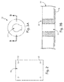
- FIG. 2 is a top view of floor panel 30.
- Floor panel 30 includes inserts 32, which are illustrated further in FIGs. 3A (top view) and 3B (cross section).
- FIG. 3A shows insert 32 with keyhole shaped opening 34.
- Insert 32 is positioned within a hole in floor panel 30 that extends from the top surface to the bottom surface.
- insert 32 includes a flange (flange 36) that is flush with the bottom surface of floor panel 30.
- Opening 34 is shaped to allow a tool to be inserted through insert 32 for panel removal.
- FIGs. 4A and 4B illustrate one example of such a tool.
- Tool 38 includes projection 40.
- Tool 38 with projection 40 is shaped to fit within opening 34 so that it can pass through insert 32.
- Tool 38 can then be rotated so that projection 40 interfaces with the bottom surface of panel 30.
- Tool 38 can then be used to pull panel 30 in an upwards direction with projection 40 applying force to panel 30 as shown in FIG. 5 .
- FIG. 6 is a top view of another embodiment of a floor panel.
- Floor panel 30A includes levers 42, which are illustrated further in FIGs. 7A (top view) and 7B (cross section).
- Levers 42 are integrated into floor panel 30A above the aircraft structure to which floor panels 30A are attached (structure 43).
- Levers 42 are attached to floor panel 30A with pin 44.
- end 46 of lever 42 is lifted, lever 42 rotates about pin 44 so that opposite end 47 of lever 42 exerts force on aircraft structure 43, pushing floor panel 30A away from aircraft structure 43.
- lever 42 can belong to insertable body 48 that is positioned within an opening in floor panel 30A.
- FIG. 8 is a cross section view of a floor panel similar to that illustrated in FIG. 2 .
- Floor panel 30B includes threaded insert 50.
- Threaded insert 50 includes threads 52 along its inner surface.
- a tool with a threaded end (not shown) can be inserted into insert 50 so that the threads of the tool engage with threads 52. The tool can then be used to pull up on floor panel 30B and remove it from the structure to which it is attached.
- a fastener can be threaded into the insert and the head of the fastener can be gripped and used to pull up on panel 30B.
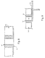
- FIG. 9 is a cross section view of a floor panel and a mounting structure.
- Floor panel 30C includes threaded insert 50 as described above.
- Fastener 54 is inserted within threaded insert 50.
- Fastener 54 is rotated with a tool (e.g., screwdriver) so that it engages with mounting structure 56. As fastener 54 rotates, it pushes mounting structure 56 and panel 30C away from one another, separating panel 30C from mounting structure 56.
- a tool e.g., screwdriver
- FIG. 10 is a cross section view of a floor panel having an edge with a recess.
- Floor panel 30D includes edge 58.
- Edge 58 contains recess 60 in which a tool can interface so that floor panel 30D can be removed from an attached aircraft structure. A tool (not shown) is received by recess 60 and an upward force exerted by the tool is used to pull up on floor panel 30D.
- Edge 58 can extend along the length of an entire side edge of floor panel 30D. Alternatively, edge 58 can extend along only a portion of the entire side edge of floor panel 30D. In some embodiments, edge 58 is formed by a plug of material attached to an opening in floor panel 30D.
- the plug can include a structural epoxy, fiberglass, machined metal or other material robust enough to withstand the forces necessary to remove floor panel 30D from the attached aircraft structure.
- areas where the tool is to be inserted to pry or lift edge 58 can be labeled on the top surface of floor panel 30D to prevent damage to floor panel 30D.
- the above described floor panels 30, 30A, 30B, 30C and 30D provide means for removing the floor panels from an attached aircraft structure while minimizing damage to the removed floor panels as well as those adjacent to the removed panel.
- An aircraft heated floor panel can include a first support layer, a second support layer, and a heating layer located between the first support layer and the second support layer.
- the aircraft heated floor panel of the preceding paragraph can optionally include, additionally and/or alternatively, any one or more of the following features, configurations and/or additional components:
- a further embodiment of the foregoing aircraft heated floor panel can include that the first and second support layers are weight-bearing layers.
- a further embodiment of any of the foregoing aircraft heated floor panels can include that the heating layer has a resistive heating element.
- a further embodiment of any of the foregoing aircraft heated floor panels can include that the resistive heating element is encapsulated in cured thennoset plastic plies.
- a further embodiment of any of the foregoing aircraft heated floor panels can include that the first and second support layers each have a honeycomb layer.
- a further embodiment of any of the foregoing aircraft heated floor panels can include that the honeycomb layers are sandwiched between fiber layers.
- a further embodiment of any of the foregoing aircraft heated floor panels can further include an external floor layer located adjacent the first support layer on a side opposite the heating layer.
- a further embodiment of any of the foregoing aircraft heated floor panels can include that the first support layer has a honeycomb layer and the second support layer has a foam layer.
- a further embodiment of any of the foregoing aircraft heated floor panels can further include a first adhesive layer located between the first support layer and the heating layer where the first adhesive layer has a film adhesive or a prepreg, and a second adhesive layer located between the second support layer and the heating layer where the second adhesive layer has a film adhesive or a prepreg.
- a further embodiment of any of the foregoing deicer boots can include that the non-woven electrospun fiber fabric sheet further comprises a non-electrospun elastomer.
- a further embodiment of any of the foregoing aircraft heated floor panels can include that the first support layer has a first thickness and the second support layer has a second thickness where a ratio of the first thickness to the second thickness is between about 1:2 and 2:1.
- a further embodiment of any of the foregoing aircraft heated floor panels can include that the first and second thicknesses are substantially equal.
- An aircraft floor panel can include a floor panel body and a removal feature that provides a mechanism for the aircraft floor panel to be removed from an attached aircraft structure.
Landscapes
- Engineering & Computer Science (AREA)
- Aviation & Aerospace Engineering (AREA)
- Mechanical Engineering (AREA)
- Health & Medical Sciences (AREA)
- Pulmonology (AREA)
- General Health & Medical Sciences (AREA)
- Physics & Mathematics (AREA)
- General Engineering & Computer Science (AREA)
- Combustion & Propulsion (AREA)
- Chemical & Material Sciences (AREA)
- Thermal Sciences (AREA)
- Floor Finish (AREA)
- Laminated Bodies (AREA)
Abstract
Description
- An aircraft commonly includes heated floor panels in order to maintain the cabin at a comfortable temperature. The floor panels are typically supported by an aircraft structure arranged, for example, in a grid-like pattern. The floor panels have structural integrity sufficient to support the weight of people and objects resting on the panels. A metal face sheet typically forms the top surface of the panel to protect the underlying layers from punctures from high heels, chips from dropped objects, scratches from dragged luggage and/or other floor-traffic related hazards. Some type of floor covering (e.g., carpeting, tiling) is typically placed over the panels for comfort and/or appearance. A heated floor panel can include a weight-supporting layer and a heat-generating layer. The floor panel can also include a heat-insulating layer to prevent heat from exiting the aircraft compartment.
- The heat-generating layer of the heated floor panels is typically placed just under the metal sheet or near the top surface of the floor. This makes the heating elements of the floor panels susceptible to damage (mechanical or due to fluid intrusion) during installation, maintenance or general use. The location of the heating element also makes localized repair to the metal face sheet or the top surface of the floor difficult.
- Additionally, aircraft floor panels are difficult to remove without damage to the panel. Floor panels are located very close together and no current tools or methods exist to extract floor panels without high risk of damage. Typical damage includes edge damage from prying with tools such as prybars and screwdrivers that can compromise the metal or composite panel structure. In the case of heated floor panels, damage can render the heating elements of the floor panel non-functional.
- An aircraft heated floor panel includes a first support layer, a second support layer, and a heating layer located between the first support layer and the second support layer.
- An aircraft floor panel includes a floor panel body and a removal feature that provides a mechanism for the aircraft floor panel to be removed from an attached aircraft structure.
-
-
FIG. 1 is a cross sectional view of a heated floor panel. -
FIG. 2 is a top view of a floor panel. -
FIG. 3A a detailed view of a section of the floor panel ofFIG. 2 . -
FIG. 3B is a cross section view of the floor panel ofFIG. 3A . -
FIGs. 4A and 4B are views of a tool configured to remove the floor panel ofFIG. 3A . -
FIG. 5 illustrates the tool engaged with the floor panel ofFIG. 3A . -
FIG. 6 is a top view of a floor panel. -
FIG. 7A a detailed view of a section of the floor panel ofFIG. 6 . -
FIG. 7B is a cross section view of the floor panel ofFIG. 7A . -
FIG. 8 is a cross section view of a floor panel. -
FIG. 9 is a cross section view of a floor panel and a mounting structure. -
FIG. 10 is a cross section view of a floor panel. -
FIG. 1 illustrates a cross sectional view of a heated floor panel. The uppermost surface of the panel shown inFIG. 1 is the top (external) surface of an installed floor panel. Heatedfloor panel 10 includessupport layers heating layer 16,adhesive layers layers -
Support layers Support layers FIG. 1 . Suitable honeycomb materials include Nomex® (flame resistant aramid material) and Kevlar® (para-aramid synthetic fibers), both available from E. I. du Pont de Nemours and Company, Wilmington, DE. In some embodiments, honeycomb layers are sandwiched between carbon fiber prepreg layers and/or fiberglass epoxy prepreg layers.Support layers different support layers -
Support layers Support layers Support layers support layer 12 is a honeycomb layer andsupport layer 14 is a foam layer. In this embodiment,honeycomb layer 12 provides additional structural support aboveheating layer 16 whilefoam layer 14 provides additional insulating properties belowheating layer 16. - As shown in
FIG. 1 ,support layer 12 has thickness t1 andsupport layer 14 has thickness t2. In some embodiments, thickness t1 and thickness t2 are roughly equal. In cases where thickness t1 and thickness t2 are roughly equal, manufacturing heatedfloor panel 10 is easier to make flat due to the expansion and contraction of the various composite layers present infloor panel 10. In other embodiments one of thicknesses t1 and t2 is greater than the other depending on the structural and/or insulating requirements of a floor installation. Generally, thethicker support layer thinner support layer -
Heating layer 16 can include an electrothermal heater. The electrothermal heater can be an electrically resistive element electrically isolated in a dielectric material. The element can be an etched foil type element or a wire and/or the element may be configured in a zig-zag type arrangement. The element can be isolated by encapsulation by disposing it between plies of an appropriate curable material such as thermoset plastic or any other dielectric or electrically non-conductive material. For example, the plies may be made of a polyimide film, such as Kapton®, available from E. I. du Pont de Nemours and Company. In some embodiments,heating layer 16 is inset a distance from the edges offloor panel 10 to protect the element ofheating layer 16. For example,heating layer 16 can be inset about 6.35 mm (0.25 inches) from the outer edges ofpanel 10 so that fluid from a spill or a cleaning solution does not run down the side ofpanel 10 and intoheating layer 16.Insetting heating layer 16 can also reduce damage toheating layer 16 if one or more edges ofheated floor panel 10 is damaged. - Adhesive layers 18 and 20 are located between
support layer 12 andheating layer 16 andheating layer 16 andsupport layer 14, respectively. In some embodiments,adhesive layers adhesive layers heating layer 16 and support layers 12 and 14. Adhesive layers 18 and 20 should be capable of withstanding elevated curing temperatures so that, during the curing process,adhesive layers heating layer 16. Adhesive layers 18 and 20 can incorporate a scrim if necessary or desired for better distribution of the adhesive. - Reinforcing
layers heated floor panel 10. In some embodiments, reinforcinglayers layers layer 22 serves as the top layer ofheated floor panel 10. - Locating
heating layer 16 between two support layers (12 and 14) offers increased protection to the heating element ofheating layer 16.Support layer 12 protectsheating layer 16 from mechanical damage during installation, maintenance and use and from fluid intrusion during operation (spills, etc.) and maintenance (e.g., cleaning). The structural loads encountered byheating layer 16 can be less severe. Movingheating layer 16 away from the top surface ofheated floor panel 10 also allows for localized repair ofsupport layer 12 and/or reinforcinglayer 22 without damage toheating layer 16. -
FIGs. 2 through 10 illustrate different embodiments of floor panels and mechanisms that facilitate improved removal of floor panels from structures to which they are attached. Floor panels (heated or not) are often bolted and sealed to a mounting structure with caulk or other sealant. Due to the proximity of adjacent floor panels, the removal of individual floor panels is difficult and prone to cause damage to the floor panel being removed or surrounding panels. The present disclosure describes features for improving the removal of floor panels. -
FIG. 2 is a top view offloor panel 30.Floor panel 30 includesinserts 32, which are illustrated further inFIGs. 3A (top view) and 3B (cross section).FIG. 3A showsinsert 32 with keyhole shapedopening 34.Insert 32 is positioned within a hole infloor panel 30 that extends from the top surface to the bottom surface. In some embodiments, insert 32 includes a flange (flange 36) that is flush with the bottom surface offloor panel 30.Opening 34 is shaped to allow a tool to be inserted throughinsert 32 for panel removal.FIGs. 4A and 4B illustrate one example of such a tool.Tool 38 includesprojection 40.Tool 38 withprojection 40 is shaped to fit within opening 34 so that it can pass throughinsert 32.Tool 38 can then be rotated so thatprojection 40 interfaces with the bottom surface ofpanel 30.Tool 38 can then be used to pullpanel 30 in an upwards direction withprojection 40 applying force topanel 30 as shown inFIG. 5 . -
FIG. 6 is a top view of another embodiment of a floor panel.Floor panel 30A includeslevers 42, which are illustrated further inFIGs. 7A (top view) and 7B (cross section).Levers 42 are integrated intofloor panel 30A above the aircraft structure to whichfloor panels 30A are attached (structure 43).Levers 42 are attached tofloor panel 30A withpin 44. When end 46 oflever 42 is lifted,lever 42 rotates aboutpin 44 so thatopposite end 47 oflever 42 exerts force onaircraft structure 43, pushingfloor panel 30A away fromaircraft structure 43. As shown inFIG. 7B ,lever 42 can belong toinsertable body 48 that is positioned within an opening infloor panel 30A. -
FIG. 8 is a cross section view of a floor panel similar to that illustrated inFIG. 2 .Floor panel 30B includes threadedinsert 50. Threadedinsert 50 includesthreads 52 along its inner surface. A tool with a threaded end (not shown) can be inserted intoinsert 50 so that the threads of the tool engage withthreads 52. The tool can then be used to pull up onfloor panel 30B and remove it from the structure to which it is attached. Alternatively, a fastener can be threaded into the insert and the head of the fastener can be gripped and used to pull up onpanel 30B. -
FIG. 9 is a cross section view of a floor panel and a mounting structure.Floor panel 30C includes threadedinsert 50 as described above.Fastener 54 is inserted within threadedinsert 50.Fastener 54 is rotated with a tool (e.g., screwdriver) so that it engages with mountingstructure 56. Asfastener 54 rotates, it pushes mountingstructure 56 andpanel 30C away from one another, separatingpanel 30C from mountingstructure 56. -
FIG. 10 is a cross section view of a floor panel having an edge with a recess.Floor panel 30D includesedge 58.Edge 58 containsrecess 60 in which a tool can interface so thatfloor panel 30D can be removed from an attached aircraft structure. A tool (not shown) is received byrecess 60 and an upward force exerted by the tool is used to pull up onfloor panel 30D.Edge 58 can extend along the length of an entire side edge offloor panel 30D. Alternatively, edge 58 can extend along only a portion of the entire side edge offloor panel 30D. In some embodiments,edge 58 is formed by a plug of material attached to an opening infloor panel 30D. The plug can include a structural epoxy, fiberglass, machined metal or other material robust enough to withstand the forces necessary to removefloor panel 30D from the attached aircraft structure. In some embodiments, areas where the tool is to be inserted to pry or liftedge 58 can be labeled on the top surface offloor panel 30D to prevent damage tofloor panel 30D. - The above described
floor panels - The following are non-exclusive descriptions of possible embodiments of the present invention.
- An aircraft heated floor panel can include a first support layer, a second support layer, and a heating layer located between the first support layer and the second support layer.
- The aircraft heated floor panel of the preceding paragraph can optionally include, additionally and/or alternatively, any one or more of the following features, configurations and/or additional components:
- A further embodiment of the foregoing aircraft heated floor panel can include that the first and second support layers are weight-bearing layers.
- A further embodiment of any of the foregoing aircraft heated floor panels can include that the heating layer has a resistive heating element.
- A further embodiment of any of the foregoing aircraft heated floor panels can include that the resistive heating element is encapsulated in cured thennoset plastic plies.
- A further embodiment of any of the foregoing aircraft heated floor panels can include that the first and second support layers each have a honeycomb layer.
- A further embodiment of any of the foregoing aircraft heated floor panels can include that the honeycomb layers are sandwiched between fiber layers.
- A further embodiment of any of the foregoing aircraft heated floor panels can further include an external floor layer located adjacent the first support layer on a side opposite the heating layer.
- A further embodiment of any of the foregoing aircraft heated floor panels can include that the first support layer has a honeycomb layer and the second support layer has a foam layer.
- A further embodiment of any of the foregoing aircraft heated floor panels can further include a first adhesive layer located between the first support layer and the heating layer where the first adhesive layer has a film adhesive or a prepreg, and a second adhesive layer located between the second support layer and the heating layer where the second adhesive layer has a film adhesive or a prepreg.
- A further embodiment of any of the foregoing deicer boots can include that the non-woven electrospun fiber fabric sheet further comprises a non-electrospun elastomer.
- A further embodiment of any of the foregoing aircraft heated floor panels can include that the first support layer has a first thickness and the second support layer has a second thickness where a ratio of the first thickness to the second thickness is between about 1:2 and 2:1.
- A further embodiment of any of the foregoing aircraft heated floor panels can include that the first and second thicknesses are substantially equal.
- An aircraft floor panel can include a floor panel body and a removal feature that provides a mechanism for the aircraft floor panel to be removed from an attached aircraft structure.
- While the invention has been described with reference to an exemplary embodiment(s), it will be understood by those skilled in the art that various changes may be made and equivalents may be substituted for elements thereof without departing from the scope of the invention. In addition, many modifications may be made to adapt a particular situation or material to the teachings of the invention without departing from the essential scope thereof. Therefore, it is intended that the invention not be limited to the particular embodiment(s) disclosed, but that the invention will include all embodiments falling within the scope of the appended claims.
Claims (12)
- An aircraft heated floor panel (10) comprising:a first support layer (12);a second support layer (14);a heating layer (16) located between the first support layer (12) and the second support layer (14).
- The aircraft heated floor panel of claim 1, wherein the first and second support layers (12, 14) are weight-bearing layers.
- The aircraft heated floor panel of claim 1 or 2, wherein the heating layer (16) comprises a resistive heating element.
- The aircraft heated floor panel of claim 3, wherein the resistive heating element is encapsulated in cured thermoset plastic plies.
- The aircraft heated floor panel of claim 1, wherein the first and second support layers (12, 14) each include a honeycomb layer.
- The aircraft heated floor panel of claim 5, wherein the honeycomb layers are sandwiched between fiber layers.
- The aircraft heated floor panel of any preceding claim, further comprising:an external floor layer located adjacent the first support layer (12) on a side opposite the heating layer.
- The aircraft heated floor panel of any preceding claim, wherein the first support layer (12) includes a honeycomb layer, and wherein the second support layer (14) includes a foam layer.
- The aircraft heated floor panel of any preceding claim, further comprising:a first adhesive layer (18) located between the first support layer (12) and the heating layer (16), wherein the first adhesive layer (18) comprises a film adhesive or a prepreg; anda second adhesive layer (20) located between the second support layer (14) and the heating layer (16), wherein the second adhesive layer (20) comprises a film adhesive or a prepreg.
- The aircraft heated floor panel of any preceding claim, wherein the first support layer (12) has a first thickness and the second support layer (14) has a second thickness, and wherein a ratio of the first thickness to the second thickness is between about 1:2 and 2:1.
- The aircraft heated floor panel of any preceding claim, wherein the first and second thicknesses are substantially equal.
- An aircraft floor panel comprising:a floor panel body; anda removal feature that provides a mechanism for the aircraft floor panel to be removed from an attached aircraft structure.
Applications Claiming Priority (1)
| Application Number | Priority Date | Filing Date | Title |
|---|---|---|---|
| US201562164945P | 2015-05-21 | 2015-05-21 |
Publications (3)
| Publication Number | Publication Date |
|---|---|
| EP3095690A2 true EP3095690A2 (en) | 2016-11-23 |
| EP3095690A3 EP3095690A3 (en) | 2017-02-08 |
| EP3095690B1 EP3095690B1 (en) | 2019-07-03 |
Family
ID=56026721
Family Applications (1)
| Application Number | Title | Priority Date | Filing Date |
|---|---|---|---|
| EP16170476.2A Active EP3095690B1 (en) | 2015-05-21 | 2016-05-19 | Aircraft floor panel |
Country Status (4)
| Country | Link |
|---|---|
| US (1) | US10279886B2 (en) |
| EP (1) | EP3095690B1 (en) |
| BR (1) | BR102016010654B1 (en) |
| CA (1) | CA2930686C (en) |
Cited By (9)
| Publication number | Priority date | Publication date | Assignee | Title |
|---|---|---|---|---|
| EP3476586A1 (en) * | 2017-10-24 | 2019-05-01 | Goodrich Corporation | Method for reinforcing a composite sandwich panel |
| EP3495135A1 (en) * | 2017-12-11 | 2019-06-12 | Goodrich Corporation | Asymmetric core sandwich structure for heated floor panels |
| EP3592106A1 (en) * | 2018-07-03 | 2020-01-08 | Goodrich Corporation | Heated floor panels |
| EP3590702A1 (en) * | 2018-07-03 | 2020-01-08 | Goodrich Corporation | Heated floor panel with impact layer |
| EP3592107A1 (en) * | 2018-07-03 | 2020-01-08 | Goodrich Corporation | Heated floor panels |
| EP3590699A1 (en) * | 2018-07-03 | 2020-01-08 | Goodrich Corporation | Impact and knife cut resistant pre-impregnated woven fabric for aircraft heated floor panels |
| EP3613668A1 (en) * | 2018-08-20 | 2020-02-26 | Goodrich Corporation | Heated panels with balistic structures |
| WO2020187441A1 (en) * | 2019-03-15 | 2020-09-24 | Lufthansa Technik Ag | Heating mat for use in a floor structure, floor structure, and method for producing same |
| US10875623B2 (en) | 2018-07-03 | 2020-12-29 | Goodrich Corporation | High temperature thermoplastic pre-impregnated structure for aircraft heated floor panel |
Families Citing this family (6)
| Publication number | Priority date | Publication date | Assignee | Title |
|---|---|---|---|---|
| US11040765B2 (en) | 2018-06-27 | 2021-06-22 | Goodrich Corporation | Advanced composite heated floor panel |
| US11273897B2 (en) | 2018-07-03 | 2022-03-15 | Goodrich Corporation | Asymmetric surface layer for floor panels |
| US10751971B1 (en) * | 2019-04-19 | 2020-08-25 | Goodrich Corporation | Edge damage tolerant heated and unheated composite panels with rotated honeycomb edge pieces |
| CA3081846A1 (en) * | 2019-06-04 | 2020-12-04 | Bombardier Inc. | Flooring arrangement for an aircraft |
| US11981417B2 (en) * | 2020-03-20 | 2024-05-14 | Goodrich Corporation | Panel skin for heated floor panels |
| CN117446148A (en) * | 2023-10-24 | 2024-01-26 | 湖南山河华宇航空科技有限公司 | Aircraft composite floor structure and manufacturing method |
Family Cites Families (5)
| Publication number | Priority date | Publication date | Assignee | Title |
|---|---|---|---|---|
| US6611659B2 (en) * | 1999-04-24 | 2003-08-26 | Airbus Deutschland Gmbh | Electrically heated aircraft composite floor panel |
| DE19918736C2 (en) | 1999-04-24 | 2002-12-05 | Airbus Gmbh | Panel component, in particular for a floor panel in an aircraft |
| US6834159B1 (en) | 1999-09-10 | 2004-12-21 | Goodrich Corporation | Aircraft heated floor panel |
| US20100065686A1 (en) * | 2008-04-28 | 2010-03-18 | Tauscher Kurt M | Aircraft heated floor panel |
| EP3015360B1 (en) | 2014-10-29 | 2019-05-29 | Airbus Operations GmbH | A floor panel for an aircraft, and an aircraft comprising such a floor panel |
-
2016
- 2016-05-09 US US15/149,966 patent/US10279886B2/en active Active
- 2016-05-11 BR BR102016010654-0A patent/BR102016010654B1/en active IP Right Grant
- 2016-05-19 EP EP16170476.2A patent/EP3095690B1/en active Active
- 2016-05-19 CA CA2930686A patent/CA2930686C/en active Active
Non-Patent Citations (1)
| Title |
|---|
| None |
Cited By (18)
| Publication number | Priority date | Publication date | Assignee | Title |
|---|---|---|---|---|
| EP3476586A1 (en) * | 2017-10-24 | 2019-05-01 | Goodrich Corporation | Method for reinforcing a composite sandwich panel |
| EP3495135A1 (en) * | 2017-12-11 | 2019-06-12 | Goodrich Corporation | Asymmetric core sandwich structure for heated floor panels |
| CN110677934A (en) * | 2018-07-03 | 2020-01-10 | 古德里奇公司 | Heating soleplate |
| EP3590702A1 (en) * | 2018-07-03 | 2020-01-08 | Goodrich Corporation | Heated floor panel with impact layer |
| EP3592107A1 (en) * | 2018-07-03 | 2020-01-08 | Goodrich Corporation | Heated floor panels |
| EP3590699A1 (en) * | 2018-07-03 | 2020-01-08 | Goodrich Corporation | Impact and knife cut resistant pre-impregnated woven fabric for aircraft heated floor panels |
| US11499724B2 (en) | 2018-07-03 | 2022-11-15 | Goodrich Corporation | Heated floor panels |
| US11878500B2 (en) | 2018-07-03 | 2024-01-23 | Goodrich Corporation | Impact and knife cut resistant pre-impregnated woven fabric for aircraft heated floor panels |
| CN110677934B (en) * | 2018-07-03 | 2022-12-13 | 古德里奇公司 | heated floor |
| US10875623B2 (en) | 2018-07-03 | 2020-12-29 | Goodrich Corporation | High temperature thermoplastic pre-impregnated structure for aircraft heated floor panel |
| US10899427B2 (en) | 2018-07-03 | 2021-01-26 | Goodrich Corporation | Heated floor panel with impact layer |
| US10920994B2 (en) | 2018-07-03 | 2021-02-16 | Goodrich Corporation | Heated floor panels |
| EP3592106A1 (en) * | 2018-07-03 | 2020-01-08 | Goodrich Corporation | Heated floor panels |
| US11376811B2 (en) | 2018-07-03 | 2022-07-05 | Goodrich Corporation | Impact and knife cut resistant pre-impregnated woven fabric for aircraft heated floor panels |
| US11130559B2 (en) | 2018-08-20 | 2021-09-28 | Goodrich Corporation | Heated panels with ballistic structures |
| EP3613668A1 (en) * | 2018-08-20 | 2020-02-26 | Goodrich Corporation | Heated panels with balistic structures |
| WO2020187441A1 (en) * | 2019-03-15 | 2020-09-24 | Lufthansa Technik Ag | Heating mat for use in a floor structure, floor structure, and method for producing same |
| US12287100B2 (en) | 2019-03-15 | 2025-04-29 | Lufthansa Technik AG; | Heating mat for use in a floor structure, floor structure, and method for producing same |
Also Published As
| Publication number | Publication date |
|---|---|
| EP3095690A3 (en) | 2017-02-08 |
| EP3095690B1 (en) | 2019-07-03 |
| CA2930686C (en) | 2023-08-22 |
| BR102016010654A2 (en) | 2016-11-22 |
| BR102016010654B1 (en) | 2023-01-31 |
| US10279886B2 (en) | 2019-05-07 |
| US20160340020A1 (en) | 2016-11-24 |
| CA2930686A1 (en) | 2016-11-21 |
Similar Documents
| Publication | Publication Date | Title |
|---|---|---|
| EP3095690B1 (en) | Aircraft floor panel | |
| EP2678146B1 (en) | Method for producing a connector and connector for an aircraft or a spacecraft | |
| US20060138279A1 (en) | Aircraft floor panel | |
| US10899427B2 (en) | Heated floor panel with impact layer | |
| CA2695851C (en) | Composite laminate structure | |
| US8276846B2 (en) | Aircraft component | |
| EP3592108B1 (en) | Fusion welded positive temperature coefficient heater assemblies | |
| EP3587097B1 (en) | Advanced composite heated floor panel | |
| EP3476586B1 (en) | Method for reinforcing a composite sandwich panel | |
| WO2017081456A1 (en) | Methods and patches for repairing composite laminates | |
| US9409358B2 (en) | Composite structure core crush prevention | |
| EP3592107B1 (en) | Heated floor panels | |
| US11499724B2 (en) | Heated floor panels | |
| US9827744B2 (en) | Lightning strike protection material for dry lay-up / dry fiber placement device | |
| EP2818403B1 (en) | Locally reinforced aircraft structural component | |
| US9579855B2 (en) | Secondary groove for work piece retention during machining | |
| EP3674077B1 (en) | Composite structures with discontinous bond lines | |
| EP3590700B1 (en) | Asymmetric surface layer for floor panels | |
| EP3495135A1 (en) | Asymmetric core sandwich structure for heated floor panels | |
| HK40066648B (en) | Heating mat for use in a floor structure, floor structure, and method for producing same |
Legal Events
| Date | Code | Title | Description |
|---|---|---|---|
| PUAI | Public reference made under article 153(3) epc to a published international application that has entered the european phase |
Free format text: ORIGINAL CODE: 0009012 |
|
| AK | Designated contracting states |
Kind code of ref document: A2 Designated state(s): AL AT BE BG CH CY CZ DE DK EE ES FI FR GB GR HR HU IE IS IT LI LT LU LV MC MK MT NL NO PL PT RO RS SE SI SK SM TR |
|
| AX | Request for extension of the european patent |
Extension state: BA ME |
|
| PUAL | Search report despatched |
Free format text: ORIGINAL CODE: 0009013 |
|
| AK | Designated contracting states |
Kind code of ref document: A3 Designated state(s): AL AT BE BG CH CY CZ DE DK EE ES FI FR GB GR HR HU IE IS IT LI LT LU LV MC MK MT NL NO PL PT RO RS SE SI SK SM TR |
|
| AX | Request for extension of the european patent |
Extension state: BA ME |
|
| RIC1 | Information provided on ipc code assigned before grant |
Ipc: B64D 13/08 20060101ALI20170104BHEP Ipc: B64C 1/18 20060101AFI20170104BHEP Ipc: B64C 1/40 20060101ALI20170104BHEP Ipc: F24D 13/02 20060101ALI20170104BHEP |
|
| STAA | Information on the status of an ep patent application or granted ep patent |
Free format text: STATUS: REQUEST FOR EXAMINATION WAS MADE |
|
| 17P | Request for examination filed |
Effective date: 20170808 |
|
| RBV | Designated contracting states (corrected) |
Designated state(s): AL AT BE BG CH CY CZ DE DK EE ES FI FR GB GR HR HU IE IS IT LI LT LU LV MC MK MT NL NO PL PT RO RS SE SI SK SM TR |
|
| RIC1 | Information provided on ipc code assigned before grant |
Ipc: B64C 1/18 20060101AFI20181207BHEP Ipc: B64C 1/40 20060101ALI20181207BHEP Ipc: B64D 13/08 20060101ALI20181207BHEP Ipc: F24D 13/02 20060101ALI20181207BHEP Ipc: B64C 1/00 20060101ALI20181207BHEP |
|
| GRAP | Despatch of communication of intention to grant a patent |
Free format text: ORIGINAL CODE: EPIDOSNIGR1 |
|
| STAA | Information on the status of an ep patent application or granted ep patent |
Free format text: STATUS: GRANT OF PATENT IS INTENDED |
|
| INTG | Intention to grant announced |
Effective date: 20190125 |
|
| GRAS | Grant fee paid |
Free format text: ORIGINAL CODE: EPIDOSNIGR3 |
|
| GRAA | (expected) grant |
Free format text: ORIGINAL CODE: 0009210 |
|
| STAA | Information on the status of an ep patent application or granted ep patent |
Free format text: STATUS: THE PATENT HAS BEEN GRANTED |
|
| AK | Designated contracting states |
Kind code of ref document: B1 Designated state(s): AL AT BE BG CH CY CZ DE DK EE ES FI FR GB GR HR HU IE IS IT LI LT LU LV MC MK MT NL NO PL PT RO RS SE SI SK SM TR |
|
| REG | Reference to a national code |
Ref country code: GB Ref legal event code: FG4D |
|
| REG | Reference to a national code |
Ref country code: CH Ref legal event code: EP Ref country code: AT Ref legal event code: REF Ref document number: 1150662 Country of ref document: AT Kind code of ref document: T Effective date: 20190715 |
|
| REG | Reference to a national code |
Ref country code: IE Ref legal event code: FG4D |
|
| REG | Reference to a national code |
Ref country code: DE Ref legal event code: R096 Ref document number: 602016016157 Country of ref document: DE |
|
| REG | Reference to a national code |
Ref country code: NL Ref legal event code: MP Effective date: 20190703 |
|
| REG | Reference to a national code |
Ref country code: LT Ref legal event code: MG4D |
|
| REG | Reference to a national code |
Ref country code: AT Ref legal event code: MK05 Ref document number: 1150662 Country of ref document: AT Kind code of ref document: T Effective date: 20190703 |
|
| PG25 | Lapsed in a contracting state [announced via postgrant information from national office to epo] |
Ref country code: PT Free format text: LAPSE BECAUSE OF FAILURE TO SUBMIT A TRANSLATION OF THE DESCRIPTION OR TO PAY THE FEE WITHIN THE PRESCRIBED TIME-LIMIT Effective date: 20191104 Ref country code: HR Free format text: LAPSE BECAUSE OF FAILURE TO SUBMIT A TRANSLATION OF THE DESCRIPTION OR TO PAY THE FEE WITHIN THE PRESCRIBED TIME-LIMIT Effective date: 20190703 Ref country code: NL Free format text: LAPSE BECAUSE OF FAILURE TO SUBMIT A TRANSLATION OF THE DESCRIPTION OR TO PAY THE FEE WITHIN THE PRESCRIBED TIME-LIMIT Effective date: 20190703 Ref country code: AT Free format text: LAPSE BECAUSE OF FAILURE TO SUBMIT A TRANSLATION OF THE DESCRIPTION OR TO PAY THE FEE WITHIN THE PRESCRIBED TIME-LIMIT Effective date: 20190703 Ref country code: LT Free format text: LAPSE BECAUSE OF FAILURE TO SUBMIT A TRANSLATION OF THE DESCRIPTION OR TO PAY THE FEE WITHIN THE PRESCRIBED TIME-LIMIT Effective date: 20190703 Ref country code: BG Free format text: LAPSE BECAUSE OF FAILURE TO SUBMIT A TRANSLATION OF THE DESCRIPTION OR TO PAY THE FEE WITHIN THE PRESCRIBED TIME-LIMIT Effective date: 20191003 Ref country code: SE Free format text: LAPSE BECAUSE OF FAILURE TO SUBMIT A TRANSLATION OF THE DESCRIPTION OR TO PAY THE FEE WITHIN THE PRESCRIBED TIME-LIMIT Effective date: 20190703 Ref country code: CZ Free format text: LAPSE BECAUSE OF FAILURE TO SUBMIT A TRANSLATION OF THE DESCRIPTION OR TO PAY THE FEE WITHIN THE PRESCRIBED TIME-LIMIT Effective date: 20190703 Ref country code: FI Free format text: LAPSE BECAUSE OF FAILURE TO SUBMIT A TRANSLATION OF THE DESCRIPTION OR TO PAY THE FEE WITHIN THE PRESCRIBED TIME-LIMIT Effective date: 20190703 Ref country code: NO Free format text: LAPSE BECAUSE OF FAILURE TO SUBMIT A TRANSLATION OF THE DESCRIPTION OR TO PAY THE FEE WITHIN THE PRESCRIBED TIME-LIMIT Effective date: 20191003 |
|
| PG25 | Lapsed in a contracting state [announced via postgrant information from national office to epo] |
Ref country code: RS Free format text: LAPSE BECAUSE OF FAILURE TO SUBMIT A TRANSLATION OF THE DESCRIPTION OR TO PAY THE FEE WITHIN THE PRESCRIBED TIME-LIMIT Effective date: 20190703 Ref country code: LV Free format text: LAPSE BECAUSE OF FAILURE TO SUBMIT A TRANSLATION OF THE DESCRIPTION OR TO PAY THE FEE WITHIN THE PRESCRIBED TIME-LIMIT Effective date: 20190703 Ref country code: IS Free format text: LAPSE BECAUSE OF FAILURE TO SUBMIT A TRANSLATION OF THE DESCRIPTION OR TO PAY THE FEE WITHIN THE PRESCRIBED TIME-LIMIT Effective date: 20191103 Ref country code: ES Free format text: LAPSE BECAUSE OF FAILURE TO SUBMIT A TRANSLATION OF THE DESCRIPTION OR TO PAY THE FEE WITHIN THE PRESCRIBED TIME-LIMIT Effective date: 20190703 Ref country code: AL Free format text: LAPSE BECAUSE OF FAILURE TO SUBMIT A TRANSLATION OF THE DESCRIPTION OR TO PAY THE FEE WITHIN THE PRESCRIBED TIME-LIMIT Effective date: 20190703 Ref country code: GR Free format text: LAPSE BECAUSE OF FAILURE TO SUBMIT A TRANSLATION OF THE DESCRIPTION OR TO PAY THE FEE WITHIN THE PRESCRIBED TIME-LIMIT Effective date: 20191004 |
|
| PG25 | Lapsed in a contracting state [announced via postgrant information from national office to epo] |
Ref country code: TR Free format text: LAPSE BECAUSE OF FAILURE TO SUBMIT A TRANSLATION OF THE DESCRIPTION OR TO PAY THE FEE WITHIN THE PRESCRIBED TIME-LIMIT Effective date: 20190703 |
|
| PG25 | Lapsed in a contracting state [announced via postgrant information from national office to epo] |
Ref country code: DK Free format text: LAPSE BECAUSE OF FAILURE TO SUBMIT A TRANSLATION OF THE DESCRIPTION OR TO PAY THE FEE WITHIN THE PRESCRIBED TIME-LIMIT Effective date: 20190703 Ref country code: EE Free format text: LAPSE BECAUSE OF FAILURE TO SUBMIT A TRANSLATION OF THE DESCRIPTION OR TO PAY THE FEE WITHIN THE PRESCRIBED TIME-LIMIT Effective date: 20190703 Ref country code: RO Free format text: LAPSE BECAUSE OF FAILURE TO SUBMIT A TRANSLATION OF THE DESCRIPTION OR TO PAY THE FEE WITHIN THE PRESCRIBED TIME-LIMIT Effective date: 20190703 Ref country code: IT Free format text: LAPSE BECAUSE OF FAILURE TO SUBMIT A TRANSLATION OF THE DESCRIPTION OR TO PAY THE FEE WITHIN THE PRESCRIBED TIME-LIMIT Effective date: 20190703 Ref country code: PL Free format text: LAPSE BECAUSE OF FAILURE TO SUBMIT A TRANSLATION OF THE DESCRIPTION OR TO PAY THE FEE WITHIN THE PRESCRIBED TIME-LIMIT Effective date: 20190703 |
|
| PG25 | Lapsed in a contracting state [announced via postgrant information from national office to epo] |
Ref country code: SM Free format text: LAPSE BECAUSE OF FAILURE TO SUBMIT A TRANSLATION OF THE DESCRIPTION OR TO PAY THE FEE WITHIN THE PRESCRIBED TIME-LIMIT Effective date: 20190703 Ref country code: SK Free format text: LAPSE BECAUSE OF FAILURE TO SUBMIT A TRANSLATION OF THE DESCRIPTION OR TO PAY THE FEE WITHIN THE PRESCRIBED TIME-LIMIT Effective date: 20190703 Ref country code: IS Free format text: LAPSE BECAUSE OF FAILURE TO SUBMIT A TRANSLATION OF THE DESCRIPTION OR TO PAY THE FEE WITHIN THE PRESCRIBED TIME-LIMIT Effective date: 20200224 |
|
| REG | Reference to a national code |
Ref country code: DE Ref legal event code: R097 Ref document number: 602016016157 Country of ref document: DE |
|
| PLBE | No opposition filed within time limit |
Free format text: ORIGINAL CODE: 0009261 |
|
| STAA | Information on the status of an ep patent application or granted ep patent |
Free format text: STATUS: NO OPPOSITION FILED WITHIN TIME LIMIT |
|
| PG2D | Information on lapse in contracting state deleted |
Ref country code: IS |
|
| 26N | No opposition filed |
Effective date: 20200603 |
|
| PG25 | Lapsed in a contracting state [announced via postgrant information from national office to epo] |
Ref country code: SI Free format text: LAPSE BECAUSE OF FAILURE TO SUBMIT A TRANSLATION OF THE DESCRIPTION OR TO PAY THE FEE WITHIN THE PRESCRIBED TIME-LIMIT Effective date: 20190703 |
|
| PG25 | Lapsed in a contracting state [announced via postgrant information from national office to epo] |
Ref country code: CH Free format text: LAPSE BECAUSE OF NON-PAYMENT OF DUE FEES Effective date: 20200531 Ref country code: MC Free format text: LAPSE BECAUSE OF FAILURE TO SUBMIT A TRANSLATION OF THE DESCRIPTION OR TO PAY THE FEE WITHIN THE PRESCRIBED TIME-LIMIT Effective date: 20190703 Ref country code: LI Free format text: LAPSE BECAUSE OF NON-PAYMENT OF DUE FEES Effective date: 20200531 |
|
| REG | Reference to a national code |
Ref country code: BE Ref legal event code: MM Effective date: 20200531 |
|
| PG25 | Lapsed in a contracting state [announced via postgrant information from national office to epo] |
Ref country code: LU Free format text: LAPSE BECAUSE OF NON-PAYMENT OF DUE FEES Effective date: 20200519 |
|
| PG25 | Lapsed in a contracting state [announced via postgrant information from national office to epo] |
Ref country code: IE Free format text: LAPSE BECAUSE OF NON-PAYMENT OF DUE FEES Effective date: 20200519 |
|
| PG25 | Lapsed in a contracting state [announced via postgrant information from national office to epo] |
Ref country code: BE Free format text: LAPSE BECAUSE OF NON-PAYMENT OF DUE FEES Effective date: 20200531 |
|
| PG25 | Lapsed in a contracting state [announced via postgrant information from national office to epo] |
Ref country code: MT Free format text: LAPSE BECAUSE OF FAILURE TO SUBMIT A TRANSLATION OF THE DESCRIPTION OR TO PAY THE FEE WITHIN THE PRESCRIBED TIME-LIMIT Effective date: 20190703 Ref country code: CY Free format text: LAPSE BECAUSE OF FAILURE TO SUBMIT A TRANSLATION OF THE DESCRIPTION OR TO PAY THE FEE WITHIN THE PRESCRIBED TIME-LIMIT Effective date: 20190703 |
|
| PG25 | Lapsed in a contracting state [announced via postgrant information from national office to epo] |
Ref country code: MK Free format text: LAPSE BECAUSE OF FAILURE TO SUBMIT A TRANSLATION OF THE DESCRIPTION OR TO PAY THE FEE WITHIN THE PRESCRIBED TIME-LIMIT Effective date: 20190703 |
|
| P01 | Opt-out of the competence of the unified patent court (upc) registered |
Effective date: 20230522 |
|
| PGFP | Annual fee paid to national office [announced via postgrant information from national office to epo] |
Ref country code: DE Payment date: 20250423 Year of fee payment: 10 |
|
| PGFP | Annual fee paid to national office [announced via postgrant information from national office to epo] |
Ref country code: GB Payment date: 20250423 Year of fee payment: 10 |
|
| PGFP | Annual fee paid to national office [announced via postgrant information from national office to epo] |
Ref country code: FR Payment date: 20250424 Year of fee payment: 10 |