EP3094945B1 - Payload carrying arrangement for a non-lethal projectile - Google Patents
Payload carrying arrangement for a non-lethal projectile Download PDFInfo
- Publication number
- EP3094945B1 EP3094945B1 EP14877936.6A EP14877936A EP3094945B1 EP 3094945 B1 EP3094945 B1 EP 3094945B1 EP 14877936 A EP14877936 A EP 14877936A EP 3094945 B1 EP3094945 B1 EP 3094945B1
- Authority
- EP
- European Patent Office
- Prior art keywords
- expander
- payload
- base
- lethal projectile
- projectile
- Prior art date
- Legal status (The legal status is an assumption and is not a legal conclusion. Google has not performed a legal analysis and makes no representation as to the accuracy of the status listed.)
- Not-in-force
Links
- 231100001160 nonlethal Toxicity 0.000 title claims description 59
- 239000006185 dispersion Substances 0.000 claims description 18
- 229920001903 high density polyethylene Polymers 0.000 claims description 3
- 239000004700 high-density polyethylene Substances 0.000 claims description 3
- XAGFODPZIPBFFR-UHFFFAOYSA-N aluminium Chemical compound [Al] XAGFODPZIPBFFR-UHFFFAOYSA-N 0.000 claims description 2
- 229910052782 aluminium Inorganic materials 0.000 claims description 2
- 239000011888 foil Substances 0.000 claims description 2
- 229920000092 linear low density polyethylene Polymers 0.000 claims description 2
- 239000004707 linear low-density polyethylene Substances 0.000 claims description 2
- 229920001684 low density polyethylene Polymers 0.000 claims description 2
- 239000004702 low-density polyethylene Substances 0.000 claims description 2
- 229920000728 polyester Polymers 0.000 claims description 2
- 239000000203 mixture Substances 0.000 claims 2
- 229920001169 thermoplastic Polymers 0.000 claims 1
- 239000012815 thermoplastic material Substances 0.000 claims 1
- 239000004416 thermosoftening plastic Substances 0.000 claims 1
- 239000003550 marker Substances 0.000 description 66
- 239000000463 material Substances 0.000 description 13
- 238000007789 sealing Methods 0.000 description 8
- 230000006378 damage Effects 0.000 description 7
- POIUWJQBRNEFGX-XAMSXPGMSA-N cathelicidin Chemical compound C([C@@H](C(=O)N[C@@H](CCCNC(N)=N)C(=O)N[C@@H](CCCCN)C(=O)N[C@@H](CO)C(=O)N[C@@H](CCCCN)C(=O)N[C@@H](CCC(O)=O)C(=O)N[C@@H](CCCCN)C(=O)N[C@@H]([C@@H](C)CC)C(=O)NCC(=O)N[C@@H](CCCCN)C(=O)N[C@@H](CCC(O)=O)C(=O)N[C@@H](CC=1C=CC=CC=1)C(=O)N[C@@H](CCCCN)C(=O)N[C@@H](CCCNC(N)=N)C(=O)N[C@@H]([C@@H](C)CC)C(=O)N[C@@H](C(C)C)C(=O)N[C@@H](CCC(N)=O)C(=O)N[C@@H](CCCNC(N)=N)C(=O)N[C@@H]([C@@H](C)CC)C(=O)N[C@@H](CCCCN)C(=O)N[C@@H](CC(O)=O)C(=O)N[C@@H](CC=1C=CC=CC=1)C(=O)N[C@@H](CC(C)C)C(=O)N[C@@H](CCCNC(N)=N)C(=O)N[C@@H](CC(N)=O)C(=O)N[C@@H](CC(C)C)C(=O)N[C@@H](C(C)C)C(=O)N1[C@@H](CCC1)C(=O)N[C@@H](CCCNC(N)=N)C(=O)N[C@@H]([C@@H](C)O)C(=O)N[C@@H](CCC(O)=O)C(=O)N[C@@H](CO)C(O)=O)NC(=O)[C@H](CC=1C=CC=CC=1)NC(=O)[C@H](CC(O)=O)NC(=O)CNC(=O)[C@H](CC(C)C)NC(=O)[C@@H](N)CC(C)C)C1=CC=CC=C1 POIUWJQBRNEFGX-XAMSXPGMSA-N 0.000 description 6
- 239000007788 liquid Substances 0.000 description 6
- 239000000843 powder Substances 0.000 description 6
- 208000027418 Wounds and injury Diseases 0.000 description 5
- 239000003795 chemical substances by application Substances 0.000 description 5
- 238000013461 design Methods 0.000 description 5
- 230000003116 impacting effect Effects 0.000 description 5
- 208000014674 injury Diseases 0.000 description 5
- 230000004888 barrier function Effects 0.000 description 4
- 230000006835 compression Effects 0.000 description 4
- 238000007906 compression Methods 0.000 description 4
- 239000004033 plastic Substances 0.000 description 4
- 229920003023 plastic Polymers 0.000 description 4
- 230000003247 decreasing effect Effects 0.000 description 3
- 238000010304 firing Methods 0.000 description 3
- 238000000034 method Methods 0.000 description 3
- 238000012986 modification Methods 0.000 description 3
- 230000004048 modification Effects 0.000 description 3
- 239000003380 propellant Substances 0.000 description 3
- 235000002566 Capsicum Nutrition 0.000 description 2
- 239000006002 Pepper Substances 0.000 description 2
- 241000722363 Piper Species 0.000 description 2
- 235000016761 Piper aduncum Nutrition 0.000 description 2
- 235000017804 Piper guineense Nutrition 0.000 description 2
- 235000008184 Piper nigrum Nutrition 0.000 description 2
- 238000010521 absorption reaction Methods 0.000 description 2
- 230000000903 blocking effect Effects 0.000 description 2
- 238000002485 combustion reaction Methods 0.000 description 2
- -1 lacrimators Substances 0.000 description 2
- 229920000642 polymer Polymers 0.000 description 2
- 229920001296 polysiloxane Polymers 0.000 description 2
- 238000012360 testing method Methods 0.000 description 2
- 239000004698 Polyethylene Substances 0.000 description 1
- 239000013543 active substance Substances 0.000 description 1
- 238000004364 calculation method Methods 0.000 description 1
- 239000002131 composite material Substances 0.000 description 1
- 230000000694 effects Effects 0.000 description 1
- 238000005516 engineering process Methods 0.000 description 1
- 230000009969 flowable effect Effects 0.000 description 1
- 239000006261 foam material Substances 0.000 description 1
- 239000003205 fragrance Substances 0.000 description 1
- 229910000078 germane Inorganic materials 0.000 description 1
- 238000007373 indentation Methods 0.000 description 1
- 230000006698 induction Effects 0.000 description 1
- 230000002757 inflammatory effect Effects 0.000 description 1
- 239000002085 irritant Substances 0.000 description 1
- 231100000021 irritant Toxicity 0.000 description 1
- 238000004519 manufacturing process Methods 0.000 description 1
- 210000001640 nerve ending Anatomy 0.000 description 1
- 230000035515 penetration Effects 0.000 description 1
- 230000021715 photosynthesis, light harvesting Effects 0.000 description 1
- 229920000573 polyethylene Polymers 0.000 description 1
- 238000005096 rolling process Methods 0.000 description 1
- 229920002379 silicone rubber Polymers 0.000 description 1
- 239000004945 silicone rubber Substances 0.000 description 1
- 238000005507 spraying Methods 0.000 description 1
- 238000003860 storage Methods 0.000 description 1
- 238000005728 strengthening Methods 0.000 description 1
- 239000003190 viscoelastic substance Substances 0.000 description 1
Images







Classifications
-
- F—MECHANICAL ENGINEERING; LIGHTING; HEATING; WEAPONS; BLASTING
- F42—AMMUNITION; BLASTING
- F42B—EXPLOSIVE CHARGES, e.g. FOR BLASTING, FIREWORKS, AMMUNITION
- F42B12/00—Projectiles, missiles or mines characterised by the warhead, the intended effect, or the material
- F42B12/02—Projectiles, missiles or mines characterised by the warhead, the intended effect, or the material characterised by the warhead or the intended effect
- F42B12/36—Projectiles, missiles or mines characterised by the warhead, the intended effect, or the material characterised by the warhead or the intended effect for dispensing materials; for producing chemical or physical reaction; for signalling ; for transmitting information
- F42B12/40—Projectiles, missiles or mines characterised by the warhead, the intended effect, or the material characterised by the warhead or the intended effect for dispensing materials; for producing chemical or physical reaction; for signalling ; for transmitting information of target-marking, i.e. impact-indicating type
-
- F—MECHANICAL ENGINEERING; LIGHTING; HEATING; WEAPONS; BLASTING
- F42—AMMUNITION; BLASTING
- F42B—EXPLOSIVE CHARGES, e.g. FOR BLASTING, FIREWORKS, AMMUNITION
- F42B12/00—Projectiles, missiles or mines characterised by the warhead, the intended effect, or the material
- F42B12/02—Projectiles, missiles or mines characterised by the warhead, the intended effect, or the material characterised by the warhead or the intended effect
- F42B12/36—Projectiles, missiles or mines characterised by the warhead, the intended effect, or the material characterised by the warhead or the intended effect for dispensing materials; for producing chemical or physical reaction; for signalling ; for transmitting information
- F42B12/46—Projectiles, missiles or mines characterised by the warhead, the intended effect, or the material characterised by the warhead or the intended effect for dispensing materials; for producing chemical or physical reaction; for signalling ; for transmitting information for dispensing gases, vapours, powders or chemically-reactive substances
-
- F—MECHANICAL ENGINEERING; LIGHTING; HEATING; WEAPONS; BLASTING
- F42—AMMUNITION; BLASTING
- F42B—EXPLOSIVE CHARGES, e.g. FOR BLASTING, FIREWORKS, AMMUNITION
- F42B12/00—Projectiles, missiles or mines characterised by the warhead, the intended effect, or the material
- F42B12/02—Projectiles, missiles or mines characterised by the warhead, the intended effect, or the material characterised by the warhead or the intended effect
- F42B12/36—Projectiles, missiles or mines characterised by the warhead, the intended effect, or the material characterised by the warhead or the intended effect for dispensing materials; for producing chemical or physical reaction; for signalling ; for transmitting information
- F42B12/46—Projectiles, missiles or mines characterised by the warhead, the intended effect, or the material characterised by the warhead or the intended effect for dispensing materials; for producing chemical or physical reaction; for signalling ; for transmitting information for dispensing gases, vapours, powders or chemically-reactive substances
- F42B12/50—Projectiles, missiles or mines characterised by the warhead, the intended effect, or the material characterised by the warhead or the intended effect for dispensing materials; for producing chemical or physical reaction; for signalling ; for transmitting information for dispensing gases, vapours, powders or chemically-reactive substances by dispersion
Definitions
- the invention broadly relates to non-lethal projectiles, more specifically to payload carrying non-lethal projectiles, and even more particularly to a payload carrying non-lethal projectile arranged to disburse its payload evenly upon impact with a target.
- Non-lethal projectiles are well known in the art.
- United States Patent No. 7,861,657 issued on January 4, 2011 , discloses a non-lethal projectile comprising a deformable head arranged to absorb kinetic energy upon impact of the projectile with a target.
- non-lethal projectiles may comprise a variety of head designs some of which may be arranged to carry a payload.
- payloads may include but are not limited to malodorant, marking liquid, marking powder, pepper liquid and pepper powder.
- An example of a payload carrying non-lethal projectile is disclosed in United States Patent Application Publication No. 2005/0066849 , which published on March 31, 2005.
- the device disclosed in the foregoing publication includes a nose portion formed from a frangible, rigid, polymer foam material such that the nose crushes upon impact with a target to disperse energy, thereby reducing the kinetic energy transferred to the target while simultaneously dispensing its payload, e.g., marker agents, lacrimators, irritants, inflammatory agents, odorants or inert powders.
- a target e.g., lacrimators, irritants, inflammatory agents, odorants or inert powders.
- Non-lethal projectiles known in the art suffer from a variety of drawbacks.
- known projectile head arrangements fail to provide a controlled dispensing of a payload.
- Such payloads are randomly and unpredictably dispersed upon impact. Such a condition may decrease the effectiveness of the payload as it may fail to reach its desired location or desired extent of dispersion.
- tradeoffs between kinetic energy dissipation and quantities and types of payloads have been required.
- frangible powder payloads do not dissipate kinetic energy to the same extent as a viscoelastic material such as a silicone rubber polymer.
- liquid payloads offer a hydro-impact effect to lessen inertia upon impacting a target.
- US patent 3,865,038 discloses a deterrent ammunition including a projectile of soft elastic rupturable material, having a charge of flowable material carried in a cavity having relatively thin longitudinal rupture wall zones and thicker longitudinal strengthening zones bounding the cavity.
- US patent application 824,327 discloses a practice projectile having a windshield member formed of a frangible material mounted to a body member thereby forming a chamber, the chamber holding a signal powder.
- the projectile includes a piston member within the chamber; upon impact of the projectile the piston member assists in fracturing the windshield member.
- International patent application WO 2006/007738 A1 discloses a projectile which upon impact acts as a kinetic energy projectile and bursts at a soft front part of the projectile, releasing and spraying an active substance stored in the projectile body.
- the non-lethal projectile includes a frame, a guide expander, an expander cap, a resilient layer, a marker packet and a cap.
- the frame includes a substantially cylindrical hollow body, a closed upper end and a through bore centrally disposed within the closed upper end and coaxially arranged with the substantially cylindrical body.
- the guide expander includes a cylindrical guide and a base, wherein the cylindrical guide is disposed within the bore and longitudinally displaceable therein.
- the expander base includes a plurality of segments, a lower protrusion and an upper protrusion, wherein the guide expander contacts the lower protrusion and each segment of the plurality of segments is connected to each adjacent segment by a weakened portion.
- the expander cap includes an upper surface having a plurality of offset circular planar surfaces and a through bore centrally disposed and contacting the upper protrusion of the expander base, wherein the upper surface of the expander cap contacts a lower surface of the resilient layer.
- the marker packet includes a hollow body having a lower surface, at least a partial opening centrally disposed, an upper surface, a volume formed by the lower surface, the at least a partial opening and the upper surface, and a payload contained within the volume.
- the upper surface of the marker packet includes a wall and at least one weakened portion within the wall, and the lower surface of the marker packet contacts an upper surface of the resilient layer.
- the cap is arranged to enclose the marker packet, the resilient expander and the expander cap, and partially enclose the expander base, wherein the payload is dispersed on or near a target upon impact by the non-lethal projectile.
- the non-lethal projectile has a frame, a guide expander, an expander cap, a resilient expander, a marker packet and a cap.
- the frame includes a substantially cylindrical hollow body, a closed upper end and a through bore centrally disposed within the closed upper end and coaxially arranged with the substantially cylindrical body.
- the guide expander includes a cylindrical guide and a base, wherein the cylindrical guide is disposed within the bore and longitudinally displaceable therein.
- the expander base includes a plurality of segments, a lower protrusion and an upper protrusion, wherein the guide expander contacts the lower protrusion and each segment of the plurality of segments is connected to each adjacent segment by a weakened portion.
- the expander cap includes an upper surface having a plurality of offset circular planar surfaces and a through bore centrally disposed and contacting the upper protrusion of the expander base.
- the resilient expander includes a base and an extension, wherein the upper surface of the expander cap contacts a lower surface of the base.
- the marker packet includes a hollow body having a lower surface, a central opening, an upper surface, a volume formed by the lower surface, the central opening and the upper surface and a payload contained within the volume, wherein the upper surface of the marker packet includes a plurality of segments, each segment of the plurality of segments is connected to each adjacent segment by a weakened portion, the extension of the resilient expander is disposed within the central opening, and the lower surface of the marker packet contacts an upper surface of the base of the resilient expander.
- the cap is arranged to enclose the marker packet, the resilient expander and the expander cap, and partially enclose the expander base, wherein the payload is dispersed on or near a target upon impact by the non-lethal projectile.
- a payload dispersion system for the non-lethal projectile includes a resilient layer and a marker packet having a hollow body including a lower surface, at least a partial opening centrally disposed, an upper surface, a volume formed by the lower surface, the at least a partial opening and the upper surface, and a payload contained within the volume, wherein the upper surface of the marker packet includes a wall and at least one weakened portion within the wall, and the lower surface of the marker packet contacts an upper surface of the resilient layer.
- a payload dispersion system for the non-lethal projectile includes a resilient expander having a base and an extension, and a marker packet having a hollow body including a lower surface, a central opening, an upper surface, a volume formed by the lower surface, the central opening and the upper surface and a payload contained within the volume, wherein the upper surface of the marker packet includes a plurality of segments, each segment of the plurality of segments is connected to each adjacent segment by a weakened portion, the extension of the resilient expander is disposed within the central opening, and the lower surface of the marker packet contacts an upper surface of the base of the resilient expander.
- a payload carrying packet for the non-lethal projectile includes a hollow body having a lower surface, at least a partial opening centrally disposed, an upper surface, a volume formed by the lower surface, the at least a partial opening and the upper surface and a payload contained within the volume, wherein the upper surface of the marker packet includes a wall and at least one weakened portion within the wall.
- a payload e.g., a malodorant or marking liquid
- the term “average” shall be construed broadly to include any calculation in which a result datum or decision is obtained based on a plurality of input data, which can include but is not limited to, weighted averages, yes or no decisions based on rolling inputs, etc.
- the phrases “comprises at least one of' and “comprising at least one of' in combination with a system or element is intended to mean that the system or element includes one or more of the elements listed after the phrase.
- a device comprising at least one of: a first element; a second element; and, a third element
- a device comprising at least one of: a first element; a second element; and, a third element is intended to be construed as any one of the following structural arrangements: a device comprising a first element; a device comprising a second element; a device comprising a third element; a device comprising a first element and a second element; a device comprising a first element and a third element; a device comprising a first element, a second element and a third element; or, a device comprising a second element and a third element.
- a similar interpretation is intended when the phrase "used in at least one of:" is used herein.
- a device comprising a first element, a second element and/or a third element is intended to be construed as any one of the following structural arrangements: a device comprising a first element; a device comprising a second element; a device comprising a third element; a device comprising a first element and a second element; a device comprising a first element and a third element; a device comprising a first element, a second element and a third element; or, a device comprising a second element and a third element.
- Non-lethal projectile 10 comprises frame 12, guide expander 14, expander base 16, expander cap 18, resilient expander 20, marker packet 22 and cone 24.
- Projectile 10 is positioned within shell 26. Volume 28 of shell 26 acts as a combustion chamber.
- the propellant is ignited via a primer located inside a .38 caliber shell casing (not shown).
- the .38 caliber shell casing is positioned in bore 30 of shell 26.
- the propellant is selected from those well known in the art and is not particularly germane to the present device. Upon ignition of the propellant, projectile 10 exits shell 26 in the direction of firing.
- cone 24 Upon impact with a target, cone 24 collapses, expander base 16 expands outwardly, resilient expander 20 compresses and expands outwardly, and marker packet 22 ruptures, thereby dispersing the payload and collectively absorbing kinetic energy from the moving projectile 10 and decreasing its damage and/or injury to the target.
- Expander base 16 is arranged to "fail” thereby absorbing kinetic energy.
- Expander base 16 comprises expander base segments 64 which are connected by weakened regions 66.
- a longitudinal compression force is imparted on cone 24 and thereby on the resilient expander 20, expander cap 18, expander base 16 and guide expander 14.
- frame 12 slides relative to guide expander 14 and is pushed against expander base 16.
- Frame 12 in turn causes expander base segments 64 to be pushed outwardly.
- weakened portions 66 fail thereby permitting further expansion of base segments 64.
- the expansion of base segments 64 in combination with the failure of weakened portions 66 further absorbs kinetic energy of the moving projectile 10.
- expander base 16 forms a star-like structure.
- the inertia of projectile 10 is further dissipated by the compression of expander cap 18 against base 80 of resilient expander 20. This action assists with the rupturing of marker packet 22, as described in further detail infra.
- expander base 16 and expander cap 18 are depicted as separate elements joined together, a single element can also be formed. However, due to present savings in manufacturing, the two piece arrangement is preferred.
- Resilient expander 20 is formed from a flexible material, e.g., silicone. As non-lethal projectile 10 impacts a target, extension 82 of resilient expander 20 is compressed in the direction depicted by uni-directional arrow 38 and thereby expands in the directions of uni-directional arrows 40. It should be appreciated that although the expansion of extension 82 is depicted by only two arrows 40, extension 82 is cylindrical in shape. Therefore, as extension 82 is compressed in the direction of arrow 38, extension 82 expands outwardly in substantially all radial directions including the directions depicted by arrows 40. Moreover, as expander cap 18 impacts base 80 of resilient expander 20, base 80 transfers kinetic energy to base 42 of marker packet 22, i.e., transfers kinetic energy in the direction of uni-directional arrows 44.
- base 80 transfers kinetic energy to base 42 of marker packet 22, i.e., transfers kinetic energy in the direction of uni-directional arrows 44.
- Resilient expander 20 assists in the dispersion of payload 46 from marker packet 22 on the target. Expander 20 also absorbs inertia, i.e., kinetic energy, creates a fixture for marker packet 22 and acts as a safety barrier preventing components below resilient expander 20 from impacting a target directly. In flight, marker packet 22 is stabilized in cone 24 of projectile 10 by resilient expander 20. During impact, extension 82 expands outwardly into inner surface 48 of marker packet 22 and base 80 of expander 20 compresses against base 42 of marker packet 22, collectively creating a higher pressure vessel thereby dispersing payload 46 in a desirable pattern.
- inertia i.e., kinetic energy
- base 80 acts as a safety barrier blocking the plastic components from moving forward upon impact.
- the elasticity of resilient expander 20 also absorbs some inertia from projectile 10 making it less likely to injure a target.
- marker packet 22 is a partial toroid shaped component formed from a material such as polyethylene.
- Marker packet 22 acts as a pressure vessel when a target is hit. High pressure that develops upon impact in combination with segments 50 allow for proper outward dispersion of payload 46 onto the target.
- a compressive force is applied to the impacting surface of packet 22
- a compressive force is applied to base 42 by base 80 of expander 20
- a compressive force is applied to surface 48 by extension 82, collectively pushing inwardly on payload 46.
- This collective force creates a higher pressure within packet 22 thereby providing the means to effectively disperse payload 46 on a target.
- Segments 50 are defined and separated by etched or weakened portions 52 in the top portion of marker packet 22.
- marker packet 22 In short, upon reaching a sufficient pressure, weakened portions 52 fail or open thereby permitting dispersion of payload 46.
- the foregoing arrangement of marker packet 22 also facilitates the dispersion of its kinetic energy over a larger surface area creating a projectile less likely to cause injury to a target.
- the payload may also include a tagging and/or marking agent, as well as an infrared liquid or powder.
- Tagging agents such as forensic marking agents, provide greater capability for the present projectile, e.g., tagging a party prior to fleeing a scene for later identification and arrest.
- a participant of a riot may be impacted with a present projectile carrying a forensic marking agent and even if that participant leaves the scene of the riot prior to arrest, law enforcement agents can later identify that person as a participant due to the presence of the marking agent.
- marking agents can effectively code a person, object, etc., for later identification.
- Forensic marking agents can be configured with unique formulas so that the later identification can provide information related to where the person was tagged or who tagged the person, i.e., each law enforcement agent could have a unique marking agent which will be undetectable by the person being tagged. Moreover, not only does the foregoing marking agent tag a person's clothing, but the marking agent also propagates to skin and unexposed clothing so that if a person removes the clothing that was actually impacted by the present invention projectile, the marking agents are still detectable later in time.
- An example of a forensic marking liquid is the SMARTWATER® product offered by SmartWater CSI LLC of Fort Lauderdale, Florida and SmartWater Technology Ltd. of London, England.
- Non-lethal projectile 110 comprises frame 112, guide expander 114, expander base 116, expander cap 118, resilient layer 120, marker packet 122 and cone 124.
- Projectile 110 is positioned within shell 126. Volume 128 of shell 126 acts as a combustion chamber.
- the nature of firing projectile 110 is substantially the same as the firing of projectile 10 described above.
- cone 124 collapses, expander base 116 expands outwardly, resilient layer 120 compresses surface 142 of marker packet 122, and marker packet 122 ruptures, thereby dispersing the payload and collectively absorbing kinetic energy from the moving projectile 110 and decreasing its damage and/or injury to the target.
- expander base 116 is arranged to "fail” thereby absorbing kinetic energy.
- a longitudinal compression force is imparted on cone 124 and thereby on the resilient layer 120, expander cap 118, expander base 116 and guide expander 114.
- frame 112 slides relative to guide expander 114 and is pushed against expander base 116.
- Frame 112 in turn causes expander base 116 to fail, pushing the segments forming base 116 outwardly, thereby absorbing kinetic energy of the moving projectile 110.
- expander base 116 forms a star-like structure.
- the inertia of projectile 110 is further dissipated by the compression of expander cap 118 against resilient layer 120. This action assists with the rupturing of marker packet 122, as described in further detail infra.
- Resilient layer 120 is formed from a flexible material, e.g., silicone. As non-lethal projectile 110 impacts a target, resilient layer 120 is compressed against seal layer 142 of marker packet 122. Moreover, as expander cap 118 impacts resilient layer 120, expander cap 118 transfers kinetic energy to seal layer 142 of marker packet 122.
- Resilient layer 120 assists in the dispersion of payload 146 from marker packet 122 on the target, layer 120 also absorbs inertia, i.e., kinetic energy, fills the gap between cap 118 and layer 142 and acts as a safety barrier preventing components below resilient layer 120 from impacting a target directly. During impact, layer 120 compresses against sealing layer 142 creating a higher pressure vessel thereby dispersing payload 146 in a desirable pattern. To ensure the plastic components of projectile 110 will not penetrate the target, e.g., guide expander 114, expander base 116, and expander cap 118, layer 120 also acts as a safety barrier blocking the plastic components from moving forward upon impact. The elasticity of layer 120 also absorbs some inertia from projectile 110 making it less likely to injure a target.
- inertia i.e., kinetic energy
- marker packet 122 is a partial toroid shaped component comprising wall 150 formed from a material such as high density polyethylene (HDPE).
- Marker packet 122 further comprises sealing layer 142.
- Layer 142 is secured to the base of wall 150 by any means known in the art, e.g., induction sealing, and is formed from a material that is compatible with payload 146 so that layer 142 does not deteriorate prior to use, e.g., during storage of the projectile.
- layer 142 may be formed from ExpressWeb EFS 174 manufactured by Glenroy Inc. of Menomonee Falls, Wisconsin.
- Suitable sealing layers may include but are not limited to materials including at least one of: polyester; low density polyethylene; aluminum foil; and, linear low density polyethylene.
- layer 142 may also be formed as a multi-layer composite including some or all of the aforementioned materials.
- Marker packet 122 acts as a pressure vessel when a target is hit. High pressure that develops upon impact in combination with wall 150 allows for proper outward dispersion of payload 146 onto the target.
- a compressive force is applied to the impacting surface of packet 122, a compressive force is applied to sealing layer 142 by resilient layer 120, collectively pushing inwardly on payload 146. This collective force creates a higher pressure within packet 122 thereby providing the means to effectively disperse payload 146 on a target.
- Wall 150 is defined and separated by etched or weakened portions 152 in the top portion of marker packet 122.
- weakened portions 152 cause a controlled failure mode of marker packet 122 when pressurized by impact, i.e., wall 150 fails along the length of each weakened portions 152.
- the foregoing arrangement of marker packet 122 facilitates the dispersion of its kinetic energy over a larger surface area creating a projectile less likely to cause injury to a target.
- marker packet 122 comprises inner surface 148.
- inner surface 148 does not form a complete through hole in marker packet 122.
- the base of opening 190 does not contact sealing layer 142.
- gap 192 is formed between inner surface 148 and sealing layer 142.
- the gap may be larger or smaller than depicted in the figures, or alternatively, no gap may be present. It is believed that the size of gap 192 also contributes to the nature of the dispersion of payload 146 during impact with a target.
- Embodiments falling within the scope of the claimed invention include full through holes, e.g., marker packet 22, and partial through holes, e.g., marker packet 122.
- no opening may be included, and that those embodiments will form a domed structure devoid of indentations or openings in the middle of the marker packet,
- the present embodiments provide non-lethal projectiles that outperform alternate designs.
- the present invention was compared against three alternate designs for viscous criterion (VC) and impact force.
- VC viscous criterion
- the foregoing tests used various impact velocities to measure impact force, dynamic deflection and impact velocity to quantify the performance of each design.
- the present embodiments provided lower impact force and lower viscous criterion than each other tested design.
- the impact of the present invention non-lethal projectile on a target creates two impacts of inertia on the target.
- the present invention causes a dispersion of inertia on the target.
- the present projectile provides an initial dispersion of inertia on the target, and subsequently as the frame and in turn the guide expander pushes into the expander base, a second dispersion of inertia on the target occurs.
- the size of the cone of the present invention causes a wide area dispersion of force on a target which spreads kinetic energy to more nerve endings thereby causing more pain compliance while decreasing injury due to lack of penetration.
Landscapes
- Engineering & Computer Science (AREA)
- Chemical & Material Sciences (AREA)
- Combustion & Propulsion (AREA)
- General Engineering & Computer Science (AREA)
- Dispersion Chemistry (AREA)
- Toys (AREA)
- Road Signs Or Road Markings (AREA)
Description
- The invention broadly relates to non-lethal projectiles, more specifically to payload carrying non-lethal projectiles, and even more particularly to a payload carrying non-lethal projectile arranged to disburse its payload evenly upon impact with a target.
- Non-lethal projectiles are well known in the art. For example, United States Patent No.
7,861,657, issued on January 4, 2011 , discloses a non-lethal projectile comprising a deformable head arranged to absorb kinetic energy upon impact of the projectile with a target. - In addition to or as an alternative to a deformable head, non-lethal projectiles may comprise a variety of head designs some of which may be arranged to carry a payload. Such payloads may include but are not limited to malodorant, marking liquid, marking powder, pepper liquid and pepper powder. An example of a payload carrying non-lethal projectile is disclosed in United States Patent Application Publication No.
2005/0066849 , which published on March 31, 2005. The device disclosed in the foregoing publication includes a nose portion formed from a frangible, rigid, polymer foam material such that the nose crushes upon impact with a target to disperse energy, thereby reducing the kinetic energy transferred to the target while simultaneously dispensing its payload, e.g., marker agents, lacrimators, irritants, inflammatory agents, odorants or inert powders. - Non-lethal projectiles known in the art suffer from a variety of drawbacks. For example, known projectile head arrangements fail to provide a controlled dispensing of a payload. Such payloads are randomly and unpredictably dispersed upon impact. Such a condition may decrease the effectiveness of the payload as it may fail to reach its desired location or desired extent of dispersion. Additionally, tradeoffs between kinetic energy dissipation and quantities and types of payloads have been required. For example, frangible powder payloads do not dissipate kinetic energy to the same extent as a viscoelastic material such as a silicone rubber polymer. Similarly, liquid payloads offer a hydro-impact effect to lessen inertia upon impacting a target.
US patent 3,865,038 discloses a deterrent ammunition including a projectile of soft elastic rupturable material, having a charge of flowable material carried in a cavity having relatively thin longitudinal rupture wall zones and thicker longitudinal strengthening zones bounding the cavity.US patent application 824,327 (US Invention Registration HI 14) discloses a practice projectile having a windshield member formed of a frangible material mounted to a body member thereby forming a chamber, the chamber holding a signal powder. The projectile includes a piston member within the chamber; upon impact of the projectile the piston member assists in fracturing the windshield member.
International patent applicationWO 2006/007738 A1 discloses a projectile which upon impact acts as a kinetic energy projectile and bursts at a soft front part of the projectile, releasing and spraying an active substance stored in the projectile body. - The present invention is defined by claim 1. Within this application, the terms "resilient layer" and "resilient expander" are used synonymously; the terms "payload carrying packet" and "marker packet" are also used synonymously in this application.
In an embodiment of the non-lethal projectile of the present invention the non-lethal projectile includes a frame, a guide expander, an expander cap, a resilient layer, a marker packet and a cap. The frame includes a substantially cylindrical hollow body, a closed upper end and a through bore centrally disposed within the closed upper end and coaxially arranged with the substantially cylindrical body. The guide expander includes a cylindrical guide and a base, wherein the cylindrical guide is disposed within the bore and longitudinally
displaceable therein. The expander base includes a plurality of segments, a lower protrusion and an upper protrusion, wherein the guide expander contacts the lower protrusion and each segment of the plurality of segments is connected to each adjacent segment by a weakened portion. The expander cap includes an upper surface having a plurality of offset circular planar surfaces and a through bore centrally disposed and contacting the upper protrusion of the expander base, wherein the upper surface of the expander cap contacts a lower surface of the resilient layer. The marker packet includes a hollow body having a lower surface, at least a partial opening centrally disposed, an upper surface, a volume formed by the lower surface, the at least a partial opening and the upper surface, and a payload contained within the volume. The upper surface of the marker packet includes a wall and at least one weakened portion within the wall, and the lower surface of the marker packet contacts an upper surface of the resilient layer. The cap is arranged to enclose the marker packet, the resilient expander and the expander cap, and partially enclose the expander base, wherein the payload is dispersed on or near a target upon impact by the non-lethal projectile. - In an embodiment of the non-lethal projectile of the present invention the non-lethal projectile has a frame, a guide expander, an expander cap, a resilient expander, a marker packet and a cap. The frame includes a substantially cylindrical hollow body, a closed upper end and a through bore centrally disposed within the closed upper end and coaxially arranged with the substantially cylindrical body. The guide expander includes a cylindrical guide and a base, wherein the cylindrical guide is disposed within the bore and longitudinally displaceable therein. The expander base includes a plurality of segments, a lower protrusion and an upper protrusion, wherein the guide expander contacts the lower protrusion and each segment of the plurality of segments is connected to each adjacent segment by a weakened portion. The expander cap includes an upper surface having a plurality of offset circular planar surfaces and a through bore centrally disposed and contacting the upper protrusion of the expander base. The resilient expander includes a base and an extension, wherein the upper surface of the expander cap contacts a lower surface of the base. The marker packet includes a hollow body having a lower surface, a central opening, an upper surface, a volume formed by the
lower surface, the central opening and the upper surface and a payload contained within the volume, wherein the upper surface of the marker packet includes a plurality of segments, each segment of the plurality of segments is connected to each adjacent segment by a weakened portion, the extension of the resilient expander is disposed within the central opening, and the lower surface of the marker packet contacts an upper surface of the base of the resilient expander. The cap is arranged to enclose the marker packet, the resilient expander and the expander cap, and partially enclose the expander base, wherein the payload is dispersed on or near a target upon impact by the non-lethal projectile. - In an embodiment of the non-lethal projectile of the present invention a payload dispersion system for the non-lethal projectile includes a resilient layer and a marker packet having a hollow body including a lower surface, at least a partial opening centrally disposed, an upper surface, a volume formed by the lower surface, the at least a partial opening and the upper surface, and a payload contained within the volume, wherein the upper surface of the marker packet includes a wall and at least one weakened portion within the wall, and the lower surface of the marker packet contacts an upper surface of the resilient layer.
- In an embodiment of the non-lethal projectile of the present invention a payload dispersion system for the non-lethal projectile includes a resilient expander having a base and an extension, and a marker packet having a hollow body including a lower surface, a central opening, an upper surface, a volume formed by the lower surface, the central opening and the upper surface and a payload contained within the volume, wherein the upper surface of the marker packet includes a plurality of segments, each segment of the plurality of segments is connected to each adjacent segment by a weakened portion, the extension of the resilient expander is disposed within the central opening, and the lower surface of the marker packet contacts an upper surface of the base of the resilient expander.
- In an embodiment of the non-lethal projectile of the present invention a payload carrying packet for the non-lethal projectile includes a hollow body having a lower surface, at least a partial opening centrally disposed, an upper surface, a volume formed by the lower surface, the at least a partial opening and the upper surface and a payload contained within the volume, wherein the
upper surface of the marker packet includes a wall and at least one weakened portion within the wall. - It is a general object of the present invention to provide a non-lethal projectile that maximizes the safety of its use.
- It is another general object of the present invention to provide a non-lethal projectile that disperses a payload, e.g., a malodorant or marking liquid, substantially evenly upon impact with a target.
- It is yet another general object of the present invention to provide a non-lethal projectile that disperses impact forces substantially evenly upon impact with a target, wherein the dispersed forces are non-lethal is magnitude.
- These and other objects and advantages of the present invention will be readily appreciable from the following description of preferred embodiments of the invention and from the accompanying drawings and claims.
- The nature and mode of operation of the present invention will now be more fully described in the following detailed description of the invention taken with the accompanying drawing figures, in which:
-
Figure 1 is a side elevational view of an embodiment of a present invention non-lethal projectile; -
Figure 2 is an enlarged cross sectional view of theencircled region 2 shown inFigure 3 ; -
Figure 3 is a cross sectional view of the non-lethal projectile shown inFigure 1 taken generally along line 3-3 ofFigure 1 ; -
Figure 4 is a cross sectional perspective view of the non-lethal projectile shown inFigure 1 taken generally along line 4-4 ofFigure 1 ; -
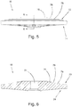
Figure 5 is a side elevational view of an embodiment of an expander cap used in the embodiment of the non-lethal projectile shown inFigure 1 ; -
Figure 6 is a cross sectional view of the expander cap shown inFigure 5 taken generally along line 6-6 ofFigure 5 ; -
Figure 7 is a top perspective view of the expander cap shown inFigure 5 ; -
Figure 8 is a top perspective view of an embodiment of an expander base used in the embodiment of the non-lethal projectile shown inFigure 1 ; -
Figure 9 is a top plan view of the expander base shown inFigure 8 ; -
Figure 10 is a cross-sectional view of the expander base shown inFigure 8 taken generally along line 10-10 ofFigure 9 ; -
Figure 11 is a top perspective view of an embodiment of a projectile frame used in the embodiment of the non-lethal projectile shown inFigure 1 ; -
Figure 12 is a cross-sectional view of the projectile frame shown inFigure 11 taken generally along line 12-12 ofFigure 11 ; -
Figure 13 is a perspective view of an embodiment of a guide expander used in the embodiment of the non-lethal projectile shown inFigure 1 ; -
Figure 14 is a cross-sectional view of the guide expander shown inFigure 13 taken generally along line 14-14 ofFigure 13 ; -
Figure 15 is a perspective view of an embodiment of a resilient expander used in the embodiment of the non-lethal projectile shown inFigure 1 ; -
Figure 16 is a side elevational view of the resilient expander shown inFigure 15 ; -
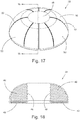
Figure 17 is a top perspective view of an embodiment of a marker packet used in the embodiment of the non-lethal projectile shown inFigure 1 ; -
Figure 18 is a cross sectional view of the marker packet shown inFigure 17 taken generally along line 18-18 ofFigure 17 ; -
Figure 19 is a side elevational view of another embodiment of a present invention non-lethal projectile; -
Figure 20 is a cross sectional perspective view of the non-lethal projectile shown inFigure 19 taken generally along line 20-20 ofFigure 19 ; -
Figure 21 is a cross sectional view of the non-lethal projectile shown inFigure 19 taken generally along line 21-21 ofFigure 19 ; -
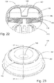
Figure 22 is an enlarged cross sectional view of the encircledregion 22 shown inFigure 21 ; -
Figure 23 is a top perspective view of another embodiment of a marker packet used in the embodiment of the non-lethal projectile shown inFigure 19 ; and, -
Figure 24 is a cross sectional view of the marker packet shown inFigure 23 taken generally along line 24-24 ofFigure 23 . - At the outset, it should be appreciated that like drawing numbers on different drawing views identify identical, or functionally similar, structural elements of the invention. While the present invention is described with respect to what is presently considered to be the preferred aspects, it is to be understood that the invention as claimed is not limited to the disclosed aspects.
- Furthermore, it is understood that this invention is not limited to the particular methodology, materials and modifications described and as such may, of course, vary. It is also understood that the terminology used herein is for the purpose of describing particular aspects only, and is not intended to limit the scope of the present invention, which is limited only by the appended claims.
- Unless defined otherwise, all technical and scientific terms used herein have the same meaning as commonly understood to one of ordinary skill in the art to which these embodiments belong. As used herein, the term "average" shall be construed broadly to include any calculation in which a result datum or decision is obtained based on a plurality of input data, which can include but is not limited to, weighted averages, yes or no decisions based on rolling inputs, etc. Moreover, as used herein, the phrases "comprises at least one of' and "comprising at least one of' in combination with a system or element is intended to mean that the system or element includes one or more of the elements listed after the phrase. For example, a device comprising at least one of: a first element; a second element; and, a third element, is intended to be construed as any one of the following structural arrangements: a device comprising a first element; a device comprising a second element; a device comprising a third element; a device comprising a first element and a second element; a device comprising a first element and a third element; a device comprising a first element, a second element and a third element; or, a device comprising a second element and a third element. A similar interpretation is intended when the phrase "used in at least one of:" is used herein. Furthermore, as used herein, "and/or" is intended to mean a grammatical conjunction used to indicate that one or more of the elements or conditions recited may be included or occur. For example, a device comprising a first element, a second element and/or a third element, is intended to be construed as any one of the following structural arrangements: a device comprising a first element; a device comprising a second element; a device comprising a third element; a device comprising a first element and a second element; a device comprising a first element and a third element; a device comprising a first element, a second element and a third element; or, a device comprising a second element and a third element.
- Although any methods, devices or materials similar or equivalent to those described herein can be used in the practice or testing of the invention, the preferred methods, devices, and materials are now described.
-
Non-lethal projectile 10 comprisesframe 12,guide expander 14,expander base 16,expander cap 18,resilient expander 20,marker packet 22 andcone 24.Projectile 10 is positioned withinshell 26.Volume 28 ofshell 26 acts as a combustion chamber. The propellant is ignited via a primer located inside a .38 caliber shell casing (not shown). The .38 caliber shell casing is positioned inbore 30 ofshell 26. The propellant is selected from those well known in the art and is not particularly germane to the present device. Upon ignition of the propellant, projectile 10 exits shell 26 in the direction of firing. Upon impact with a target,cone 24 collapses,expander base 16 expands outwardly,resilient expander 20 compresses and expands outwardly, andmarker packet 22 ruptures, thereby dispersing the payload and collectively absorbing kinetic energy from the movingprojectile 10 and decreasing its damage and/or injury to the target. -
Expander base 16 is arranged to "fail" thereby absorbing kinetic energy.Expander base 16 comprisesexpander base segments 64 which are connected by weakenedregions 66. Upon impact with a target, a longitudinal compression force is imparted oncone 24 and thereby on theresilient expander 20,expander cap 18,expander base 16 and guideexpander 14. As the foregoing elements compress, frame 12 slides relative to guideexpander 14 and is pushed againstexpander base 16.Frame 12 in turn causesexpander base segments 64 to be pushed outwardly. Provided sufficient force is imparted onbase segments 64, weakenedportions 66 fail thereby permitting further expansion ofbase segments 64. The expansion ofbase segments 64 in combination with the failure of weakenedportions 66 further absorbs kinetic energy of the movingprojectile 10. In the expanded form,expander base 16 forms a star-like structure. In addition to the foregoing absorption of energy, the inertia ofprojectile 10 is further dissipated by the compression ofexpander cap 18 againstbase 80 ofresilient expander 20. This action assists with the rupturing ofmarker packet 22, as described in further detail infra. It should be appreciated that althoughexpander base 16 andexpander cap 18 are depicted as separate elements joined together, a single element can also be formed. However, due to present savings in manufacturing, the two piece arrangement is preferred. -
Resilient expander 20 is formed from a flexible material, e.g., silicone. As non-lethal projectile 10 impacts a target,extension 82 ofresilient expander 20 is compressed in the direction depicted byuni-directional arrow 38 and thereby expands in the directions ofuni-directional arrows 40. It should be appreciated that although the expansion ofextension 82 is depicted by only twoarrows 40,extension 82 is cylindrical in shape. Therefore, asextension 82 is compressed in the direction ofarrow 38,extension 82 expands outwardly in substantially all radial directions including the directions depicted byarrows 40. Moreover, asexpander cap 18 impacts base 80 ofresilient expander 20,base 80 transfers kinetic energy to base 42 ofmarker packet 22, i.e., transfers kinetic energy in the direction ofuni-directional arrows 44. -
Resilient expander 20 assists in the dispersion ofpayload 46 frommarker packet 22 on the target.Expander 20 also absorbs inertia, i.e., kinetic energy, creates a fixture formarker packet 22 and acts as a safety barrier preventing components belowresilient expander 20 from impacting a target directly. In flight,marker packet 22 is stabilized incone 24 ofprojectile 10 byresilient expander 20. During impact,extension 82 expands outwardly intoinner surface 48 ofmarker packet 22 andbase 80 ofexpander 20 compresses againstbase 42 ofmarker packet 22, collectively creating a higher pressure vessel thereby dispersingpayload 46 in a desirable pattern. To ensure the plastic components of projectile 10 will not penetrate the target, e.g., guideexpander 14,expander base 16, andexpander cap 18,base 80 acts as a safety barrier blocking the plastic components from moving forward upon impact. The elasticity ofresilient expander 20 also absorbs some inertia from projectile 10 making it less likely to injure a target. - In an embodiment,
marker packet 22 is a partial toroid shaped component formed from a material such as polyethylene.Marker packet 22 acts as a pressure vessel when a target is hit. High pressure that develops upon impact in combination withsegments 50 allow for proper outward dispersion ofpayload 46 onto the target. In other words, a compressive force is applied to the impacting surface ofpacket 22, a compressive force is applied tobase 42 bybase 80 ofexpander 20, and a compressive force is applied to surface 48 byextension 82, collectively pushing inwardly onpayload 46. This collective force creates a higher pressure withinpacket 22 thereby providing the means to effectively dispersepayload 46 on a target.Segments 50 are defined and separated by etched or weakenedportions 52 in the top portion ofmarker packet 22. In short, upon reaching a sufficient pressure, weakenedportions 52 fail or open thereby permitting dispersion ofpayload 46. The foregoing arrangement ofmarker packet 22 also facilitates the dispersion of its kinetic energy over a larger surface area creating a projectile less likely to cause injury to a target. - In addition to the above described payloads that may be carried by the present invention non-lethal projectile, the payload may also include a tagging and/or marking agent, as well as an infrared liquid or powder. Tagging agents, such as forensic marking agents, provide greater capability for the present projectile, e.g., tagging a party prior to fleeing a scene for later identification and arrest. Thus, for example, a participant of a riot may be impacted with a present projectile carrying a forensic marking agent and even if that participant leaves the scene of the riot prior to arrest, law enforcement agents can later identify that person as a participant due to the presence of the marking agent. Such marking agents can effectively code a person, object, etc., for later identification. Forensic marking agents can be configured with unique formulas so that the later identification can provide information related to where the person was tagged or who tagged the person, i.e., each law enforcement agent could have a unique marking agent which will be undetectable by the person being tagged. Moreover, not only does the foregoing marking agent tag a person's clothing, but the marking agent also propagates to skin and unexposed clothing so that if a person removes the clothing that was actually impacted by the present invention projectile, the marking agents are still detectable later in time. An example of a forensic marking liquid is the SMARTWATER® product offered by SmartWater CSI LLC of Fort Lauderdale, Florida and SmartWater Technology Ltd. of London, England.
- Other embodiments of the present invention non-lethal projectile have also been developed.
Non-lethal projectile 110 comprisesframe 112,guide expander 114,expander base 116,expander cap 118,resilient layer 120,marker packet 122 andcone 124.Projectile 110 is positioned withinshell 126.Volume 128 ofshell 126 acts as a combustion chamber. The nature of firing projectile 110 is substantially the same as the firing of projectile 10 described above. However, upon impact with a target,cone 124 collapses,expander base 116 expands outwardly,resilient layer 120 compresses surface 142 ofmarker packet 122, andmarker packet 122 ruptures, thereby dispersing the payload and collectively absorbing kinetic energy from the moving projectile 110 and decreasing its damage and/or injury to the target. - Similar to the embodiment described above,
expander base 116 is arranged to "fail" thereby absorbing kinetic energy. Upon impact with a target, a longitudinal compression force is imparted oncone 124 and thereby on theresilient layer 120,expander cap 118,expander base 116 and guideexpander 114. As the foregoing elements compress, frame 112 slides relative to guideexpander 114 and is pushed againstexpander base 116.Frame 112 in turn causesexpander base 116 to fail, pushing thesegments forming base 116 outwardly, thereby absorbing kinetic energy of the movingprojectile 110. In the expanded form,expander base 116 forms a star-like structure. In addition to the foregoing absorption of energy, the inertia ofprojectile 110 is further dissipated by the compression ofexpander cap 118 againstresilient layer 120. This action assists with the rupturing ofmarker packet 122, as described in further detail infra. -
Resilient layer 120 is formed from a flexible material, e.g., silicone. As non-lethal projectile 110 impacts a target,resilient layer 120 is compressed againstseal layer 142 ofmarker packet 122. Moreover, asexpander cap 118 impactsresilient layer 120,expander cap 118 transfers kinetic energy to seallayer 142 ofmarker packet 122. -
Resilient layer 120 assists in the dispersion ofpayload 146 frommarker packet 122 on the target,layer 120 also absorbs inertia, i.e., kinetic energy, fills the gap betweencap 118 andlayer 142 and acts as a safety barrier preventing components belowresilient layer 120 from impacting a target directly. During impact,layer 120 compresses againstsealing layer 142 creating a higher pressure vessel thereby dispersingpayload 146 in a desirable pattern. To ensure the plastic components ofprojectile 110 will not penetrate the target, e.g.,guide expander 114,expander base 116, andexpander cap 118,layer 120 also acts as a safety barrier blocking the plastic components from moving forward upon impact. The elasticity oflayer 120 also absorbs some inertia from projectile 110 making it less likely to injure a target. - In an embodiment,
marker packet 122 is a partial toroid shapedcomponent comprising wall 150 formed from a material such as high density polyethylene (HDPE).Marker packet 122 further comprises sealinglayer 142.Layer 142 is secured to the base ofwall 150 by any means known in the art, e.g., induction sealing, and is formed from a material that is compatible withpayload 146 so thatlayer 142 does not deteriorate prior to use, e.g., during storage of the projectile. For example,layer 142 may be formed from ExpressWeb EFS 174 manufactured by Glenroy Inc. of Menomonee Falls, Wisconsin. Suitable sealing layers may include but are not limited to materials including at least one of: polyester; low density polyethylene; aluminum foil; and, linear low density polyethylene. It should be appreciated thatlayer 142 may also be formed as a multi-layer composite including some or all of the aforementioned materials.Marker packet 122 acts as a pressure vessel when a target is hit. High pressure that develops upon impact in combination withwall 150 allows for proper outward dispersion ofpayload 146 onto the target. In other words, a compressive force is applied to the impacting surface ofpacket 122, a compressive force is applied to sealinglayer 142 byresilient layer 120, collectively pushing inwardly onpayload 146. This collective force creates a higher pressure withinpacket 122 thereby providing the means to effectively dispersepayload 146 on a target.Wall 150 is defined and separated by etched or weakenedportions 152 in the top portion ofmarker packet 122. In short, weakenedportions 152 cause a controlled failure mode ofmarker packet 122 when pressurized by impact, i.e.,wall 150 fails along the length of each weakenedportions 152. The foregoing arrangement ofmarker packet 122 facilitates the dispersion of its kinetic energy over a larger surface area creating a projectile less likely to cause injury to a target. - In addition to the foregoing,
marker packet 122 comprisesinner surface 148. In this embodiment,inner surface 148 does not form a complete through hole inmarker packet 122. As can be best understood in view ofFigure 24 , the base of opening 190 does not contact sealinglayer 142. Thus,gap 192 is formed betweeninner surface 148 and sealinglayer 142. The gap may be larger or smaller than depicted in the figures, or alternatively, no gap may be present. It is believed that the size ofgap 192 also contributes to the nature of the dispersion ofpayload 146 during impact with a target. Embodiments falling within the scope of the claimed invention include full through holes, e.g.,marker packet 22, and partial through holes, e.g.,marker packet 122. Moreover, it is contemplated that no opening may be included, and that those embodiments will form a domed structure devoid of indentations or openings in the middle of the marker packet, - The present embodiments provide non-lethal projectiles that outperform alternate designs. For example, the present invention was compared against three alternate designs for viscous criterion (VC) and impact force. The foregoing tests used various impact velocities to measure impact force, dynamic deflection and impact velocity to quantify the performance of each design. The present embodiments provided lower impact force and lower viscous criterion than each other tested design.
- The impact of the present invention non-lethal projectile on a target creates two impacts of inertia on the target. The present invention causes a dispersion of inertia on the target. Upon impact, the present projectile provides an initial dispersion of inertia on the target, and subsequently as the frame and in turn the guide expander pushes into the expander base, a second dispersion of inertia on the target occurs. Furthermore, the size of the cone of the present invention causes a wide area dispersion of force on a target which spreads kinetic energy to more nerve endings thereby causing more pain compliance while decreasing injury due to lack of penetration.
- Thus, it is seen that the objects of the present invention are efficiently obtained, although modifications and changes to the invention should be readily apparent to those having ordinary skill in the art, which modifications are intended to be within the scope of the invention as disclosed in the appended claims.
-
- 10 - non-lethal projectile
- 12 - frame
- 14 - guide expander
- 16 - expander base
- 18 - expander cap
- 20 - resilient expander
- 22 - marker packet
- 24 - cone
- 26 - shell
- 28 - volume
- 30 - bore
- 38 - uni-directional arrow
- 40 - uni-directional arrow
- 42 - base
- 44 - uni-directional arrow
- 46 - payload
- 48 - inner surface
- 50 - segment
- 52 - weakened portion
- 54 - hollow frame body
- 56 - upper end cap
- 58 - through bore
- 60 - guide expander base
- 62 - cylindrical guide
- 64 - expander base segment
- 66 - weakened portion
- 68 - upper protrusion
- 70 - lower protrusion
- 72 - upper surface
- 74 - lower surface
- 76 - circular planar surface
- 78 - through bore
- 80 - base
- 82 - extension
- 84 - upper surface
- 86 - lower surface
- 110 - non-lethal projectile
- 112 - frame
- 114 - guide expander
- 116 - expander base
- 118 - expander cap
- 120 - resilient layer
- 122 - marker packet
- 124 - cone
- 126 - shell
- 128 - volume
- 130 - bore
- 142 - sealing layer
- 146 - payload
- 148 - inner surface
- 150 - wall
- 152 - weakened portion
- 190 - opening
- 192 - gap
Claims (10)
- A non-lethal projectile (10, 110) comprising:a frame (12, 112) comprising a substantially cylindrical hollow body (54), characterized by
a closed upper end and a through bore (58) centrally disposed within the closed upper end and coaxially arranged with the substantially cylindrical hollow body (54);a guide expander (14, 114) comprising a cylindrical guide (62) and a base (60), wherein the cylindrical guide (62) is disposed within the through bore (58) and longitudinally displaceable therein;an expander base (16, 116) comprising a plurality of segments (64), a lower protrusion (70) and an upper protrusion (68), wherein the guide expander (14, 114) contacts the lower protrusion (70) and each segment (64) of the plurality of segments (64) is connected to each adjacent segment by a weakened portion (66);an expander cap (18, 118) comprising an upper surface (72) comprising a plurality of offset circular planar surfaces (76) and a through bore (78) centrally disposed and contacting the upper protrusion (68) of the expander base (16, 116);a payload dispersion system comprising a resilient layer (20, 120) and a payload carrying packet (22, 122) comprising a hollow body comprising a lower surface, an upper surface, a volume formed by the lower surface and the upper surface, and a payload (46, 146) contained within the volume, wherein the upper surface of the payload carrying packet (22, 122) comprises a wall and at least one weakened portion (52, 152) within the wall, the lower surface of the payload carrying packet (22, 122) contacts an upper surface (84) of the resilient layer (20, 120), the upper surface (72) of the expander cap (18, 118) contacts a lower surface (86) of the resilient layer (20, 120) of the payload dispersion system; and,a cap arranged to enclose the payload carrying packet (22, 122), the resilient layer (20,120) and the expander cap (18, 118), and partially enclose the expander base (16, 116), wherein the payload (46, 146) is dispersed on or near a target upon impact by the non-lethal projectile (10, 110). - The non-lethal projectile (10, 110) of claim 1, wherein the hollow body of the payload carrying packet (22, 122) further comprises at least a partial opening centrally disposed, and the volume is formed by the lower surface, the at least a partial opening, and the upper surface.
- The non-lethal projectile (10) of claim 2, wherein the at least a partial opening in the payload carrying packet (22) comprises a through hole.
- The non-lethal projectile (10, 110) of one of the claims 1 to 3, wherein the wall of the upper surface of the payload carrying packet (22, 122) comprises a plurality of wall segments (50), and each of the plurality of wall segments (50) is connected to each adjacent wall segment (50) by a weakened portion (52).
- The non-lethal projectile (10, 110) of one of the claims 1 to 4, wherein the wall is formed from a thermoplastic material.
- The non-lethal projectile (10, 110) of claim 5, wherein the thermoplastic is a high density polyethylene.
- The non-lethal projectile (10, 110) of one of the claims 1 to 6, wherein the lower surface is formed from a multi-layer composition.
- The non-lethal projectile (10, 110) of claim 7 wherein the multi-layer composition comprises at least of: polyester; low density polyethylene; aluminum foil; and, linear low density polyethylene.
- The non-lethal projectile (10) of one of the claims 1 to 8, wherein the payload carrying packet (22) comprises at least a through hole centrally disposed, and the volume is formed by the lower surface, the through hole, and the upper surface, the resilient layer (20) further comprises a base (80) and an extension (82), and the extension (82) of the resilient layer (20) is disposed within the through hole.
- The non-lethal projectile (10) of one of the claims 1 to 9, wherein the resilient layer (20) of the payload dispersion system further comprises a base (80) and an extension (82), wherein the upper surface (72) of the expander cap (18) contacts a lower surface (86) of the base (80).
Applications Claiming Priority (2)
| Application Number | Priority Date | Filing Date | Title |
|---|---|---|---|
| US201461926728P | 2014-01-13 | 2014-01-13 | |
| PCT/US2014/044892 WO2015105526A1 (en) | 2014-01-13 | 2014-06-30 | Payload carrying arrangement for a non-lethal projectile |
Publications (3)
| Publication Number | Publication Date |
|---|---|
| EP3094945A1 EP3094945A1 (en) | 2016-11-23 |
| EP3094945A4 EP3094945A4 (en) | 2017-09-13 |
| EP3094945B1 true EP3094945B1 (en) | 2018-10-17 |
Family
ID=53524231
Family Applications (1)
| Application Number | Title | Priority Date | Filing Date |
|---|---|---|---|
| EP14877936.6A Not-in-force EP3094945B1 (en) | 2014-01-13 | 2014-06-30 | Payload carrying arrangement for a non-lethal projectile |
Country Status (6)
| Country | Link |
|---|---|
| US (1) | US9958242B2 (en) |
| EP (1) | EP3094945B1 (en) |
| CA (1) | CA2935920C (en) |
| HK (1) | HK1231546A1 (en) |
| IL (1) | IL246581B (en) |
| WO (1) | WO2015105526A1 (en) |
Families Citing this family (8)
| Publication number | Priority date | Publication date | Assignee | Title |
|---|---|---|---|---|
| US11209254B2 (en) * | 2016-03-09 | 2021-12-28 | Msato, Llc | Pellet shaped marking round for air rifles and pistols |
| WO2019040873A1 (en) | 2017-08-24 | 2019-02-28 | Nostromo, Llc | Mid-body marking projectile |
| SI25865A (en) * | 2019-06-28 | 2020-12-31 | AREX Proizvodnja orodij, naprav in storitve d.o.o., Šentjernej | Color marking missile |
| CN111707147B (en) * | 2020-06-28 | 2021-09-14 | 中国人民武装警察部队工程大学 | Energy attenuation type tear kinetic energy bullet |
| CN111765814B (en) * | 2020-07-10 | 2021-09-21 | 中国人民武装警察部队工程大学 | Compound anti-riot kinetic energy bullet with two-stage dissipation mechanism |
| US11473888B2 (en) * | 2020-08-25 | 2022-10-18 | General Dynamics OTS—Canada Inc. | Spotter ammunition projectile and method for making the same |
| US11287236B1 (en) * | 2020-11-04 | 2022-03-29 | Frank Dindl | Training cartridge with day/night/thermal visible signature |
| CN118451294A (en) * | 2021-12-08 | 2024-08-06 | Nl企业有限责任公司 | Projectile structure, launcher and launcher attachment |
Family Cites Families (33)
| Publication number | Priority date | Publication date | Assignee | Title |
|---|---|---|---|---|
| US3894492A (en) | 1973-07-12 | 1975-07-15 | Aai Corp | Deterrent ammunition |
| US3911824A (en) | 1973-07-13 | 1975-10-14 | Aai Corp | Deterrent ammunition projectile |
| US3865038A (en) * | 1973-07-13 | 1975-02-11 | Irwin R Barr | Deterrent ammunition projectile |
| GB7935724D0 (en) * | 1979-10-15 | 2001-12-05 | Secr Defence | Projectile for firing from a cartridge |
| USH114H (en) * | 1986-01-29 | 1986-08-05 | The United States Of America As Represented By The Secretary Of The Army | Practice projectile assembly |
| US5035183A (en) | 1990-03-12 | 1991-07-30 | David Luxton | Frangible nonlethal projectile |
| FR2750206B1 (en) * | 1996-06-21 | 1998-09-11 | Lacroix Soc E | NON-LETHAL PROJECTILE |
| GB0018593D0 (en) * | 2000-07-28 | 2000-09-13 | Brydges Price Richard I | Projectile for delivery of a tranquilliser |
| US6647890B2 (en) * | 2001-11-28 | 2003-11-18 | Guilford Engineering Associates, Inc. | Self-contained round having ring airfoil projectile and launcher therefor |
| US6736070B2 (en) * | 2002-03-06 | 2004-05-18 | Joseph C. Baltos | Passive action security systems |
| US7526998B2 (en) | 2003-02-10 | 2009-05-05 | Pepperball Technologies, Inc. | Stabilized non-lethal projectile systems |
| US7987790B1 (en) * | 2003-03-18 | 2011-08-02 | Scarr Kimball R | Ring airfoil glider expendable cartridge and glider launching method |
| US20050066849A1 (en) * | 2003-09-29 | 2005-03-31 | Kapeles John A. | Frangible non-lethal projectile |
| US7021219B1 (en) * | 2004-01-02 | 2006-04-04 | The United States Of America As Represented By The Secretary Of The Army | Non-lethal telescoping cartridge |
| DE102004017464B4 (en) | 2004-04-08 | 2006-05-18 | Nico-Pyrotechnik Hanns-Jürgen Diederichs GmbH & Co. KG | Patronized exercise ammunition |
| DE102004017466A1 (en) | 2004-04-08 | 2005-11-03 | Nico-Pyrotechnik Hanns-Jürgen Diederichs GmbH & Co. KG | Projectile with marking of the impact point |
| WO2006057658A2 (en) | 2004-04-09 | 2006-06-01 | Pepperball Technologies, Inc. | Primer launched projectile systems |
| US7143699B2 (en) * | 2004-04-19 | 2006-12-05 | Bnb Ballistics, Inc. | Liquid filled less lethal projectile |
| WO2006007738A1 (en) * | 2004-07-23 | 2006-01-26 | Ruag Ammotec | Bursting projectile |
| US7549376B1 (en) * | 2005-07-15 | 2009-06-23 | The United States Of America As Represented By The Secretary Of The Army | Non-lethal projectile carrier |
| DE102005053491B4 (en) | 2005-11-09 | 2015-05-13 | Rheinmetall Waffe Munition Gmbh | Projectile with marking of the impact point |
| US7287475B2 (en) * | 2006-01-03 | 2007-10-30 | Combined Systems, Inc. | Reloadable non-lethal training cartridge |
| US20080178728A1 (en) | 2007-01-25 | 2008-07-31 | Kapeles John A | Frangible non-lethal projectile |
| US20080178758A1 (en) | 2007-01-25 | 2008-07-31 | Kapeles John A | Frangible non-lethal projectile |
| US8056481B2 (en) * | 2007-03-13 | 2011-11-15 | Dindl Frank J | Controlled deceleration projectile |
| KR20100016159A (en) | 2007-04-01 | 2010-02-12 | 시큐리티 디바이시스 인터내셔널 아이엔씨. | Non-lethal projectile |
| US7913626B1 (en) * | 2007-07-17 | 2011-03-29 | The United States Of America As Represented By The Secretary Of The Army | Kinetic energy absorber |
| DE202008017664U1 (en) * | 2008-09-08 | 2010-04-22 | Dräger, Karl-Heinz | Device for distributing irritants or warfare agents |
| US8424456B2 (en) | 2009-10-05 | 2013-04-23 | Amtec Corporation | Non-dud signature training cartridge and projectile |
| US8485102B2 (en) | 2010-04-14 | 2013-07-16 | Alliant Techsystems, Inc. | Marking ammunition |
| SG179302A1 (en) | 2010-09-16 | 2012-04-27 | Advanced Material Engineering Pte Ltd | Projectile with strike point marking |
| EP2616757B1 (en) | 2010-09-17 | 2018-08-22 | Amtec Corporation | Pyrophoric projectile |
| US8915191B2 (en) | 2011-03-29 | 2014-12-23 | Kenneth R. Jones | Spin stabilized and/ or drag stabilized, blunt impact non-lethal projectile |
-
2014
- 2014-06-30 HK HK17104977.0A patent/HK1231546A1/en unknown
- 2014-06-30 CA CA2935920A patent/CA2935920C/en active Active
- 2014-06-30 WO PCT/US2014/044892 patent/WO2015105526A1/en not_active Ceased
- 2014-06-30 EP EP14877936.6A patent/EP3094945B1/en not_active Not-in-force
-
2016
- 2016-07-03 IL IL246581A patent/IL246581B/en active IP Right Grant
- 2016-07-13 US US15/209,428 patent/US9958242B2/en active Active
Also Published As
| Publication number | Publication date |
|---|---|
| IL246581A0 (en) | 2016-08-31 |
| CA2935920C (en) | 2021-06-22 |
| EP3094945A4 (en) | 2017-09-13 |
| EP3094945A1 (en) | 2016-11-23 |
| IL246581B (en) | 2021-02-28 |
| US20160320167A1 (en) | 2016-11-03 |
| US9958242B2 (en) | 2018-05-01 |
| WO2015105526A1 (en) | 2015-07-16 |
| HK1231546A1 (en) | 2017-12-22 |
| CA2935920A1 (en) | 2015-07-16 |
Similar Documents
| Publication | Publication Date | Title |
|---|---|---|
| US9958242B2 (en) | Payload carrying arrangement for a non-lethal projectile | |
| US8671841B2 (en) | Kinetic munition or projectile with controlled, non-lethal effects | |
| US8573571B2 (en) | Dissipative structures and related methods | |
| US20050229807A1 (en) | Liquid filled less lethal projectile | |
| US20070190292A1 (en) | Impact energy management method and system | |
| US5649466A (en) | Method of rapidly deploying volume-displacement devices for restraining movement of objects | |
| US8915191B2 (en) | Spin stabilized and/ or drag stabilized, blunt impact non-lethal projectile | |
| EP3303761B1 (en) | Destruction mechanism for a disolvable sealing device | |
| US20120204329A1 (en) | Helmet designs utilizing fluid-filled containers | |
| US20080178758A1 (en) | Frangible non-lethal projectile | |
| US20090101038A1 (en) | Frangible non-lethal projectile | |
| US20090071459A1 (en) | Systems, methods and apparatus for use in distributing irritant powder | |
| US20050066841A1 (en) | Non-lethal projectiles for delivering an inhibiting substance to a living target | |
| JP2008529747A (en) | Energy absorbing liner and shape matching layer for use in protective headgear | |
| KR20100016159A (en) | Non-lethal projectile | |
| US20160053843A1 (en) | Device for absorbing impact | |
| US6250226B1 (en) | Non-lethal ammunition with incapacitating effect | |
| CN113474614A (en) | Non-lethal projectile construction and launcher | |
| JP6283252B2 (en) | Punch and gas discharge device | |
| US20080178728A1 (en) | Frangible non-lethal projectile | |
| US8186275B1 (en) | Non-lethal projectile for dispersing payload upon target impact | |
| US9827943B2 (en) | Rupturable plate and inflator using same | |
| US20060218918A1 (en) | Pyrotechnic actuator | |
| KR102158122B1 (en) | Shell with ejectable shell base | |
| US12352549B2 (en) | Non-pyrotechnic diversionary device |
Legal Events
| Date | Code | Title | Description |
|---|---|---|---|
| PUAI | Public reference made under article 153(3) epc to a published international application that has entered the european phase |
Free format text: ORIGINAL CODE: 0009012 |
|
| 17P | Request for examination filed |
Effective date: 20160811 |
|
| AK | Designated contracting states |
Kind code of ref document: A1 Designated state(s): AL AT BE BG CH CY CZ DE DK EE ES FI FR GB GR HR HU IE IS IT LI LT LU LV MC MK MT NL NO PL PT RO RS SE SI SK SM TR |
|
| AX | Request for extension of the european patent |
Extension state: BA ME |
|
| RIN1 | Information on inventor provided before grant (corrected) |
Inventor name: SULLIVAN, GREGORY, BARRY Inventor name: THRASHER, DEAN, GREGORY |
|
| DAX | Request for extension of the european patent (deleted) | ||
| A4 | Supplementary search report drawn up and despatched |
Effective date: 20170816 |
|
| RIC1 | Information provided on ipc code assigned before grant |
Ipc: F42B 8/12 20060101ALI20170809BHEP Ipc: F42B 12/50 20060101ALI20170809BHEP Ipc: F42B 12/40 20060101ALI20170809BHEP Ipc: F42B 8/00 20060101AFI20170809BHEP |
|
| REG | Reference to a national code |
Ref country code: HK Ref legal event code: DE Ref document number: 1231546 Country of ref document: HK |
|
| GRAP | Despatch of communication of intention to grant a patent |
Free format text: ORIGINAL CODE: EPIDOSNIGR1 |
|
| STAA | Information on the status of an ep patent application or granted ep patent |
Free format text: STATUS: GRANT OF PATENT IS INTENDED |
|
| RIC1 | Information provided on ipc code assigned before grant |
Ipc: F42B 12/40 20060101ALI20180328BHEP Ipc: F42B 12/50 20060101ALI20180328BHEP Ipc: F42B 8/00 20060101AFI20180328BHEP Ipc: F42B 8/12 20060101ALI20180328BHEP |
|
| INTG | Intention to grant announced |
Effective date: 20180425 |
|
| GRAJ | Information related to disapproval of communication of intention to grant by the applicant or resumption of examination proceedings by the epo deleted |
Free format text: ORIGINAL CODE: EPIDOSDIGR1 |
|
| STAA | Information on the status of an ep patent application or granted ep patent |
Free format text: STATUS: REQUEST FOR EXAMINATION WAS MADE |
|
| GRAR | Information related to intention to grant a patent recorded |
Free format text: ORIGINAL CODE: EPIDOSNIGR71 |
|
| GRAS | Grant fee paid |
Free format text: ORIGINAL CODE: EPIDOSNIGR3 |
|
| STAA | Information on the status of an ep patent application or granted ep patent |
Free format text: STATUS: GRANT OF PATENT IS INTENDED |
|
| GRAA | (expected) grant |
Free format text: ORIGINAL CODE: 0009210 |
|
| STAA | Information on the status of an ep patent application or granted ep patent |
Free format text: STATUS: THE PATENT HAS BEEN GRANTED |
|
| INTC | Intention to grant announced (deleted) | ||
| AK | Designated contracting states |
Kind code of ref document: B1 Designated state(s): AL AT BE BG CH CY CZ DE DK EE ES FI FR GB GR HR HU IE IS IT LI LT LU LV MC MK MT NL NO PL PT RO RS SE SI SK SM TR |
|
| INTG | Intention to grant announced |
Effective date: 20180911 |
|
| REG | Reference to a national code |
Ref country code: GB Ref legal event code: FG4D |
|
| REG | Reference to a national code |
Ref country code: CH Ref legal event code: EP |
|
| REG | Reference to a national code |
Ref country code: IE Ref legal event code: FG4D |
|
| REG | Reference to a national code |
Ref country code: DE Ref legal event code: R096 Ref document number: 602014034454 Country of ref document: DE Ref country code: AT Ref legal event code: REF Ref document number: 1054581 Country of ref document: AT Kind code of ref document: T Effective date: 20181115 |
|
| REG | Reference to a national code |
Ref country code: NL Ref legal event code: MP Effective date: 20181017 |
|
| REG | Reference to a national code |
Ref country code: LT Ref legal event code: MG4D |
|
| REG | Reference to a national code |
Ref country code: AT Ref legal event code: MK05 Ref document number: 1054581 Country of ref document: AT Kind code of ref document: T Effective date: 20181017 |
|
| PG25 | Lapsed in a contracting state [announced via postgrant information from national office to epo] |
Ref country code: NL Free format text: LAPSE BECAUSE OF FAILURE TO SUBMIT A TRANSLATION OF THE DESCRIPTION OR TO PAY THE FEE WITHIN THE PRESCRIBED TIME-LIMIT Effective date: 20181017 |
|
| PG25 | Lapsed in a contracting state [announced via postgrant information from national office to epo] |
Ref country code: NO Free format text: LAPSE BECAUSE OF FAILURE TO SUBMIT A TRANSLATION OF THE DESCRIPTION OR TO PAY THE FEE WITHIN THE PRESCRIBED TIME-LIMIT Effective date: 20190117 Ref country code: PL Free format text: LAPSE BECAUSE OF FAILURE TO SUBMIT A TRANSLATION OF THE DESCRIPTION OR TO PAY THE FEE WITHIN THE PRESCRIBED TIME-LIMIT Effective date: 20181017 Ref country code: HR Free format text: LAPSE BECAUSE OF FAILURE TO SUBMIT A TRANSLATION OF THE DESCRIPTION OR TO PAY THE FEE WITHIN THE PRESCRIBED TIME-LIMIT Effective date: 20181017 Ref country code: LT Free format text: LAPSE BECAUSE OF FAILURE TO SUBMIT A TRANSLATION OF THE DESCRIPTION OR TO PAY THE FEE WITHIN THE PRESCRIBED TIME-LIMIT Effective date: 20181017 Ref country code: LV Free format text: LAPSE BECAUSE OF FAILURE TO SUBMIT A TRANSLATION OF THE DESCRIPTION OR TO PAY THE FEE WITHIN THE PRESCRIBED TIME-LIMIT Effective date: 20181017 Ref country code: IS Free format text: LAPSE BECAUSE OF FAILURE TO SUBMIT A TRANSLATION OF THE DESCRIPTION OR TO PAY THE FEE WITHIN THE PRESCRIBED TIME-LIMIT Effective date: 20190217 Ref country code: ES Free format text: LAPSE BECAUSE OF FAILURE TO SUBMIT A TRANSLATION OF THE DESCRIPTION OR TO PAY THE FEE WITHIN THE PRESCRIBED TIME-LIMIT Effective date: 20181017 Ref country code: BG Free format text: LAPSE BECAUSE OF FAILURE TO SUBMIT A TRANSLATION OF THE DESCRIPTION OR TO PAY THE FEE WITHIN THE PRESCRIBED TIME-LIMIT Effective date: 20190117 Ref country code: FI Free format text: LAPSE BECAUSE OF FAILURE TO SUBMIT A TRANSLATION OF THE DESCRIPTION OR TO PAY THE FEE WITHIN THE PRESCRIBED TIME-LIMIT Effective date: 20181017 Ref country code: AT Free format text: LAPSE BECAUSE OF FAILURE TO SUBMIT A TRANSLATION OF THE DESCRIPTION OR TO PAY THE FEE WITHIN THE PRESCRIBED TIME-LIMIT Effective date: 20181017 |
|
| PG25 | Lapsed in a contracting state [announced via postgrant information from national office to epo] |
Ref country code: GR Free format text: LAPSE BECAUSE OF FAILURE TO SUBMIT A TRANSLATION OF THE DESCRIPTION OR TO PAY THE FEE WITHIN THE PRESCRIBED TIME-LIMIT Effective date: 20190118 Ref country code: RS Free format text: LAPSE BECAUSE OF FAILURE TO SUBMIT A TRANSLATION OF THE DESCRIPTION OR TO PAY THE FEE WITHIN THE PRESCRIBED TIME-LIMIT Effective date: 20181017 Ref country code: AL Free format text: LAPSE BECAUSE OF FAILURE TO SUBMIT A TRANSLATION OF THE DESCRIPTION OR TO PAY THE FEE WITHIN THE PRESCRIBED TIME-LIMIT Effective date: 20181017 Ref country code: PT Free format text: LAPSE BECAUSE OF FAILURE TO SUBMIT A TRANSLATION OF THE DESCRIPTION OR TO PAY THE FEE WITHIN THE PRESCRIBED TIME-LIMIT Effective date: 20190217 Ref country code: SE Free format text: LAPSE BECAUSE OF FAILURE TO SUBMIT A TRANSLATION OF THE DESCRIPTION OR TO PAY THE FEE WITHIN THE PRESCRIBED TIME-LIMIT Effective date: 20181017 |
|
| REG | Reference to a national code |
Ref country code: DE Ref legal event code: R097 Ref document number: 602014034454 Country of ref document: DE |
|
| PG25 | Lapsed in a contracting state [announced via postgrant information from national office to epo] |
Ref country code: IT Free format text: LAPSE BECAUSE OF FAILURE TO SUBMIT A TRANSLATION OF THE DESCRIPTION OR TO PAY THE FEE WITHIN THE PRESCRIBED TIME-LIMIT Effective date: 20181017 Ref country code: DK Free format text: LAPSE BECAUSE OF FAILURE TO SUBMIT A TRANSLATION OF THE DESCRIPTION OR TO PAY THE FEE WITHIN THE PRESCRIBED TIME-LIMIT Effective date: 20181017 Ref country code: CZ Free format text: LAPSE BECAUSE OF FAILURE TO SUBMIT A TRANSLATION OF THE DESCRIPTION OR TO PAY THE FEE WITHIN THE PRESCRIBED TIME-LIMIT Effective date: 20181017 |
|
| PLBE | No opposition filed within time limit |
Free format text: ORIGINAL CODE: 0009261 |
|
| STAA | Information on the status of an ep patent application or granted ep patent |
Free format text: STATUS: NO OPPOSITION FILED WITHIN TIME LIMIT |
|
| PG25 | Lapsed in a contracting state [announced via postgrant information from national office to epo] |
Ref country code: SK Free format text: LAPSE BECAUSE OF FAILURE TO SUBMIT A TRANSLATION OF THE DESCRIPTION OR TO PAY THE FEE WITHIN THE PRESCRIBED TIME-LIMIT Effective date: 20181017 Ref country code: RO Free format text: LAPSE BECAUSE OF FAILURE TO SUBMIT A TRANSLATION OF THE DESCRIPTION OR TO PAY THE FEE WITHIN THE PRESCRIBED TIME-LIMIT Effective date: 20181017 Ref country code: EE Free format text: LAPSE BECAUSE OF FAILURE TO SUBMIT A TRANSLATION OF THE DESCRIPTION OR TO PAY THE FEE WITHIN THE PRESCRIBED TIME-LIMIT Effective date: 20181017 Ref country code: SM Free format text: LAPSE BECAUSE OF FAILURE TO SUBMIT A TRANSLATION OF THE DESCRIPTION OR TO PAY THE FEE WITHIN THE PRESCRIBED TIME-LIMIT Effective date: 20181017 |
|
| 26N | No opposition filed |
Effective date: 20190718 |
|
| PG25 | Lapsed in a contracting state [announced via postgrant information from national office to epo] |
Ref country code: SI Free format text: LAPSE BECAUSE OF FAILURE TO SUBMIT A TRANSLATION OF THE DESCRIPTION OR TO PAY THE FEE WITHIN THE PRESCRIBED TIME-LIMIT Effective date: 20181017 |
|
| REG | Reference to a national code |
Ref country code: DE Ref legal event code: R119 Ref document number: 602014034454 Country of ref document: DE |
|
| PG25 | Lapsed in a contracting state [announced via postgrant information from national office to epo] |
Ref country code: MC Free format text: LAPSE BECAUSE OF FAILURE TO SUBMIT A TRANSLATION OF THE DESCRIPTION OR TO PAY THE FEE WITHIN THE PRESCRIBED TIME-LIMIT Effective date: 20181017 |
|
| REG | Reference to a national code |
Ref country code: CH Ref legal event code: PL |
|
| GBPC | Gb: european patent ceased through non-payment of renewal fee |
Effective date: 20190630 |
|
| REG | Reference to a national code |
Ref country code: BE Ref legal event code: MM Effective date: 20190630 |
|
| PG25 | Lapsed in a contracting state [announced via postgrant information from national office to epo] |
Ref country code: TR Free format text: LAPSE BECAUSE OF FAILURE TO SUBMIT A TRANSLATION OF THE DESCRIPTION OR TO PAY THE FEE WITHIN THE PRESCRIBED TIME-LIMIT Effective date: 20181017 |
|
| PG25 | Lapsed in a contracting state [announced via postgrant information from national office to epo] |
Ref country code: DE Free format text: LAPSE BECAUSE OF NON-PAYMENT OF DUE FEES Effective date: 20200101 Ref country code: IE Free format text: LAPSE BECAUSE OF NON-PAYMENT OF DUE FEES Effective date: 20190630 Ref country code: GB Free format text: LAPSE BECAUSE OF NON-PAYMENT OF DUE FEES Effective date: 20190630 |
|
| PG25 | Lapsed in a contracting state [announced via postgrant information from national office to epo] |
Ref country code: CH Free format text: LAPSE BECAUSE OF NON-PAYMENT OF DUE FEES Effective date: 20190630 Ref country code: LI Free format text: LAPSE BECAUSE OF NON-PAYMENT OF DUE FEES Effective date: 20190630 Ref country code: LU Free format text: LAPSE BECAUSE OF NON-PAYMENT OF DUE FEES Effective date: 20190630 Ref country code: BE Free format text: LAPSE BECAUSE OF NON-PAYMENT OF DUE FEES Effective date: 20190630 |
|
| PG25 | Lapsed in a contracting state [announced via postgrant information from national office to epo] |
Ref country code: FR Free format text: LAPSE BECAUSE OF NON-PAYMENT OF DUE FEES Effective date: 20190630 |
|
| PG25 | Lapsed in a contracting state [announced via postgrant information from national office to epo] |
Ref country code: CY Free format text: LAPSE BECAUSE OF FAILURE TO SUBMIT A TRANSLATION OF THE DESCRIPTION OR TO PAY THE FEE WITHIN THE PRESCRIBED TIME-LIMIT Effective date: 20181017 |
|
| PG25 | Lapsed in a contracting state [announced via postgrant information from national office to epo] |
Ref country code: HU Free format text: LAPSE BECAUSE OF FAILURE TO SUBMIT A TRANSLATION OF THE DESCRIPTION OR TO PAY THE FEE WITHIN THE PRESCRIBED TIME-LIMIT; INVALID AB INITIO Effective date: 20140630 Ref country code: MT Free format text: LAPSE BECAUSE OF FAILURE TO SUBMIT A TRANSLATION OF THE DESCRIPTION OR TO PAY THE FEE WITHIN THE PRESCRIBED TIME-LIMIT Effective date: 20181017 |
|
| PG25 | Lapsed in a contracting state [announced via postgrant information from national office to epo] |
Ref country code: MK Free format text: LAPSE BECAUSE OF FAILURE TO SUBMIT A TRANSLATION OF THE DESCRIPTION OR TO PAY THE FEE WITHIN THE PRESCRIBED TIME-LIMIT Effective date: 20181017 |
|
| REG | Reference to a national code |
Ref country code: HK Ref legal event code: WD Ref document number: 1231546 Country of ref document: HK |