EP3094600B1 - Devices and methods for monitoring water flow through a chlorine-generating assembly - Google Patents
Devices and methods for monitoring water flow through a chlorine-generating assembly Download PDFInfo
- Publication number
- EP3094600B1 EP3094600B1 EP15702080.1A EP15702080A EP3094600B1 EP 3094600 B1 EP3094600 B1 EP 3094600B1 EP 15702080 A EP15702080 A EP 15702080A EP 3094600 B1 EP3094600 B1 EP 3094600B1
- Authority
- EP
- European Patent Office
- Prior art keywords
- assembly
- upper portion
- lower portion
- chlorine
- feature
- Prior art date
- Legal status (The legal status is an assumption and is not a legal conclusion. Google has not performed a legal analysis and makes no representation as to the accuracy of the status listed.)
- Active
Links
Images



Classifications
-
- C—CHEMISTRY; METALLURGY
- C02—TREATMENT OF WATER, WASTE WATER, SEWAGE, OR SLUDGE
- C02F—TREATMENT OF WATER, WASTE WATER, SEWAGE, OR SLUDGE
- C02F1/00—Treatment of water, waste water, or sewage
- C02F1/46—Treatment of water, waste water, or sewage by electrochemical methods
- C02F1/461—Treatment of water, waste water, or sewage by electrochemical methods by electrolysis
- C02F1/467—Treatment of water, waste water, or sewage by electrochemical methods by electrolysis by electrochemical disinfection; by electrooxydation or by electroreduction
- C02F1/4672—Treatment of water, waste water, or sewage by electrochemical methods by electrolysis by electrochemical disinfection; by electrooxydation or by electroreduction by electrooxydation
- C02F1/4674—Treatment of water, waste water, or sewage by electrochemical methods by electrolysis by electrochemical disinfection; by electrooxydation or by electroreduction by electrooxydation with halogen or compound of halogens, e.g. chlorine, bromine
-
- C—CHEMISTRY; METALLURGY
- C25—ELECTROLYTIC OR ELECTROPHORETIC PROCESSES; APPARATUS THEREFOR
- C25B—ELECTROLYTIC OR ELECTROPHORETIC PROCESSES FOR THE PRODUCTION OF COMPOUNDS OR NON-METALS; APPARATUS THEREFOR
- C25B1/00—Electrolytic production of inorganic compounds or non-metals
- C25B1/01—Products
- C25B1/24—Halogens or compounds thereof
- C25B1/26—Chlorine; Compounds thereof
-
- C—CHEMISTRY; METALLURGY
- C02—TREATMENT OF WATER, WASTE WATER, SEWAGE, OR SLUDGE
- C02F—TREATMENT OF WATER, WASTE WATER, SEWAGE, OR SLUDGE
- C02F2103/00—Nature of the water, waste water, sewage or sludge to be treated
- C02F2103/42—Nature of the water, waste water, sewage or sludge to be treated from bathing facilities, e.g. swimming pools
-
- C—CHEMISTRY; METALLURGY
- C02—TREATMENT OF WATER, WASTE WATER, SEWAGE, OR SLUDGE
- C02F—TREATMENT OF WATER, WASTE WATER, SEWAGE, OR SLUDGE
- C02F2201/00—Apparatus for treatment of water, waste water or sewage
- C02F2201/002—Construction details of the apparatus
- C02F2201/003—Coaxial constructions, e.g. a cartridge located coaxially within another
-
- C—CHEMISTRY; METALLURGY
- C02—TREATMENT OF WATER, WASTE WATER, SEWAGE, OR SLUDGE
- C02F—TREATMENT OF WATER, WASTE WATER, SEWAGE, OR SLUDGE
- C02F2201/00—Apparatus for treatment of water, waste water or sewage
- C02F2201/46—Apparatus for electrochemical processes
- C02F2201/461—Electrolysis apparatus
- C02F2201/46105—Details relating to the electrolytic devices
-
- C—CHEMISTRY; METALLURGY
- C02—TREATMENT OF WATER, WASTE WATER, SEWAGE, OR SLUDGE
- C02F—TREATMENT OF WATER, WASTE WATER, SEWAGE, OR SLUDGE
- C02F2201/00—Apparatus for treatment of water, waste water or sewage
- C02F2201/46—Apparatus for electrochemical processes
- C02F2201/461—Electrolysis apparatus
- C02F2201/46105—Details relating to the electrolytic devices
- C02F2201/4611—Fluid flow
-
- C—CHEMISTRY; METALLURGY
- C02—TREATMENT OF WATER, WASTE WATER, SEWAGE, OR SLUDGE
- C02F—TREATMENT OF WATER, WASTE WATER, SEWAGE, OR SLUDGE
- C02F2201/00—Apparatus for treatment of water, waste water or sewage
- C02F2201/46—Apparatus for electrochemical processes
- C02F2201/461—Electrolysis apparatus
- C02F2201/46105—Details relating to the electrolytic devices
- C02F2201/4612—Controlling or monitoring
- C02F2201/46145—Fluid flow
-
- C—CHEMISTRY; METALLURGY
- C02—TREATMENT OF WATER, WASTE WATER, SEWAGE, OR SLUDGE
- C02F—TREATMENT OF WATER, WASTE WATER, SEWAGE, OR SLUDGE
- C02F2209/00—Controlling or monitoring parameters in water treatment
- C02F2209/40—Liquid flow rate
-
- C—CHEMISTRY; METALLURGY
- C02—TREATMENT OF WATER, WASTE WATER, SEWAGE, OR SLUDGE
- C02F—TREATMENT OF WATER, WASTE WATER, SEWAGE, OR SLUDGE
- C02F2303/00—Specific treatment goals
- C02F2303/04—Disinfection
-
- C—CHEMISTRY; METALLURGY
- C02—TREATMENT OF WATER, WASTE WATER, SEWAGE, OR SLUDGE
- C02F—TREATMENT OF WATER, WASTE WATER, SEWAGE, OR SLUDGE
- C02F2305/00—Use of specific compounds during water treatment
- C02F2305/02—Specific form of oxidant
-
- E—FIXED CONSTRUCTIONS
- E04—BUILDING
- E04H—BUILDINGS OR LIKE STRUCTURES FOR PARTICULAR PURPOSES; SWIMMING OR SPLASH BATHS OR POOLS; MASTS; FENCING; TENTS OR CANOPIES, IN GENERAL
- E04H4/00—Swimming or splash baths or pools
- E04H4/12—Devices or arrangements for circulating water, i.e. devices for removal of polluted water, cleaning baths or for water treatment
- E04H4/1281—Devices for distributing chemical products in the water of swimming pools
Definitions
- the present disclosure generally relates to devices and methods for detecting and/or monitoring water flow through a chlorine-generating or other assembly.
- a flow stream from a body of water is passed through an electrolytic cell or other chlorine-generating assembly to oxide halide ions of the water by electrolysis to form hypohalic acid, hypohalite ions or both to disinfect or "chlorinate" the water.
- the treated flow stream is then returned to the body of water.
- Some assemblies for chlorinating water by electrolysis include a flow sensor that senses if water is flowing through the assembly.
- a flow sensor sometimes referred to as a gas trap sensor, includes an electrode that detects flow so long as there is conductivity between the electrode and one of the chlorine-generating electrode plates of the chlorine-generating assembly.
- the electrolytic process generates gas bubbles that are pushed out of the assembly by the water flow.
- the generated gas bubbles build up and break the connection between the gas flow electrode and the chlorine-generating electrode plates.
- water flowing at a rate lower than approximately 113,6 liter per minute (30 gallons per minute / GPM) gas continues to build in the flow sensor faster than the water flow can push it out.
- the assembly is designed in some embodiments so that a flow sensor is able to detect water flow even in low water flow situations, for example water flowing at a rate less than approximately 113,6 liter per minute (30 GPM)
- the assembly includes a flow channel that narrows from an inlet end of the assembly to an outlet end of the assembly to increase the velocity of the water flowing through the flow channel.
- the assembly also includes a water delivery mechanism that facilitates the delivery of water through the flow sensor and thus allows the flow sensor to detect the water flow even in low flow situations.
- the assembly is configured so that it can be locked and unlocked with a quarter turn. Further, in some embodiments, the assembly includes a keying feature that ensures the assembly is locked in the correct orientation.
- Certain aspects and features of the present disclosure relate to apparatuses and methods for sanitizing and protecting water from the growth of microorganisms, such as bacteria, virii, fungi, algae, and the like.
- microorganisms such as bacteria, virii, fungi, algae, and the like.
- Such sanitation and protection can be used for water in a variety of applications, including swimming pools, hot tubs, spas, as well as wastewater treatment facilities, cooling towers, and the like.
- FIG 1 illustrates one non-limiting example of a chlorine-generating assembly 10.
- Chlorine-generating assembly 10 includes an upper portion 12 and a lower portion 14.
- Chlorine-generating assembly 10 includes a flow channel 32 ( Figure 3 ), through which a plurality of chlorine-generating electrode plates 24 generally extend.
- Chlorine-generating electrode plates 24 may be formed of any suitable material, including but not limited to, titanium and may be uncoated or coated with a precious or semi-precious metal, such as platinum, ruthenium, or iridium.
- the lower portion 14 includes an inlet 26, an outlet 28, and a cavity 29 between inlet 26 and outlet 28.
- the flow channel 32 is received within cavity 29 of lower portion 14. Since upper portion 12 is removable with respect to lower portion 14, the chlorine-generating electrode plates 24 can be easily accessed and repaired or replaced when needed.
- chlorine generating assembly may have any suitable configuration and is not limited to the disclosed two-piece arrangement.
- Assembly 10 is designed so that water flows through flow channel 32, and thus across chlorine-generating electrode plates 24, in a flow direction 30.
- upper portion 12 also includes a chamber 37 that is separated from flow channel 32 by a plate 39.
- a venturi tube 38 and a flow sensor 20 extend through plate 39 and are in fluid communication with both the chamber 37 and the flow channel 32.
- Flow sensor 20 includes a flow sensor electrode 22. When conductivity exists in water flowing between flow sensor electrode 22 and chlorine-generating electrode plates 24, the flow sensor 20 senses water flow and returns a flow condition. When the connection between the flow sensor electrode 22 and the chlorine-generating electrode plates 24 is broken, the flow sensor 20 is unable to sense water flow and returns a no-flow condition, even if water is flowing through flow channel 32.
- the connection can be broken, for example, when gas bubbles generated as part of the chlorine-generating electrolytic process build up in the assembly 10 faster than the water flow pushes them and break the connection between the flow sensor electrode 22 and the chlorine-generating electrode plates 24.
- the venturi tube 38 evacuates air from the chamber 37 and water moves through flow sensor 20 into chamber 37.
- the water pushes gas bubbles generated as part of the electrolytic process out of the assembly at a faster rate than the gas bubbles are produced so that water continually covers the flow sensor electrode 22 and a connection is maintained between the flow sensor electrode 22 and the chlorine-generating electrode plates 24. Therefore, the flow sensor 20 senses flow and returns a flow condition.
- the flow channel 32 narrows from the inlet side 34 of the channel 32 toward the outlet side 36 of the channel 32.
- the narrowing of the flow channel 32 causes the velocity of the water to increase as it flows through the flow channel 32.
- the assembly 10 also includes a water delivery mechanism 40, shown in Figure 5 .
- the longitudinal axis of the water delivery mechanism 40 is generally aligned with at least a portion of the flow sensor electrode 22 of the flow sensor 20, although water delivery mechanism 40 can be aligned differently.
- Water delivery mechanism 40 is designed to act as a fountain that helps direct water flowing through flow channel 32 into contact with flow sensor electrode 22 of flow sensor 20, even in low flow situations and even when air is present inside chamber 37. In this way, the water delivery mechanism 40 helps bridge any gaps between the flow sensor electrode 22 and the chlorine-generating electrode plates 24 so that the flow sensor 20 senses water flow even in low flow situations, such as under approximately 113,6 liter per minute (30 GPM) or even as low as approximately 37,85 liter per minute (10 GPM) or lower.
- water delivery mechanism 40 includes a scooped portion 43 configured to scoop up water flowing through flow channel 32 and direct it to flow sensor electrode 22.
- the scooped portion 43 is positioned so that water flowing through flow channel 32 contacts the concave surface of the scooped portion 43 and travels upward toward flow sensor electrode 22. Because the flow channel 32 narrows, the water flow velocity increases and even more water is pushed across flow sensor electrode 22 via the water delivery mechanism 40.
- upper portion 12 includes a collar 15 that is rotatable with respect to a top surface 13 of the upper portion 12 and thus with respect to chlorine-generating electrode plates 24.
- Top surface 13 may also include a viewing window 16 that is at least partially transparent so that at least some of the internal components may be viewed when the assembly 10 is assembled.
- the lower portion 14 is opaque and the transparent viewing window 16 is arranged so that at least part of the top surfaces of the chlorine-generating electrode plates 24 is visible when the chlorine-generating electrode plates 24 are disposed within the opaque lower portion 14.
- a cable 18 may extend through the top surface 13 of the upper portion 12.
- Non-limiting embodiments of assembly 10 can include various other features if desired.
- upper portion 12 and lower portion 14 can be designed to move into a locked position with a quarter-turn of the upper portion 12 relative to the lower portion 14, as illustrated in Figures 7a-7b .
- collar 15 of upper portion 12 can include two or more abutments 44 that rotatably lock with respect to two or more flanges 42 of lower portion 14.
- collar 15 of upper portion 12 includes flanges 42 and lower portion 14 includes abutments 44.
- collar 15 is rotatable with respect to top surface 13 and chlorine-generating electrode plates 24.
- collar 15 can be rotated with respect to chlorine-generating electrode plates 24 and lower portion 14 to lock or unlock the assembly.
- the upper portion 12 is locked with respect to the lower portion 14.
- the two abutments 44 are approximately 180 degrees from one another and the two flanges 42 are approximately 180 degrees from one another.
- one of the portions is rotated with respect to the other portion about a longitudinal axis of the portion until the abutments 44 are no longer aligned with the two flanges 42.
- the upper portion 12 is rotated approximately 90 degrees relative to the lower portion 14.
- Collar 15 of upper portion 12 may also include gripping tabs 46 that facilitate locking and unlocking of the assembly.
- the chlorine-generating assembly 10 described above is configured such that water must flow in a particular flow direction 30 to function properly. Therefore, it is important that the upper portion 12 be assembled correctly with respect to the lower portion 14 so that the water flows in flow direction 30 through upper portion 12.
- the assembly 10 may include a key feature that ensures upper portion 12 is aligned correctly with respect to lower portion 14. If included, the key feature can take any suitable form.
- Figure 8 cavity 29 of lower portion 14 includes a ramped surface 50 and a recess 52.
- a protrusion 48 extending from the bottom surface of upper portion 12 includes a tab 54 that is configured to slide along ramped surface 50 and be guided into recess 52. When tab 54 is received within recess 52, the assembly 10 is assembled correctly and the lower portion 14 and upper portion 12 are capable of being locked together by rotating collar 15 relative to lower portion 14 as described above.
- protrusion 48 includes a plurality of slots 56 that receive a corresponding plurality of ribs 58 projecting from cavity 29 of lower portion 14 when the assembly 10 is assembled correctly.
- narrowing flow channel and water delivery mechanism which both facilitate detection of water flow in low flow situations, have been described above with respect to a chlorine-generating assembly, they can be incorporated into any suitable structure when it is desired that flow be sensed in low flow situations. Moreover, any or all of the disclosed features may be used with any chlorine-generating assembly or other suitable structure and are not limited to use with the specific assembly 10 depicted and described herein.
Landscapes
- Chemical & Material Sciences (AREA)
- Engineering & Computer Science (AREA)
- Chemical Kinetics & Catalysis (AREA)
- Electrochemistry (AREA)
- Organic Chemistry (AREA)
- Water Supply & Treatment (AREA)
- Hydrology & Water Resources (AREA)
- Environmental & Geological Engineering (AREA)
- Life Sciences & Earth Sciences (AREA)
- General Chemical & Material Sciences (AREA)
- Inorganic Chemistry (AREA)
- Materials Engineering (AREA)
- Metallurgy (AREA)
- Water Treatment By Electricity Or Magnetism (AREA)
- Measuring Volume Flow (AREA)
- Indicating Or Recording The Presence, Absence, Or Direction Of Movement (AREA)
Description
- The present disclosure generally relates to devices and methods for detecting and/or monitoring water flow through a chlorine-generating or other assembly.
- During electrolytic purification of water, a flow stream from a body of water is passed through an electrolytic cell or other chlorine-generating assembly to oxide halide ions of the water by electrolysis to form hypohalic acid, hypohalite ions or both to disinfect or "chlorinate" the water. The treated flow stream is then returned to the body of water.
- Some assemblies for chlorinating water by electrolysis include a flow sensor that senses if water is flowing through the assembly. Such a flow sensor, sometimes referred to as a gas trap sensor, includes an electrode that detects flow so long as there is conductivity between the electrode and one of the chlorine-generating electrode plates of the chlorine-generating assembly. The electrolytic process generates gas bubbles that are pushed out of the assembly by the water flow. When water is not flowing through the assembly, the generated gas bubbles build up and break the connection between the gas flow electrode and the chlorine-generating electrode plates. However, in low flow situations, for example water flowing at a rate lower than approximately 113,6 liter per minute (30 gallons per minute / GPM) gas continues to build in the flow sensor faster than the water flow can push it out. The buildup of gas breaks the connection between the gas flow electrode and the chlorine-generating electrode plates and the flow sensor is unable to sense the water flow and erroneously returns a "no flow" condition even though water is flowing through the assembly. A similar device is disclosed in
US 5,460,706 . - The term embodiment and like terms are intended to refer broadly to all of the subject matter of this disclosure and the claims below. Statements containing these terms should be understood not to limit the subject matter described herein or to limit the meaning or scope of the claims below. Embodiments of the present disclosure covered herein are defined by the claims below, not this summary. This summary is a high-level overview of various aspects of the disclosure and introduces some of the concepts that are further described in the Detailed Description section below. This summary is not intended to identify key or essential features of the claimed subject matter, nor is it intended to be used in isolation to determine the scope of the claimed subject matter. The subject matter should be understood by reference to appropriate portions of the entire specification of this disclosure, any or all drawings and each claim.
- Aspects of the present disclosure relate to improved chlorine-generating assemblies and methods. More particularly, the assembly is designed in some embodiments so that a flow sensor is able to detect water flow even in low water flow situations, for example water flowing at a rate less than approximately 113,6 liter per minute (30 GPM) According to the invention, the assembly includes a flow channel that narrows from an inlet end of the assembly to an outlet end of the assembly to increase the velocity of the water flowing through the flow channel. The assembly also includes a water delivery mechanism that facilitates the delivery of water through the flow sensor and thus allows the flow sensor to detect the water flow even in low flow situations. In some embodiments, the assembly is configured so that it can be locked and unlocked with a quarter turn. Further, in some embodiments, the assembly includes a keying feature that ensures the assembly is locked in the correct orientation.
- Illustrative embodiments of the present disclosure are described in detail below with reference to the following drawing figures:
-
FIG. 1 is a perspective view of a chlorine-generating assembly according to one embodiment, shown with the upper and lower portions disassembled. -
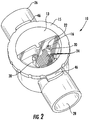
FIG. 2 is a top perspective view of the chlorine-generating assembly ofFIG. 1 , shown with the upper and lower portions assembled together. -
FIG. 3 is a top cut-away perspective view of select components of the chlorine-generating assembly ofFIG. 1 . -
FIG. 4 is a partial cut-away view of the chlorine-generating assembly ofFIG. 1 . -
FIG. 5 is a partial cut-away schematic of the chlorine-generating assembly ofFIG. 1 . -
FIG. 6 is a bottom perspective view of the chlorine-generating assembly ofFIG. 1 , shown with the upper and lower portions positioned with respect to one another. -
FIG. 7a is a top view of the chlorine-generating assembly ofFIG. 1 , shown with the upper and lower portions assembled together and in an unlocked position. -
FIG. 7b is a top view of the chlorine-generating assembly ofFIG. 1 , shown with the upper and lower portions assembled together and in a locked position. -
FIG. 8 is a partial cutaway view of a locking key of a chlorine-generating assembly according to one embodiment. -
FIG. 9 is a top perspective view of a lower portion according to one embodiment. -
FIG. 10 is a bottom perspective view of an upper portion according to one embodiment. - Certain aspects and features of the present disclosure relate to apparatuses and methods for sanitizing and protecting water from the growth of microorganisms, such as bacteria, virii, fungi, algae, and the like. Such sanitation and protection can be used for water in a variety of applications, including swimming pools, hot tubs, spas, as well as wastewater treatment facilities, cooling towers, and the like.
-
Figure 1 illustrates one non-limiting example of a chlorine-generatingassembly 10. Chlorine-generatingassembly 10 includes anupper portion 12 and alower portion 14. Chlorine-generating assembly 10 includes a flow channel 32 (Figure 3 ), through which a plurality of chlorine-generatingelectrode plates 24 generally extend. Chlorine-generatingelectrode plates 24 may be formed of any suitable material, including but not limited to, titanium and may be uncoated or coated with a precious or semi-precious metal, such as platinum, ruthenium, or iridium. - The
lower portion 14 includes aninlet 26, anoutlet 28, and acavity 29 betweeninlet 26 andoutlet 28. Whenupper portion 12 andlower portion 14 are assembled together, theflow channel 32 is received withincavity 29 oflower portion 14. Sinceupper portion 12 is removable with respect tolower portion 14, the chlorine-generatingelectrode plates 24 can be easily accessed and repaired or replaced when needed. Although illustrated as a two-piece assembly, chlorine generating assembly may have any suitable configuration and is not limited to the disclosed two-piece arrangement. -
Assembly 10 is designed so that water flows throughflow channel 32, and thus across chlorine-generatingelectrode plates 24, in aflow direction 30. As shown inFigure 4 ,upper portion 12 also includes achamber 37 that is separated fromflow channel 32 by aplate 39. Aventuri tube 38 and aflow sensor 20 extend throughplate 39 and are in fluid communication with both thechamber 37 and theflow channel 32.Flow sensor 20 includes aflow sensor electrode 22. When conductivity exists in water flowing betweenflow sensor electrode 22 and chlorine-generatingelectrode plates 24, theflow sensor 20 senses water flow and returns a flow condition. When the connection between theflow sensor electrode 22 and the chlorine-generatingelectrode plates 24 is broken, theflow sensor 20 is unable to sense water flow and returns a no-flow condition, even if water is flowing throughflow channel 32. The connection can be broken, for example, when gas bubbles generated as part of the chlorine-generating electrolytic process build up in theassembly 10 faster than the water flow pushes them and break the connection between theflow sensor electrode 22 and the chlorine-generatingelectrode plates 24. When water is flowing through theflow channel 32 at a sufficient rate (in some cases, at a rate of approximately 113,6 liter per minute (30 GPM) or above), theventuri tube 38 evacuates air from thechamber 37 and water moves throughflow sensor 20 intochamber 37. As water moves throughflow sensor 20, the water pushes gas bubbles generated as part of the electrolytic process out of the assembly at a faster rate than the gas bubbles are produced so that water continually covers theflow sensor electrode 22 and a connection is maintained between theflow sensor electrode 22 and the chlorine-generatingelectrode plates 24. Therefore, theflow sensor 20 senses flow and returns a flow condition. - In some embodiments, as shown in
Figure 3 , theflow channel 32 narrows from theinlet side 34 of thechannel 32 toward theoutlet side 36 of thechannel 32. The narrowing of theflow channel 32 causes the velocity of the water to increase as it flows through theflow channel 32. Theassembly 10 also includes awater delivery mechanism 40, shown inFigure 5 . As illustrated, the longitudinal axis of thewater delivery mechanism 40 is generally aligned with at least a portion of theflow sensor electrode 22 of theflow sensor 20, althoughwater delivery mechanism 40 can be aligned differently. -
Water delivery mechanism 40 is designed to act as a fountain that helps direct water flowing throughflow channel 32 into contact withflow sensor electrode 22 offlow sensor 20, even in low flow situations and even when air is present insidechamber 37. In this way, thewater delivery mechanism 40 helps bridge any gaps between theflow sensor electrode 22 and the chlorine-generatingelectrode plates 24 so that theflow sensor 20 senses water flow even in low flow situations, such as under approximately 113,6 liter per minute (30 GPM) or even as low as approximately 37,85 liter per minute (10 GPM) or lower. In some embodiments,water delivery mechanism 40 includes a scoopedportion 43 configured to scoop up water flowing throughflow channel 32 and direct it to flowsensor electrode 22. As illustrated, the scoopedportion 43 is positioned so that water flowing throughflow channel 32 contacts the concave surface of the scoopedportion 43 and travels upward towardflow sensor electrode 22. Because theflow channel 32 narrows, the water flow velocity increases and even more water is pushed acrossflow sensor electrode 22 via thewater delivery mechanism 40. - In some cases, as shown in
Figures 1-2 ,upper portion 12 includes acollar 15 that is rotatable with respect to atop surface 13 of theupper portion 12 and thus with respect to chlorine-generatingelectrode plates 24.Top surface 13 may also include aviewing window 16 that is at least partially transparent so that at least some of the internal components may be viewed when theassembly 10 is assembled. For example, in some embodiments, thelower portion 14 is opaque and thetransparent viewing window 16 is arranged so that at least part of the top surfaces of the chlorine-generatingelectrode plates 24 is visible when the chlorine-generatingelectrode plates 24 are disposed within the opaquelower portion 14. As shown inFigures 1-2 , acable 18 may extend through thetop surface 13 of theupper portion 12. - Non-limiting embodiments of
assembly 10 can include various other features if desired. For example,upper portion 12 andlower portion 14 can be designed to move into a locked position with a quarter-turn of theupper portion 12 relative to thelower portion 14, as illustrated inFigures 7a-7b . Specifically, as shown inFigure 6 ,collar 15 ofupper portion 12 can include two ormore abutments 44 that rotatably lock with respect to two ormore flanges 42 oflower portion 14. In other embodiments,collar 15 ofupper portion 12 includesflanges 42 andlower portion 14 includesabutments 44. As mentioned above,collar 15 is rotatable with respect totop surface 13 and chlorine-generatingelectrode plates 24. Once chlorine-generatingelectrode plates 24 are positioned withinlower portion 14,collar 15 can be rotated with respect to chlorine-generatingelectrode plates 24 andlower portion 14 to lock or unlock the assembly. Specifically, when eachabutment 44 is aligned with one of theflanges 42, theupper portion 12 is locked with respect to thelower portion 14. In some embodiments, the twoabutments 44 are approximately 180 degrees from one another and the twoflanges 42 are approximately 180 degrees from one another. To unlock theupper portion 12 with respect to thelower portion 14, one of the portions is rotated with respect to the other portion about a longitudinal axis of the portion until theabutments 44 are no longer aligned with the twoflanges 42. In some embodiments, theupper portion 12 is rotated approximately 90 degrees relative to thelower portion 14. Such a design allows theassembly 10 to be assembled into a locked position and disassembled without requiring the use of tools.Collar 15 ofupper portion 12 may also include grippingtabs 46 that facilitate locking and unlocking of the assembly. - The chlorine-generating
assembly 10 described above is configured such that water must flow in aparticular flow direction 30 to function properly. Therefore, it is important that theupper portion 12 be assembled correctly with respect to thelower portion 14 so that the water flows inflow direction 30 throughupper portion 12. To ensure that the upper portion 12 (and, in turn, itswater delivery mechanism 40 and narrowing flow channel 32) are installed correctly, theassembly 10 may include a key feature that ensuresupper portion 12 is aligned correctly with respect tolower portion 14. If included, the key feature can take any suitable form. One of many examples is illustrated inFigure 8 . As shown inFigure 8 ,cavity 29 oflower portion 14 includes a rampedsurface 50 and arecess 52. Aprotrusion 48 extending from the bottom surface ofupper portion 12 includes atab 54 that is configured to slide along rampedsurface 50 and be guided intorecess 52. Whentab 54 is received withinrecess 52, theassembly 10 is assembled correctly and thelower portion 14 andupper portion 12 are capable of being locked together by rotatingcollar 15 relative to lowerportion 14 as described above. In another non-limiting embodiment,protrusion 48 includes a plurality ofslots 56 that receive a corresponding plurality ofribs 58 projecting fromcavity 29 oflower portion 14 when theassembly 10 is assembled correctly. When theupper portion 12 is assembled incorrectly (i.e., thewater delivery mechanism 40 andflow channel 32 are not aligned correctly with respect to the lower portion 14), theribs 58 are not received in theslots 56 and prevent locking of theupper portion 12 with thelower portion 14. These key features are illustrative only; numerous other key features may be used instead to ensure thatupper portion 12 is assembled properly with respect tolower portion 14. - Although the narrowing flow channel and water delivery mechanism, which both facilitate detection of water flow in low flow situations, have been described above with respect to a chlorine-generating assembly, they can be incorporated into any suitable structure when it is desired that flow be sensed in low flow situations. Moreover, any or all of the disclosed features may be used with any chlorine-generating assembly or other suitable structure and are not limited to use with the
specific assembly 10 depicted and described herein. - Different arrangements of the components depicted in the drawings or described above, as well as components and steps not shown or described are possible. Similarly, some features and subcombinations are useful and may be employed without reference to other features and subcombinations. Embodiments of the invention have been described for illustrative and not restrictive purposes, and alternative embodiments will become apparent to readers of this patent. Accordingly, the present invention is not limited to the embodiments described above or depicted in the drawings, and various embodiments and modifications can be made without departing from the scope of the claims below.
Claims (12)
- An assembly (10) for electrolytic purification comprising:(a) an inlet (26) and an outlet (28) and a flow channel (32) extending between and in fluid communication with the inlet (26) and the outlet (28),(b) a plurality of chlorine-generating electrode plates (24) disposed within the flow channel (32);(c) a flow sensor (20) in fluid communication with the flow channel (32), wherein the flow sensor (20) comprises a flow sensor electrode (22); and(d) a water delivery mechanism (40) positioned within the flow channel (32) and configured to alter a direction of water flowing through the flow channel (32) so that the water is urged into contact with the flow sensor electrode (22), wherein the flow channel (32) narrows from the inlet (26) toward the outlet (28).
- The assembly of claim 1, wherein a longitudinal axis of the water delivery mechanism (40) intersects at least a portion of the flow sensor electrode (22).
- The assembly of claim 1, wherein the water delivery mechanism (40) comprises a scooped portion (43) and wherein a concave surface of the scooped portion (43) faces the inlet (26).
- The assembly of claim 1, wherein the assembly comprises an upper portion (12) and a lower portion (14) that are rotatable with respect to one another to move the assembly (10) between an unlocked position and a locked position by rotating the upper portion (12) relative to the lower portion (14).
- The assembly of claim 4, wherein:one of the upper portion (12) and the lower portion (14) comprises at least two abutments (44) and the other of the upper portion (12) and the lower portion (14) comprises at least two flanges (42); andthe assembly (10) is in the locked position when one of the at least two abutments (44) cooperates with one of the at least two flanges (42); andthe assembly (10) is in the unlocked position when the at least two abutments (44) are not aligned with respect to the at least two flanges (42).
- The assembly of claim 5, wherein the upper portion (12) comprises a collar (15) that is rotatable with respect to a top surface (13) of the upper portion (12).
- The assembly of claim 1, wherein the assembly comprises a transparent portion arranged so that at least part of a top surface (13) of the plurality of chlorine-generating electrode plates (24) is visible through the transparent portion when the plurality of chlorine-generating electrode plates (24) is disposed within the flow channel (32).
- The assembly of claim 1, wherein a cable (18) extends out of a top surface (13) of the upper portion (12).
- The assembly according to claim 1, wherein the assembly further comprises:an upper portion (12) and a lower portion (14) that are rotatable with respect to one another; anda keying feature that prevents the assembly from moving into a locked position when the upper portion (12) and the lower portion (14) are not aligned in a correct orientation, the keying feature comprising a first feature on the upper portion (12) and a second feature on the lower portion (14),the first feature is a tab (54);the second feature comprises a ramp (50) and a recess (52); andthe tab (54) is configured to slide along the ramp (50) as the assembly moves from the unlocked position towards the locked position and wherein the tab (54) is received in the recess (52) when the assembly is in the correct orientation.
- The assembly of claim 1, wherein the assembly further comprises:an upper portion (12) and a lower portion (14) that are rotatable with respect to one another; anda keying feature that prevents the assembly from moving into a locked position when the upper portion (12) and the lower portion (14) are not aligned in a correct orientation, the keying feature comprising a first feature on the upper portion (12) and a second feature on the lower portion (14),the first feature is a plurality of slots (56);the second feature is a plurality of ribs (58); andthe plurality of ribs (58) are received within the plurality of slots (56) when the assembly is in the correct orientation.
- An assembly for electrolytic purification according to claim 1 comprising:(a) an upper portion (12) comprising the plurality of chlorine-generating electrode plates (24);(b) a lower portion (14) comprising the inlet (26) and the outlet (28) and a cavity (29);wherein the upper portion (12) is separable from the lower portion (14) and wherein, in an assembled position, the plurality of chlorine-generating electrode plates (24) of the upper portion (12) is disposed in the cavity (29) of the lower portion (14); and
wherein, when in the assembled position, the assembly is movable between an unlocked position and a locked position by rotating the upper portion (12) relative to the lower portion (14) about a longitudinal axis of the assembly. - An assembly for electrolytic purification according to claim 1comprising:(a) an upper portion (12) comprising the plurality of chlorine-generating electrode plates (24) and a top surface (13), wherein the top surface (13) comprises a transparent portion;(b) a lower portion (14) comprising the inlet (26) and the outlet (28) and a cavity (29), wherein an exterior of the lower portion (14) is opaque;wherein the upper portion (12) is separable from the lower portion (14) and wherein, in an assembled position, the plurality of chlorine-generating electrode plates (24) is disposed in the cavity (29) of the opaque lower portion (14); and
wherein the transparent portion of the top surface (13) of the upper portion (12) is arranged to allow visibility of an upper surface of the plurality of chlorine-generating electrode plates (24) when the assembly is in the assembled position.
Applications Claiming Priority (2)
| Application Number | Priority Date | Filing Date | Title |
|---|---|---|---|
| US201461928469P | 2014-01-17 | 2014-01-17 | |
| PCT/US2015/011761 WO2015109187A1 (en) | 2014-01-17 | 2015-01-16 | Devices and methods for monitoring water flow through a chlorine-generating or other assembly |
Publications (2)
| Publication Number | Publication Date |
|---|---|
| EP3094600A1 EP3094600A1 (en) | 2016-11-23 |
| EP3094600B1 true EP3094600B1 (en) | 2018-08-22 |
Family
ID=52440894
Family Applications (1)
| Application Number | Title | Priority Date | Filing Date |
|---|---|---|---|
| EP15702080.1A Active EP3094600B1 (en) | 2014-01-17 | 2015-01-16 | Devices and methods for monitoring water flow through a chlorine-generating assembly |
Country Status (6)
| Country | Link |
|---|---|
| US (4) | US9878926B2 (en) |
| EP (1) | EP3094600B1 (en) |
| AU (2) | AU2015206377B2 (en) |
| ES (1) | ES2692220T3 (en) |
| WO (1) | WO2015109187A1 (en) |
| ZA (1) | ZA201604232B (en) |
Families Citing this family (8)
| Publication number | Priority date | Publication date | Assignee | Title |
|---|---|---|---|---|
| ES2692220T3 (en) | 2014-01-17 | 2018-11-30 | Zodiac Pool Systems, Inc. | Devices and procedures to monitor the flow of water through a chlorine generation assembly |
| EP3529210B1 (en) * | 2016-11-15 | 2020-01-08 | Zodiac Pool Systems LLC | Systems and methods of properly orienting pool equipment |
| US11407661B2 (en) * | 2017-07-17 | 2022-08-09 | Watkins Manufacturing Corporation | Chlorine generator system |
| WO2019089548A1 (en) * | 2017-11-01 | 2019-05-09 | Zodiac Pool Systems Llc | Chlorination systems |
| WO2022060958A1 (en) * | 2020-09-21 | 2022-03-24 | Zodiac Pool Systems Llc | Plumbed in-line sensor system for swimming pools and spas |
| US11905191B1 (en) | 2021-02-17 | 2024-02-20 | Aquastar Pool Products, Inc. | Ozone injector device |
| US11358888B1 (en) | 2021-02-17 | 2022-06-14 | Aquastar Pool Products, Inc. | Ozone injector device |
| USD972069S1 (en) * | 2021-02-17 | 2022-12-06 | Aquastar Pool Products, Inc. | Ozone injector device |
Family Cites Families (38)
| Publication number | Priority date | Publication date | Assignee | Title |
|---|---|---|---|---|
| US2874719A (en) * | 1955-05-17 | 1959-02-24 | Albert C Mader | Liquid feeding apparatus |
| US4085028A (en) | 1974-11-21 | 1978-04-18 | Electro-Chlor Corporation | Electrolytic chlorination device |
| US4250126A (en) | 1979-03-30 | 1981-02-10 | Dow Yates | Chlorine generator and method |
| SE418508B (en) * | 1979-04-20 | 1981-06-09 | Svenska Utvecklings Ab | ELECTRICAL PACKAGE PROVIDED TO BE USED IN A CELL, WHICH AN ELECTROCHEMICAL REACTION IS CARRIED OUT AND USED BY THE SAME IN A MEMBRAN CELL IN AN ELECTROLYSOR CELL OF FILTER PRESSURE TYPE |
| US4822472A (en) * | 1980-02-19 | 1989-04-18 | August K. Reis | Electrolytic cell for a disinfection device |
| US4472256A (en) | 1983-07-13 | 1984-09-18 | Hilbig Herbert H | Electrolytic pool chlorinator |
| US4861451A (en) | 1987-11-23 | 1989-08-29 | Hammond Royce Corporation Pty. Limited | Chlorinator cell |
| US5062940A (en) | 1988-03-02 | 1991-11-05 | Water Regeneration Systems, Inc. | Electrolytic liquid purification apparatus |
| US5037519A (en) | 1990-10-01 | 1991-08-06 | Jay W. Hathcock | Electrolytic chlorine generator |
| US5292405A (en) * | 1992-06-17 | 1994-03-08 | Baker Hughes Incorporated | Electrolytic cell and method |
| AU682055B2 (en) * | 1993-10-27 | 1997-09-18 | Alcides dos Santos Lisboa | Electrolytic cell for the generation of hypo halogenites for water treatment |
| US5498333A (en) * | 1994-06-02 | 1996-03-12 | Canther; David M. | Cover and lid with sealably enclosed gasket for swimming pool |
| US6007693A (en) | 1995-03-30 | 1999-12-28 | Bioquest | Spa halogen generator and method of operating |
| US5753098A (en) * | 1996-04-22 | 1998-05-19 | Excel Technologies International Corp. | Cylindrical electrolyzer assembly and method |
| US6096202A (en) | 1998-09-28 | 2000-08-01 | Autopilot Systems, Inc. | Method and apparatus for optimizing electrolytic production of a halogen in a water treatment system |
| AU745501C (en) | 1998-12-07 | 2003-01-16 | Integrated Pool Products (Proprietary) Limited | Water chlorinator |
| CN100363066C (en) * | 2000-10-12 | 2008-01-23 | 肾脏治疗公司 | Device and method for body fluid flow control in extracorporeal treatment of body fluids |
| US7052615B2 (en) * | 2002-12-10 | 2006-05-30 | King Technology | Dispensing system |
| AU2003902831A0 (en) | 2003-06-06 | 2003-06-26 | Ben Bremauer | Electrolytic sanitiser generator |
| US20100250449A1 (en) | 2004-10-26 | 2010-09-30 | Kevin Doyle | Inline chlorinator with integral control package, heat dissipation and warranty information accumulator |
| US7211176B2 (en) * | 2004-11-02 | 2007-05-01 | Zodiac Pool Care, Inc. | Replaceable chlorinator electrode assembly |
| US20060125642A1 (en) * | 2004-12-02 | 2006-06-15 | Chandaria Ashok V | Container with internal radio frequency identification tag |
| WO2006110799A1 (en) * | 2005-04-12 | 2006-10-19 | Zodiac Pool Care, Inc. | Vessel and method for water treatment |
| US7879208B2 (en) | 2006-02-03 | 2011-02-01 | Zodiac Pool Systems, Inc. | Multi-port chlorine generator |
| CA2664484C (en) * | 2008-10-30 | 2012-08-14 | George Raymond Field | Method and apparatus for the continuous treatment of a water well |
| WO2010085847A1 (en) | 2009-01-29 | 2010-08-05 | Astral Pool Australia Pty Ltd | Electrolytic chlorinator |
| EP2440495B1 (en) | 2009-06-10 | 2020-03-18 | Zodiac Pool Care Europe | Devices for treating, sensing, or otherwise acting upon fluid |
| US20110108489A1 (en) * | 2009-06-10 | 2011-05-12 | Fritze Karl J | Integral electrolytic treatment unit |
| PT2478130E (en) | 2009-09-16 | 2015-07-02 | Davey Products Pty Ltd | A salt water chlorinator |
| US8470143B2 (en) | 2010-01-26 | 2013-06-25 | Daniel Moroni Tucker | Advanced chlorine generating system |
| US9839868B2 (en) * | 2010-06-15 | 2017-12-12 | Karl J. Fritze | Electrically enhanced filter cartridge and methods for its use |
| US8603331B1 (en) | 2010-07-09 | 2013-12-10 | Danny L. Koble | Swimming pool chlorination apparatus |
| WO2013019748A1 (en) * | 2011-07-29 | 2013-02-07 | Hayward Industries, Inc. | Systems and methods for user-installable chlorinators |
| AU2012290215A1 (en) | 2011-07-29 | 2014-03-06 | Hayward Industries, Inc. | Systems and methods for controlling chlorinators |
| EP4177224A1 (en) * | 2011-07-29 | 2023-05-10 | Hayward Industries, Inc. | Chlorinator with replaceable cell cartridge |
| US20150176142A1 (en) * | 2011-12-13 | 2015-06-25 | Aquaox, Inc. | Dual Diaphragm Electrolysis cell assembly and method for generating a cleaning solution without any salt residues and simultaneously generating a sanitizing solution having a predetermined level of available free chlorine and PH |
| WO2013110144A1 (en) | 2012-01-27 | 2013-08-01 | Zodiac Group Australia Pty Limited | Salt water pool chlorinator having a sensor |
| ES2692220T3 (en) | 2014-01-17 | 2018-11-30 | Zodiac Pool Systems, Inc. | Devices and procedures to monitor the flow of water through a chlorine generation assembly |
-
2015
- 2015-01-16 ES ES15702080.1T patent/ES2692220T3/en active Active
- 2015-01-16 US US14/598,742 patent/US9878926B2/en active Active
- 2015-01-16 WO PCT/US2015/011761 patent/WO2015109187A1/en not_active Ceased
- 2015-01-16 AU AU2015206377A patent/AU2015206377B2/en active Active
- 2015-01-16 EP EP15702080.1A patent/EP3094600B1/en active Active
-
2016
- 2016-06-22 ZA ZA2016/04232A patent/ZA201604232B/en unknown
-
2018
- 2018-01-04 US US15/862,208 patent/US10669171B2/en active Active
- 2018-06-20 AU AU2018204452A patent/AU2018204452B2/en active Active
-
2020
- 2020-04-24 US US16/857,882 patent/US11192807B2/en active Active
-
2021
- 2021-11-08 US US17/521,482 patent/US20220064027A1/en not_active Abandoned
Non-Patent Citations (1)
| Title |
|---|
| None * |
Also Published As
| Publication number | Publication date |
|---|---|
| AU2015206377A1 (en) | 2016-07-14 |
| US11192807B2 (en) | 2021-12-07 |
| US20150203376A1 (en) | 2015-07-23 |
| ZA201604232B (en) | 2017-08-30 |
| AU2018204452A1 (en) | 2018-07-12 |
| US10669171B2 (en) | 2020-06-02 |
| US9878926B2 (en) | 2018-01-30 |
| AU2015206377B2 (en) | 2018-03-22 |
| US20220064027A1 (en) | 2022-03-03 |
| ES2692220T3 (en) | 2018-11-30 |
| AU2018204452B2 (en) | 2020-02-06 |
| EP3094600A1 (en) | 2016-11-23 |
| US20180127289A1 (en) | 2018-05-10 |
| WO2015109187A1 (en) | 2015-07-23 |
| US20200247692A1 (en) | 2020-08-06 |
Similar Documents
| Publication | Publication Date | Title |
|---|---|---|
| US11192807B2 (en) | Chlorine-generating assembly | |
| CA2430375C (en) | Method and apparatus for purifying water | |
| EP2570387B1 (en) | Chlorinators | |
| EP2440495B1 (en) | Devices for treating, sensing, or otherwise acting upon fluid | |
| EP3978445B1 (en) | Sensor for sensing chlorine concentration | |
| US10160677B2 (en) | Chemical feeder | |
| US8585967B2 (en) | Indexable dispenser cartridges | |
| CA2417397A1 (en) | Chemical feeder | |
| US9260329B2 (en) | Chemical feeder | |
| EP2596180B1 (en) | Chlorinators and other fluid receiving devices | |
| EP3654904B1 (en) | Chlorine generator system | |
| US20240093386A1 (en) | Chlorinator | |
| AU2002363321B2 (en) | Method and apparatus for purifying water |
Legal Events
| Date | Code | Title | Description |
|---|---|---|---|
| PUAI | Public reference made under article 153(3) epc to a published international application that has entered the european phase |
Free format text: ORIGINAL CODE: 0009012 |
|
| 17P | Request for examination filed |
Effective date: 20160810 |
|
| AK | Designated contracting states |
Kind code of ref document: A1 Designated state(s): AL AT BE BG CH CY CZ DE DK EE ES FI FR GB GR HR HU IE IS IT LI LT LU LV MC MK MT NL NO PL PT RO RS SE SI SK SM TR |
|
| AX | Request for extension of the european patent |
Extension state: BA ME |
|
| DAX | Request for extension of the european patent (deleted) | ||
| GRAP | Despatch of communication of intention to grant a patent |
Free format text: ORIGINAL CODE: EPIDOSNIGR1 |
|
| STAA | Information on the status of an ep patent application or granted ep patent |
Free format text: STATUS: GRANT OF PATENT IS INTENDED |
|
| INTG | Intention to grant announced |
Effective date: 20180228 |
|
| GRAS | Grant fee paid |
Free format text: ORIGINAL CODE: EPIDOSNIGR3 |
|
| GRAA | (expected) grant |
Free format text: ORIGINAL CODE: 0009210 |
|
| STAA | Information on the status of an ep patent application or granted ep patent |
Free format text: STATUS: THE PATENT HAS BEEN GRANTED |
|
| AK | Designated contracting states |
Kind code of ref document: B1 Designated state(s): AL AT BE BG CH CY CZ DE DK EE ES FI FR GB GR HR HU IE IS IT LI LT LU LV MC MK MT NL NO PL PT RO RS SE SI SK SM TR |
|
| REG | Reference to a national code |
Ref country code: GB Ref legal event code: FG4D |
|
| REG | Reference to a national code |
Ref country code: CH Ref legal event code: EP |
|
| REG | Reference to a national code |
Ref country code: AT Ref legal event code: REF Ref document number: 1032248 Country of ref document: AT Kind code of ref document: T Effective date: 20180915 |
|
| REG | Reference to a national code |
Ref country code: IE Ref legal event code: FG4D |
|
| REG | Reference to a national code |
Ref country code: DE Ref legal event code: R096 Ref document number: 602015015069 Country of ref document: DE |
|
| REG | Reference to a national code |
Ref country code: ES Ref legal event code: FG2A Ref document number: 2692220 Country of ref document: ES Kind code of ref document: T3 Effective date: 20181130 |
|
| REG | Reference to a national code |
Ref country code: NL Ref legal event code: MP Effective date: 20180822 |
|
| REG | Reference to a national code |
Ref country code: LT Ref legal event code: MG4D |
|
| PG25 | Lapsed in a contracting state [announced via postgrant information from national office to epo] |
Ref country code: RS Free format text: LAPSE BECAUSE OF FAILURE TO SUBMIT A TRANSLATION OF THE DESCRIPTION OR TO PAY THE FEE WITHIN THE PRESCRIBED TIME-LIMIT Effective date: 20180822 Ref country code: LT Free format text: LAPSE BECAUSE OF FAILURE TO SUBMIT A TRANSLATION OF THE DESCRIPTION OR TO PAY THE FEE WITHIN THE PRESCRIBED TIME-LIMIT Effective date: 20180822 Ref country code: IS Free format text: LAPSE BECAUSE OF FAILURE TO SUBMIT A TRANSLATION OF THE DESCRIPTION OR TO PAY THE FEE WITHIN THE PRESCRIBED TIME-LIMIT Effective date: 20181222 Ref country code: GR Free format text: LAPSE BECAUSE OF FAILURE TO SUBMIT A TRANSLATION OF THE DESCRIPTION OR TO PAY THE FEE WITHIN THE PRESCRIBED TIME-LIMIT Effective date: 20181123 Ref country code: FI Free format text: LAPSE BECAUSE OF FAILURE TO SUBMIT A TRANSLATION OF THE DESCRIPTION OR TO PAY THE FEE WITHIN THE PRESCRIBED TIME-LIMIT Effective date: 20180822 Ref country code: SE Free format text: LAPSE BECAUSE OF FAILURE TO SUBMIT A TRANSLATION OF THE DESCRIPTION OR TO PAY THE FEE WITHIN THE PRESCRIBED TIME-LIMIT Effective date: 20180822 Ref country code: NO Free format text: LAPSE BECAUSE OF FAILURE TO SUBMIT A TRANSLATION OF THE DESCRIPTION OR TO PAY THE FEE WITHIN THE PRESCRIBED TIME-LIMIT Effective date: 20181122 Ref country code: NL Free format text: LAPSE BECAUSE OF FAILURE TO SUBMIT A TRANSLATION OF THE DESCRIPTION OR TO PAY THE FEE WITHIN THE PRESCRIBED TIME-LIMIT Effective date: 20180822 Ref country code: BG Free format text: LAPSE BECAUSE OF FAILURE TO SUBMIT A TRANSLATION OF THE DESCRIPTION OR TO PAY THE FEE WITHIN THE PRESCRIBED TIME-LIMIT Effective date: 20181122 |
|
| REG | Reference to a national code |
Ref country code: AT Ref legal event code: MK05 Ref document number: 1032248 Country of ref document: AT Kind code of ref document: T Effective date: 20180822 |
|
| PG25 | Lapsed in a contracting state [announced via postgrant information from national office to epo] |
Ref country code: LV Free format text: LAPSE BECAUSE OF FAILURE TO SUBMIT A TRANSLATION OF THE DESCRIPTION OR TO PAY THE FEE WITHIN THE PRESCRIBED TIME-LIMIT Effective date: 20180822 Ref country code: HR Free format text: LAPSE BECAUSE OF FAILURE TO SUBMIT A TRANSLATION OF THE DESCRIPTION OR TO PAY THE FEE WITHIN THE PRESCRIBED TIME-LIMIT Effective date: 20180822 Ref country code: AL Free format text: LAPSE BECAUSE OF FAILURE TO SUBMIT A TRANSLATION OF THE DESCRIPTION OR TO PAY THE FEE WITHIN THE PRESCRIBED TIME-LIMIT Effective date: 20180822 |
|
| PG25 | Lapsed in a contracting state [announced via postgrant information from national office to epo] |
Ref country code: IT Free format text: LAPSE BECAUSE OF FAILURE TO SUBMIT A TRANSLATION OF THE DESCRIPTION OR TO PAY THE FEE WITHIN THE PRESCRIBED TIME-LIMIT Effective date: 20180822 Ref country code: RO Free format text: LAPSE BECAUSE OF FAILURE TO SUBMIT A TRANSLATION OF THE DESCRIPTION OR TO PAY THE FEE WITHIN THE PRESCRIBED TIME-LIMIT Effective date: 20180822 Ref country code: CZ Free format text: LAPSE BECAUSE OF FAILURE TO SUBMIT A TRANSLATION OF THE DESCRIPTION OR TO PAY THE FEE WITHIN THE PRESCRIBED TIME-LIMIT Effective date: 20180822 Ref country code: EE Free format text: LAPSE BECAUSE OF FAILURE TO SUBMIT A TRANSLATION OF THE DESCRIPTION OR TO PAY THE FEE WITHIN THE PRESCRIBED TIME-LIMIT Effective date: 20180822 Ref country code: PL Free format text: LAPSE BECAUSE OF FAILURE TO SUBMIT A TRANSLATION OF THE DESCRIPTION OR TO PAY THE FEE WITHIN THE PRESCRIBED TIME-LIMIT Effective date: 20180822 Ref country code: AT Free format text: LAPSE BECAUSE OF FAILURE TO SUBMIT A TRANSLATION OF THE DESCRIPTION OR TO PAY THE FEE WITHIN THE PRESCRIBED TIME-LIMIT Effective date: 20180822 |
|
| REG | Reference to a national code |
Ref country code: DE Ref legal event code: R097 Ref document number: 602015015069 Country of ref document: DE |
|
| PG25 | Lapsed in a contracting state [announced via postgrant information from national office to epo] |
Ref country code: DK Free format text: LAPSE BECAUSE OF FAILURE TO SUBMIT A TRANSLATION OF THE DESCRIPTION OR TO PAY THE FEE WITHIN THE PRESCRIBED TIME-LIMIT Effective date: 20180822 Ref country code: SK Free format text: LAPSE BECAUSE OF FAILURE TO SUBMIT A TRANSLATION OF THE DESCRIPTION OR TO PAY THE FEE WITHIN THE PRESCRIBED TIME-LIMIT Effective date: 20180822 Ref country code: SM Free format text: LAPSE BECAUSE OF FAILURE TO SUBMIT A TRANSLATION OF THE DESCRIPTION OR TO PAY THE FEE WITHIN THE PRESCRIBED TIME-LIMIT Effective date: 20180822 |
|
| PLBE | No opposition filed within time limit |
Free format text: ORIGINAL CODE: 0009261 |
|
| STAA | Information on the status of an ep patent application or granted ep patent |
Free format text: STATUS: NO OPPOSITION FILED WITHIN TIME LIMIT |
|
| 26N | No opposition filed |
Effective date: 20190523 |
|
| PG25 | Lapsed in a contracting state [announced via postgrant information from national office to epo] |
Ref country code: SI Free format text: LAPSE BECAUSE OF FAILURE TO SUBMIT A TRANSLATION OF THE DESCRIPTION OR TO PAY THE FEE WITHIN THE PRESCRIBED TIME-LIMIT Effective date: 20180822 Ref country code: MC Free format text: LAPSE BECAUSE OF FAILURE TO SUBMIT A TRANSLATION OF THE DESCRIPTION OR TO PAY THE FEE WITHIN THE PRESCRIBED TIME-LIMIT Effective date: 20180822 |
|
| REG | Reference to a national code |
Ref country code: CH Ref legal event code: PL |
|
| GBPC | Gb: european patent ceased through non-payment of renewal fee |
Effective date: 20190116 |
|
| PG25 | Lapsed in a contracting state [announced via postgrant information from national office to epo] |
Ref country code: LU Free format text: LAPSE BECAUSE OF NON-PAYMENT OF DUE FEES Effective date: 20190116 |
|
| REG | Reference to a national code |
Ref country code: BE Ref legal event code: MM Effective date: 20190131 |
|
| REG | Reference to a national code |
Ref country code: IE Ref legal event code: MM4A |
|
| PG25 | Lapsed in a contracting state [announced via postgrant information from national office to epo] |
Ref country code: BE Free format text: LAPSE BECAUSE OF NON-PAYMENT OF DUE FEES Effective date: 20190131 |
|
| PG25 | Lapsed in a contracting state [announced via postgrant information from national office to epo] |
Ref country code: GB Free format text: LAPSE BECAUSE OF NON-PAYMENT OF DUE FEES Effective date: 20190116 Ref country code: CH Free format text: LAPSE BECAUSE OF NON-PAYMENT OF DUE FEES Effective date: 20190131 Ref country code: LI Free format text: LAPSE BECAUSE OF NON-PAYMENT OF DUE FEES Effective date: 20190131 |
|
| PG25 | Lapsed in a contracting state [announced via postgrant information from national office to epo] |
Ref country code: IE Free format text: LAPSE BECAUSE OF NON-PAYMENT OF DUE FEES Effective date: 20190116 |
|
| PG25 | Lapsed in a contracting state [announced via postgrant information from national office to epo] |
Ref country code: TR Free format text: LAPSE BECAUSE OF FAILURE TO SUBMIT A TRANSLATION OF THE DESCRIPTION OR TO PAY THE FEE WITHIN THE PRESCRIBED TIME-LIMIT Effective date: 20180822 |
|
| PG25 | Lapsed in a contracting state [announced via postgrant information from national office to epo] |
Ref country code: PT Free format text: LAPSE BECAUSE OF FAILURE TO SUBMIT A TRANSLATION OF THE DESCRIPTION OR TO PAY THE FEE WITHIN THE PRESCRIBED TIME-LIMIT Effective date: 20181222 Ref country code: MT Free format text: LAPSE BECAUSE OF NON-PAYMENT OF DUE FEES Effective date: 20190116 |
|
| PG25 | Lapsed in a contracting state [announced via postgrant information from national office to epo] |
Ref country code: CY Free format text: LAPSE BECAUSE OF FAILURE TO SUBMIT A TRANSLATION OF THE DESCRIPTION OR TO PAY THE FEE WITHIN THE PRESCRIBED TIME-LIMIT Effective date: 20180822 |
|
| PG25 | Lapsed in a contracting state [announced via postgrant information from national office to epo] |
Ref country code: HU Free format text: LAPSE BECAUSE OF FAILURE TO SUBMIT A TRANSLATION OF THE DESCRIPTION OR TO PAY THE FEE WITHIN THE PRESCRIBED TIME-LIMIT; INVALID AB INITIO Effective date: 20150116 |
|
| PG25 | Lapsed in a contracting state [announced via postgrant information from national office to epo] |
Ref country code: MK Free format text: LAPSE BECAUSE OF FAILURE TO SUBMIT A TRANSLATION OF THE DESCRIPTION OR TO PAY THE FEE WITHIN THE PRESCRIBED TIME-LIMIT Effective date: 20180822 |
|
| P01 | Opt-out of the competence of the unified patent court (upc) registered |
Effective date: 20230526 |
|
| PGFP | Annual fee paid to national office [announced via postgrant information from national office to epo] |
Ref country code: ES Payment date: 20260202 Year of fee payment: 12 |
|
| PGFP | Annual fee paid to national office [announced via postgrant information from national office to epo] |
Ref country code: DE Payment date: 20260128 Year of fee payment: 12 |
|
| PGFP | Annual fee paid to national office [announced via postgrant information from national office to epo] |
Ref country code: FR Payment date: 20260126 Year of fee payment: 12 |