EP3094585B1 - Drainage device - Google Patents
Drainage device Download PDFInfo
- Publication number
- EP3094585B1 EP3094585B1 EP15704220.1A EP15704220A EP3094585B1 EP 3094585 B1 EP3094585 B1 EP 3094585B1 EP 15704220 A EP15704220 A EP 15704220A EP 3094585 B1 EP3094585 B1 EP 3094585B1
- Authority
- EP
- European Patent Office
- Prior art keywords
- container
- connection
- pipe
- conveyor
- emptying
- Prior art date
- Legal status (The legal status is an assumption and is not a legal conclusion. Google has not performed a legal analysis and makes no representation as to the accuracy of the status listed.)
- Active
Links
Images


Classifications
-
- B—PERFORMING OPERATIONS; TRANSPORTING
- B65—CONVEYING; PACKING; STORING; HANDLING THIN OR FILAMENTARY MATERIAL
- B65G—TRANSPORT OR STORAGE DEVICES, e.g. CONVEYORS FOR LOADING OR TIPPING, SHOP CONVEYOR SYSTEMS OR PNEUMATIC TUBE CONVEYORS
- B65G65/00—Loading or unloading
- B65G65/30—Methods or devices for filling or emptying bunkers, hoppers, tanks, or like containers, of interest apart from their use in particular chemical or physical processes or their application in particular machines, e.g. not covered by a single other subclass
- B65G65/34—Emptying devices
- B65G65/36—Devices for emptying from the top
-
- B—PERFORMING OPERATIONS; TRANSPORTING
- B65—CONVEYING; PACKING; STORING; HANDLING THIN OR FILAMENTARY MATERIAL
- B65G—TRANSPORT OR STORAGE DEVICES, e.g. CONVEYORS FOR LOADING OR TIPPING, SHOP CONVEYOR SYSTEMS OR PNEUMATIC TUBE CONVEYORS
- B65G53/00—Conveying materials in bulk through troughs, pipes or tubes by floating the materials or by flow of gas, liquid or foam
- B65G53/34—Details
- B65G53/40—Feeding or discharging devices
- B65G53/42—Nozzles
-
- B—PERFORMING OPERATIONS; TRANSPORTING
- B65—CONVEYING; PACKING; STORING; HANDLING THIN OR FILAMENTARY MATERIAL
- B65G—TRANSPORT OR STORAGE DEVICES, e.g. CONVEYORS FOR LOADING OR TIPPING, SHOP CONVEYOR SYSTEMS OR PNEUMATIC TUBE CONVEYORS
- B65G69/00—Auxiliary measures taken, or devices used, in connection with loading or unloading
- B65G69/18—Preventing escape of dust
- B65G69/181—Preventing escape of dust by means of sealed systems
Definitions
- the invention relates to an emptying device for emptying a container containing a product, in particular a barrel.
- the suction lances used in this case have a certain length depending on the height of the barrels to be emptied and are formed of a metal, which is why the suction lances can be moved and handled by a user only under a considerable effort in barrel emptying.
- an isolator in which a suction pipe is passed through an opening in and out of the insulator to empty a drum.
- the suction tube is connected via a flexible bellows with the insulator.
- an object of the invention to provide an emptying device for emptying a container containing a product, in particular a barrel, which allows easier or at least alternative emptying of a container containing a product.
- containers are emptied, containing a powdery and / or granular product, for example, represents a potential hazard to a user, the environment would potentially contaminate and / or has to be preserved degree of purity.
- an emptying device for emptying a container containing a product in particular a drum, comprises an insulating device which defines or has an interior space and permits activities of a user in the interior space without endangering the user's risk of contamination.
- Such an isolation device is an insulator with glove interventions, by means of which the user can carry out activities in the interior of the insulator. Due to the fact that the isolator has interventions for the user, the latter does not come into direct contact with the interior of the insulator and thus with a product present in the interior. This ensures that there is no risk of contamination for the user.
- the emptying device comprises a container connection device for connecting the container to the insulation device such that there is no risk of contamination of the user by the product.
- Such a container connection device may be, for example, a ring provided on an opening leading into the isolation device, on which recesses are formed and / or an inflatable seal is provided.
- the depressions and / or the inflatable seal serve to secure a foil bag surrounding the product in the container to be emptied or, if for safety reasons The product is surrounded by several foil sacks, for fixing all these foil sacks.
- the container connection device is preferably arranged on a lower side of the isolation device, wherein the container to be emptied or a keg can be introduced, for example, by lifting to the container connection device.
- the outer film bag on the outside of the ring provided on the opening at an inner two wells via an O-ring is fixed such that a film residue, which at one outer of the two recesses is fixed and comes from a previous emptying process is included.
- the foil remainder is removed from the outer depression through the interior of the isolation device via the insulation device, which allows the user's activities in their interior without endangering the user.
- the second still closed and surrounding the product in the barrel inner foil bag is accessible after removal of the film residue on the isolation device and can be opened on the gloves inserts.
- the opened inner foil bag can now for example be placed over a clamping ring and fastened or fixed to the opening by expansion of the inflatable seal.
- the product to be taken out of the drum is thereafter accessible through the interior of the isolation device, wherein, as explained, the connection of the container has not led to a risk of contamination of the user by the product.
- the container connection device can be designed accordingly.
- the emptying device can be designed such that the container connection device is interchangeable, especially for adaptation to different drum diameter.
- the container connection device is designed for the contamination-free connection of a drum which has one or two film sacks surrounding the product in the drum.
- the container connection device may preferably have a seal provided on an outer side of the insulation device, against which the drum or its upper edge to be emptied can be pressed.
- the emptying device comprises a delivery line arranged in the interior, which is fastened with a connection end to a line connection arranged in the interior for discharging the product from the isolation device, and for emptying the container, in particular of the barrel, can be moved such that when the container is connected, a delivery end of the delivery line is located in the container.
- the line connection may be formed, for example, by a connection element, which is welded into a side wall of the insulation device, and projecting from the side wall into the interior space.
- the delivery line is produced, for example, by a clamp connection which connects a flange of the line connection with a flange of the delivery line via a clamp.
- an external connection communicating with the line connection is provided, to which a pneumatic conveying device is fastened. Through the conduit connection and the external connection, the product can be led out of the isolation device.
- the delivery line from the arranged in the interior, fixed (immovable or firmly anchored) line connection extends and the delivery end is moved into the container to be emptied, the delivery line and thus the emptying of the container is easier to handle.
- the moving parts are located in the interior of the isolation device.
- the emptying of the container is less strenuous overall.
- the delivery line is formed by a flexible delivery hose and a telescopic suction tube.
- the delivery line is formed exclusively of a flexible delivery hose, the user can easily move this or its end in the container for emptying or for removal of the product.
- the delivery line is formed exclusively of a telescopic suction
- the user can extend the telescopic suction tube, so that the conveying end of the telescopic suction reaches the product located in the container to be emptied.
- the container connection device in such a way that the container to be emptied can be moved perpendicular to a longitudinal axis of the telescope suction tube when connected. This movement can preferably be achieved by such a rotation of the container that a longitudinal axis of the container / drum to be emptied rotates about the longitudinal axis of the telescopic suction tube.
- the delivery line may be formed from a combination of a flexible delivery hose and a suction tube / Teleskopsaugrohr.
- the delivery end of the delivery line is formed by a suction tube or telescopic suction tube, wherein the suction tube or telescopic suction tube is attached via the flexible delivery hose to the line connection.
- the delivery line is secured in the interior to a suspension that allows movement of the delivery end into the container and supports the delivery line during movement.
- the user who performs the activity in the interior of the isolation device - namely moving the conveyor line - for example, via the gloves inserts, supported, so the emptying of the container or the removal of the product is facilitated.
- the suspension has a guide rail and a slide movable on the guide rail, wherein the conveyor line is fixed to the carriage such that by moving the carriage the conveying end is moved either in or out of the container.
- the guide rail is rectilinear, ergo the suspension is a linear guide.
- the guide rail may have an arcuate course, such that the conveyor end describes an arcuate movement by moving the carriage.
- the conveyor line for moving the conveyor end into / out of the container can be moved / adjusted by a drive unit, such as a motor.
- the drive unit For example, support a manual activity of the user or completely take over the moving of the support line.
- a drive unit for example a motor
- the drive unit / motor can be designed such that it has FDA approval (Food and Drug Administration) and EX approval (explosion protection approval).
- the drive unit (s) mentioned above may, for example, be pneumatically driven or electrically driven motors.
- the delivery end is formed by a suction tube which is attached via the flexible delivery hose to the line connection.
- the delivery hose is attached to the pipe connection at an end corresponding to the connection end and to the carriage at another end, the suction pipe being attached to the carriage and / or the delivery hose via a connection hose that is more flexible than the delivery hose.
- the conveying line can be easily moved over the carriage and at the same time move the suction tube due to the very flexible connection hose within the container to be emptied over the cross section of the container / barrel to be emptied.
- the delivery line may comprise a flexible delivery hose which is attached to the conduit connection with an end corresponding to the connection end.
- the suspension can be a roller mounted by means of a spring bearing over which the delivery hose runs, the suspension being moved during the movement of the delivery end into / out of the container by a combination of a rotation of the roller and a spring action of the conveyor Spring bearing holds.
- the suspension may be a pneumatically operated cylinder to which the delivery line is attached and which can be pneumatically driven in / out to move the delivery end into / out of the container.
- the delivery end is formed by a suction tube, which is fastened via a flexible delivery hose to the line connection.
- the delivery hose is attached to the pipe connection with an end corresponding to the connection end and to the pneumatically operated cylinder at another end, the suction pipe being connected to the cylinder and / or the hose via a connection hose which is more flexible than the delivery hose Delivery hose is attached.
- the suspension can be a spring pull which supports the delivery line during the movement of the delivery end into / out of the container by a spring action of the spring pull.
- the delivery line to a flexible delivery hose, which is fixed with an end corresponding to the line connection to the line connection.
- the suspension is preferably a rocker arm, over which the delivery hose extends and which, during the movement of the delivery end into / out of the container, holds the delivery hose by means of a tilting or pivoting movement.
- the suspension is preferably arranged such that it returns the conveyor end to a starting position when no force is exerted by the user, for example via the gloves inserts on the delivery line.
- This can be achieved, for example, by dimensioning the spring action of the roll bearing spring bearing or the spring tension.
- the conveyor end is formed by a telescopic suction tube, which can be extended and / or shortened depending on a level of the container.
- a telescopic suction tube which can be extended and / or shortened depending on a level of the container.
- the delivery end is preferably formed by a suction tube or telescopic suction tube, wherein the suction tube or telescope suction tube has a gas supply line, via which a gas can be passed to an inlet opening at the delivery end, through which the product enters the delivery line as intended.
- the gas supply line is formed by a gap between an outer tube of the suction tube and an inner tube extending in the outer tube of the suction tube.
- the emptying device comprises the already described connected to the line connection in connection external connection to the intended use of a pneumatic conveyor is connected and a weighing device for determining the weight of the product, wherein the weighing device is arranged such that when properly using the emptying the isolation device and the container the weighing device are located.
- the weighing device preferably determines the weight of the conveyed or taken product by subtraction of the initially measured total weight and the total weight measured after removal of the product.
- the weighing device is arranged and configured such that, when the emptying device is used as intended, the user is also located on the weighing device.
- an increase in the accuracy of the weight determination can be achieved by the behavior of the user himself. For example, if the user pulls the delivery end of the delivery line out of the product in the container and waits for the product located in the delivery line to be completely aspirated through the external connection, a very accurate determination of the weight of the withdrawn amount of product can be made measured total weight and measured according to the pneumatic conveying total weight.
- the isolation device comprises a viewing window through which the user can overlook the interior, wherein the Container connection device is arranged obliquely so that the user can fully view an interior of the container / barrel through the viewing window and the interior when connected container / barrel.
- the emptying device according to the invention also has a vibration unit, which generates a vibration of the container / barrel.
- a vibration unit which generates a vibration of the container / barrel.
- the isolation device is preferably formed from a metal or a plastic.
- the flexible delivery hose can for example be formed from a plastic with a spiral reinforcement or also from a metal.
- the isolation device is particularly dimensioned so that the user can easily reach all areas of the interior, in particular the delivery line, the carriage and the suction tube.
- the emptying device according to the invention is used in particular for the emptying of containers / barrels in which the product is in the form of a powder or granules.
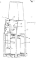
- Fig. 1 an emptying device 1 according to the invention is shown, in front of which a user is located and under which a barrel F to be emptied is arranged.
- the keg F contains, for example, powdered and / or granular substances which pose a potential hazard to the user and the environment when released. For this reason, it is necessary that this product is taken from the barrel F free of contamination.
- the emptying device 1 comprises an insulating device 2 and a container connection device 3 for connecting the drum F.
- the isolation device 2 is formed of an insulator having two openings 20 with glove engagements (not shown) attached thereto.
- the user A can insert his arms and hands through the openings 20 into the gloves and safely perform activities in an interior 23 of the isolation device 2 and the insulator.
- the isolation device 2 has a viewing window 24 so that the user A can observe his activities in the interior.
- the to be emptied barrel F is located in the in Fig. 1 shown state below the isolation device 2 so that it can be connected to a arranged on the bottom of the isolation device 2 container connection device 3.
- one or two film sacks are preferably provided inside the drum F, both of which surround the product and are each closed separately.
- the upper ends of these two film bags can be attached to the container connection device 3 so that there is no endangerment of the user by the product.
- the X direction shown corresponds to the depth direction of the isolation device, the Y direction shown in the width direction of the isolation device 2 and the Z direction of the height direction of the emptying device 1 according to the invention.
- the dimensions of the isolation device in the X and Y directions are preferably selected so that the User A all elements, in particular a located in the interior 23 conveyor line, can achieve good.
- the container connection device 3 is arranged on a lower side of the insulation device 2, so that the barrel F to be emptied can be brought into the vicinity or to the container connection device 3 by lifting.
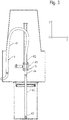
- Fig. 2 shows a sectional view of the in Fig. 1 according to the invention shown emptying device 1, wherein the cut was made to approximately half the depth of the insulating device 2 in the Y direction. Consequently, the in Fig. 2 shown view of the YZ plane and shows the interior 23 from the perspective of the user A.
- the container connection device 3 is formed from a ring 30, which circulates a through opening 21 leading into the isolation device 2, two recesses 31 which encircle the ring 30 being provided on an outer side of the ring 30 being provided.
- an inflatable seal 32 is provided, via which a clamping ring can be fixed or fixed.
- the user opens a lid of the barrel F in a first step and secures an upper end of a foil bag located in the barrel F on the inner recess 31 facing the underside of the insulating device 2, wherein a film residue, not shown, which is attached to the outer of the two recesses 31 and comes from a preceding emptying process is included.
- the attachment is preferably by means of an O-ring.
- the film bag fastened to the interior of the recesses 31 can now be opened by the user from the outside by removing a corresponding closure. Should the product located in barrel F be surrounded by an additional inner foil bag located in the foil bag, the foil bag secured to the interior of the two depressions 31 can be opened prior to its attachment.
- the film residue fastened to the outer of the depressions 31 is detached from the container connection device by the user by means of the glove inserts and disposed of within the insulation device, for example into a waste bag attached to the insulation device 2.
- the film bag fastened to the inner of the recesses 31 is then preferably offset to the outer of the recesses 31.
- the inner foil bag must be opened before it is emptied. This takes place in that the user engages in the glove inserts by means of the openings 20 provided in the insulating device 2 and opens the closure of the second inner film bag through the opening 21.
- the upper end of the inner foil bag is placed over the already mentioned clamping ring and fixed via a provided on the inside of the ring inflation seal 32.
- the barrel F is now in a state in which it can be emptied.
- a delivery line 4 which has a flexible delivery hose 41 and a rigid suction pipe 42.
- connection element 5 which has a line connection 51 arranged in the interior space 23 and an external connection 52 arranged on the outside of the insulation device 2.
- the connection element For example, is welded into the side wall 26 of the insulation device 2 in such a way that the line connection 51 immovable (firmly anchored, fixed) in the interior 23 of the insulation device 2 and the outer terminal 52 immovable (firmly anchored, fixed) on the outside of the isolation device 2 is located.
- connection element 5 can alternatively be fastened to the side wall 26 of the insulation device 2 in a different manner. Examples include non-positive, cohesive and positive fastenings that ensure a tight attachment of the connection element 5 on the side wall 26.
- connection 51 of the flexible delivery hose 41 of the delivery line 4 is fixed and extends in the height direction to an upper portion of the insulating device 2, where it is arcuate and is secured with its other end to the suction pipe 42.
- the suction pipe 42 extends in the direction of the opening 21 and ends shortly before the opening 21.
- the suction pipe has a delivery end 43 with an inlet opening.
- the delivery line 4 is located in the in Fig. 2 shown position in its initial position or the conveying end 43 is in its initial position.
- the delivery line 4 is fixed at the level of the connection between the flexible delivery hose 41 and the suction pipe 42 to a carriage 61 of a trained as a guide suspension 6.
- the carriage 61 engages with a rail 62 and is movable on the rail 62.
- the rail 62 is straight in the height direction, whereby the suction pipe 42 of the delivery line 4 in the height direction lowered through the opening 21 and the conveying end 43 can be brought into contact with the product located in the barrel F in touch.
- the delivery hose 41 Due to the flexibility of the delivery hose 41, the delivery hose 41 allows this movement and the lowering of the suction pipe 42 and follows the movement, wherein the end of the flexible delivery hose 41 corresponding to the line connection is attached immovably and fixedly to the line connection 51.
- the user can operate the motor 7 both for lowering and lifting the delivery line 4.
- the user can move the carriage 61 on the rail 62 in both directions (positive z-direction and negative z-direction) via the motor 7.
- a pneumatic conveyor not shown, for example, can be attached via a hose.
- the pneumatic conveying device generates a negative pressure through the outer connection 52 and the line connection 51 in the delivery line 4, which leads to a gas flow from the inner space 23 through the delivery line 4 and the connecting element 5 in the direction of the pneumatic delivery device.
- filter elements which allow gas flow into the inner space 23 may be provided on the insulating device 2.
- the suction pipe 42 comes with its the barrel F facing the conveyor end 43 in the vicinity or contact with the product. Due to the negative pressure generated by the pneumatic conveyor which is located in the barrel F product is sucked and enters through the present at the end of the conveyor 43 opening in the delivery line 4 a. The product flows through the delivery line 4 to the connection element 5, where it passes out of the isolation device 2 through the line connection 51 and the outer connection 52 and enters the hose extending to the delivery device.
- the user A lowers the suction pipe 42 by operating the motor 7 until the drum F is emptied.
- the state in which the suction pipe 42 and the conveying end 43 has reached the bottom of the barrel F or the carriage 61 is moved on the rail 62 maximum is in Fig. 3 shown.
- the delivery hose 41 is in the in Fig. 2 and 3 shown variant of the delivery line 4 indirectly connected via a very flexible connecting hose 44 with the suction pipe 42.
- the connecting hose is connected on the one hand to the carriage 61 with the delivery hose 41 and on the other hand attached to the suction tube.
- the flexible connection hose 44 is formed from a material which is more flexible than the delivery hose 41 guided by the suspension 6.
- the very flexible connection hose 44 is located in particular between the suction pipe 42 and the slide 61.
- the very flexible connection hose 44 ensures that the suction pipe 42 can be moved with little effort over the entire barrel cross section (xy plane).
- the motor 7 is only a preferred feature in this variant of the delivery line or its suspension 6.
- Fig. 4 shows at the same time two alternative, unclaimed suspensions to that with reference to Fig. 2 and 3 explained.
- the delivery hose 41 is in turn attached on one end to the line connection 51 and on the other hand to the suction pipe 42.
- the connecting tube 41 extends between the conduit connection 51 and the suction tube 42 via a roller 61 'of a first alternative suspension 6'.
- the roller 61 ' is itself attached via a spring mounting 62' on an upper side of the insulating device 2.
- the roller 61 ' rotates Fig. 4 in the clockwise direction, at the same time the spring bearing 62 'is tensioned. If the user releases the delivery line 4 after emptying the drum F, the restoring force of the suspension 62 'causes the suction pipe 42 to be pulled out of the drum F and returned to its original position. In this case, the roller 61 'rotates counterclockwise. At the in Fig.
- the variant of the delivery line shown can also be provided at the connection between the suction pipe 42 and the delivery line 41, the very flexible connection hose 44, which allows the user, for example with one hand, the delivery line 4 at the connection between the delivery hose 41 and flexible connection hose 44 holds and with the other hand, the suction pipe 42 moves over the cross section of the barrel F for sucking the product.
- Fig. 4 shows another alternative suspension 6 "for holding the delivery line 4 in the interior 23.
- the suspensions 6 'and 6" may be present either individually or in combination in the interior 23.
- the suspension 6 is a spring cable which has a wire cable 61" fastened to the conveyor line 4, which is rolled up or unwound from a winding roller 62 ", the user gripping the conveyor line 4 through the glove inserts, for example at the connection between the conveyor hose 41 and very flexible connection hose 44, and this exerts a force on the delivery line 4 for lowering the delivery end 43 of the suction tube 42, the wire rope 61 "from the winding roll 62" unrolled, wherein at the same time a restoring force generated by the winding roller 62 "occurs. If the user lets go of the delivery line 4 after emptying the drum F, the suction pipe 42 is returned to its starting position or the delivery end 43 to its original position.
- Fig. 4 shown suspensions for weight compensation.
- Fig. 5 shows a further variant of a arranged in the isolation device 2 delivery line 4 ', which in turn has a flexible delivery hose 41 which is attached at one end to the line connection 51 and with its other end to an extendable telescopic suction.
- this variant of the delivery line 4 no suspensions are shown, however, it is possible to use all the suspensions explained above also here.
- this variant is suitable for purely manual extraction of the product from the connected barrel F.
- the telescopic suction tube can be handled very easily due to its flexible length by a user who performs his activity through the glove inserts in the interior.
- the user adjusts a certain length of the telescopic suction pipe 42 'and starts then introduce the conveying end 43 'of the telescopic suction tube 42' in the connected barrel F and to suck the product contained therein.
- the user extends the Teleskopsaugrohr 42 'as required with decreasing filling height of the barrel F to be emptied until ultimately the telescopic suction tube 42' reaches a length that allows complete emptying of the barrel F.
- the state in which the telescopic suction tube 42 'has a length necessary for the complete emptying of the drum F is shown in FIG Fig. 6 shown.
- the telescopic suction tube 42 ' may preferably have 2, 3 or more sub-tubes for extending the entire telescopic intake 42'.
- FIG Fig. 7 A preferred variant of a suction pipe 42 'to be connected to the flexible delivery hose 41 is in FIG Fig. 7 shown.
- This suction pipe 42 ' includes an inner pipe 42'-1 and an outer pipe 42'-2, wherein the inner pipe 42'-1 passes through the outer pipe 42'-2.
- a space between the outer tube 42'-2 and the inner tube 42'-1 functions as a gas supply line, through which a gas to the inlet opening at the delivery end 43 of the suction pipe 42 'can be passed.
- the gas emerging from the gas supply line at the delivery end 43 is sucked into the inner tube 42 '-1 together with the product to be conveyed through the inlet opening located at the delivery end.
- the supplied gas is particularly advantageous for continuous production.
- FIG. 7 shown suction tube 42 'is particularly in the in Fig. 1 to 4 shown emptying device 1 according to the invention.
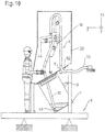
- Fig. 8 shows the emptying device 1 according to the invention, wherein the insulation device 2 is preferably modified.
- the bottom 27 of the isolation device 2 is not as in the Fig. 1 to 7 shown horizontally but runs in the in Fig. 8 shown xz plane obliquely so that a user can completely see through the provided on the insulating device 2 window 24 to be emptied barrel.
- the container connection device is arranged in such a way that a drum F connected as intended to it is tilted in the direction of the window 24 or the glove inserts. This has the particular advantage that the product contained in the drum F collects at a lower edge of the bottom area of the drum F and can be well extracted by the user by means of the suction pipe 42 here.
- the delivery line 4 may be one of the with reference to Fig. 1 to 7 have explained embodiments. Only the connection element 5 is in the in Fig. 8 shown variant of the delivery line 4 is formed so that the line connection 51 and the outer terminal 52 together in height direction rectilinear, and not as in the Fig. 1 to 7 the lead terminal 51 is bent in the interior space.
- Fig. 9 shows the in Fig. 8 shown emptying device 1, wherein the conveying line 4 by a preferred alternative, not claimed suspension 6 '''in the interior 23 of the insulating device 2 is supported.
- the suspension 6 ''' comprises a rocker arm 61'', which can be pivoted about a pivot axis 62''' extending in the Y-direction or width direction, wherein pivoting the rocker arm 61 '''a restoring moment about the pivot axis 62 '''occurs Fig. 9
- the user has almost completely emptied the drum F. If the user A lets go of the delivery line in this state, the restoring moment causes the delivery line or the delivery end 43 to be returned to their original position or returned.
- the pivot axis 62 '' 'of the rocker arm 61' '' is located at one end of the rocker arm 61 '' 'and, as mentioned, the pivot axis extends in the Y direction. That the rocker arm 61 '' 'pivots in the X-Z plane. In the first position of the rocker arm 61 '' 'are the delivery line 4 and the delivery end 43 in the corresponding starting position. When the user pulls on the delivery line 4, the rocker arm 61 '"moves to the second position.
- the flexible delivery hose 41 runs as in Fig. 9 shown on the rocker arm 61 '''and on the one hand to the line connection 51 and on the other hand attached to the suction pipe 42.
- the delivery line 4 can as needed as under Fig. 2 to 8 be designed described.
- a weighing device 8 may be provided, on which the emptying device 1 according to the invention is arranged together with the user.
- the connecting element 5 is firmly anchored as in the previous embodiments of the isolation device 2 and fixed immovably to the insulation device 2.
- the weight determination can be further improved by the behavior of the user himself. For example, if the user removes some of the product in barrel F and then pulls the delivery end 43 out of the product, the user A waits until the delivery line 4 located in the interior 23 has emptied to allow the product in the delivery line 4 does not distort the weight determination. The weight of the product taken up to the drum F up to this time can be easily determined by comparing the initial total weight with the total weight now present.
- Fig. 11 shows a variant of in Fig. 10
- the user in the in Fig. 11 variant shown not on the weighing device 8 but on a separately provided for the user pedestal is located.
- the user should determine the initial weight at a time when he does not have his arms in the gloves. This is because any force on the weighing device 8 is avoided by the user himself.
- the user grips the delivery line in the interior via the gloves and sucks a certain amount of the product contained in the barrel F from. He then transfers the delivery line 4 to its starting position, in which the delivery end 43 is not in the drawer to be emptied F, pulls the arms out of the gloves inserts and determined after complete emptying of the delivery line 4, the current weight of the entire emptying device 1. By comparison with the original / initial total weight, in turn, the weight of the withdrawn amount of the product can be determined.
- a vibrating device 9 may be mounted which vibrates the barrel F so that the product contained in the barrel F collects at the bottom edge of the barrel F.
Description
Die Erfindung betrifft eine Entleerungseinrichtung zur Entleerung eines ein Produkt enthaltenden Behälters, insbesondere eines Fasses.The invention relates to an emptying device for emptying a container containing a product, in particular a barrel.
Im Stand der Technik werden Behälter, insbesondere Fässer, durch Vorrichtungen entleert, bei denen Sauglanzen durch eine auf dem Fass angeordnete Platte oder einen auf dem Fass angeordneten Isolator hindurchgeführt werden. An der entsprechenden Sauglanze ist eine pneumatische Fördereinrichtung angeschlossen, die das in dem Fass vorhandene Produkt absaugt.In the prior art containers, especially barrels, emptied by devices in which suction lances are passed through an arranged on the barrel plate or arranged on the barrel insulator. At the corresponding suction lance a pneumatic conveyor is connected, which sucks the existing product in the barrel.
Die hierbei verwendeten Sauglanzen haben in Abhängigkeit von der Höhe der zu entleerenden Fässer eine bestimmten Länge und sind aus einem Metall ausgebildet, weshalb die Sauglanzen von einem Anwender nur unter einem nicht unerheblichen Kraftaufwand bei der Fassentleerung bewegt und gehandhabt werden können.The suction lances used in this case have a certain length depending on the height of the barrels to be emptied and are formed of a metal, which is why the suction lances can be moved and handled by a user only under a considerable effort in barrel emptying.
Aus dem Dokument
Weiterhin ist aus dem Dokument
Weiterer Stand der Technik findet sich in
Vor diesem Hintergrund ist es Aufgabe der Erfindung, eine Entleerungseinrichtung zur Entleerung eines ein Produkt enthaltenden Behälters, insbesondere eines Fasses, zu schaffen, die eine leichtere oder zumindest alternative Entleerung eines ein Produkt enthaltenden Behälters ermöglicht.Against this background, it is an object of the invention to provide an emptying device for emptying a container containing a product, in particular a barrel, which allows easier or at least alternative emptying of a container containing a product.
Diese Aufgabe wird mit einer Entleerungseinrichtung gemäß Anspruch 1 gelöst. Weitere bevorzugte Ausführungsformen sind Gegenstand der Unteransprüche.This object is achieved with an emptying device according to
Mit der erfindungsgemäßen Entleerungseinrichtung werden insbesondere Behälter entleert, die ein pulver- und/oder granulatförmiges Produkt enthalten, das beispielsweise eine potentielle Gefährdung eines Anwenders darstellt, die Umgebung potentiell verunreinigen würde und/oder einen zu bewahrenden Reinheitsgrad aufweist.With the emptying device according to the invention in particular containers are emptied, containing a powdery and / or granular product, for example, represents a potential hazard to a user, the environment would potentially contaminate and / or has to be preserved degree of purity.
Erfindungsgemäß umfasst eine Entleerungseinrichtung zur Entleerung eines ein Produkt enthaltenden Behälters, insbesondere eines Fasses, eine Isolationseinrichtung, die einen Innenraum festlegt bzw. einen solchen aufweist und Tätigkeiten eines Anwenders in dem Innenraum ohne Kontaminationsgefährdung des Anwenders zulässt.According to the invention, an emptying device for emptying a container containing a product, in particular a drum, comprises an insulating device which defines or has an interior space and permits activities of a user in the interior space without endangering the user's risk of contamination.
Eine solche Isolationseinrichtung ist ein Isolator mit Handschuheingriffen, über die der Anwender in dem Innenraum des Isolators Tätigkeiten durchführen kann. Dadurch, dass der Isolator Eingriffe für den Anwender aufweist, kommt dieser nicht direkt mit dem Innenraum des Isolators und damit mit einem in dem Innenraum vorhandenen Produkt in Berührung. Damit wird sichergestellt, dass keine Kontaminationsgefährdung des Anwenders besteht.Such an isolation device is an insulator with glove interventions, by means of which the user can carry out activities in the interior of the insulator. Due to the fact that the isolator has interventions for the user, the latter does not come into direct contact with the interior of the insulator and thus with a product present in the interior. This ensures that there is no risk of contamination for the user.
Weiterhin umfasst die erfindungsgemäße Entleerungseinrichtung eine Behälteranschlusseinrichtung zum derartigen Anschließen des Behälters an die Isolationseinrichtung, dass keine Kontaminationsgefährdung des Anwenders durch das Produkt besteht.Furthermore, the emptying device according to the invention comprises a container connection device for connecting the container to the insulation device such that there is no risk of contamination of the user by the product.
Bei einer solchen Behälteranschlusseinrichtung kann es sich beispielsweise um einen an einer in die Isolationseinrichtung führenden Öffnung vorgesehenen Ring handeln, an dem Vertiefungen ausgebildet und/oder eine Blähdichtung vorgesehen ist. Die Vertiefungen und/oder die Blähdichtung dienen zur Befestigung eines das Produkt in dem zu entleerenden Behälter umgebenden Foliensackes oder, wenn aus Sicherheitsgründen das Produkt von mehreren Foliensäcken umgeben ist, zur Befestigung aller dieser Foliensäcke.Such a container connection device may be, for example, a ring provided on an opening leading into the isolation device, on which recesses are formed and / or an inflatable seal is provided. The depressions and / or the inflatable seal serve to secure a foil bag surrounding the product in the container to be emptied or, if for safety reasons The product is surrounded by several foil sacks, for fixing all these foil sacks.
Die Behälteranschlusseinrichtung ist bevorzugt auf einer Unterseite der Isolationseinrichtung angeordnet, wobei der zu entleerende Behälter bzw. ein Fass beispielsweise durch Anheben an die Behälteranschlusseinrichtung herangeführt werden kann.The container connection device is preferably arranged on a lower side of the isolation device, wherein the container to be emptied or a keg can be introduced, for example, by lifting to the container connection device.
Beispielsweise wird bei einem Fass, in dem das Produkt aus Sicherheitsgründen von zwei Foliensäcken umgeben ist, der äußere Foliensack auf der Außenseite des an der Öffnung vorgesehenen Ringes an einer inneren zweier Vertiefungen über einen O-Ring derart befestigt, dass ein Folienrest, der an einer äußeren der zwei Vertiefungen befestigt ist und von einem vorhergehenden Entleerungsvorgang stammt, eingeschlossen wird. Anschließend wird über die Isolationseinrichtung, die Tätigkeiten des Anwenders in ihrem Innenraum ohne Kontaminationsgefährdung des Anwenders zulässt, der Folienrest von der äußeren Vertiefung durch den Innenraum der Isolationseinrichtung hindurch entfernt. Der zweite bislang noch verschlossene und das Produkt in dem Fass umgebende innere Foliensack ist nach Entfernen des Folienrestes über die Isolationseinrichtung zugänglich und kann über die Handschuheinsätze geöffnet werden. Der geöffnete innere Foliensack kann nunmehr beispielsweise über einen Klemmring gelegt und an der Öffnung durch Expansion der Blähdichtung befestigt bzw. fixiert werden.For example, in a barrel in which the product is surrounded by two film bags for safety reasons, the outer film bag on the outside of the ring provided on the opening at an inner two wells via an O-ring is fixed such that a film residue, which at one outer of the two recesses is fixed and comes from a previous emptying process is included. Subsequently, the foil remainder is removed from the outer depression through the interior of the isolation device via the insulation device, which allows the user's activities in their interior without endangering the user. The second still closed and surrounding the product in the barrel inner foil bag is accessible after removal of the film residue on the isolation device and can be opened on the gloves inserts. The opened inner foil bag can now for example be placed over a clamping ring and fastened or fixed to the opening by expansion of the inflatable seal.
Das aus dem Fass zu entnehmende Produkt ist hiernach durch den Innenraum der Isolationseinrichtung hindurch zugänglich, wobei, wie erläutert, das Anschließen des Behälters zu keiner Kontaminationsgefährdung des Anwenders durch das Produkt geführt hat.The product to be taken out of the drum is thereafter accessible through the interior of the isolation device, wherein, as explained, the connection of the container has not led to a risk of contamination of the user by the product.
In Abhängigkeit davon, welche Art von Behälter an die Isolationseinrichtung anzuschließen ist, kann die Behälteranschlusseinrichtung entsprechend ausgebildet sein. Beispielsweise kann die Entleerungseinrichtung so ausgestaltet sein, dass die Behälteranschlusseinrichtung austauschbar ist, insbesondere zur Anpassung an unterschiedliche Fassdurchmesser.Depending on which type of container is to be connected to the isolation device, the container connection device can be designed accordingly. For example, the emptying device can be designed such that the container connection device is interchangeable, especially for adaptation to different drum diameter.
Insbesondere ist die Behälteranschlusseinrichtung zum kontaminationsfreien Anschließen eines Fasses, das einen oder zwei das Produkt in dem Fass umgebende Foliensäcke aufweist, eingerichtet. Zum Anschließen eines Fasses kann die Behälteranschlusseinrichtung bevorzugt eine auf einer Außenseite der Isolationseinrichtung vorgesehene Dichtung aufweisen, gegen die das zu entleerende Fass bzw. dessen oberer Rand gedrückt werden kann.In particular, the container connection device is designed for the contamination-free connection of a drum which has one or two film sacks surrounding the product in the drum. For connecting a drum, the container connection device may preferably have a seal provided on an outer side of the insulation device, against which the drum or its upper edge to be emptied can be pressed.
Weiterhin umfasst die erfindungsgemäße Entleerungseinrichtung eine in dem Innenraum angeordnete Förderleitung, die mit einem Anschlussende an einem in dem Innenraum angeordneten Leitungsanschluss zum Ausleiten des Produktes aus der Isolationseinrichtung befestigt ist, und zur Entleerung des Behälters, insbesondere des Fasses, derart bewegt werden kann, dass sich bei angeschlossenem Behälter ein Förderende der Förderleitung in dem Behälter befindet.Furthermore, the emptying device according to the invention comprises a delivery line arranged in the interior, which is fastened with a connection end to a line connection arranged in the interior for discharging the product from the isolation device, and for emptying the container, in particular of the barrel, can be moved such that when the container is connected, a delivery end of the delivery line is located in the container.
Der Leitungsanschluss kann beispielsweise durch ein Anschlusselement, das in eine Seitenwand der Isolationseinrichtung eingeschweißt ist, ausgebildet sein und von der Seitenwand in den Innenraum vorstehen. An dem Leitungsanschluss wird die Förderleitung beispielsweise durch eine Klemmverbindung, die einen Flansch des Leitungsanschlusses mit einem Flansch der Förderleitung über eine Klammer verbindet, hergestellt. Auf einer Außenseite der Isolationseinrichtung ist ein mit dem Leitungsanschluss in Verbindung stehender Außenanschluss vorgesehen, an dem eine pneumatische Fördereinrichtung befestigt wird. Durch den Leitungsanschluss und den Außenanschluss hindurch kann das Produkt aus der Isolationseinrichtung herausgeleitet werden.The line connection may be formed, for example, by a connection element, which is welded into a side wall of the insulation device, and projecting from the side wall into the interior space. At the line connection, the delivery line is produced, for example, by a clamp connection which connects a flange of the line connection with a flange of the delivery line via a clamp. On an outer side of the isolation device, an external connection communicating with the line connection is provided, to which a pneumatic conveying device is fastened. Through the conduit connection and the external connection, the product can be led out of the isolation device.
Insbesondere dadurch, dass kein rigides unter Umständen sehr langes und schweres Saugrohr durch eine in der Isolationseinrichtung vorgesehene Öffnung geführt werden muss, sondern sich erfindungsgemäß die Förderleitung von dem in dem Innenraum angeordneten, feststehenden (unbeweglichen bzw. fest verankertem) Leitungsanschluss erstreckt und sich das Förderende in den zu entleerenden Behälter bewegen lässt wird, ist die Förderleitung und damit die Entleerung des Behälters leichter handzuhaben. Allgemein ausgedrückt befinden sich die bewegten Teile in dem Innenraum der Isolationseinrichtung.In particular, by the fact that no rigid possibly very long and heavy suction pipe must be performed by an opening provided in the isolation device, but according to the invention the delivery line from the arranged in the interior, fixed (immovable or firmly anchored) line connection extends and the delivery end is moved into the container to be emptied, the delivery line and thus the emptying of the container is easier to handle. Generally speaking, the moving parts are located in the interior of the isolation device.
Die Entleerung des Behälters ist insgesamt weniger anstrengend.The emptying of the container is less strenuous overall.
Bevorzugt ist die Förderleitung durch einen flexiblen Förderschlauch und ein Teleskopsaugrohr ausgebildet.Preferably, the delivery line is formed by a flexible delivery hose and a telescopic suction tube.
In dem Fall, dass die Förderleitung ausschließlich aus einem flexiblen Förderschlauch ausgebildet ist, kann der Anwender diesen leicht bzw. dessen Förderende in den Behälter zur Entleerung bzw. zur Entnahme des Produktes bewegen.In the event that the delivery line is formed exclusively of a flexible delivery hose, the user can easily move this or its end in the container for emptying or for removal of the product.
In dem anderen nicht erfindungsgemäßen Fall, dass die Förderleitung ausschließlich aus einem Teleskopsaugrohr ausgebildet ist, kann der Anwender das Teleskopsaugrohr ausfahren, damit das Förderende des Teleskopsaugrohres das sich in dem zu entleerenden Behälter befindende Produkt erreicht.In the other not inventive case, that the delivery line is formed exclusively of a telescopic suction, the user can extend the telescopic suction tube, so that the conveying end of the telescopic suction reaches the product located in the container to be emptied.
Zur Sicherstellung, dass mit dem Teleskopsaugrohr das gesamte sich in dem Behälter befindende Produkt entnommen werden kann, ist es beispielsweise möglich, die Behälteranschlusseinrichtung so auszugestalten, dass sich der zu entleerende Behälter - im angeschlossenen Zustand - senkrecht zu einer Längsachse des Teleskopsaugrohres bewegen lässt. Diese Bewegung lässt sich bevorzugt durch eine derartige Drehung des Behälters erreichen, dass eine Längsachse des zu entleerenden Behälters/Fasses sich um die Längsachse des Teleskopsaugrohres dreht.In order to ensure that the entire product located in the container can be removed with the telescopic suction tube, it is possible, for example, to design the container connection device in such a way that the container to be emptied can be moved perpendicular to a longitudinal axis of the telescope suction tube when connected. This movement can preferably be achieved by such a rotation of the container that a longitudinal axis of the container / drum to be emptied rotates about the longitudinal axis of the telescopic suction tube.
Darüber hinaus kann die Förderleitung aus einer Kombination aus einem flexiblen Förderschlauch und einem Saugrohr/Teleskopsaugrohr ausgebildet sein.In addition, the delivery line may be formed from a combination of a flexible delivery hose and a suction tube / Teleskopsaugrohr.
Durch die Verwendung eines flexiblen Förderschlauches wird insbesondere eine Gewichtsreduktion der Förderleitung erzielt.By using a flexible delivery hose in particular a weight reduction of the delivery line is achieved.
Bevorzugt ist das Förderende der Förderleitung durch ein Saugrohr oder Teleskopsaugrohr ausgebildet, wobei das Saugrohr oder Teleskopsaugrohr über den flexiblen Förderschlauch an dem Leitungsanschluss befestigt ist.Preferably, the delivery end of the delivery line is formed by a suction tube or telescopic suction tube, wherein the suction tube or telescopic suction tube is attached via the flexible delivery hose to the line connection.
Hierdurch lässt sich das Saugrohr oder Teleskopsaugrohr leicht in den das Produkt enthaltenden Behälter führen und das Produkt entnehmen.This allows the suction tube or Teleskopsaugrohr easily lead into the container containing the product and remove the product.
Die Förderleitung ist in dem Innenraum an einer Aufhängung befestigt, die die Bewegung des Förderendes in den Behälter zulässt und die Förderleitung während der Bewegung haltert.The delivery line is secured in the interior to a suspension that allows movement of the delivery end into the container and supports the delivery line during movement.
Hierdurch wird der Anwender, der die Tätigkeit in dem Innenraum der Isolationseinrichtung - nämlich das Bewegen der Förderleitung - beispielsweise über die Handschuheinsätze durchführt, unterstützt, weshalb die Entleerung des Behälters bzw. die Entnahme des Produktes erleichtert wird.As a result, the user, who performs the activity in the interior of the isolation device - namely moving the conveyor line - for example, via the gloves inserts, supported, so the emptying of the container or the removal of the product is facilitated.
Die Aufhängung weist eine Führungsschiene und einen auf der Führungsschiene verfahrbaren Schlitten auf, wobei die Förderleitung an dem Schlitten derart befestigt ist, dass durch Verfahren des Schlittens das Förderende entweder in den oder aus dem Behälter bewegt wird.The suspension has a guide rail and a slide movable on the guide rail, wherein the conveyor line is fixed to the carriage such that by moving the carriage the conveying end is moved either in or out of the container.
Insbesondere ist hierbei bevorzugt, dass die Führungsschiene geradlinig ist, ergo die Aufhängung eine Linearführung ist. Alternativ kann die Führungsschiene einen bogenförmigen Verlauf haben, derart, dass das Förderende durch Verfahren des Schlittens eine bogenförmige Bewegung beschreibt.In particular, it is preferred that the guide rail is rectilinear, ergo the suspension is a linear guide. Alternatively, the guide rail may have an arcuate course, such that the conveyor end describes an arcuate movement by moving the carriage.
Je nachdem welche Größen die zu entleerenden Behälter/Fässer aufweisen, kann die Förderleitung zur Bewegung des Förderendes in den/aus dem Behälter durch eine Antriebseinheit, wie beispielsweise einen Motor, bewegt/verstellt werden. Hierbei kann die Antriebseinheit beispielsweise eine manuelle Tätigkeit des Anwenders unterstützen oder auch das Bewegen der Förderleitung vollständig übernehmen.Depending on the sizes of the containers / drums to be emptied, the conveyor line for moving the conveyor end into / out of the container can be moved / adjusted by a drive unit, such as a motor. Here, the drive unit For example, support a manual activity of the user or completely take over the moving of the support line.
Eine Antriebseinheit, beispielsweise ein Motor, kann insbesondere an dem Schlitten montiert sein, die/der zum Verfahren des Schlittens betätigt werden kann. Die Antriebseinheit/der Motor kann insbesondere so ausgestaltet sein, dass er eine FDA-Zulassung (Food and Drug Administration) und EX-Zulassung (Explosionsschutz-Zulassung) aufweist.A drive unit, for example a motor, can in particular be mounted on the carriage, which can be actuated for moving the carriage. In particular, the drive unit / motor can be designed such that it has FDA approval (Food and Drug Administration) and EX approval (explosion protection approval).
Die Antriebseinheit(en)/die Motor(en), die im Vorhergehenden erwähnt wurden, können beispielsweise pneumatisch betriebene oder elektrisch betriebene Motoren sein.The drive unit (s) mentioned above may, for example, be pneumatically driven or electrically driven motors.
Bevorzugt ist das Förderende durch ein Saugrohr ausgebildet, das über den flexiblen Förderschlauch an dem Leitungsanschluss befestigt ist. Der Förderschlauch ist mit einem dem Anschlussende entsprechenden Ende an dem Leitungsanschluss und mit einem anderen Ende an dem Schlitten befestigt, wobei das Saugrohr über einen Verbindungsschlauch, der flexibler ist als der Förderschlauch, an dem Schlitten und/oder dem Förderschlauch befestigt ist.Preferably, the delivery end is formed by a suction tube which is attached via the flexible delivery hose to the line connection. The delivery hose is attached to the pipe connection at an end corresponding to the connection end and to the carriage at another end, the suction pipe being attached to the carriage and / or the delivery hose via a connection hose that is more flexible than the delivery hose.
Hierdurch lässt sich die Förderleitung über den Schlitten leicht verfahren und gleichzeitig das Saugrohr aufgrund des sehr flexiblen Verbindungsschlauches innerhalb des zu entleerenden Behälters über den Querschnitt des zu entleerenden Behälter/Fasses bewegen.As a result, the conveying line can be easily moved over the carriage and at the same time move the suction tube due to the very flexible connection hose within the container to be emptied over the cross section of the container / barrel to be emptied.
Weiterhin bevorzugt kann die Förderleitung einen flexiblen Förderschlauch aufweisen, der mit einem dem Anschlussende entsprechenden Ende an dem Leitungsanschluss befestigt ist. Die Aufhängung kann gemäß einem nicht erfindungsgemäßen Vergleichsbeispiel eine mittels einer Federlagerung gelagerte Rolle sein, über die der Förderschlauch verläuft, wobei die Aufhängung während der Bewegung des Förderendes in den/aus dem Behälter den Förderschlauch durch eine Kombination aus einer Drehung der Rolle und einer Federwirkung der Federlagerung haltert.Further preferably, the delivery line may comprise a flexible delivery hose which is attached to the conduit connection with an end corresponding to the connection end. According to a comparative example not according to the invention, the suspension can be a roller mounted by means of a spring bearing over which the delivery hose runs, the suspension being moved during the movement of the delivery end into / out of the container by a combination of a rotation of the roller and a spring action of the conveyor Spring bearing holds.
Alternativ kann die Aufhängung gemäß einem nicht erfindungsgemäßen Vergleichsbeispiel ein pneumatisch betriebener Zylinder sein, an dem die Förderleitung befestigt ist und der sich pneumatisch betrieben ein-/ausfahren lässt, um das Förderende in den/aus dem Behälter zu bewegen. Bevorzugt ist das Förderende durch ein Saugrohr ausgebildet, das über einen flexiblen Förderschlauch an dem Leitungsanschluss befestigt ist. Insbesondere ist auch in diesem Fall der Förderschlauch mit einem dem Anschlussende entsprechenden Ende an dem Leitungsanschluss und mit einem anderen Ende an dem pneumatisch betriebenen Zylinder befestigt, wobei das Saugrohr über einen Verbindungsschlauch, der flexibler ist als der Förderschlauch, an dem Zylinder und/oder dem Förderschlauch befestigt ist.Alternatively, according to a comparative example not according to the invention, the suspension may be a pneumatically operated cylinder to which the delivery line is attached and which can be pneumatically driven in / out to move the delivery end into / out of the container. Preferably, the delivery end is formed by a suction tube, which is fastened via a flexible delivery hose to the line connection. In particular, also in this case the delivery hose is attached to the pipe connection with an end corresponding to the connection end and to the pneumatically operated cylinder at another end, the suction pipe being connected to the cylinder and / or the hose via a connection hose which is more flexible than the delivery hose Delivery hose is attached.
Alternativ kann die Aufhängung gemäß einem nicht erfindungsgemäßen Vergleichsbeispiel ein Federzug sein, der die Förderleitung während der Bewegung des Förderendes in den/aus dem Behälter durch eine Federwirkung des Federzuges haltert.Alternatively, according to a comparative example not according to the invention, the suspension can be a spring pull which supports the delivery line during the movement of the delivery end into / out of the container by a spring action of the spring pull.
Weiterhin bevorzugt weist die Förderleitung einen flexiblen Förderschlauch auf, der mit einem dem Leitungsanschluss entsprechenden Ende an dem Leitungsanschluss befestigt ist. Die Aufhängung ist gemäß einem nicht erfindungsgemäßen Vergleichsbeispiel bevorzugt ein Kipphebel, über den der Förderschlauch verläuft und der während der Bewegung des Förderendes in den/aus dem Behälter den Förderschlauch durch eine Kipp- bzw. Schwenkbewegung haltert.Further preferably, the delivery line to a flexible delivery hose, which is fixed with an end corresponding to the line connection to the line connection. According to a comparative example not according to the invention, the suspension is preferably a rocker arm, over which the delivery hose extends and which, during the movement of the delivery end into / out of the container, holds the delivery hose by means of a tilting or pivoting movement.
Durch die im Vorhergehenden beschriebenen Aufhängungen wird insbesondere eine Gewichtskompensation erreicht, die eine sehr leichte Handhabung der Förderleitung und damit eine sehr leichte Entleerung des Behälters ermöglichen.By the suspensions described above in particular a weight compensation is achieved, which allow a very easy handling of the delivery line and thus a very easy emptying of the container.
Insbesondere ist die Aufhängung bevorzugt derart eingerichtet, dass sie das Förderende auf eine Ausgangsposition zurückstellt, wenn keine Kraft von dem Anwender beispielsweise über die Handschuheinsätze auf die Förderleitung ausgeübt wird. In den oben genannten nicht erfindungsgemäßen Vergleichsbeispielen kann dies beispielsweise durch eine Dimensionierung der Federwirkung der die Rolle lagernden Federlagerung oder des Federzuges erreicht werden.In particular, the suspension is preferably arranged such that it returns the conveyor end to a starting position when no force is exerted by the user, for example via the gloves inserts on the delivery line. In the above-mentioned comparative examples not according to the invention This can be achieved, for example, by dimensioning the spring action of the roll bearing spring bearing or the spring tension.
Bevorzugt ist das Förderende durch ein Teleskopsaugrohr ausgebildet, das in Abhängigkeit von einem Füllstand des Behälters verlängert und/oder verkürzt werden kann. Hierdurch kann die Bauhöhe der erfindungsgemäßen Entleerungseinrichtung verringert werden.Preferably, the conveyor end is formed by a telescopic suction tube, which can be extended and / or shortened depending on a level of the container. As a result, the overall height of the emptying device according to the invention can be reduced.
Bevorzugt ist das Förderende durch ein Saugrohr oder Teleskopsaugrohr ausgebildet, wobei das Saugrohr oder Teleskopsaugrohr eine Gaszufuhrleitung aufweist, über die ein Gas an eine Eintrittsöffnung an dem Förderende, durch die hindurch das Produkt in die Förderleitung bestimmungsgemäß eintritt, geleitet werden kann.The delivery end is preferably formed by a suction tube or telescopic suction tube, wherein the suction tube or telescope suction tube has a gas supply line, via which a gas can be passed to an inlet opening at the delivery end, through which the product enters the delivery line as intended.
Bevorzugt ist die Gaszufuhrleitung durch einen Zwischenraum zwischen einem Außenrohr des Saugrohres und einem in dem Außenrohr verlaufenden Innenrohr des Saugrohres ausgebildet.Preferably, the gas supply line is formed by a gap between an outer tube of the suction tube and an inner tube extending in the outer tube of the suction tube.
Durch die Zuführung des Gases kann in dem Fall einer pneumatischen Förderung bzw. einem Absaugen des aus dem Behälter zu entnehmenden Produktes eine kontinuierliche pneumatische Förderung sichergestellt werden.By supplying the gas, in the case of a pneumatic delivery or a suction of the product to be removed from the container, a continuous pneumatic delivery can be ensured.
Die Entleerungseinrichtung umfasst den bereits erläuterten mit dem Leitungsanschluss in Verbindung stehenden Außenanschluss, an dem bestimmungsgemäß eine pneumatische Fördereinrichtung anschließbar ist und eine Wägeeinrichtung zur Gewichtsbestimmung des Produktes, wobei die Wägeeinrichtung derart angeordnet ist, dass bei bestimmungsgemäßer Verwendung der Entleerungseinrichtung sich die Isolationseinrichtung und der Behälter auf der Wägeeinrichtung befinden.The emptying device comprises the already described connected to the line connection in connection external connection to the intended use of a pneumatic conveyor is connected and a weighing device for determining the weight of the product, wherein the weighing device is arranged such that when properly using the emptying the isolation device and the container the weighing device are located.
Vorteilhaft ist insbesondere, dass der Anschluss der pneumatischen Fördereinrichtung über den feststehenden (unbeweglichen, fest verankerten) Außenschluss erfolgt. Das heißt, da kein Saugrohr von außen durch eine in die Isolationseinrichtung führende Öffnung und durch den Innenraum hindurch in den Behälter geführt werden muss, werden keine von außen wirkenden Kräfte (bis auf die vernachlässigbare Gewichtskraft eines von dem Außenanschluss zu der pneumatischen Fördereinrichtung verlaufenden Außenschiauches) auf die Wägeeinrichtung ausgeübt und damit verfälschte Gewichtsbestimmungen vermieden. Die Wägeeinrichtung ermittelt bevorzugt das Gewicht des geförderten bzw. entnommenen Produktes durch Differenzbildung des anfänglich gemessenen Gesamtgewichtes und des nach Entnahme des Produktes gemessenen Gesamtgewichtes.It is particularly advantageous that the connection of the pneumatic conveyor via the fixed (immovable, firmly anchored) outer closure takes place. That is, since no suction pipe from the outside through an opening in the insulation device and through the interior must be guided into the container, no externally acting forces (except for the negligible weight of a running from the outer terminal to the pneumatic conveyor Außenschiauches) exerted on the weighing device and thus falsified weight determinations avoided. The weighing device preferably determines the weight of the conveyed or taken product by subtraction of the initially measured total weight and the total weight measured after removal of the product.
Weiterhin bevorzugt ist die Wägeeinrichtung derart angeordnet und ausgestaltet, dass bei bestimmungsgemäßer Verwendung der Entleerungseinrichtung sich auch der Anwender auf der Wägeeinrichtung befindet.Further preferably, the weighing device is arranged and configured such that, when the emptying device is used as intended, the user is also located on the weighing device.
Hierdurch wird noch besser verhindert, dass externe Kräfte auf die Wägeeinrichtung während der Entleerung des Behälters bzw. der Entnahme des Produktes wirken und zu einer verfälschten Gewichtsbestimmung führen, weil sich der Anwender selbst auf der Wägeeinrichtung befindet und Tätigkeiten des Anwenders zu keiner Kraftausübung auf die Wägeeinrichtung führen.This even better prevents external forces acting on the weighing device during emptying of the container or the removal of the product and lead to a falsified weight determination, because the user himself is on the weighing device and activities of the user to no force on the weighing device to lead.
Zusätzlich kann eine Erhöhung der Genauigkeit der Gewichtsbestimmung durch das Verhalten des Anwenders selbst erzielt werden. Zieht beispielsweise der Anwender das Förderende der Förderleitung aus dem sich in dem Behälter befindenden Produkt und wartet darauf, bis das sich in der Förderleitung befindende Produkt vollständig durch den Außenanschluss hindurch abgesaugt bzw. gefördert wurde, kann eine sehr genaue Gewichtsbestimmung der entnommenen Produktmenge aus dem anfänglich gemessenen Gesamtgewicht und dem nach der pneumatischen Förderung gemessenen Gesamtgewicht ermittelt werden.In addition, an increase in the accuracy of the weight determination can be achieved by the behavior of the user himself. For example, if the user pulls the delivery end of the delivery line out of the product in the container and waits for the product located in the delivery line to be completely aspirated through the external connection, a very accurate determination of the weight of the withdrawn amount of product can be made measured total weight and measured according to the pneumatic conveying total weight.
Bevorzugt umfasst die Isolationseinrichtung ein Sichtfenster, durch das der Anwender den Innenraum überblicken kann, wobei die Behälteranschlusseinrichtung derart schräg angeordnet ist, dass der Anwender bei angeschlossenem Behälter/Fass einen Innenraum des Behälters/Fasses durch das Sichtfenster und den Innenraum hindurch vollständig einsehen kann.Preferably, the isolation device comprises a viewing window through which the user can overlook the interior, wherein the Container connection device is arranged obliquely so that the user can fully view an interior of the container / barrel through the viewing window and the interior when connected container / barrel.
Hierdurch wird erreicht, dass zum einen sich das in dem Behälter befindende Produkt an einem Rand im Bodenbereich des Behälters sammelt und zum anderen der Anwender alle sich in dem Behälter befindenden Reste gut sehen kann.This ensures that, on the one hand, the product located in the container collects at one edge in the bottom region of the container and, on the other hand, the user can easily see all the residues located in the container.
Bevorzugt weist die erfindungsgemäße Entleerungseinrichtung noch eine Vibrationseinheit auf, die eine Vibration des Behälters/Fasses erzeugt. Durch diese Vibration werden an verschiedenen Stellen haftende Reste des zu entnehmenden Produktes gelöst und insbesondere in dem Fall des Schrägstehens des Behälters an einem Rand im Bodenbereich des Behälters gesammelt.Preferably, the emptying device according to the invention also has a vibration unit, which generates a vibration of the container / barrel. By this vibration adhering residues of the product to be removed are dissolved at various points and collected in particular in the case of skewing of the container at an edge in the bottom region of the container.
Die Isolationseinrichtung ist bevorzugt aus einem Metall oder einem Kunststoff ausgebildet. Gleiches gilt für das Saugrohr der Förderleitung, wobei dieses allgemein so konstruiert ist, dass es eine für eine pneumatische Förderung notwendige Stabilität aufweist aber ein möglichst geringes Eigengewicht aufweist.The isolation device is preferably formed from a metal or a plastic. The same applies to the intake manifold of the delivery line, which is generally constructed so that it has a stability necessary for a pneumatic conveying but has the lowest possible weight.
Der flexible Förderschlauch kann beispielsweise aus einem Kunststoff mit einer Spiralverstärkung oder auch aus einem Metall gebildet sein.The flexible delivery hose can for example be formed from a plastic with a spiral reinforcement or also from a metal.
Die Isolationseinrichtung ist insbesondere so dimensioniert, dass der Anwender alle Bereiche des Innenraumes, insbesondere die Förderleitung, den Schlitten und das Saugrohr, gut erreichen kann.The isolation device is particularly dimensioned so that the user can easily reach all areas of the interior, in particular the delivery line, the carriage and the suction tube.
Die erfindungsgemäße Entleerungseinrichtung wird insbesondere für die Entleerung von Behältern/Fässer eingesetzt, in denen das Produkt in Form eines Pulvers oder Granulats vorliegt.The emptying device according to the invention is used in particular for the emptying of containers / barrels in which the product is in the form of a powder or granules.
Unter Bezug auf die beigefügten Figuren werden nunmehr bevorzugte Ausführungsformen der erfindungsgemäßen Entleerungseinrichtung erläutert.
-
Fig. 1 zeigt die erfindungsgemäße Entleerungseinrichtung, wobei ein Anwender sich vor einer Handschuheingriffe aufweisenden Isolationseinrichtung befindet und ein zu entleerendes Fass unterhalb der Isolationseinrichtung und einer Behälteranschlusseinrichtung angeordnet ist. -
Fig. 2 zeigt einen Schnitt der erfindungsgemäßen Entleerungseinrichtung ausFig. 1 , wobei eine Förderleitung sich in ihrer Grundstellung und ein entsprechendes Förderende in seiner Ausgangsposition befindet. -
Fig. 3 zeigt die inFig. 2 gezeigte erfindungsgemäße Entleerungseinrichtung, wobei die Förderleitung bzw. das entsprechende Förderende sich in seinem maximal in das zu entleerende Fass verfahrbaren Zustand befindet. -
Fig. 4 zeigt die Entleerungseinrichtung, wobei schematisch zwei alternative, nicht erfindungsgemäße Aufhängungen für die Förderleitung gezeigt sind. -
Fig. 5 zeigt eine weitere Variante einer in dem Innenraum der Isolationseinrichtung angeordneten Förderleitung. -
Fig. 6 zeigt die erfindungsgemäße Entleerungseinrichtung ausFig. 5 , wobei das inFig. 5 gezeigte Teleskopsaugrohr sich in seinem maximal ausgefahrenen Zustand befindet und in das zu entleerende Fass bewegt ist. -
Fig. 7 zeigt eine bevorzugte Ausgestaltung eines Saugrohres, das bei der erfindungsgemäßen Entleerungseinrichtung Anwendung finden kann. -
Fig. 8 zeigt eine bevorzugte Ausgestaltung einer Isolationseinrichtung der erfindungsgemäßen Entleerungseinrichtung, wobei eine Seite der Isolationseinrichtung, an der sich die Behälteranschlusseinrichtung befindet, derart schräg verläuft, dass ein Anwender den Innenraum des zu entleerenden Fasses vollständig einsehen kann. -
Fig. 9 zeigt die Entleerungseinrichtung ausFig. 8 , bei der eine weitere bevorzugte alternative, nicht erfindungsgemäße Aufhängung der Förderleitung gezeigt ist. -
Fig. 10 zeigt die erfindungsgemäße Entleerungseinrichtung ausFig. 9 , bei der sich die gesamte erfindungsgemäße Entleerungseinrichtung zusammen mit dem Anwender auf einer Wägeeinrichtung befindet. -
Fig. 11 zeigt eine bevorzugte Abwandlung der Wägeeinrichtung, wobei diese mit der ausFig. 9 bis auf den Unterschied, dass sich der Anwender nicht auf der Wägeeinrichtung befindet, identisch ist.
-
Fig. 1 shows the emptying device according to the invention, wherein a user is located in front of a glove-engaging insulation device and to be emptied barrel below the isolation device and a container connection device is arranged. -
Fig. 2 shows a section of the emptying device according to the inventionFig. 1 , wherein a conveyor line is in its normal position and a corresponding end of delivery in its starting position. -
Fig. 3 shows the inFig. 2 shown emptying device according to the invention, wherein the delivery line or the corresponding end of delivery is in its maximum in the drawer to be emptied state. -
Fig. 4 shows the emptying device, whereby schematically two alternative, non-inventive suspensions for the delivery line are shown. -
Fig. 5 shows a further variant of a arranged in the interior of the isolation conveyor line. -
Fig. 6 shows the emptying device according to the inventionFig. 5 , where inFig. 5 shown telescopic suction tube is in its maximum extended state and is moved into the barrel to be emptied. -
Fig. 7 shows a preferred embodiment of a suction tube, which may find application in the emptying device according to the invention. -
Fig. 8 shows a preferred embodiment of an isolation device of the emptying device according to the invention, wherein one side of the insulation device, on which the container connection device is located, runs obliquely so that a user can completely see the interior of the barrel to be emptied. -
Fig. 9 shows the emptying deviceFig. 8 in which a further preferred alternative, non-inventive suspension of the delivery line is shown. -
Fig. 10 shows the emptying device according to the inventionFig. 9 in which the entire emptying device according to the invention is located on a weighing device together with the user. -
Fig. 11 shows a preferred modification of the weighing device, which with theFig. 9 except for the difference that the user is not on the weighing device is identical.
In
Hierfür umfasst die erfindungsgemäße Entleerungseinrichtung 1 eine Isolationseinrichtung 2 und eine Behälteranschlusseinrichtung 3 zum Anschließen des Fasses F.For this purpose, the
Die Isolationseinrichtung 2 ist aus einem Isolator ausgebildet, der zwei Öffnungen 20 mit daran befestigten Handschuheingriffen (nicht gezeigt) aufweist. Der Anwender A kann durch die Öffnungen 20 hindurch seine Arme und Hände in die Handschuheingriffe einführen und gefahrlos Tätigkeiten in einem Innenraum 23 der Isolationseinrichtung 2 bzw. des Isolators durchführen.The
Bevorzugt weist die Isolationseinrichtung 2 ein Sichtfenster 24 auf, damit der Anwender A seine Tätigkeiten in dem Innenraum beobachten kann.Preferably, the
Das zu entleerende Fass F befindet sich in dem in
Bei potentiell eine Gefährdung darstellenden Produkten sind bevorzugt ein oder zwei Foliensäcke innerhalb des Fasses F vorgesehen, die beide das Produkt umgeben und jeweils separat verschlossen sind.In the case of potentially endangering products, one or two film sacks are preferably provided inside the drum F, both of which surround the product and are each closed separately.
Wie im Folgenden noch erläutert werden wird, können die oberen Enden dieser beiden Foliensäcke an der Behälteranschlusseinrichtung 3 so befestigt werden, dass keine Gefährdung des Anwenders durch das Produkt besteht.As will be explained below, the upper ends of these two film bags can be attached to the
Die in
Wie in
Auf der Unterseite der Isolationseinrichtung 2 ist die erwähnte Behälteranschlusseinrichtung 3 gezeigt. Die Behälteranschlusseinrichtung 3 ist aus einem Ring 30 ausgebildet, der eine in die Isolationseinrichtung 2 führende Durchgangsöffnung 21 umläuft, wobei auf einer Außenseite des Ringes 30 zwei den Ring 30 vollständig umlaufende Vertiefungen 31 vorgesehen sind. Auf einer Innenseite des Ringes 30 ist eine Blähdichtung 32 vorgesehen, über die ein Klemmring fixiert bzw. festgelegt werden kann.On the underside of the
Das Anschließen des Fasses F wird im Folgenden erläutert.The connection of the drum F will be explained below.
Wird das zu entleerende Fass F unterhalb der Isolationseinrichtung 2 angeordnet, öffnet der Anwender in einem ersten Schritt einen Deckel des Fasses F und befestigt ein oberes Ende eines sich in dem Fass F befindenden Foliensackes an der inneren der Unterseite der Isolationseinrichtung 2 zugewandten Vertiefung 31, wobei ein nicht gezeigter Folienrest, der an der äußeren der beiden Vertiefungen 31 befestigt ist und von einem vorhergehenden Entleerungsvorgang stammt, eingeschlossen wird. Die Befestigung erfolgt bevorzugt mittels eines O-Ringes. Der an der inneren der Vertiefungen 31 befestigte Foliensack kann von dem Anwender nunmehr von außen durch Entfernen eines entsprechenden Verschlusses geöffnet werden. Sollte das Produkt, das sich in dem Fass F befindet, von einem zusätzlichen sich in dem Foliensack befindenden inneren Foliensack umgeben sein, kann der an der inneren der beiden Vertiefungen 31 befestigte Foliensack bereits vor seiner Befestigung geöffnet werden.If the barrel F to be emptied is arranged below the insulating
Der an der äußeren der Vertiefungen 31 befestigte Folienrest wird von dem Anwender mittels der Handschuheinsätze von der Behälteranschlusseinrichtung gelöst und innerhalb der Isolationseinrichtung entsorgt, beispielsweise in einen an der Isolationseinrichtung 2 angebrachten Abfallsack.The film residue fastened to the outer of the
Der an der inneren der Vertiefungen 31 befestigte Foliensack wird anschließend bevorzugt auf die äußere der Vertiefungen 31 versetzt.The film bag fastened to the inner of the
Durch Betätigen einer Hubvorrichtung wird in diesem Zustand das zu entleerende Fass F angehoben und an eine sich auf der Unterseite der Isolationseinrichtung 2 befindende Dichtung 22 gedrückt.By pressing a lifting device to be emptied barrel F is raised and pressed against a located on the bottom of the insulating
Sollte, wie bereits erwähnt, das sich in dem Fass F befindende Produkt von einem weiteren verschlossenen inneren Foliensack umgeben sein, muss der innere Foliensack vor der Entleerung geöffnet werden. Dies erfolgt dadurch, dass der Anwender durch die in der Isolationseinrichtung 2 vorgesehenen Öffnungen 20 in die Handschuheinsätze eingreift und über diese den Verschluss des zweiten inneren Foliensackes durch die Öffnung 21 hindurch öffnet. Das obere Ende des inneren Foliensackes wird über den bereits erwähnten Klemmring gelegt und über eine auf der Innenseite des Ringes vorgesehene Blähdichtung 32 fixiert.If, as already mentioned, the product located in barrel F is surrounded by another closed inner foil bag, the inner foil bag must be opened before it is emptied. This takes place in that the user engages in the glove inserts by means of the
Zwischen dem Ring 30 der Behälteranschlusseinrichtung 3 und der Dichtung 22 befindet sich noch ein Vakuumanschluss 25, durch den bei angehobenem und an die Dichtung 22 gedrücktem Fass F die Luft zwischen dem äußeren Foliensack und der Innenwand des Fasses F abgesaugt wird, damit der Foliensack/die Foliensäcke in dem Fass F an der Innenwand anliegen und bei der im Folgenden erläuterten pneumatischen Förderung/Absaugung des Produktes nicht angesaugt werden können.Between the
Das Fass F befindet sich nunmehr in einem Zustand, in dem es entleert werden kann.The barrel F is now in a state in which it can be emptied.
Wie in
In einer Seitenwand 24 der Isolationseinrichtung 2 ist ein Anschlusselement 5 vorgesehen, das einen in dem Innenraum 23 angeordneten Leitungsanschluss 51 und einen auf der Außenseite der Isolationseinrichtung 2 angeordneten Außenanschluss 52 aufweist. Das Anschlusselement ist beispielsweise in die Seitenwand 26 der Isolationseinrichtung 2 eingeschweißt und zwar derart, dass der Leitungsanschluss 51 sich unbeweglich (fest verankert, feststehend) in dem Innenraum 23 der Isolationseinrichtung 2 und der Außenanschluss 52 sich unbeweglich (fest verankert, feststehend) auf der Außenseite der Isolationseinrichtung 2 befindet.In a
Das Anschlusselement 5 kann alternativ auf andere Weise an der Seitenwand 26 der Isolationseinrichtung 2 befestigt werden. Beispiele hierfür sind kraftschlüssige, stoffschlüssige und formschlüssige Befestigungen, die eine dichte Befestigung des Anschlusselementes 5 an der Seitenwand 26 sicherstellen.The
An dem sich in dem Innenraum 23 befindenden Leitungsanschluss 51 ist der flexible Förderschlauch 41 der Förderleitung 4 befestigt und verläuft in Höhenrichtung zu einem oberen Bereich der Isolationseinrichtung 2, wo er bogenförmig verläuft und mit seinem anderen Ende an dem Saugrohr 42 befestigt ist. Das Saugrohr 42 verläuft in Richtung der Öffnung 21 und endet kurz vor der Öffnung 21. An seinem in Höhenrichtung unteren Ende weist das Saugrohr ein Förderende 43 mit einer Eintrittsöffnung auf. Die Förderleitung 4 befindet sich in der in
Die Förderleitung 4 ist auf Höhe der Verbindung zwischen dem flexiblen Förderschlauch 41 und dem Saugrohr 42 an einem Schlitten 61 einer als Führung ausgebildeten Aufhängung 6 befestigt. Der Schlitten 61 greift mit einer Schiene 62 ineinander und ist auf der Schiene 62 verfahrbar. Die Schiene 62 verläuft in Höhenrichtung geradlinig, wodurch das Saugrohr 42 der Förderleitung 4 in Höhenrichtung durch die Öffnung 21 hindurch abgesenkt und das Förderende 43 mit dem sich in den Fass F befindenden Produkt in Berührung gebracht werden kann.The
Aufgrund der Flexibilität des Förderschlauches 41 lässt der Förderschlauch 41 diese Bewegung bzw. das Absenken des Saugrohres 42 zu und geht folgt der Bewegung, wobei das dem Leitungsanschluss entsprechende Ende des flexiblen Förderschlauches 41 an dem Leitungsanschluss 51 unbeweglich und feststehend befestigt ist.Due to the flexibility of the
Das heißt alle sich bewegenden Teile befinden sich in dem Innenraum 23 der Isolationseinrichtung 2.That is, all moving parts are located in the
Zur Unterstützung der Handhabung der Förderleitung 41 durch den Anwender ist an dem Schlitten 61 noch ein beispielsweise elektrisch oder pneumatisch betriebener Motor 7 angeordnet, der über die Handschuheinsätze in den Öffnungen 20 der Isolationseinrichtung 2 für den Anwender erreichbar ist. Der Anwender kann den Motor 7 sowohl zum Absenken als auch Anheben der Förderleitung 4 betätigen. Mit anderen Worten kann der Anwender über den Motor 7 den Schlitten 61 auf der Schiene 62 in beide Richtungen (positive z-Richtung und negative z-Richtung) verfahren.To assist the handling of the
Auf der Außenseite der Seitenwand 26 ist der bereits erwähnte Außenanschluss 52 vorgesehen, an dem eine nicht gezeigte pneumatische Fördereinrichtung beispielsweise über einen Schlauch befestigt werden kann. Die pneumatische Fördereinrichtung erzeugt durch den Außenanschluss 52 und den Leitungsanschluss 51 hindurch in der Förderleitung 4 einen Unterdruck, der zu einer Gasströmung aus dem Innenraum 23 durch die Förderleitung 4 und das Anschlusselement 5 hindurch in Richtung der pneumatischen Fördereinrichtung führt.On the outside of the
Zum Ausgleich eines sich in dem Innenraum 23 bildenden Unterdruckes können (nicht gezeigte) Filterelemente, die eine Gasströmung in den Innenraum 23 zulassen, an der Isolationseinrichtung 2 vorgesehen sein.To compensate for a negative pressure forming in the
Wird nunmehr bei laufender pneumatischer Fördereinrichtung der Motor 7 von einem Anwender betätigt, derart, dass der Schlitten 61 sich in negativer z-Richtung auf der Schiene 62 bewegt, kommt das Saugrohr 42 mit seinem dem Fass F zugewandten Förderende 43 in die Nähe bzw. Berührung mit dem Produkt. Aufgrund des durch die pneumatische Fördereinrichtung erzeugten Unterdruckes wird das sich in dem Fass F befindende Produkt angesaugt und tritt durch die an dem Förderende 43 vorhandene Öffnung in die Förderleitung 4 ein. Das Produkt strömt durch die Förderleitung 4 zu dem Anschlusselement 5, wo es durch den Leitungsanschluss 51 und den Außenanschluss 52 hindurch aus der Isolationseinrichtung 2 herausgeleitet und in den zu der Fördereinrichtung verlaufenden Schlauch eintritt.If the
In Abhängigkeit von der Füllhöhe des Fasses F und der Saugleistung der pneumatischen Fördereinrichtung senkt der Anwender A das Saugrohr 42 durch Betätigung des Motors 7 so lange ab, bis das Fass F entleert ist. Der Zustand, in dem das Saugrohr 42 bzw. das Förderende 43 den Boden des Fasses F erreicht hat bzw. der Schlitten 61 auf der Schiene 62 maximal verfahren ist, ist in
Bevorzugt ist der Förderschlauch 41 in der in
Insbesondere ist der flexible Verbindungsschlauch 44 aus einem Material ausgebildet, das flexibler ist als der durch die Aufhängung 6 geführte Förderschlauch 41. Der sehr flexible Verbindungsschlauch 44 befindet sich insbesondere zwischen Saugrohr 42 und Schlitten 61. Der sehr flexible Verbindungsschlauch 44 stellt sicher, dass das Saugrohr 42 mit geringem Kraftaufwand über den gesamten Fassquerschnitt (x-y-Ebene) bewegt werden kann.In particular, the
Insbesondere der Motor 7 ist in dieser Variante der Förderleitung bzw. deren Aufhängung 6 nur ein bevorzugtes Merkmal. Der SchlittenIn particular, the
61 könnte auch lediglich manuell auf der Schiene verfahren werden, oder eine zusätzliche Federeinrichtung kann vorgesehen sein, die das manuelle Verfahren des Schlittens 61 auf der Schiene 62 unterstützt.61 could also be moved only manually on the rail, or an additional spring means may be provided which supports the manual method of the
Wie aus
Greift der Anwender über die Handschuheinsätze die Förderleitung 4, um das Förderende 43 des Saugrohres 42 in das zu entleerende Fass F zu verfahren, dreht sich die Rolle 61' in
Die Aufhängung 6" ist ein Federzug, der ein an der Förderleitung 4 befestigtes Drahtseil 61" aufweist, das auf eine Wickelrolle 62" aufgerollt oder von dieser abgerollt wird. Greift der Anwender durch die Handschuheinsätze die Förderleitung 4, beispielsweise an der Verbindung zwischen Förderschlauch 41 und sehr flexiblem Verbindungsschlauch 44, und übt hierüber eine Kraft auf die Förderleitung 4 zum Absenken des Förderendes 43 des Saugrohres 42 aus, wird das Drahtseil 61" von der Wickelrolle 62" abgerollt, wobei zeitgleich eine durch die Wickelrolle 62" erzeugte Rückstellkraft auftritt. Lässt der Anwender die Förderleitung 4 nach Entleerung des Fasses F los, wird das Saugrohr 42 zurück in seine Ausgangsstellung bzw. das Förderende 43 in seine Ausgangsposition zurückgestellt.The
Insbesondere sorgen die in
Insbesondere eignet sich diese Variante allerdings zur reinen manuellen Absaugung des Produktes aus dem angeschlossenen Fass F.In particular, however, this variant is suitable for purely manual extraction of the product from the connected barrel F.
Das Teleskopsaugrohr kann aufgrund seiner flexiblen Länge durch einen Anwender, der durch die Handschuheinsätze in dem Innenraum seine Tätigkeit durchführt, sehr leicht gehandhabt werden. In Abhängigkeit von der Füllhöhe des zu entleerenden Fasses F stellt der Anwender eine bestimmte Länge des Teleskopsaugrohres 42' ein und beginnt anschließend das Förderende 43' des Teleskopsaugrohres 42' in das angeschlossene Fass F einzuführen und das darin enthaltene Produkt abzusaugen. Der Anwender verlängert das Teleskopsaugrohr 42' je nach Bedarf mit abnehmender Füllhöhe des zu entleerenden Fasses F, bis letztendlich das Teleskopsaugrohr 42' eine Länge erreicht, die eine vollständige Entleerung des Fasses F ermöglicht. Der Zustand, in dem das Teleskopsaugrohr 42' eine für die vollständige Entleerung des Fasses F notwendige Länge aufweist, ist in
Insbesondere vorteilhaft an dem Teleskopsaugrohr 42' ist, dass die Höhe der Isolationseinrichtung 2 in z-Richtung gegenüber der in
Eine bevorzugte Variante eines mit dem flexiblen Förderschlauch 41 zu verbindenden Saugrohres 42' ist in
Das in
Die Förderleitung 4 kann eine der unter Bezug auf
Die Schwenkachse 62''' des Kipphebels 61''' befindet sich an einem Ende des Kipphebels 61''' und, wie erwähnt, verläuft die Schwenkachse in Y-Richtung. D.h. der Kipphebel 61''' schwenkt in der X-Z-Ebene. In der ersten Stellung des Kipphebels 61''' befinden sich die Förderleitung 4 und das Förderende 43 in der entsprechenden Ausgangsstellung. Zieht der Anwender an der Förderleitung 4 bewegt sich der Kipphebel 61''' in die zweite Stellung. Wie ersichtlich ist, nimmt aufgrund der Lage der Schwenkachse die Hebelwirkung des Kipphebels 61''' bis zur zweiten Stellung zu, weshalb in dieser Stellung der notwendige Kraftaufwand des Anwenders am geringsten ist. Bewegt der Anwender das Saugrohr 42 weiter in das zu entleerende Fass F, geht der Kipphebel 61''' in die dritte Stellung über.The pivot axis 62 '' 'of the rocker arm 61' '' is located at one end of the rocker arm 61 '' 'and, as mentioned, the pivot axis extends in the Y direction. That the rocker arm 61 '' 'pivots in the X-Z plane. In the first position of the rocker arm 61 '' 'are the
Der flexible Förderschlauch 41 verläuft wie in
Zusätzlich kann, wie aus
Ein zu der pneumatischen Fördereinrichtung verlaufender Außenschlauch 10 ist an dem Außenanschluss 52 des Anschlusselementes 5 befestigt, wobei an dieser Stelle zu erwähnen ist, dass der Außenschlauch 10 zwischen dem Anschlusselement 5 und der pneumatischen Fördereinrichtung bei bestimmungsgemäßer Verwendung der Entleerungseinrichtung 1 unbewegt ist, da der Außenanschluss 52 unbeweglich und feststehend ist. Das heißt über diesen Schlauch werden keine Kräfte bis auf die vernachlässigbare Gewichtskraft des Außenschlauches 10 selbst auf die erfindungsgemäße Entleerungseinrichtung 1 und damit auf die Wägeeinrichtung 8 übertragen. Dieser Krafteinwirkung kann dadurch begegnet werden, dass die Wägeeinrichtung 8 nach dem Anschluss des Außenschlauches 10 und vor der anfänglichen Gewichtsbestimmung kalibriert wird.An extending to the pneumatic conveyor
Da der Anwender selbst sich auch auf der Wägeeinrichtung 8 befindet, werden während der Entleerung keine externen Kräfte durch den Anwender selbst auf die Entleerungseinrichtung 1 bzw. Wägeeinrichtung 8 übertragen, weshalb gute und zuverlässige Gewichtsbestimmungen über die Wägeeinrichtung 8 erhalten werden.Since the user himself is also on the weighing device 8, no external forces are transmitted by the user to the
Die Gewichtsbestimmung kann darüber hinaus durch das Verhalten des Anwenders selbst noch weiter verbessert werden. Saugt beispielsweise der Anwender einen gewissen Teil des sich in dem Fass F befindenden Produktes ab und zieht anschließend das Förderende 43 aus dem Produkt heraus, wartet der Anwender A bis sich die in dem Innenraum 23 befindende Förderleitung 4 entleert hat, damit das Produkt in der Förderleitung 4 die Gewichtsbestimmung nicht verfälscht. Das Gewicht des bis zu diesem Zeitpunkt dem Fass F entnommenen Produktes kann gut ermittelt werden, indem das anfängliche Gesamtgewicht mit dem nunmehr vorliegenden Gesamtgewicht verglichen wird.In addition, the weight determination can be further improved by the behavior of the user himself. For example, if the user removes some of the product in barrel F and then pulls the
Nach Bestimmung des Anfangsgewichtes greift der Anwender über die Handschuheinsätze die Förderleitung in dem Innenraum und saugt eine bestimmte Menge des sich in dem Fass F befindenden Produktes ab. Anschließend überführt er die Förderleitung 4 in ihre Ausgangsstellung, in der das Förderende 43 sich nicht in dem zu entleerenden Fass F befindet, zieht die Arme aus den Handschuheinsätzen heraus und ermittelt nach vollständigem Entleeren der Förderleitung 4 das gegenwärtige Gewicht der gesamten Entleerungseinrichtung 1. Durch Vergleich mit dem ursprünglichen/anfänglichen Gesamtgewicht kann wiederum das Gewicht der entnommenen Menge des Produktes ermittelt werden.After determining the initial weight, the user grips the delivery line in the interior via the gloves and sucks a certain amount of the product contained in the barrel F from. He then transfers the
Wie in
Claims (9)
- Emptying device (1) for emptying a container, in particular a barrel (F), containing a product, comprising:an isolation device (2), which defines an inner space (23) and allows activities of a user in the inner space (23) without risk of contamination of the user, wherein the isolation device is an isolator with glove ports by means of which the user can carry out activities in the inner space;a container connection device (3) for connecting the container in a sealing manner to the isolation device (2) in such a way that the user is not at risk of contamination by the product; andarranged in the inner space (23) a conveyor pipe (14), which to empty the container can be moved in such a way that when the container is connected one conveyor end (43) of the conveyor pipe (4) is located in the containercharacterised in thatthe conveyor pipe (14) is fastened with one connection end (14) to a pipe connection (51) arranged in the inner space (23) for conveying the product out of the isolation device (2), whereinthe conveyor pipe is designed in the form of a flexible hose (41) which is connected to the pipe connection, wherein the pipe connection for removing the product is connected to an external connection (52) of the emptying device, to which a pneumatic conveying device is connected;in the inner space (23) the conveying pipeline (4) is held on a suspension device which allows movement of the conveying end (43) into the container and supports the conveying pipe (4) during the movement of the conveying pipe (4);the suspension device comprises a guide rail and a sled (61) that is displaceable on the guide rail, and the conveyor pipe (4) is connected to the sled in such a way that through displacement of the sled the conveyor end (43) is either moved into or out of the container.
- Emptying device (1) according to claim 1, wherein the conveyor end (43) of the conveyor pipe (4) is formed by a suction pipe (42) or a telescopic pipe which is connected by way of the flexible conveyor hose (41) to the pipe connection (51).
- Emptying device (1) according to claim 1 or 2 wherein the guide rail is straight.
- Emptying device (1) according to any one of claims 1 to 3 wherein the conveyor pipe (4) can be moved by a motor.
- Emptying device (1) according to claim 4 wherein the motor is provided on the sled and can be operated to move the sled.
- Emptying device (1) according to any one of claims 2 to 5 wherein the conveyor hose (41) is connected to one pipe connection (51) with one end corresponding to the connection end and with the other end to the sled (61); und
the suction pipe or telescopic pipe is fastened to the sled and/or the conveyor pipe by means of a connection hose (44) which is more flexible than the conveyor hose. - Emptying device (1) according to any one of claims 1 to 6 wherein the suspension device is set up in such a way that it returns the conveyor end (43) to an initial position when no force is exerted on the conveyor pipe (4).
- Emptying device (1) according to any one of preceding claims 1 to 7 wherein the emptying device (1) comprises a weighing device for determining the weight of the product, wherein the weighing device is arranged in such a way that when the emptying device (1) is being correctly used the isolation device (2) and the container and preferably also the user are located on the weighing device.
- Emptying device (1) according to any one of preceding claims 1 to 8, wherein the isolation device (2) has a viewing window through which the use can monitor the inner space (23) and the container connection device (3) is arranged obliquely in such a way that when the container is connected the user can see an inner space (23) of the container through the viewing window and see completely through the inner space (23).
Applications Claiming Priority (2)
| Application Number | Priority Date | Filing Date | Title |
|---|---|---|---|
| DE102014200452.7A DE102014200452A1 (en) | 2014-01-13 | 2014-01-13 | emptying device |
| PCT/EP2015/050507 WO2015104428A1 (en) | 2014-01-13 | 2015-01-13 | Drainage device |
Publications (2)
| Publication Number | Publication Date |
|---|---|
| EP3094585A1 EP3094585A1 (en) | 2016-11-23 |
| EP3094585B1 true EP3094585B1 (en) | 2018-11-28 |
Family
ID=52469799
Family Applications (1)
| Application Number | Title | Priority Date | Filing Date |
|---|---|---|---|
| EP15704220.1A Active EP3094585B1 (en) | 2014-01-13 | 2015-01-13 | Drainage device |
Country Status (4)
| Country | Link |
|---|---|
| US (1) | US20160368719A1 (en) |
| EP (1) | EP3094585B1 (en) |
| DE (1) | DE102014200452A1 (en) |
| WO (1) | WO2015104428A1 (en) |
Families Citing this family (4)
| Publication number | Priority date | Publication date | Assignee | Title |
|---|---|---|---|---|
| US11319168B2 (en) * | 2017-04-28 | 2022-05-03 | Robert Joseph CHENARD | Pellet transfer system |
| DE102018209465A1 (en) * | 2018-06-13 | 2019-12-19 | Ejot Gmbh & Co. Kg | Suction device for emptying a container |
| EP3750818B1 (en) | 2019-06-14 | 2022-02-23 | Hecht Technologie GmbH | Connection device |
| CN114084839A (en) * | 2020-08-24 | 2022-02-25 | 弘塑科技股份有限公司 | Chemical barrel tilting device |
Citations (4)
| Publication number | Priority date | Publication date | Assignee | Title |
|---|---|---|---|---|
| DE2152782A1 (en) * | 1971-10-22 | 1973-05-10 | Johann Boxler | DEVICE FOR SAND-BLASTING THE SURFACE OF WORK PIECES |
| US4505077A (en) * | 1983-03-16 | 1985-03-19 | Empire Abrasive Equipment Corporation | Cabinet door interlock |
| US5795626A (en) * | 1995-04-28 | 1998-08-18 | Innovative Technology Inc. | Coating or ablation applicator with a debris recovery attachment |
| US20120315828A1 (en) * | 2011-06-10 | 2012-12-13 | Maxi-Blast, Inc. | Shot blast cabinet and track system |
Family Cites Families (31)
| Publication number | Priority date | Publication date | Assignee | Title |
|---|---|---|---|---|
| US1642577A (en) * | 1925-11-12 | 1927-09-13 | Frederick T Carson | Apparatus for testing hygroscopic substances |
| US4780927A (en) * | 1984-09-13 | 1988-11-01 | Clayton James E | Method and apparatus for removing and collecting dust |
| DE3514888A1 (en) * | 1985-04-25 | 1986-11-06 | Gustav Schade Maschinenfabrik Gmbh & Co, 4600 Dortmund | DEVICE FOR PROCESSING GOODS IN SILOS |
| DE3835553C1 (en) * | 1988-10-19 | 1990-03-29 | Otto Tuchenhagen Gmbh & Co Kg, 2059 Buechen, De | Method for automatic emptying and highly selective isolation of different fluids via the head space of a vessel in which the fluids are present in layered formation and apparatus for carrying out the method and for cleaning the vessel |
| US4991633A (en) * | 1990-01-31 | 1991-02-12 | Mallinckrodt, Inc. | Sanitary packaging system |
| US5143102A (en) * | 1990-03-12 | 1992-09-01 | Graymills Corporation | High pressure parts cleaner and method |
| IT1248006B (en) * | 1991-06-07 | 1995-01-05 | Coster Tecnologie Speciali Spa | SAFETY CABIN FOR THE LOADING OF FLAMMABLE PROPELLANTS IN AEROSOL CYLINDERS |
| US5154271A (en) * | 1991-07-10 | 1992-10-13 | Svedala Industries, Incorporated | Telescopic chute |
| DE4218331C2 (en) * | 1992-06-04 | 2003-01-02 | Oswald Metzen Gmbh Industriete | Device for emptying bulk containers |
| US5262578A (en) * | 1992-11-20 | 1993-11-16 | Systems Chemistry, Inc. | Chemical vessel environmental chamber |
| DE4309373A1 (en) * | 1993-03-23 | 1994-09-29 | Bolz Alfred Gmbh Co Kg | Method and device for filling dangerous substances into containers |
| DE19526743A1 (en) * | 1995-07-21 | 1997-01-23 | Wacker Chemie Gmbh | Procedure for repeated filling and emptying of container with bulk material with low density |
| US6036408A (en) * | 1995-10-02 | 2000-03-14 | Klaus Wilhelm | Extraction apparatus for bulk material containers |
| US5785483A (en) * | 1996-05-22 | 1998-07-28 | Jervis B. Webb Company | Bulk storage reclamation system and method |
| IT1285728B1 (en) * | 1996-05-31 | 1998-06-18 | Zanchetta & C Srl | PLANT FOR THE DISCHARGE OF INCONERENT MATERIALS FROM CONTAINERS |
| DE19628429C2 (en) * | 1996-07-15 | 1999-03-11 | Klaus Wilhelm | Emptying device for free-flowing bulk goods |
| FR2818261B1 (en) * | 2000-12-19 | 2003-02-21 | Dietrich Yves | DRUM DRAINING SYSTEM AND METHOD OF USING THE SAME |
| US6431975B1 (en) * | 2001-04-17 | 2002-08-13 | Flow Sciences, Inc. | Fume hood for large containers |
| US6595247B1 (en) * | 2002-02-19 | 2003-07-22 | Jerome J. Landy | Suspicious object container and method |
| US6979166B2 (en) * | 2003-05-15 | 2005-12-27 | Kellogg Company | Vacuum wand assembly for extracting a product from a container |
| DE102004032300A1 (en) * | 2004-06-01 | 2005-12-22 | Yves Dietrich | Device for filling powdery debris and thus feasible method |
| US7381127B2 (en) * | 2005-08-12 | 2008-06-03 | Flow Sciences, Inc. | Apparatus for transferring hazardous material |
| US8512216B2 (en) * | 2007-11-08 | 2013-08-20 | Energysolutions, Llc | System for and method of filling a container with hazardous waste |
| US8104997B2 (en) * | 2008-04-14 | 2012-01-31 | Maguire Stephen B | Bulk resin unloading apparatus and method |
| WO2009146535A1 (en) * | 2008-06-02 | 2009-12-10 | Anubis Manufacturing Consultants Corp. | Powdered product unloading and storage system |
| US7959398B2 (en) * | 2008-12-11 | 2011-06-14 | Air-Cure Incorporated | Car dumper dust control system |
| EP2218514B1 (en) * | 2009-02-09 | 2017-04-26 | J. Wagner AG | Coating powder supply device |
| US8147169B1 (en) * | 2009-05-20 | 2012-04-03 | Kvalheim Andrew M | Apparatus for extracting and delivering articles in amounts of uniform size |
| US9126773B2 (en) * | 2009-12-10 | 2015-09-08 | Sintokogio, Ltd. | Machine, a system, and a method for suctioning powders and granular materials |
| DE102012102885A1 (en) * | 2012-04-03 | 2013-10-10 | Reinhausen Plasma Gmbh | Container for powder, method for marking a container for powder and apparatus for using powder from the container |
| FR2996212B1 (en) * | 2012-10-01 | 2014-10-10 | Spcm Sa | INSTALLATION FOR EMPTYING BAGS OF PULVERULENT PRODUCTS AND METHOD IMPLEMENTING THE INSTALLATION |
-
2014
- 2014-01-13 DE DE102014200452.7A patent/DE102014200452A1/en active Pending
-
2015
- 2015-01-13 US US15/111,088 patent/US20160368719A1/en not_active Abandoned
- 2015-01-13 WO PCT/EP2015/050507 patent/WO2015104428A1/en active Application Filing
- 2015-01-13 EP EP15704220.1A patent/EP3094585B1/en active Active
Patent Citations (4)
| Publication number | Priority date | Publication date | Assignee | Title |
|---|---|---|---|---|
| DE2152782A1 (en) * | 1971-10-22 | 1973-05-10 | Johann Boxler | DEVICE FOR SAND-BLASTING THE SURFACE OF WORK PIECES |
| US4505077A (en) * | 1983-03-16 | 1985-03-19 | Empire Abrasive Equipment Corporation | Cabinet door interlock |
| US5795626A (en) * | 1995-04-28 | 1998-08-18 | Innovative Technology Inc. | Coating or ablation applicator with a debris recovery attachment |
| US20120315828A1 (en) * | 2011-06-10 | 2012-12-13 | Maxi-Blast, Inc. | Shot blast cabinet and track system |
Also Published As
| Publication number | Publication date |
|---|---|
| DE102014200452A1 (en) | 2015-07-16 |
| WO2015104428A1 (en) | 2015-07-16 |
| US20160368719A1 (en) | 2016-12-22 |
| EP3094585A1 (en) | 2016-11-23 |
Similar Documents
| Publication | Publication Date | Title |
|---|---|---|
| EP3094585B1 (en) | Drainage device | |
| EP0835829B1 (en) | Discharge device for a bulk bag and method of use | |
| DE102008012218A1 (en) | Method and device for filling a container | |
| EP3197783A1 (en) | Device and method for filling open bags | |
| DE3311669A1 (en) | FILM WELDING MACHINE | |
| EP2495173B1 (en) | Method and device for filling valve sacks with bulk goods | |
| EP3755631A1 (en) | Filling device and method for filling bags with a respective unsealed upper end | |
| DE2408504C2 (en) | Process and device for vacuum packaging | |
| EP2130769A1 (en) | Container for flexible bulk material packages and method for filling these packages. | |
| EP0654420B1 (en) | Container for fluid masses, method of filling and emptying of such container | |
| EP1975073A2 (en) | Machine for filling and closing sacks | |
| DE4005968C2 (en) | Garbage collection vehicle | |
| DE102008020254A1 (en) | Packing system for filling prefabricated open bags with bulk goods, particularly food in form of bulk goods, has packing machine with two filling nozzles, and bag removing device | |
| DE102017212510A1 (en) | connection device | |
| WO2020198889A1 (en) | Filling device for transferring flowable process material between a first and a second container in a manner protected against contamination | |
| EP2097319B1 (en) | Method and device for filling a container | |
| EP3428080A1 (en) | Connection device | |
| EP2285684B1 (en) | Apparatus for, and method of, introducing or emptying bulk materials in a contamination-free manner | |
| EP0548502A2 (en) | Filling device | |
| DE4205712C1 (en) | ||
| DE2122648A1 (en) | Device for evacuating and closing plastic bags containing contents in a vacuum chamber | |
| EP3957570B1 (en) | Device for filling and / or emptying a container | |
| EP0367948A1 (en) | Mixing device | |
| DE202019102700U1 (en) | Inliner as well as with an inliner provided transport container | |
| EP3094584A1 (en) | Emptying device for emptying containers, in particular barrels, and corresponding suction pipe |
Legal Events
| Date | Code | Title | Description |
|---|---|---|---|
| PUAI | Public reference made under article 153(3) epc to a published international application that has entered the european phase |
Free format text: ORIGINAL CODE: 0009012 |
|
| 17P | Request for examination filed |
Effective date: 20160813 |
|
| AK | Designated contracting states |
Kind code of ref document: A1 Designated state(s): AL AT BE BG CH CY CZ DE DK EE ES FI FR GB GR HR HU IE IS IT LI LT LU LV MC MK MT NL NO PL PT RO RS SE SI SK SM TR |
|
| AX | Request for extension of the european patent |
Extension state: BA ME |
|
| DAX | Request for extension of the european patent (deleted) | ||
| STAA | Information on the status of an ep patent application or granted ep patent |
Free format text: STATUS: EXAMINATION IS IN PROGRESS |
|
| 17Q | First examination report despatched |
Effective date: 20170814 |
|
| GRAP | Despatch of communication of intention to grant a patent |
Free format text: ORIGINAL CODE: EPIDOSNIGR1 |
|
| STAA | Information on the status of an ep patent application or granted ep patent |
Free format text: STATUS: GRANT OF PATENT IS INTENDED |
|
| INTG | Intention to grant announced |
Effective date: 20180328 |
|
| GRAS | Grant fee paid |
Free format text: ORIGINAL CODE: EPIDOSNIGR3 |
|
| GRAJ | Information related to disapproval of communication of intention to grant by the applicant or resumption of examination proceedings by the epo deleted |
Free format text: ORIGINAL CODE: EPIDOSDIGR1 |
|
| GRAL | Information related to payment of fee for publishing/printing deleted |
Free format text: ORIGINAL CODE: EPIDOSDIGR3 |
|
| STAA | Information on the status of an ep patent application or granted ep patent |
Free format text: STATUS: EXAMINATION IS IN PROGRESS |
|
| INTC | Intention to grant announced (deleted) | ||
| GRAP | Despatch of communication of intention to grant a patent |
Free format text: ORIGINAL CODE: EPIDOSNIGR1 |
|
| STAA | Information on the status of an ep patent application or granted ep patent |
Free format text: STATUS: GRANT OF PATENT IS INTENDED |
|
| INTG | Intention to grant announced |
Effective date: 20180928 |
|
| GRAA | (expected) grant |
Free format text: ORIGINAL CODE: 0009210 |
|
| STAA | Information on the status of an ep patent application or granted ep patent |
Free format text: STATUS: THE PATENT HAS BEEN GRANTED |
|
| AK | Designated contracting states |
Kind code of ref document: B1 Designated state(s): AL AT BE BG CH CY CZ DE DK EE ES FI FR GB GR HR HU IE IS IT LI LT LU LV MC MK MT NL NO PL PT RO RS SE SI SK SM TR |
|
| REG | Reference to a national code |
Ref country code: CH Ref legal event code: EP |
|
| REG | Reference to a national code |
Ref country code: AT Ref legal event code: REF Ref document number: 1069985 Country of ref document: AT Kind code of ref document: T Effective date: 20181215 |
|
| REG | Reference to a national code |
Ref country code: DE Ref legal event code: R096 Ref document number: 502015006989 Country of ref document: DE |
|
| REG | Reference to a national code |
Ref country code: IE Ref legal event code: FG4D Free format text: LANGUAGE OF EP DOCUMENT: GERMAN |
|
| REG | Reference to a national code |
Ref country code: CH Ref legal event code: NV Representative=s name: VALIPAT S.A. GEVERS SA, CH |
|
| REG | Reference to a national code |
Ref country code: CH Ref legal event code: PCAR Free format text: NEW ADDRESS: RUE DES NOYERS 11, 2000 NEUCHATEL (CH) |
|
| REG | Reference to a national code |
Ref country code: NL Ref legal event code: MP Effective date: 20181128 |
|
| REG | Reference to a national code |
Ref country code: LT Ref legal event code: MG4D |
|
| PG25 | Lapsed in a contracting state [announced via postgrant information from national office to epo] |
Ref country code: IS Free format text: LAPSE BECAUSE OF FAILURE TO SUBMIT A TRANSLATION OF THE DESCRIPTION OR TO PAY THE FEE WITHIN THE PRESCRIBED TIME-LIMIT Effective date: 20190328 Ref country code: ES Free format text: LAPSE BECAUSE OF FAILURE TO SUBMIT A TRANSLATION OF THE DESCRIPTION OR TO PAY THE FEE WITHIN THE PRESCRIBED TIME-LIMIT Effective date: 20181128 Ref country code: BG Free format text: LAPSE BECAUSE OF FAILURE TO SUBMIT A TRANSLATION OF THE DESCRIPTION OR TO PAY THE FEE WITHIN THE PRESCRIBED TIME-LIMIT Effective date: 20190228 Ref country code: HR Free format text: LAPSE BECAUSE OF FAILURE TO SUBMIT A TRANSLATION OF THE DESCRIPTION OR TO PAY THE FEE WITHIN THE PRESCRIBED TIME-LIMIT Effective date: 20181128 Ref country code: LT Free format text: LAPSE BECAUSE OF FAILURE TO SUBMIT A TRANSLATION OF THE DESCRIPTION OR TO PAY THE FEE WITHIN THE PRESCRIBED TIME-LIMIT Effective date: 20181128 Ref country code: NO Free format text: LAPSE BECAUSE OF FAILURE TO SUBMIT A TRANSLATION OF THE DESCRIPTION OR TO PAY THE FEE WITHIN THE PRESCRIBED TIME-LIMIT Effective date: 20190228 Ref country code: LV Free format text: LAPSE BECAUSE OF FAILURE TO SUBMIT A TRANSLATION OF THE DESCRIPTION OR TO PAY THE FEE WITHIN THE PRESCRIBED TIME-LIMIT Effective date: 20181128 Ref country code: FI Free format text: LAPSE BECAUSE OF FAILURE TO SUBMIT A TRANSLATION OF THE DESCRIPTION OR TO PAY THE FEE WITHIN THE PRESCRIBED TIME-LIMIT Effective date: 20181128 |
|
| PG25 | Lapsed in a contracting state [announced via postgrant information from national office to epo] |
Ref country code: AL Free format text: LAPSE BECAUSE OF FAILURE TO SUBMIT A TRANSLATION OF THE DESCRIPTION OR TO PAY THE FEE WITHIN THE PRESCRIBED TIME-LIMIT Effective date: 20181128 Ref country code: SE Free format text: LAPSE BECAUSE OF FAILURE TO SUBMIT A TRANSLATION OF THE DESCRIPTION OR TO PAY THE FEE WITHIN THE PRESCRIBED TIME-LIMIT Effective date: 20181128 Ref country code: RS Free format text: LAPSE BECAUSE OF FAILURE TO SUBMIT A TRANSLATION OF THE DESCRIPTION OR TO PAY THE FEE WITHIN THE PRESCRIBED TIME-LIMIT Effective date: 20181128 Ref country code: GR Free format text: LAPSE BECAUSE OF FAILURE TO SUBMIT A TRANSLATION OF THE DESCRIPTION OR TO PAY THE FEE WITHIN THE PRESCRIBED TIME-LIMIT Effective date: 20190301 Ref country code: PT Free format text: LAPSE BECAUSE OF FAILURE TO SUBMIT A TRANSLATION OF THE DESCRIPTION OR TO PAY THE FEE WITHIN THE PRESCRIBED TIME-LIMIT Effective date: 20190328 |
|
| PG25 | Lapsed in a contracting state [announced via postgrant information from national office to epo] |
Ref country code: NL Free format text: LAPSE BECAUSE OF FAILURE TO SUBMIT A TRANSLATION OF THE DESCRIPTION OR TO PAY THE FEE WITHIN THE PRESCRIBED TIME-LIMIT Effective date: 20181128 |
|
| PG25 | Lapsed in a contracting state [announced via postgrant information from national office to epo] |
Ref country code: CZ Free format text: LAPSE BECAUSE OF FAILURE TO SUBMIT A TRANSLATION OF THE DESCRIPTION OR TO PAY THE FEE WITHIN THE PRESCRIBED TIME-LIMIT Effective date: 20181128 Ref country code: IT Free format text: LAPSE BECAUSE OF FAILURE TO SUBMIT A TRANSLATION OF THE DESCRIPTION OR TO PAY THE FEE WITHIN THE PRESCRIBED TIME-LIMIT Effective date: 20181128 Ref country code: DK Free format text: LAPSE BECAUSE OF FAILURE TO SUBMIT A TRANSLATION OF THE DESCRIPTION OR TO PAY THE FEE WITHIN THE PRESCRIBED TIME-LIMIT Effective date: 20181128 Ref country code: PL Free format text: LAPSE BECAUSE OF FAILURE TO SUBMIT A TRANSLATION OF THE DESCRIPTION OR TO PAY THE FEE WITHIN THE PRESCRIBED TIME-LIMIT Effective date: 20181128 |
|
| REG | Reference to a national code |
Ref country code: DE Ref legal event code: R097 Ref document number: 502015006989 Country of ref document: DE |
|
| PG25 | Lapsed in a contracting state [announced via postgrant information from national office to epo] |
Ref country code: SM Free format text: LAPSE BECAUSE OF FAILURE TO SUBMIT A TRANSLATION OF THE DESCRIPTION OR TO PAY THE FEE WITHIN THE PRESCRIBED TIME-LIMIT Effective date: 20181128 Ref country code: EE Free format text: LAPSE BECAUSE OF FAILURE TO SUBMIT A TRANSLATION OF THE DESCRIPTION OR TO PAY THE FEE WITHIN THE PRESCRIBED TIME-LIMIT Effective date: 20181128 Ref country code: SK Free format text: LAPSE BECAUSE OF FAILURE TO SUBMIT A TRANSLATION OF THE DESCRIPTION OR TO PAY THE FEE WITHIN THE PRESCRIBED TIME-LIMIT Effective date: 20181128 Ref country code: RO Free format text: LAPSE BECAUSE OF FAILURE TO SUBMIT A TRANSLATION OF THE DESCRIPTION OR TO PAY THE FEE WITHIN THE PRESCRIBED TIME-LIMIT Effective date: 20181128 Ref country code: MC Free format text: LAPSE BECAUSE OF FAILURE TO SUBMIT A TRANSLATION OF THE DESCRIPTION OR TO PAY THE FEE WITHIN THE PRESCRIBED TIME-LIMIT Effective date: 20181128 |
|
| PG25 | Lapsed in a contracting state [announced via postgrant information from national office to epo] |
Ref country code: LU Free format text: LAPSE BECAUSE OF NON-PAYMENT OF DUE FEES Effective date: 20190113 |
|
| PLBE | No opposition filed within time limit |
Free format text: ORIGINAL CODE: 0009261 |
|
| STAA | Information on the status of an ep patent application or granted ep patent |
Free format text: STATUS: NO OPPOSITION FILED WITHIN TIME LIMIT |
|
| REG | Reference to a national code |
Ref country code: BE Ref legal event code: MM Effective date: 20190131 |
|
| PG25 | Lapsed in a contracting state [announced via postgrant information from national office to epo] |
Ref country code: SI Free format text: LAPSE BECAUSE OF FAILURE TO SUBMIT A TRANSLATION OF THE DESCRIPTION OR TO PAY THE FEE WITHIN THE PRESCRIBED TIME-LIMIT Effective date: 20181128 |
|
| 26N | No opposition filed |
Effective date: 20190829 |
|
| PG25 | Lapsed in a contracting state [announced via postgrant information from national office to epo] |
Ref country code: BE Free format text: LAPSE BECAUSE OF NON-PAYMENT OF DUE FEES Effective date: 20190131 |
|
| PG25 | Lapsed in a contracting state [announced via postgrant information from national office to epo] |
Ref country code: TR Free format text: LAPSE BECAUSE OF FAILURE TO SUBMIT A TRANSLATION OF THE DESCRIPTION OR TO PAY THE FEE WITHIN THE PRESCRIBED TIME-LIMIT Effective date: 20181128 |
|
| PG25 | Lapsed in a contracting state [announced via postgrant information from national office to epo] |
Ref country code: MT Free format text: LAPSE BECAUSE OF FAILURE TO SUBMIT A TRANSLATION OF THE DESCRIPTION OR TO PAY THE FEE WITHIN THE PRESCRIBED TIME-LIMIT Effective date: 20181128 |
|
| PG25 | Lapsed in a contracting state [announced via postgrant information from national office to epo] |
Ref country code: CY Free format text: LAPSE BECAUSE OF FAILURE TO SUBMIT A TRANSLATION OF THE DESCRIPTION OR TO PAY THE FEE WITHIN THE PRESCRIBED TIME-LIMIT Effective date: 20181128 |
|
| PG25 | Lapsed in a contracting state [announced via postgrant information from national office to epo] |
Ref country code: HU Free format text: LAPSE BECAUSE OF FAILURE TO SUBMIT A TRANSLATION OF THE DESCRIPTION OR TO PAY THE FEE WITHIN THE PRESCRIBED TIME-LIMIT; INVALID AB INITIO Effective date: 20150113 |
|
| PG25 | Lapsed in a contracting state [announced via postgrant information from national office to epo] |
Ref country code: MK Free format text: LAPSE BECAUSE OF FAILURE TO SUBMIT A TRANSLATION OF THE DESCRIPTION OR TO PAY THE FEE WITHIN THE PRESCRIBED TIME-LIMIT Effective date: 20181128 |
|
| PGFP | Annual fee paid to national office [announced via postgrant information from national office to epo] |
Ref country code: IE Payment date: 20221222 Year of fee payment: 9 Ref country code: GB Payment date: 20221222 Year of fee payment: 9 Ref country code: FR Payment date: 20221222 Year of fee payment: 9 |
|
| PGFP | Annual fee paid to national office [announced via postgrant information from national office to epo] |
Ref country code: CH Payment date: 20230201 Year of fee payment: 9 Ref country code: AT Payment date: 20221214 Year of fee payment: 9 |
|
| PGFP | Annual fee paid to national office [announced via postgrant information from national office to epo] |
Ref country code: DE Payment date: 20230126 Year of fee payment: 9 |
|
| P01 | Opt-out of the competence of the unified patent court (upc) registered |
Effective date: 20230525 |