EP3094166A1 - Slide rail assembly - Google Patents
Slide rail assembly Download PDFInfo
- Publication number
- EP3094166A1 EP3094166A1 EP15196482.2A EP15196482A EP3094166A1 EP 3094166 A1 EP3094166 A1 EP 3094166A1 EP 15196482 A EP15196482 A EP 15196482A EP 3094166 A1 EP3094166 A1 EP 3094166A1
- Authority
- EP
- European Patent Office
- Prior art keywords
- rail
- supporting
- base
- supporting base
- wall
- Prior art date
- Legal status (The legal status is an assumption and is not a legal conclusion. Google has not performed a legal analysis and makes no representation as to the accuracy of the status listed.)
- Granted
Links
Images







Classifications
-
- H—ELECTRICITY
- H05—ELECTRIC TECHNIQUES NOT OTHERWISE PROVIDED FOR
- H05K—PRINTED CIRCUITS; CASINGS OR CONSTRUCTIONAL DETAILS OF ELECTRIC APPARATUS; MANUFACTURE OF ASSEMBLAGES OF ELECTRICAL COMPONENTS
- H05K7/00—Constructional details common to different types of electric apparatus
- H05K7/14—Mounting supporting structure in casing or on frame or rack
- H05K7/1485—Servers; Data center rooms, e.g. 19-inch computer racks
- H05K7/1488—Cabinets therefor, e.g. chassis or racks or mechanical interfaces between blades and support structures
- H05K7/1489—Cabinets therefor, e.g. chassis or racks or mechanical interfaces between blades and support structures characterized by the mounting of blades therein, e.g. brackets, rails, trays
Definitions
- the second rail 28 is movably connected to the first rail 22 and lies in the longitudinal channel 44.
- the second rail 28 includes an upper wall 64a, a lower wall 64b, and a sidewall 66 extending between the upper wall 64a and the lower wall 64b.
Landscapes
- Engineering & Computer Science (AREA)
- Computer Hardware Design (AREA)
- General Engineering & Computer Science (AREA)
- Microelectronics & Electronic Packaging (AREA)
- Drawers Of Furniture (AREA)
- Seats For Vehicles (AREA)
- Bearings For Parts Moving Linearly (AREA)
- Casings For Electric Apparatus (AREA)
Abstract
Description
- The present invention relates to a slide rail assembly and more particularly to a slide rail assembly which includes a first rail and a second rail movably connected to the first rail, and in which a supporting base provides additional support for the second rail when the second rail is at an extended position relative to the first rail.
- In a rack-based server system, a slide rail assembly is typically used to mount the chassis of a piece of electronic equipment to a rack. Such a slide rail assembly, as indicated at 100 in
FIG. 1 , usually includes afirst rail 102, asecond rail 104, and athird rail 106. Thesecond rail 104 and thethird rail 106 can be separately displaced relative to thefirst rail 102 to their respective extended positions, thus bringing theslide rail assembly 100 into the extended state. When both thesecond rail 104 and thethird rail 106 are at their extended positions relative to thefirst rail 102, however, asection 108 of thesecond rail 104 is left unsupported by thefirst rail 102. If thethird rail 106 is mounted with the chassis of some electronic equipment, the load capacity of thesecond rail 104 becomes an issue that demands attention. - The present invention relates to a slide rail assembly which includes a supporting base for supporting a rail of the slide rail assembly.
- According to one aspect of the present invention, a slide rail assembly includes a first rail, a bracket base, a supporting base, and a second rail. The first rail defines a longitudinal channel. The bracket base is connected to the first rail. The supporting base is movably mounted to the bracket base and includes a wall portion and at least one supporting portion connected transversely to the wall portion. The wall portion and the at least one supporting portion define a supporting channel therebetween. The supporting channel corresponds to the longitudinal channel of the first rail. The second rail is movably connected to the first rail and can be longitudinally displaced relative to the first rail. The at least one supporting portion of the supporting base supports the second rail when the second rail is displaced relative to the first rail and passes through the longitudinal channel of the first rail and the supporting channel of the supporting base.
- According to another aspect of the present invention, a slide rail assembly includes a first rail, a bracket base, a supporting base, and a second rail. The first rail includes an upper wall, a lower wall, and a sidewall extending between the upper wall and the lower wall, wherein the upper wall, the lower wall, and the sidewall jointly define a longitudinal channel. The bracket base is connected to the sidewall of the first rail. The supporting base is movably mounted to the bracket base and includes a wall portion and at least one supporting portion connected transversely to the wall portion. The wall portion and the at least one supporting portion define a supporting channel therebetween. The supporting channel corresponds to the longitudinal channel of the first rail. The second rail is movably connected to the first rail and can be longitudinally displaced relative to the first rail between a retracted position and an extended position. The at least one supporting portion of the supporting base supports the second rail while the second rail is being displaced relative to the first rail from the retracted position to the extended position and passing through the longitudinal channel of the first rail and the supporting channel of the supporting base.
- According to yet another aspect of the present invention, a slide rail assembly is adapted to mount a chassis to a rack, wherein the rack includes a first post and a second post. The slide rail assembly includes a first rail, a bracket base, a supporting base, a second rail, and a third rail. The first rail includes an upper wall, a lower wall, and a sidewall extending between the upper wall and the lower wall, wherein the upper wall, the lower wall, and the sidewall jointly define a longitudinal channel. The bracket base is connected to the sidewall of the first rail. The bracket base has a first end portion and a second end portion opposite the first end portion. A first bracket and a second bracket are mounted adjacent to the first end portion and the second end portion respectively and are mounted to the first post and the second post respectively. The supporting base is movably mounted to the bracket base and includes a wall portion and at least one supporting portion connected transversely to the wall portion. The wall portion and the at least one supporting portion define a supporting channel therebetween. The supporting channel corresponds to the longitudinal channel of the first rail. The second rail is movably connected to the first rail and can be longitudinally displaced relative to the first rail so as to pass through the longitudinal channel of the first rail and the supporting channel of the supporting base, with the at least one supporting portion of the supporting base supporting the second rail. The third rail can be longitudinally displaced relative to the second rail and is mounted with the chassis.
- In some embodiments of the foregoing aspects, the bracket base further includes at least one longitudinal groove, and the slide rail assembly further includes at least one connecting element. The connecting element includes a head and a body connected to the head. The body passes through the longitudinal groove to connect with the wall portion of the supporting base while the head is blocked at one side of the bracket base.
- In some embodiments of the foregoing aspects, the supporting base includes a pair of the aforementioned supporting portions, which are connected transversely and respectively to two positions of the wall portion that are on the same side of the wall portion. The wall portion and the pair of supporting portions jointly define the supporting channel. Moreover, the second rail includes an upper wall, a lower wall, and a sidewall extending between the upper wall and the lower wall. The upper wall and the lower wall of the second rail correspond to the pair of supporting portions of the supporting base respectively when the second rail is moved into the supporting channel of the supporting base.
- In some embodiments of the foregoing aspects, the slide rail assembly further includes at least one supporting member corresponding and mounted to the at least one supporting portion of the supporting base. Once moved into the supporting channel of the supporting base, the second rail is in contact with the supporting member so as to drive the supporting base into displacement relative to the bracket base, with the supporting member supporting the second rail.
- In some embodiments of the foregoing aspects, the chassis to be mounted with the third rail of the slide rail assembly includes a first portion and a second portion, the first portion has a greater width than the second portion, and the third rail is mounted to a lateral side of the second portion of the chassis.
- In some embodiments of the foregoing aspects, the slide rail assembly further includes a contact member fixedly attached to the second rail and having a contact portion, and the supporting base has a first feature corresponding to the contact portion of the contact member. The contact member can drive the supporting base into displacement relative to the bracket base when the second rail is displaced relative to the first rail from a first extended position to a second extended position. Preferably, the supporting base further has a second feature corresponding to a preset contact portion of the second rail. When the second rail is retracted from the second extended position relative to the first rail, the contact portion of the second rail comes into contact with the second feature of the supporting base such that the supporting base is displaced relative to the bracket base by the second rail.
- In some embodiments of the foregoing aspects, the slide rail assembly further includes a contact member fixedly attached to the second rail and having a contact portion, and the supporting base has a first feature with corresponding first and second ends. The first end of the first feature corresponds to the contact portion of the contact member while the second end of the first feature corresponds to a preset contact portion of the second rail.
- In some embodiments of the foregoing aspects, the bracket base has an upper wall, a lower wall, and a sidewall extending between the upper wall and the lower wall; and the supporting base includes a first supporting body and a second supporting body. The first supporting body has a pair of bent portions and a main body portion. The main body portion extends between and connects the pair of bent portions. The pair of bent portions can hold the upper wall and the lower wall of the bracket base respectively in a movable manner. The main body portion can lie against the sidewall of the bracket base. The second supporting body is fixedly connected to the first supporting body and corresponds to the longitudinal channel of the first rail.
- One of the advantageous features of applying the present invention is that the supporting base can provide additional support for the second rail when the second rail is at an extended position relative to the first rail.
-
-
FIG. 1 is a perspective view of a conventional slide rail assembly in an extended state in which a section of the second rail is left unsupported by the first rail; -
FIG. 2 is a perspective view in which the slide rail assembly in the first embodiment of the present invention is in an extended state, and which shows that the slide rail assembly has a supporting base for supporting the second rail; -
FIG. 3 is an exploded perspective view of the slide rail assembly in the first embodiment of the present invention; -
FIG. 4 is a perspective view in which a pair of slide rail assemblies according to the first embodiment of the present invention are in an extended state, showing how the slide rail assemblies are adapted to mount a chassis to a rack; -
FIG. 5A is a partial top view in which the slide rail assembly in the first embodiment of the present invention is in an extended state, showing how the third rail is mounted to the second portion of the chassis; -
FIG. 5B is a partial top view in which the slide rail assembly inFIG. 5A is in a retracted state, showing how the chassis is retracted into the rack; -
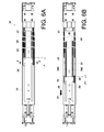
FIG. 6A is a side view in which the slide rail assembly in the first embodiment of the present invention is in a retracted state, with the supporting base at a predetermined position and the second rail at a retracted position relative to the first rail; -
FIG. 6B shows how the second rail of the slide rail assembly in the first embodiment of the present invention is longitudinally displaced to a first extended position relative to the first rail, and how the second rail corresponds to a portion of the supporting base and is supported by the supporting base; -
FIG. 7A shows how the second rail of the slide rail assembly in the first embodiment of the present invention passes through the supporting channel of the supporting base and drives the supporting base to a second supporting position; -
FIG. 7B shows how the third rail of the slide rail assembly in the first embodiment of the present invention is further longitudinally displaced relative to the second rail to bring the slide rail assembly into an extended state; -
FIG. 8 is a sectional view taken along line 8-8 inFIG. 6A , showing how the supporting members support the second rail; -
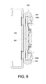
FIG. 9 is a sectional view of the slide rail assembly in the second embodiment of the present invention; -
FIG. 10 is an exploded perspective view of the slide rail assembly in the third embodiment of the present invention; -
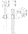
FIG. 11A is a side view in which the slide rail assembly in the third embodiment of the present invention is in a retracted state, with the second rail at a retracted position relative to the first rail; -
FIG. 11B is a side view in which the second rail of the slide rail assembly in the third embodiment of the present invention is at a first extended position relative to the first rail, showing contact between the supporting base and the contact member of the second rail; -
FIG. 11C is a partial enlarged view ofFIG. 11B ; -
FIG. 11D is a side view in which the second rail of the slide rail assembly in the third embodiment of the present invention is at a second extended position relative to the first rail, showing how the supporting base is driven by the contact member to the illustrated position; -
FIG. 11E is a side view in which the second rail of the slide rail assembly in the third embodiment of the present invention is retracted relative to the first rail such that the contact portion of the second rail is in contact with the supporting base; -
FIG. 11F is a partial enlarged view ofFIG. 11E ; -
FIG. 12A shows the arrangement between the contact member and the supporting base in the fourth embodiment of the present invention; -
FIG. 12B shows the arrangement between the second rail and the supporting base in the fourth embodiment of the present invention; -
FIG. 13 shows the arrangement between the bracket base and the supporting base in the fifth embodiment of the present invention; and -
FIG. 14 is a sectional view taken along line 14-14 inFIG. 13 . - Referring to
FIG. 2 , theslide rail assembly 20 in the first embodiment of the present invention includes afirst rail 22, abracket base 24, a supportingbase 26, asecond rail 28, and athird rail 30. Thebracket base 24 has afirst end portion 32 and asecond end portion 34 opposite thefirst end portion 32. Afirst bracket 36 and asecond bracket 38 are mounted adjacent to thefirst end portion 32 and thesecond end portion 34 respectively. For example, thefirst bracket 36 is mounted to thebracket base 24 at a position adjacent to thefirst end portion 32, and thesecond bracket 38 is mounted to thebracket base 24 at a position adjacent to thesecond end portion 34. Thefirst rail 22, thesecond rail 28, and thethird rail 30 are sequentially and longitudinally movably connected and can enter an extended state as a whole. - As shown in
FIG. 2 andFIG. 3 , thefirst rail 22 includes anupper wall 40a, alower wall 40b, and asidewall 42 extending between theupper wall 40a and thelower wall 40b. Theupper wall 40a, thelower wall 40b, and thesidewall 42 jointly define alongitudinal channel 44. - The
bracket base 24 is connected to thefirst rail 22. For example, thebracket base 24 can be connected to thesidewall 42 of thefirst rail 22 by riveting, threaded connection, soldering, or mechanical engagement. Alternatively, thebracket base 24 can be formed at thesidewall 42 of thefirst rail 22 and be viewed as a part of thefirst rail 22. The present invention imposes no limitations on the connection between thebracket base 24 and thefirst rail 22. In this embodiment, thebracket base 24 is riveted to thefirst rail 22 via ariveting element 45. Thebracket base 24 preferably includes at least onelongitudinal groove 46 and in this embodiment has twolongitudinal grooves 46 by way of example. Eachlongitudinal groove 46 is defined between afirst stop wall 48a and asecond stop wall 48b. - The supporting
base 26 is movably mounted to thebracket base 24. The supportingbase 26 includes awall portion 50 and at least one supportingportion 52 connected transversely to thewall portion 50. The supportingbase 26 in this embodiment includes a pair of supportingportions 52 by way of example. The two positions at which the pair of supportingportions 52 are respectively and transversely connected to thewall portion 50 can be on the same side of thewall portion 50, such as an upper position and a corresponding lower position of thewall portion 50. Thewall portion 50 and the pair of supportingportions 52 jointly define a supportingchannel 54 therebetween, wherein the supportingchannel 54 corresponds to thelongitudinal channel 44 of thefirst rail 22. Preferably, a pair of supportingmembers 56 are also included and are mounted to the pair of supportingportions 52 of the supportingbase 26 respectively. In practice, each supportingmember 56 and the corresponding supportingportion 52 can have corresponding structural features, such as a projection and a corresponding hole, to facilitate assembly. Alternatively, the corresponding supportingmember 56 and supportingportion 52 can be put together via at least one additional connecting element. The present invention has no limitations in this regard. The supportingbase 26 can be movably mounted to thebracket base 24 via at least one connectingelement 58. For example, eachlongitudinal groove 46 can be provided with two connectingelements 58, in which each connectingelement 58 includes ahead 60 and abody 62 connected to thehead 60, thehead 60 having a greater diameter than thebody 62. Thebody 62 of each connectingelement 58 can pass through the correspondinglongitudinal groove 46 of thebracket base 24 to connect with thewall portion 50 of the supportingbase 26, with thehead 60 blocked at one side of thebracket base 24. According to this arrangement, the supportingbase 26 can be displaced relative to thebracket base 24 between thefirst stop walls 48a and thesecond stop walls 48b, i.e., as far as the length of thelongitudinal grooves 46 allows. - The
second rail 28 is movably connected to thefirst rail 22 and lies in thelongitudinal channel 44. Thesecond rail 28 includes anupper wall 64a, alower wall 64b, and asidewall 66 extending between theupper wall 64a and thelower wall 64b. -
FIG. 4 shows achassis 68 mounted to arack 70 via a pair ofslide rail assemblies 20. Therack 70 includes two pairs of posts, such as two correspondingfirst posts 72a and two correspondingsecond posts 72b. Eachslide rail assembly 20 has two portions (e.g., a front portion and a rear portion) mounted respectively to onefirst post 72a and onesecond post 72b of therack 70 via thefirst bracket 36 and thesecond bracket 38 such that thechassis 68 is mounted to therack 70. More specifically, thechassis 68 is mounted to thethird rails 30 of theslide rail assemblies 20. Thechassis 68 in this embodiment is a generally T-shaped chassis. For example, thechassis 68 includes afirst portion 74 and asecond portion 76. Thefirst portion 74 has a first width W1 while thesecond portion 76 has a second width W2, wherein the first width W1 is greater than the second width W2. -
FIG. 5A shows theslide rail assembly 20 in an extended state. As the width W1 of thefirst portion 74 of thechassis 68 is greater than the width W2 of thesecond portion 76 of thechassis 68, thefirst portion 74 has an additional thickness S in comparison with thesecond portion 76. Consequently, thethird rail 30 of theslide rail assembly 20 can only be mounted to alateral side 78 of thesecond portion 76 of thechassis 68. And because of that, the weight of thechassis 68 acting on thethird rail 30 needs to be shared by other components, such as thesecond rail 28, especially when theslide rail assembly 20 is in the extended state. In order to cope with the weight of thechassis 68 acting on thethird rail 30, the supportingbase 26, which is movably connected to thebracket base 24, provides additional support for thesecond rail 28 when thesecond rail 28 passes through the supportingbase 26 in the course of being pulled out (i.e., displaced to an extended position) relative to thefirst rail 22.FIG. 5B shows theslide rail assembly 20 in a retracted state in which thechassis 68 is retracted completely into therack 70. -
FIG. 6A shows theslide rail assembly 20 in the retracted state, with both thesecond rail 28 and thethird rail 30 fully retracted relative to thefirst rail 22. In this state, the supportingbase 26 can be adjusted as needed to a predetermined position P relative to thebracket base 24, e.g., to a position near thesecond stop walls 48b (seeFIG. 3 ). Thesecond rail 28, on the other hand, is at a retracted position L relative to thefirst rail 22. - Referring to
FIG. 6B , when thethird rail 30 is pulled out (i.e., displaced in an extending direction as indicated by the arrow) relative to thefirst rail 22, thesecond rail 28 is driven by thethird rail 30 into longitudinal displacement from the retracted position L to a first extended position L1 relative to thefirst rail 22. While thesecond rail 28 is being displaced, a portion of thesecond rail 28 extends out of thelongitudinal channel 44 of thefirst rail 22 and is displaced longitudinally relative to thefirst rail 22 into the supportingchannel 54 of the supportingbase 26, with theupper wall 64a and thelower wall 64b of thesecond rail 28 corresponding to (e.g., in contact with) the pair of supportingmembers 56 of the supportingbase 26 respectively. Thus, thesecond rail 28 drives the supportingbase 26, by friction, from the predetermined position P to a first supporting position P1 relative to thebracket base 24, so that theupper wall 64a and thelower wall 64b of thesecond rail 28 are each supported by a portion of the corresponding supportingmember 56. It is worth mentioning that the thickness of the supportingmembers 56 can be chosen according to practical needs in order to deal with or compensate for possible supporting errors. The goal is to ensure that each supportingmember 56 can support thesecond rail 28 effectively. - Referring to
FIG. 7A , thesecond rail 28, when further driven by thethird rail 30 to a second extended position L2, passes through the supportingchannel 54 of the supportingbase 26 and further drives the supportingbase 26, by friction, from the first supporting position P1 (seeFIG. 6B ) to a second supporting position P2 relative to thebracket base 24, e.g., to a position near thefirst stop walls 48a (seeFIG. 3 ), allowing the pair of supportingmembers 56 of the supportingbase 26 to support, in their entirety, theupper wall 64a and thelower wall 64b of thesecond rail 28 respectively. - Referring to
FIG. 7B , when thesecond rail 28 is at the second extended position L2 (e.g., the farthest extended position), thethird rail 30 can be further pulled out and displaced longitudinally relative to thesecond rail 28 to bring theslide rail assembly 20 into a fully extended state. - It can be known from the above that the
second rail 28 is supported by the supportingbase 26 once displaced relative to thefirst rail 22 into the supportingchannel 54 of the supportingbase 26. When thethird rail 30 is mounted with the chassis 68 (seeFIG. 4 ), therefore, the supportingbase 26 can support thesecond rail 28 in order for thesecond rail 28 to share the weight of thechassis 68 effectively. It is worth mentioning that, while the supportingbase 26 can be displaced by thesecond rail 28 by friction in the course in which thesecond rail 28 is pulled out (i.e., displaced to an extended position) relative to thefirst rail 22, it is also feasible in practice to allow thesecond rail 28 to directly pass through the supportingchannel 54 of the supportingbase 26, and the supportingbase 26 to be manually adjusted by the user to a proper supporting position for supporting thesecond rail 28, with a view to satisfying practical supporting needs. -
FIG. 8 further shows how thebracket base 24, the supportingbase 26, and thesecond rail 28 are arranged with respect to one another. More specifically, theupper wall 64a, thelower wall 64b, and thesidewall 66 of thesecond rail 28 jointly define alongitudinal channel 80 in which thethird rail 30 can be mounted. For example, thelongitudinal channel 80 is mounted therein with aslide facilitating member 82 to assist thethird rail 30 in displacement relative to thesecond rail 28. The supportingbase 26 is movably mounted to thebracket base 24, and the pair of supportingmembers 56 of the supportingbase 26 can be brought into contact with theupper wall 64a and thelower wall 64b of thesecond rail 28 respectively to support thesecond rail 28. -
FIG. 9 shows the slide rail assembly in the second embodiment of the present invention, in particular the configuration of the supportingbase 200. The supportingbase 200 in this embodiment is different from the supportingbase 26 in the first embodiment generally in the following way: when thesecond rail 202 passes through the supportingchannel 204 of the supportingbase 200, the pair of supportingportions 206 of the supportingbase 200 are in direct contact with theupper wall 208a and thelower wall 208b of thesecond rail 202 respectively to support thesecond rail 202. - Referring to
FIG. 10 , the slide rail assembly in the third embodiment of the present invention includes afirst rail 300, asecond rail 302, abracket base 304, and a supportingbase 306. This embodiment is different from the first embodiment generally in that the former further includes acontact member 308 fixedly attached to thesecond rail 302 and having acontact portion 310. Moreover, the supportingbase 306 has afirst feature 312 and asecond feature 314, which are adjacent to two opposite ends of the supportingbase 306 respectively. Thefirst feature 312 of the supportingbase 306 corresponds to thecontact portion 310 of thecontact member 308. Thesecond feature 314 of the supportingbase 306 corresponds to apreset contact portion 316 of thesecond rail 302. - Please note that the
contact member 308 has a predetermined length extending generally along the length of thesecond rail 302 so that thecontact member 308 provides reinforcement to thesecond rail 302. - As shown in
FIG. 11A, FIG. 11B, and FIG. 11C , when thesecond rail 302 is displaced from a retracted position L to a first extended position L1 relative to thefirst rail 300, thefirst feature 312 of the supportingbase 306 abuts against thecontact portion 310 of thecontact member 308. - Referring to
FIG. 11D , thecontact member 308 displaces the supportingbase 306 when thesecond rail 302 is further displaced from the first extended position L1 relative to thefirst rail 300. This arrangement ensures that the supportingbase 306 will be displaced by thecontact member 308 to a predetermined position for supporting thesecond rail 302 when thesecond rail 302 is displaced from the first extended position L1 to a second extended position L2. - Referring to
FIG. 11E and FIG. 11F , when thesecond rail 302 is retracted from the second extended position L2 relative to thefirst rail 300, thecontact portion 316 of thesecond rail 302 will abut against thesecond feature 314 of the supportingbase 306 so that thesecond rail 302 can displace the supportingbase 306 relative to thefirst rail 300 to the position shown inFIG. 11A . -
FIG. 12A and FIG. 12B show how thesecond rail 400 and the supportingbase 402 in the fourth embodiment of the present invention are arranged with respect to each other. This embodiment is different from the third embodiment mainly in that thefirst feature 404 of the supportingbase 402 has afirst end 406a and asecond end 406b corresponding to thefirst end 406a. Thefirst end 406a of thefirst feature 404 corresponds to thecontact portion 410 of thecontact member 408 while thesecond end 406b of thefirst feature 404 corresponds to thecontact portion 412 of thesecond rail 400. According to the arrangement of this embodiment, the supportingbase 402 can provide the same supporting effect as disclosed in the third embodiment. -
FIG. 13 and FIG. 14 show how thebracket base 500 and the supportingbase 502 in the fifth embodiment of the present invention are arranged with respect to each other. This embodiment is different from the previous embodiments mainly in that thebracket base 500 lacks the twolongitudinal grooves 46 of thebracket base 24 in the first embodiment (seeFIG. 3 ), wherein thelongitudinal grooves 46 serve as a mount for the supportingbase 26. In the fifth embodiment, the supportingbase 502 is directly mounted to the main body of thebracket base 500 in a movable manner. - More specifically, the
bracket base 500 has anupper wall 504a, alower wall 504b, and asidewall 506 extending between theupper wall 504a and thelower wall 504b. The supportingbase 502 includes a first supportingbody 508 and a second supportingbody 510. The first supportingbody 508 has a pair ofbent portions 512 and amain body portion 514 extending between and connecting the pair ofbent portions 512. The pair ofbent portions 512 are configured to hold theupper wall 504a and thelower wall 504b of thebracket base 500 respectively in a movable manner. Themain body portion 514 is configured to lie against thesidewall 506 of thebracket base 500. The second supportingbody 510 is fixedly connected to the first supportingbody 508, has the same configuration as the supportingbase 306 in the third embodiment (i.e., corresponding to thelongitudinal channel 518 of the first rail 516), and therefore will not be described repeatedly. - According to the embodiments described above, the present invention advantageously provides a supporting effect when the slide rails are extended relative to one another. Not only that, the present invention uses a supporting design that can be manually adjusted or be driven by slide rail displacement to meet different supporting needs. The supporting design can also adapt to the specifications of the bracket base.
- While the present invention has been disclosed via the above preferred embodiments, those embodiments are not intended to be restrictive of the invention. The scope of patent protection sought by the applicant is defined by the appended claims.
Claims (14)
- A slide rail assembly (20), comprising:a first rail (22, 300, 516) defining a longitudinal channel (44, 518);a bracket base (24, 304, 500) connected to the first rail (22, 300, 516);a supporting base (26, 200, 306, 402, 502) movably mounted to the bracket base (24, 304, 500), the supporting base (26, 200, 306, 402, 502) having a wall portion (50) and at least one supporting portion (52, 206) connected transversely to the wall portion (50), the wall portion (50) and the at least one supporting portion (52, 206) defining a supporting channel (54, 204) therebetween, the supporting channel (54, 204) corresponding to the longitudinal channel (44, 518) of the first rail (22, 300, 516); anda second rail (28, 202, 302, 400) movably connected to the first rail (22, 300, 516) and longitudinally displaceable relative to the first rail (22, 300, 516);wherein the at least one supporting portion (52, 206) of the supporting base (26, 200, 306, 402, 502) supports the second rail (28, 202, 302, 400) when the second rail (28, 202, 302, 400) is displaced relative to the first rail (22, 300, 516) and passes through the longitudinal channel (44, 518) of the first rail (22, 300, 516) and the supporting channel (54, 204) of the supporting base (26, 200, 306, 402, 502).
- The slide rail assembly (20) as claimed in claim 1, wherein the bracket base (24, 304) has at least one longitudinal groove (46), and the slide rail assembly (20) further comprises at least one connecting element (58), the connecting element (58) having a head (60) and a body (62) connected to the head (60), the body (62) passing through the longitudinal groove (46) to connect with the wall portion (50) of the supporting base (26, 200, 306, 402) while the head (60) is blocked at one side of the bracket base (24, 304).
- The slide rail assembly (20) as claimed in claim 1, wherein the supporting base (26, 200, 306, 402, 502) has a pair of said supporting portions (52, 206) connected transversely and respectively to two positions of the wall portion (50), the two positions being on a same side of the wall portion (50), and the wall portion (50) and the pair of supporting portions (52, 206) jointly define the supporting channel (54, 204).
- The slide rail assembly (20) as claimed in claim 3, wherein the second rail (28, 202, 302, 400) has an upper wall (64a, 208a), a lower wall (64b, 208b), and a sidewall (66) extending between the upper wall (64a, 208a) and the lower wall (64b, 208b); and the upper wall (64a, 208a) and the lower wall (64b, 208b) of the second rail (28, 202, 302, 400) correspond to the pair of supporting portions (52, 206) of the supporting base (26, 200, 306, 402, 502) respectively when the second rail (28, 202, 302, 400) is moved into the supporting channel (54, 204) of the supporting base (26, 200, 306, 402, 502).
- The slide rail assembly (20) as claimed in claim 1, further comprising at least one supporting member (56) corresponding and mounted to the at least one supporting portion (52) of the supporting base (26) so that, once moved into the supporting channel (54) of the supporting base (26), the second rail (28) is in contact with the supporting member (56) so as to drive the supporting base (26) into displacement relative to the bracket base (24), with the supporting member (56) supporting the second rail (28).
- The slide rail assembly (20) as claimed in claim 1, wherein the first rail (22, 300, 516) has an upper wall (40a), a lower wall (40b), and a sidewall (42) extending between the upper wall (40a) and the lower wall (40b), the upper wall (40a), the lower wall (40b), and the sidewall (42) jointly defining the longitudinal channel (44, 518); the bracket base (24, 304, 500) is connected to the sidewall (42) of the first rail (22, 300, 516); the second rail (28, 202, 302, 400) is longitudinally displaceable relative to the first rail (22, 300, 516) between a retracted position (L) and an extended position (L1, L2); and the at least one supporting portion (52, 206) of the supporting base (26, 200, 306, 402, 502) supports the second rail (28, 202, 302, 400) while the second rail (28, 202, 302, 400) is being displaced relative to the first rail (22, 300, 516) from the retracted position (L) to the extended position (L1, L2) and passing through the longitudinal channel (44, 518) of the first rail (22, 300, 516) and the supporting channel (54, 204) of the supporting base (26, 200, 306, 402, 502).
- The slide rail assembly (20) as claimed in claim 6, wherein the supporting base (26, 200, 306, 402, 502) has a pair of said supporting portions (52, 206) connected transversely and respectively to two positions of the wall portion (50), the two positions being on a same side of the wall portion (50); the wall portion (50) and the pair of supporting portions (52, 206) jointly define the supporting channel (54, 204); the second rail (28, 202, 302, 400) has an upper wall (64a, 208a), a lower wall (64b, 208b), and a sidewall (66) extending between the upper wall (64a, 208a) and the lower wall (64b, 208b); and the upper wall (64a, 208a) and the lower wall (64b, 208b) of the second rail (28, 202, 302, 400) correspond to the pair of supporting portions (52, 206) of the supporting base (26, 200, 306, 402, 502) respectively while the second rail (28, 202, 302, 400) is passing through the supporting channel (54, 204) of the supporting base (26, 200, 306, 402, 502).
- The slide rail assembly (20) as claimed in claim 7, further comprising a pair of supporting members (56) mounted to the pair of supporting portions (52) of the supporting base (26) respectively so that, while the second rail (28) is passing through the supporting channel (54) of the supporting base (26), the upper wall (64a) and the lower wall (64b) of the second rail (28) are in contact with the pair of supporting members (56) so as to drive the supporting base (26) into displacement relative to the bracket base (24).
- The slide rail assembly (20) as claimed in claim 1, further comprising a third rail (30) longitudinally displaceable relative to the second rail (28, 202, 302, 400), the third rail (30) being configured to mount with a chassis (68), wherein the slide rail assembly (20) is adapted to mount the chassis (68) to a rack (70); the first rail (22, 300, 516) has an upper wall (40a), a lower wall (40b), and a sidewall (42) extending between the upper wall (40a) and the lower wall (40b), the upper wall (40a), the lower wall (40b), and the sidewall (42) jointly defining the longitudinal channel (44, 518); and the bracket base (24, 304, 500) is connected to the sidewall (42) of the first rail (22, 300, 516) and has a first end portion (32) and a second end portion (34) opposite the first end portion (32), there being a first bracket (36) and a second bracket (38) mounted adjacent to the first end portion (32) and the second end portion (34) respectively, the first bracket (36) and the second bracket (38) being mounted to a first post (72a) of the rack (70) and a second post (72b) of the rack (70) respectively.
- The slide rail assembly (20) as claimed in claim 9, wherein the chassis (68) has a first portion (74) and a second portion (76), the first portion (74) has a width (W1) greater than a width (W2) of the second portion (76), and the third rail (30) is configured to be mounted to a lateral side (78) of the second portion (76) of the chassis (68).
- The slide rail assembly (20) as claimed in any one of claims 1, 6, and 9, further comprising a contact member (308) fixedly attached to the second rail (302), the contact member (308) having a contact portion (310), the supporting base (306) having a first feature (312) corresponding to the contact portion (310) of the contact member (308) so that the contact member (308) is able to drive the supporting base (306) into displacement relative to the bracket base (304) when the second rail (302) is displaced relative to the first rail (300) from a first extended position (L1) to a second extended position (L2).
- The slide rail assembly (20) as claimed in claim 11, wherein the supporting base (306) further has a second feature (314) corresponding to a preset contact portion (316) of the second rail (302), and when the second rail (302) is retracted from the second extended position (L2) relative to the first rail (300), the contact portion (316) of the second rail (302) comes into contact with the second feature (314) of the supporting base (306) such that the supporting base (306) is displaced relative to the bracket base (304) by the second rail (302).
- The slide rail assembly (20) as claimed in any one of claims 1, 6, and 9, further comprising a contact member (408) fixedly attached to the second rail (400), the contact member (408) having a contact portion (410), the supporting base (402) having a first feature (404), the first feature (404) having a first end (406a) and a second end (406b) corresponding to the first end (406a), the first end (406a) of the first feature (404) corresponding to the contact portion (410) of the contact member (408), the second end (406a) of the first feature (404) corresponding to a preset contact portion (412) of the second rail (400).
- The slide rail assembly (20) as claimed in any one of claims 1, 6, and 9, wherein the bracket base (500) has an upper wall (504a), a lower wall (504b), and a sidewall (506) extending between the upper wall (504a) and the lower wall (504b); and the supporting base (502) has a first supporting body (508) and a second supporting body (510), the first supporting body (508) having a pair of bent portions (512) and a main body portion (514), the main body portion (514) extending between and connecting the pair of bent portions (512), the pair of bent portions (512) being configured to hold the upper wall (504a) and the lower wall (504b) of the bracket base (500) respectively in a movable manner, the main body portion (514) being configured to lie against the sidewall (506) of the bracket base (500), the second supporting body (510) being fixedly connected to the first supporting body (508), the second supporting body (510) corresponding to the longitudinal channel (518) of the first rail (516).
Applications Claiming Priority (1)
| Application Number | Priority Date | Filing Date | Title |
|---|---|---|---|
| TW104115696A TWI607723B (en) | 2015-05-15 | 2015-05-15 | Slide rail assembly |
Publications (2)
| Publication Number | Publication Date |
|---|---|
| EP3094166A1 true EP3094166A1 (en) | 2016-11-16 |
| EP3094166B1 EP3094166B1 (en) | 2020-01-08 |
Family
ID=54707603
Family Applications (1)
| Application Number | Title | Priority Date | Filing Date |
|---|---|---|---|
| EP15196482.2A Active EP3094166B1 (en) | 2015-05-15 | 2015-11-26 | Slide rail assembly |
Country Status (3)
| Country | Link |
|---|---|
| EP (1) | EP3094166B1 (en) |
| JP (1) | JP6215901B2 (en) |
| TW (1) | TWI607723B (en) |
Cited By (2)
| Publication number | Priority date | Publication date | Assignee | Title |
|---|---|---|---|---|
| CN106681449A (en) * | 2016-12-22 | 2017-05-17 | 广东星徽精密制造股份有限公司 | Easy-disassemble type slide rail |
| CN114060408A (en) * | 2020-08-03 | 2022-02-18 | 川湖科技股份有限公司 | Sliding rail assembly |
Families Citing this family (4)
| Publication number | Priority date | Publication date | Assignee | Title |
|---|---|---|---|---|
| TWI640274B (en) * | 2017-06-20 | 2018-11-11 | 川湖科技股份有限公司 | Slide rail assembly |
| TWI658803B (en) * | 2017-12-28 | 2019-05-11 | 川湖科技股份有限公司 | Slide rail assembly and rail kit thereof |
| TWI700978B (en) * | 2019-04-23 | 2020-08-01 | 川湖科技股份有限公司 | Slide rail assembly |
| TWI730922B (en) * | 2020-10-29 | 2021-06-11 | 川湖科技股份有限公司 | Slide rail assembly |
Citations (5)
| Publication number | Priority date | Publication date | Assignee | Title |
|---|---|---|---|---|
| EP2308349A1 (en) * | 2009-10-08 | 2011-04-13 | Chien-I Chiang | Slide assembly |
| EP2438834A1 (en) * | 2010-10-11 | 2012-04-11 | King Slide Works Co., Ltd. | Reinforcement and adjustment device for slide assembly |
| EP2764796A1 (en) * | 2013-02-08 | 2014-08-13 | King Slide Works Co., Ltd. | Slide rail assembly for use in rack system and reinforcement member thereof |
| EP2777431A1 (en) * | 2013-03-12 | 2014-09-17 | King Slide Works Co., Ltd. | Support structure for support bracket and rail |
| DE102013108217B3 (en) * | 2013-07-31 | 2014-10-16 | Fujitsu Technology Solutions Intellectual Property Gmbh | Slot arrangement for a server rack, as well as holding device for attachment to a server rack |
Family Cites Families (4)
| Publication number | Priority date | Publication date | Assignee | Title |
|---|---|---|---|---|
| JP3182593U (en) * | 2013-01-21 | 2013-04-04 | 川湖科技股▲フン▼有限公司 | Slide rail kit for rack system |
| TWI522063B (en) * | 2013-02-08 | 2016-02-21 | 川湖科技股份有限公司 | Support arrangement for use in a bracket and a slide rail |
| JP3197165U (en) * | 2015-02-10 | 2015-04-23 | 川湖科技股▲分▼有限公司 | Slide rail kit and bracket device thereof |
| JP3197420U (en) * | 2015-02-25 | 2015-05-14 | 川湖科技股▲分▼有限公司 | Slide rail kit |
-
2015
- 2015-05-15 TW TW104115696A patent/TWI607723B/en active
- 2015-11-26 EP EP15196482.2A patent/EP3094166B1/en active Active
- 2015-12-04 JP JP2015237691A patent/JP6215901B2/en active Active
Patent Citations (5)
| Publication number | Priority date | Publication date | Assignee | Title |
|---|---|---|---|---|
| EP2308349A1 (en) * | 2009-10-08 | 2011-04-13 | Chien-I Chiang | Slide assembly |
| EP2438834A1 (en) * | 2010-10-11 | 2012-04-11 | King Slide Works Co., Ltd. | Reinforcement and adjustment device for slide assembly |
| EP2764796A1 (en) * | 2013-02-08 | 2014-08-13 | King Slide Works Co., Ltd. | Slide rail assembly for use in rack system and reinforcement member thereof |
| EP2777431A1 (en) * | 2013-03-12 | 2014-09-17 | King Slide Works Co., Ltd. | Support structure for support bracket and rail |
| DE102013108217B3 (en) * | 2013-07-31 | 2014-10-16 | Fujitsu Technology Solutions Intellectual Property Gmbh | Slot arrangement for a server rack, as well as holding device for attachment to a server rack |
Cited By (3)
| Publication number | Priority date | Publication date | Assignee | Title |
|---|---|---|---|---|
| CN106681449A (en) * | 2016-12-22 | 2017-05-17 | 广东星徽精密制造股份有限公司 | Easy-disassemble type slide rail |
| CN114060408A (en) * | 2020-08-03 | 2022-02-18 | 川湖科技股份有限公司 | Sliding rail assembly |
| CN114060408B (en) * | 2020-08-03 | 2023-06-02 | 川湖科技股份有限公司 | Sliding rail assembly |
Also Published As
| Publication number | Publication date |
|---|---|
| TW201639497A (en) | 2016-11-16 |
| JP2016219775A (en) | 2016-12-22 |
| TWI607723B (en) | 2017-12-11 |
| EP3094166B1 (en) | 2020-01-08 |
| JP6215901B2 (en) | 2017-10-18 |
Similar Documents
| Publication | Publication Date | Title |
|---|---|---|
| US9867308B2 (en) | Slide rail assembly | |
| EP3094166B1 (en) | Slide rail assembly | |
| EP3082387B1 (en) | Slide rail assembly | |
| EP3335590B1 (en) | Mechanism for slide assembly | |
| US10244868B2 (en) | Slide rail assembly | |
| US20160262538A1 (en) | Slide rail assembly | |
| US10010174B2 (en) | Mounting mechanism | |
| US20160278522A1 (en) | Slide rail assembly | |
| US20170055707A1 (en) | Slide rail assembly and bracket thereof | |
| US9572277B2 (en) | Slide rail assembly | |
| US11064807B2 (en) | Slide rail assembly | |
| US10736230B2 (en) | Cable management assembly | |
| US20180368278A1 (en) | Slide rail assembly | |
| EP3258754B1 (en) | Rack system and slide rail assemblies thereof | |
| CN106304747B (en) | Sliding rail assembly | |
| CN108449916A (en) | Slide rail mechanism and bracket device thereof | |
| EP3310033B1 (en) | Slide rail assembly | |
| EP3041329A1 (en) | Cable management arm | |
| EP3030065B1 (en) | Cable management arm supporting device and mounting assembly thereof | |
| EP3073811A1 (en) | Slide rail assembly | |
| EP3772243A1 (en) | Slide rail mechanism | |
| EP3071003B1 (en) | Slide rail assembly | |
| CN108338557A (en) | Sliding rail assembly | |
| US10463150B2 (en) | Slide rail assembly | |
| TWI593336B (en) | Slide rail assembly |
Legal Events
| Date | Code | Title | Description |
|---|---|---|---|
| PUAI | Public reference made under article 153(3) epc to a published international application that has entered the european phase |
Free format text: ORIGINAL CODE: 0009012 |
|
| AK | Designated contracting states |
Kind code of ref document: A1 Designated state(s): AL AT BE BG CH CY CZ DE DK EE ES FI FR GB GR HR HU IE IS IT LI LT LU LV MC MK MT NL NO PL PT RO RS SE SI SK SM TR |
|
| AX | Request for extension of the european patent |
Extension state: BA ME |
|
| STAA | Information on the status of an ep patent application or granted ep patent |
Free format text: STATUS: REQUEST FOR EXAMINATION WAS MADE |
|
| 17P | Request for examination filed |
Effective date: 20170104 |
|
| RBV | Designated contracting states (corrected) |
Designated state(s): AL AT BE BG CH CY CZ DE DK EE ES FI FR GB GR HR HU IE IS IT LI LT LU LV MC MK MT NL NO PL PT RO RS SE SI SK SM TR |
|
| STAA | Information on the status of an ep patent application or granted ep patent |
Free format text: STATUS: EXAMINATION IS IN PROGRESS |
|
| 17Q | First examination report despatched |
Effective date: 20180710 |
|
| GRAP | Despatch of communication of intention to grant a patent |
Free format text: ORIGINAL CODE: EPIDOSNIGR1 |
|
| STAA | Information on the status of an ep patent application or granted ep patent |
Free format text: STATUS: GRANT OF PATENT IS INTENDED |
|
| INTG | Intention to grant announced |
Effective date: 20190717 |
|
| GRAS | Grant fee paid |
Free format text: ORIGINAL CODE: EPIDOSNIGR3 |
|
| GRAA | (expected) grant |
Free format text: ORIGINAL CODE: 0009210 |
|
| STAA | Information on the status of an ep patent application or granted ep patent |
Free format text: STATUS: THE PATENT HAS BEEN GRANTED |
|
| AK | Designated contracting states |
Kind code of ref document: B1 Designated state(s): AL AT BE BG CH CY CZ DE DK EE ES FI FR GB GR HR HU IE IS IT LI LT LU LV MC MK MT NL NO PL PT RO RS SE SI SK SM TR |
|
| REG | Reference to a national code |
Ref country code: GB Ref legal event code: FG4D |
|
| REG | Reference to a national code |
Ref country code: CH Ref legal event code: EP |
|
| REG | Reference to a national code |
Ref country code: IE Ref legal event code: FG4D |
|
| REG | Reference to a national code |
Ref country code: DE Ref legal event code: R096 Ref document number: 602015045075 Country of ref document: DE |
|
| REG | Reference to a national code |
Ref country code: AT Ref legal event code: REF Ref document number: 1224348 Country of ref document: AT Kind code of ref document: T Effective date: 20200215 |
|
| REG | Reference to a national code |
Ref country code: NL Ref legal event code: MP Effective date: 20200108 |
|
| REG | Reference to a national code |
Ref country code: LT Ref legal event code: MG4D |
|
| PG25 | Lapsed in a contracting state [announced via postgrant information from national office to epo] |
Ref country code: NO Free format text: LAPSE BECAUSE OF FAILURE TO SUBMIT A TRANSLATION OF THE DESCRIPTION OR TO PAY THE FEE WITHIN THE PRESCRIBED TIME-LIMIT Effective date: 20200408 Ref country code: PT Free format text: LAPSE BECAUSE OF FAILURE TO SUBMIT A TRANSLATION OF THE DESCRIPTION OR TO PAY THE FEE WITHIN THE PRESCRIBED TIME-LIMIT Effective date: 20200531 Ref country code: FI Free format text: LAPSE BECAUSE OF FAILURE TO SUBMIT A TRANSLATION OF THE DESCRIPTION OR TO PAY THE FEE WITHIN THE PRESCRIBED TIME-LIMIT Effective date: 20200108 Ref country code: RS Free format text: LAPSE BECAUSE OF FAILURE TO SUBMIT A TRANSLATION OF THE DESCRIPTION OR TO PAY THE FEE WITHIN THE PRESCRIBED TIME-LIMIT Effective date: 20200108 Ref country code: NL Free format text: LAPSE BECAUSE OF FAILURE TO SUBMIT A TRANSLATION OF THE DESCRIPTION OR TO PAY THE FEE WITHIN THE PRESCRIBED TIME-LIMIT Effective date: 20200108 Ref country code: LT Free format text: LAPSE BECAUSE OF FAILURE TO SUBMIT A TRANSLATION OF THE DESCRIPTION OR TO PAY THE FEE WITHIN THE PRESCRIBED TIME-LIMIT Effective date: 20200108 |
|
| PG25 | Lapsed in a contracting state [announced via postgrant information from national office to epo] |
Ref country code: BG Free format text: LAPSE BECAUSE OF FAILURE TO SUBMIT A TRANSLATION OF THE DESCRIPTION OR TO PAY THE FEE WITHIN THE PRESCRIBED TIME-LIMIT Effective date: 20200408 Ref country code: IS Free format text: LAPSE BECAUSE OF FAILURE TO SUBMIT A TRANSLATION OF THE DESCRIPTION OR TO PAY THE FEE WITHIN THE PRESCRIBED TIME-LIMIT Effective date: 20200508 Ref country code: SE Free format text: LAPSE BECAUSE OF FAILURE TO SUBMIT A TRANSLATION OF THE DESCRIPTION OR TO PAY THE FEE WITHIN THE PRESCRIBED TIME-LIMIT Effective date: 20200108 Ref country code: LV Free format text: LAPSE BECAUSE OF FAILURE TO SUBMIT A TRANSLATION OF THE DESCRIPTION OR TO PAY THE FEE WITHIN THE PRESCRIBED TIME-LIMIT Effective date: 20200108 Ref country code: HR Free format text: LAPSE BECAUSE OF FAILURE TO SUBMIT A TRANSLATION OF THE DESCRIPTION OR TO PAY THE FEE WITHIN THE PRESCRIBED TIME-LIMIT Effective date: 20200108 |
|
| REG | Reference to a national code |
Ref country code: DE Ref legal event code: R097 Ref document number: 602015045075 Country of ref document: DE |
|
| PG25 | Lapsed in a contracting state [announced via postgrant information from national office to epo] |
Ref country code: ES Free format text: LAPSE BECAUSE OF FAILURE TO SUBMIT A TRANSLATION OF THE DESCRIPTION OR TO PAY THE FEE WITHIN THE PRESCRIBED TIME-LIMIT Effective date: 20200108 Ref country code: DK Free format text: LAPSE BECAUSE OF FAILURE TO SUBMIT A TRANSLATION OF THE DESCRIPTION OR TO PAY THE FEE WITHIN THE PRESCRIBED TIME-LIMIT Effective date: 20200108 Ref country code: SK Free format text: LAPSE BECAUSE OF FAILURE TO SUBMIT A TRANSLATION OF THE DESCRIPTION OR TO PAY THE FEE WITHIN THE PRESCRIBED TIME-LIMIT Effective date: 20200108 Ref country code: SM Free format text: LAPSE BECAUSE OF FAILURE TO SUBMIT A TRANSLATION OF THE DESCRIPTION OR TO PAY THE FEE WITHIN THE PRESCRIBED TIME-LIMIT Effective date: 20200108 Ref country code: CZ Free format text: LAPSE BECAUSE OF FAILURE TO SUBMIT A TRANSLATION OF THE DESCRIPTION OR TO PAY THE FEE WITHIN THE PRESCRIBED TIME-LIMIT Effective date: 20200108 Ref country code: EE Free format text: LAPSE BECAUSE OF FAILURE TO SUBMIT A TRANSLATION OF THE DESCRIPTION OR TO PAY THE FEE WITHIN THE PRESCRIBED TIME-LIMIT Effective date: 20200108 Ref country code: RO Free format text: LAPSE BECAUSE OF FAILURE TO SUBMIT A TRANSLATION OF THE DESCRIPTION OR TO PAY THE FEE WITHIN THE PRESCRIBED TIME-LIMIT Effective date: 20200108 |
|
| PLBE | No opposition filed within time limit |
Free format text: ORIGINAL CODE: 0009261 |
|
| STAA | Information on the status of an ep patent application or granted ep patent |
Free format text: STATUS: NO OPPOSITION FILED WITHIN TIME LIMIT |
|
| REG | Reference to a national code |
Ref country code: AT Ref legal event code: MK05 Ref document number: 1224348 Country of ref document: AT Kind code of ref document: T Effective date: 20200108 |
|
| 26N | No opposition filed |
Effective date: 20201009 |
|
| PG25 | Lapsed in a contracting state [announced via postgrant information from national office to epo] |
Ref country code: IT Free format text: LAPSE BECAUSE OF FAILURE TO SUBMIT A TRANSLATION OF THE DESCRIPTION OR TO PAY THE FEE WITHIN THE PRESCRIBED TIME-LIMIT Effective date: 20200108 Ref country code: AT Free format text: LAPSE BECAUSE OF FAILURE TO SUBMIT A TRANSLATION OF THE DESCRIPTION OR TO PAY THE FEE WITHIN THE PRESCRIBED TIME-LIMIT Effective date: 20200108 |
|
| PG25 | Lapsed in a contracting state [announced via postgrant information from national office to epo] |
Ref country code: PL Free format text: LAPSE BECAUSE OF FAILURE TO SUBMIT A TRANSLATION OF THE DESCRIPTION OR TO PAY THE FEE WITHIN THE PRESCRIBED TIME-LIMIT Effective date: 20200108 Ref country code: SI Free format text: LAPSE BECAUSE OF FAILURE TO SUBMIT A TRANSLATION OF THE DESCRIPTION OR TO PAY THE FEE WITHIN THE PRESCRIBED TIME-LIMIT Effective date: 20200108 |
|
| PG25 | Lapsed in a contracting state [announced via postgrant information from national office to epo] |
Ref country code: MC Free format text: LAPSE BECAUSE OF FAILURE TO SUBMIT A TRANSLATION OF THE DESCRIPTION OR TO PAY THE FEE WITHIN THE PRESCRIBED TIME-LIMIT Effective date: 20200108 |
|
| REG | Reference to a national code |
Ref country code: CH Ref legal event code: PL |
|
| PG25 | Lapsed in a contracting state [announced via postgrant information from national office to epo] |
Ref country code: LU Free format text: LAPSE BECAUSE OF NON-PAYMENT OF DUE FEES Effective date: 20201126 |
|
| REG | Reference to a national code |
Ref country code: BE Ref legal event code: MM Effective date: 20201130 |
|
| PG25 | Lapsed in a contracting state [announced via postgrant information from national office to epo] |
Ref country code: CH Free format text: LAPSE BECAUSE OF NON-PAYMENT OF DUE FEES Effective date: 20201130 Ref country code: LI Free format text: LAPSE BECAUSE OF NON-PAYMENT OF DUE FEES Effective date: 20201130 |
|
| PG25 | Lapsed in a contracting state [announced via postgrant information from national office to epo] |
Ref country code: FR Free format text: LAPSE BECAUSE OF NON-PAYMENT OF DUE FEES Effective date: 20201130 |
|
| PG25 | Lapsed in a contracting state [announced via postgrant information from national office to epo] |
Ref country code: TR Free format text: LAPSE BECAUSE OF FAILURE TO SUBMIT A TRANSLATION OF THE DESCRIPTION OR TO PAY THE FEE WITHIN THE PRESCRIBED TIME-LIMIT Effective date: 20200108 Ref country code: MT Free format text: LAPSE BECAUSE OF FAILURE TO SUBMIT A TRANSLATION OF THE DESCRIPTION OR TO PAY THE FEE WITHIN THE PRESCRIBED TIME-LIMIT Effective date: 20200108 Ref country code: CY Free format text: LAPSE BECAUSE OF FAILURE TO SUBMIT A TRANSLATION OF THE DESCRIPTION OR TO PAY THE FEE WITHIN THE PRESCRIBED TIME-LIMIT Effective date: 20200108 |
|
| PG25 | Lapsed in a contracting state [announced via postgrant information from national office to epo] |
Ref country code: MK Free format text: LAPSE BECAUSE OF FAILURE TO SUBMIT A TRANSLATION OF THE DESCRIPTION OR TO PAY THE FEE WITHIN THE PRESCRIBED TIME-LIMIT Effective date: 20200108 Ref country code: AL Free format text: LAPSE BECAUSE OF FAILURE TO SUBMIT A TRANSLATION OF THE DESCRIPTION OR TO PAY THE FEE WITHIN THE PRESCRIBED TIME-LIMIT Effective date: 20200108 |
|
| PG25 | Lapsed in a contracting state [announced via postgrant information from national office to epo] |
Ref country code: GR Free format text: LAPSE BECAUSE OF FAILURE TO SUBMIT A TRANSLATION OF THE DESCRIPTION OR TO PAY THE FEE WITHIN THE PRESCRIBED TIME-LIMIT Effective date: 20200108 Ref country code: BE Free format text: LAPSE BECAUSE OF NON-PAYMENT OF DUE FEES Effective date: 20201130 |
|
| PGFP | Annual fee paid to national office [announced via postgrant information from national office to epo] |
Ref country code: GB Payment date: 20250909 Year of fee payment: 11 |
|
| PGFP | Annual fee paid to national office [announced via postgrant information from national office to epo] |
Ref country code: IE Payment date: 20250909 Year of fee payment: 11 |
|
| PGFP | Annual fee paid to national office [announced via postgrant information from national office to epo] |
Ref country code: DE Payment date: 20250910 Year of fee payment: 11 |