EP3094107B1 - An audio listening arrangement - Google Patents
An audio listening arrangement Download PDFInfo
- Publication number
- EP3094107B1 EP3094107B1 EP16169107.6A EP16169107A EP3094107B1 EP 3094107 B1 EP3094107 B1 EP 3094107B1 EP 16169107 A EP16169107 A EP 16169107A EP 3094107 B1 EP3094107 B1 EP 3094107B1
- Authority
- EP
- European Patent Office
- Prior art keywords
- ear
- audio listening
- user
- listening device
- audio
- Prior art date
- Legal status (The legal status is an assumption and is not a legal conclusion. Google has not performed a legal analysis and makes no representation as to the accuracy of the status listed.)
- Active
Links
Images

Classifications
-
- H—ELECTRICITY
- H04—ELECTRIC COMMUNICATION TECHNIQUE
- H04R—LOUDSPEAKERS, MICROPHONES, GRAMOPHONE PICK-UPS OR LIKE ACOUSTIC ELECTROMECHANICAL TRANSDUCERS; ELECTRIC HEARING AIDS; PUBLIC ADDRESS SYSTEMS
- H04R1/00—Details of transducers, loudspeakers or microphones
- H04R1/10—Earpieces; Attachments therefor ; Earphones; Monophonic headphones
- H04R1/1016—Earpieces of the intra-aural type
-
- H—ELECTRICITY
- H04—ELECTRIC COMMUNICATION TECHNIQUE
- H04R—LOUDSPEAKERS, MICROPHONES, GRAMOPHONE PICK-UPS OR LIKE ACOUSTIC ELECTROMECHANICAL TRANSDUCERS; ELECTRIC HEARING AIDS; PUBLIC ADDRESS SYSTEMS
- H04R1/00—Details of transducers, loudspeakers or microphones
- H04R1/10—Earpieces; Attachments therefor ; Earphones; Monophonic headphones
- H04R1/105—Earpiece supports, e.g. ear hooks
-
- H—ELECTRICITY
- H04—ELECTRIC COMMUNICATION TECHNIQUE
- H04R—LOUDSPEAKERS, MICROPHONES, GRAMOPHONE PICK-UPS OR LIKE ACOUSTIC ELECTROMECHANICAL TRANSDUCERS; ELECTRIC HEARING AIDS; PUBLIC ADDRESS SYSTEMS
- H04R1/00—Details of transducers, loudspeakers or microphones
- H04R1/10—Earpieces; Attachments therefor ; Earphones; Monophonic headphones
- H04R1/1058—Manufacture or assembly
- H04R1/1066—Constructional aspects of the interconnection between earpiece and earpiece support
-
- H—ELECTRICITY
- H04—ELECTRIC COMMUNICATION TECHNIQUE
- H04R—LOUDSPEAKERS, MICROPHONES, GRAMOPHONE PICK-UPS OR LIKE ACOUSTIC ELECTROMECHANICAL TRANSDUCERS; ELECTRIC HEARING AIDS; PUBLIC ADDRESS SYSTEMS
- H04R1/00—Details of transducers, loudspeakers or microphones
- H04R1/10—Earpieces; Attachments therefor ; Earphones; Monophonic headphones
-
- H—ELECTRICITY
- H04—ELECTRIC COMMUNICATION TECHNIQUE
- H04R—LOUDSPEAKERS, MICROPHONES, GRAMOPHONE PICK-UPS OR LIKE ACOUSTIC ELECTROMECHANICAL TRANSDUCERS; ELECTRIC HEARING AIDS; PUBLIC ADDRESS SYSTEMS
- H04R5/00—Stereophonic arrangements
- H04R5/033—Headphones for stereophonic communication
- H04R5/0335—Earpiece support, e.g. headbands or neckrests
-
- H—ELECTRICITY
- H04—ELECTRIC COMMUNICATION TECHNIQUE
- H04R—LOUDSPEAKERS, MICROPHONES, GRAMOPHONE PICK-UPS OR LIKE ACOUSTIC ELECTROMECHANICAL TRANSDUCERS; ELECTRIC HEARING AIDS; PUBLIC ADDRESS SYSTEMS
- H04R1/00—Details of transducers, loudspeakers or microphones
- H04R1/10—Earpieces; Attachments therefor ; Earphones; Monophonic headphones
- H04R1/1033—Cables or cables storage, e.g. cable reels
Definitions
- the present disclosure relates to an audio listening arrangement to be worn by a user e.g. when listening to audio content.
- a head set makes it possible for a wearer thereof to listen to audio content, such as music or radio broadcasts in environments or situations where it is unsuitable to play the audio content aloud, for example in public spaces where other people may be disturbed.
- audio content such as music or radio broadcasts in environments or situations where it is unsuitable to play the audio content aloud, for example in public spaces where other people may be disturbed.
- a simple form of a head set comprises one or two audio listening devices in the form of miniature loudspeakers or headphones which are attached to a support ribbon which is carried on the head of the user so that the loudspeakers are placed in close proximity to the ears of the user.
- the headset is typically connected to an audio source such as a cellular phone, a radio or an MP3-player.
- Headsets may also be used in situations where the user is physically active. For example, a person performing sports may use a headset to listen to music while running or bicycling. Also police personnel or firefighters may use headsets as a component in a communication system.
- a requirement of a headset for physical activities is that the audio listening devices remain in place in the ears of the user even during long and/or vigorous physical activity. Certain attempts have been made in the art to increase the stability of headsets.
- each audio listening device of the headset is attached to a hook-shaped support designed to surround the ear of the user.
- the hook-shaped support is elastic and bears against the rear part of the user's ear to increase the stability of the position of the audio listening device in the ear of the user.
- the hook-shaped support further extends into a ribbon which passes behind the neck of the user.
- a drawback with the headset of KR101159795 is that the holding function of the hook-shaped support is largely based on the contact with the rear of the user's ear.
- the hook-shaped support may therefore not be sufficiently effective.
- the contact between the hook-shaped support and the rear part of the ear of the user may be uncomfortable, especially during longtime use.
- the head ribbon which interconnects the hook shaped supports may further be considered uncomfortable and less practical to the user, for example in combination with a hat or other head wear.
- EP2277321A1 ( WO2009143055A1 ) shows a headphone with an adjustable hanger bar which is pivotally hinged to a proximal edge surface of a listening element of the headphone.
- US20130114842A1 and US20100124349A1 show headphone adaptors having hook-shaped ear supports.
- US20070071269A1 shows a headset with a ridged behind the neck head-band.
- an object of the present disclosure to achieve an audio listening arrangement comprising an improved ear support for holding the audio listening devices in the ear of a user.
- a further object of the present disclosure is to achieve an audio listening arrangement which may be worn independent of a head ribbon.
- a further object of the present disclosure is to achieve a light-weight and audio listening arrangement.
- Yet a further object of the present disclosure is to achieve a robust audio listening arrangement of simple construction which may be produced at low cost.
- the audio listening arrangement according to the present disclosure was initially intended to be part of a headset in which two audio listing arrangements are interconnected by a cord adapted to extend around the back of the head of the user.
- practical trials have surprisingly shown that when the audio listening arrangement is worn on the head of a user, the ear support is pressed firmly against the sides of the head of a user. This in turn causes the audio listening device to remain sufficiently securely in place in the ear of the user to allow the audio listening arrangement to be used separately, i.e. without being interconnected by a cord. Even during vigorous physical activity over long time.
- the effective holding function of the audio listening arrangement according to the invention is believed to depend on a combinatory effect between, on one hand, the inclination of the ear support towards the head of the user and, on the other hand, the acute angle between the elongated upper support portion and the leg of ear support.
- the combinatory effect is believed to press the bend between the upper support portion and the elongated leg of the ear support into firm contact with the side of the head of the user.
- the second bend B2 increases the radial distance between elongated leg and the outer side of the audio listening device. This in turn makes it possible to increase the inclination of the ear support and thus the strong holding force against the head of the user.
- the end portion of the elongated leg of the ear support is directly attached to the outer side of the audio listening device. This allows for a simple construction and the possibility to produce the audio listening arrangement at low cost. Moreover, since the audio listening arrangement comprises few protruding parts there is less risk that the audio listening arrangement gets entangled in the hair or clothes of the user.
- At least the first bend B1 of the ear support may be manufactured from a resilient material, preferably a rubber material.
- a resilient material preferably a rubber material.
- the inner side of the audio listening device is adapted to be placed in contact with the concha of the ear of the user, whereby the inner side of the audio listening device comprises an audio conducting means for conducting audio signals emitted from a transducer in the audio listening device into the ear canal of the user.
- Practical trials have shown that an excellent holding effect of the audio receiving devices in the ears the user is achieved when the audio listening device has this configuration.
- the audio listening device may comprise a loop for abutment against the ear of the ear of a user.
- the loop fixes the audio listening device even more firmly in the ear of the user.
- FIG. 1 shows schematically a set of two audio listening arrangements 100, 100' according to the disclosure.
- the audio arrangements 100, 100' are identical so therefore only the audio arrangement 100 will be described in detail in the following.
- the audio listening arrangement 100 comprises an audio listening device 110 adapted to be placed in the ear of a user.
- the audio listening device 110 comprises a transducer (not shown in the drawing).
- the transducer which is enclosed within the audio listening device, may be of any type of electric or electronic device capable of receiving electrical signals from a source, and convert the electric signals into acoustic signals, i.e. sound.
- the transducer may comprise an electro-acoustic transducer, such as a loudspeaker.
- the transducer may be connected (not show), by an electrical wire, to a device for transmitting and receiving wireless signals from an electronic audio source, such as a smart phone.
- the wireless communication between the receiving device and the source is preferably achieved by Bluetooth.
- the audio listening device 110 has an inner side 111 which is facing the ear when the audio listening device is placed in the ear of the user. More particularly, at least a portion of the inner side 111 of the audio listening device 110 is adapted to be supported against the concha of the ear of the user. Therefore, the inner side 111, or inner surface 111, is preferably flat.
- the inner side 111 of the audio listening device 110 further comprises an audio conducting means 113 which is adapted to conduct audio signals emitted from the transducer 110 of the audio listening device 110 into the ear canal of the user of the audio listening arrangement.
- the audio conducting means 113 may for example be an in-ear ear plug, as shown in figure 1 .
- An in-ear plug is adapted to extend into the ear canal of the user of the audio listening arrangement and generally provides good sound transmission as well as being comfortable during use.
- the audio conducting means 113 may be an ear bud (not shows in the drawing).
- An ear bud is typically adapted to rest at the entrance of the ear canal of the user of the audio listening arrangement.
- the audio listening device 110 may further be provided with a loop 114 which is arranged to abut the ear of the user. When the audio listening device is inserted in the ear of the user, the loop abuts the antihelix of the ear.
- the loop 114 which is preferably flexible and manufactured from a resilient material such as rubber, may provide extra stability of the audio listening device in the ear of a user. As shown in figure 1 , the loop 114 extends from the inner side 111 of the audio listening device 110.
- the audio listening device 110 further has an outer side 112, which is opposite to the inner side 111 and thus directed radially away from the head of the user.
- the audio listening device 110 further comprises an ear support 120 for holding the audio listening device 110 in place in the ear of a user.
- the ear support 120 comprises an upper elongated support portion 121 which extends substantially horizontally along a first elongated axis X1.
- the elongated support portion 121 has an end 122, which forms a first end 122 of the ear support 120.
- the loop 114 extends towards the first end 122 of the ear support 120.
- the elongated support portion 121 is adapted to be supported on the upper part of the ear of the user of the audio listening arrangement.
- upper part of the ear of the user is meant the upper portion of the ear trumpet, more particularly the area where the upper portion of the ear trumpet is attached to the head of the user.
- Figure 2 shows a side view of the head of a user wearing the audio listening arrangement according to the present invention.
- the support portion 121 rests on the upper part of the ear of the user.
- the upper elongated support portion 121 is interconnected with an elongated leg 125 by means of a first bend B1.
- the elongated leg 125 thereby forms an acute angle V1 with the upper elongated support portion 121.
- the elongated leg 125 should extend upwards in front of the ear trumpet of the user to allow the bend B1 to partially surround the upper forward portion of the ear trumpet.
- the upper, substantially horizontal, support portion 121 may thereby rest comfortably on the upper part of the ear of the user (see figure 2 ). It is further believed that the acute angle V1 between the elongated leg and the upper support portion 121 of the ear support has an influence on the force by which the bend B1 of the ear support is pressed against the sides of the head of the user
- the angle V1 may for example be in the range of 80° - 30° or 80° - 40° or 80° - 50° or 80° - 60 or 80° - 70° or 70° - 30° or 70° - 40° or 70° - 50° or 70° - 60° or 60° - 30° or 60° - 40° or 60° - 50° or 50° - 40° or 50° - 30° or 40° - 30°.
- Practical trials have shown that the bend B1 of the ear support is securely pressed against the sides of the head of the user when the size of the angle VI, V1' is in the range of 50° - 70°, more preferred 50° - 60°, most preferred 55° - 65°.
- the bend B1 is rounded, such that it has an arc shape.
- the bend B1 has a radius in the range of 7 - 12.5 mm when the angle V1 is in the range of 50° - 70°. More preferred the bend B1 has a radius in the range of 7 - 9.5 mm when the angle V1 is in the range of 50° - 60°, most preferred the bend B1 has a radius in the range of 8.5 - 11 mm when the angle V1 is in the range of 55° - 65°.
- the radius of the bend B1 is carefully selected. When the radius is too small, the bend B1 will pinch the ear of the user which may be considered uncomfortable. When the radius is too large, the bend B1 will not fit sufficiently firmly around the forward portion of the ear trumpet of the user.
- the ear support 120 comprises a second end 130 by which the ear support 120 is attached to the outer side 112 of the audio listening device 110.
- the ear support 120 may thereby be formed integrally, i.e. in one piece the audio listening device 110.
- the ear support 120 and the audio listening device 110 are discrete components that are attached to each other, for example by gluing, welding or form fitting.
- the elongated leg 125 of the ear support 120 is attached to the outer side 112 of the audio listening device such that the elongated leg 125 is inclined in direction from the outer side 112 of the audio listening device 110 towards the inner side 111 of the audio listening device 110. More specifically, the elongated leg 125 of the ear support 120 is inclined towards a vertical axis Y1 which extend parallel with the inner side 111 of the audio listening device 110. Since the elongated leg 125 of the ear support 120 is inclined towards the inner side 111 of the audio listening device 110, it forms an acute angle V2 with a horizontal longitudinal axis X2 which extends through the outer side 112 and the inner side 111 of the audio listening device 110.
- the degree of inclination which is defined by angle V2 determines the force by which the upper support portion 121 presses against the head of a user and thereby the stability of the audio listening arrangement on the head of the user.
- the angle V2 may be in the range of 80° - 50° or 80° - 60 or 80° - 70° or 70° - 60° or 75° - 65°.
- the second end 130 of the ear support 120 is interconnected with the longitudinal leg 125 by a second bend B2 so that the elongated leg 125 and the second end 130 forms the angle V2. This is advantageously since it thereby is possible to achieve a large inclination angle V2 of the ear support 120 towards the head of the user.
- the ear support 120 of the audio listening arrangement 100 is preferably manufactured from tube material.
- Tube material is light weight and has the advantage that an electrical cord 140 from, e.g. a device for receiving wireless signals may extend through the hollow ear support 120 to a transducer in the audio listening device.
- the ear support 120 is preferably manufactured from polymer material, for example a thermoplastic material. However, it is also possible to manufacture a portion of the ear support 120 of resilient material, such as an elastomeric material or a rubber material, in order to increase the flexibility of the ear support.
- at least the first bend B1 of the ear support 120 is manufactured from, i.e. comprises resilient material, such as rubber or a TPE material such as styrenic block polymers or polyolefins or elastomeric alloys or thermoplastic polyurethanes of thermoplastic copolyester or thermoplastic polyamides.
- the elongated leg 125 may comprise a leg section 127 of resilient material, which extends from first bend B1 towards the second end 130 of the elongated leg 125.
- the degree of flexibility between the support portion 121 and the elongated leg 125 is increased.
- the audio listening device may comprise a microphone (not shown in the drawings) which may be integrated in one of the ear supports of the audio listening device.
- the microphone may be adapted to be connected to a device for wireless exchange of electrical signals with a receiving unit such as a smart phone.
- Wireless communication is preferably by Bluetooth.
Landscapes
- Engineering & Computer Science (AREA)
- Physics & Mathematics (AREA)
- Acoustics & Sound (AREA)
- Signal Processing (AREA)
- Health & Medical Sciences (AREA)
- Otolaryngology (AREA)
- Manufacturing & Machinery (AREA)
- Headphones And Earphones (AREA)
- Details Of Audible-Bandwidth Transducers (AREA)
Description
- The present disclosure relates to an audio listening arrangement to be worn by a user e.g. when listening to audio content.
- A head set makes it possible for a wearer thereof to listen to audio content, such as music or radio broadcasts in environments or situations where it is unsuitable to play the audio content aloud, for example in public spaces where other people may be disturbed.
- A simple form of a head set comprises one or two audio listening devices in the form of miniature loudspeakers or headphones which are attached to a support ribbon which is carried on the head of the user so that the loudspeakers are placed in close proximity to the ears of the user. The headset is typically connected to an audio source such as a cellular phone, a radio or an MP3-player.
- Headsets may also be used in situations where the user is physically active. For example, a person performing sports may use a headset to listen to music while running or bicycling. Also police personnel or firefighters may use headsets as a component in a communication system.
- A requirement of a headset for physical activities is that the audio listening devices remain in place in the ears of the user even during long and/or vigorous physical activity. Certain attempts have been made in the art to increase the stability of headsets.
- One example of a headset is shown in the published patent application
KR101159795 - A drawback with the headset of
KR101159795 -
EP2277321A1 (WO2009143055A1 ) shows a headphone with an adjustable hanger bar which is pivotally hinged to a proximal edge surface of a listening element of the headphone. -
US20130114842A1 andUS20100124349A1 show headphone adaptors having hook-shaped ear supports. -
US20070071269A1 shows a headset with a ridged behind the neck head-band. -
US20130195310A1 ,WO03075608A1 WO2014051416A1 ,US5412736A ,US20140185821A1 ,US20070248238A1 andUS20080205683A1 EP2081401A2 show various other prior art audio listening arrangements. - Thus, it is an object of the present disclosure to achieve an audio listening arrangement which solves or at least mitigates at least one of the above drawbacks with the prior-art.
- In particular, it is an object of the present disclosure to achieve an audio listening arrangement comprising an improved ear support for holding the audio listening devices in the ear of a user. A further object of the present disclosure is to achieve an audio listening arrangement which may be worn independent of a head ribbon. A further object of the present disclosure is to achieve a light-weight and audio listening arrangement. Yet a further object of the present disclosure is to achieve a robust audio listening arrangement of simple construction which may be produced at low cost.
- According to the present disclosure at least one of these objects is achieved by an audio listening arrangement according to the enclosed claim 1.
- The audio listening arrangement according to the present disclosure was initially intended to be part of a headset in which two audio listing arrangements are interconnected by a cord adapted to extend around the back of the head of the user. However, practical trials have surprisingly shown that when the audio listening arrangement is worn on the head of a user, the ear support is pressed firmly against the sides of the head of a user. This in turn causes the audio listening device to remain sufficiently securely in place in the ear of the user to allow the audio listening arrangement to be used separately, i.e. without being interconnected by a cord. Even during vigorous physical activity over long time.
- The effective holding function of the audio listening arrangement according to the invention is believed to depend on a combinatory effect between, on one hand, the inclination of the ear support towards the head of the user and, on the other hand, the acute angle between the elongated upper support portion and the leg of ear support. The combinatory effect is believed to press the bend between the upper support portion and the elongated leg of the ear support into firm contact with the side of the head of the user.
- The second bend B2 increases the radial distance between elongated leg and the outer side of the audio listening device. This in turn makes it possible to increase the inclination of the ear support and thus the strong holding force against the head of the user.
- According to one embodiment, the end portion of the elongated leg of the ear support is directly attached to the outer side of the audio listening device. This allows for a simple construction and the possibility to produce the audio listening arrangement at low cost. Moreover, since the audio listening arrangement comprises few protruding parts there is less risk that the audio listening arrangement gets entangled in the hair or clothes of the user.
- According to a further embodiment, at least the first bend B1 of the ear support may be manufactured from a resilient material, preferably a rubber material. By making a portion of the ear support in resilient material the ear support becomes more flexible, which has several advantages. For example, the resiliency makes the ear support to abut more strongly against the head of the user. A further advantage is that the resilient bend B1 allows the audio listening arrangement to be used on different head sizes.
- According to the present invention, at least a portion of the inner side of the audio listening device is adapted to be placed in contact with the concha of the ear of the
user, whereby the inner side of the audio listening device comprises an audio conducting means for conducting audio signals emitted from a transducer in the audio listening device into the ear canal of the user. Practical trials have shown that an excellent holding effect of the audio receiving devices in the ears the user is achieved when the audio listening device has this configuration. - According to an embodiment, the audio listening device may comprise a loop for abutment against the ear of the ear of a user. The loop fixes the audio listening device even more firmly in the ear of the user.
-
-
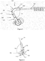
Figure 1 : A schematically perspective drawing of a set of two audio listening arrangements according to a first embodiment of the present invention. -
Figure 2 : A schematically side view drawing of a user wearing an audio listening arrangement according to the invention. -
Figure 3 : A schematically side view drawing of an audio listening arrangement according to the invention. -
Figure 4 : A schematically front view drawing of an audio listening arrangement according to the invention. - The audio listening arrangement according to the present invention will now be described more fully hereinafter.
- Like reference numbers refer to like elements throughout the description.
-
Figure 1 shows schematically a set of twoaudio listening arrangements 100, 100' according to the disclosure. Theaudio arrangements 100, 100' are identical so therefore only theaudio arrangement 100 will be described in detail in the following. Theaudio listening arrangement 100 comprises anaudio listening device 110 adapted to be placed in the ear of a user. Theaudio listening device 110 comprises a transducer (not shown in the drawing). The transducer, which is enclosed within the audio listening device, may be of any type of electric or electronic device capable of receiving electrical signals from a source, and convert the electric signals into acoustic signals, i.e. sound. For example, the transducer may comprise an electro-acoustic transducer, such as a loudspeaker. The transducer may be connected (not show), by an electrical wire, to a device for transmitting and receiving wireless signals from an electronic audio source, such as a smart phone. The wireless communication between the receiving device and the source is preferably achieved by Bluetooth. - The
audio listening device 110 has aninner side 111 which is facing the ear when the audio listening device is placed in the ear of the user. More particularly, at least a portion of theinner side 111 of theaudio listening device 110 is adapted to be supported against the concha of the ear of the user. Therefore, theinner side 111, orinner surface 111, is preferably flat. Theinner side 111 of theaudio listening device 110 further comprises an audio conducting means 113 which is adapted to conduct audio signals emitted from thetransducer 110 of theaudio listening device 110 into the ear canal of the user of the audio listening arrangement. The audio conducting means 113 may for example be an in-ear ear plug, as shown infigure 1 . An in-ear plug is adapted to extend into the ear canal of the user of the audio listening arrangement and generally provides good sound transmission as well as being comfortable during use. Alternatively, the audio conducting means 113 may be an ear bud (not shows in the drawing). An ear bud is typically adapted to rest at the entrance of the ear canal of the user of the audio listening arrangement. - The
audio listening device 110 may further be provided with aloop 114 which is arranged to abut the ear of the user. When the audio listening device is inserted in the ear of the user, the loop abuts the antihelix of the ear. Theloop 114, which is preferably flexible and manufactured from a resilient material such as rubber, may provide extra stability of the audio listening device in the ear of a user. As shown infigure 1 , theloop 114 extends from theinner side 111 of theaudio listening device 110. - The
audio listening device 110 further has anouter side 112, which is opposite to theinner side 111 and thus directed radially away from the head of the user. - The
audio listening device 110 further comprises anear support 120 for holding theaudio listening device 110 in place in the ear of a user. - Turning to
figure 3 , theear support 120 comprises an upperelongated support portion 121 which extends substantially horizontally along a first elongated axis X1. Theelongated support portion 121 has anend 122, which forms afirst end 122 of theear support 120. As shown, theloop 114 extends towards thefirst end 122 of theear support 120. When theear listening device 110 is worn by a wearer, theend 122 of theelongated support portion 121 points in direction of the back of the head of the wearer, i.e. away from the face of the wearer. - The
elongated support portion 121 is adapted to be supported on the upper part of the ear of the user of the audio listening arrangement. By "upper part of the ear" of the user is meant the upper portion of the ear trumpet, more particularly the area where the upper portion of the ear trumpet is attached to the head of the user.Figure 2 shows a side view of the head of a user wearing the audio listening arrangement according to the present invention. - In
figure 2 , thesupport portion 121 rests on the upper part of the ear of the user. - Returning to
figure 3 , the upperelongated support portion 121 is interconnected with anelongated leg 125 by means of a first bend B1. Theelongated leg 125 thereby forms an acute angle V1 with the upperelongated support portion 121. For the function of theear support 120 it is essential that theelongated leg 125 forms an acute angle V1 with thesupport portion 121. One reason therefore is that theelongated leg 125 should extend upwards in front of the ear trumpet of the user to allow the bend B1 to partially surround the upper forward portion of the ear trumpet. The upper, substantially horizontal,support portion 121 may thereby rest comfortably on the upper part of the ear of the user (seefigure 2 ). It is further believed that the acute angle V1 between the elongated leg and theupper support portion 121 of the ear support has an influence on the force by which the bend B1 of the ear support is pressed against the sides of the head of the user - The angle V1 may for example be in the range of 80° - 30° or 80° - 40° or 80° - 50° or 80° - 60 or 80° - 70° or 70° - 30° or 70° - 40° or 70° - 50° or 70° - 60° or 60° - 30° or 60° - 40° or 60° - 50° or 50° - 40° or 50° - 30° or 40° - 30°. Practical trials have shown that the bend B1 of the ear support is securely pressed against the sides of the head of the user when the size of the angle VI, V1' is in the range of 50° - 70°, more preferred 50° - 60°, most preferred 55° - 65°.
- The bend B1 is rounded, such that it has an arc shape. Preferably the bend B1 has a radius in the range of 7 - 12.5 mm when the angle V1 is in the range of 50° - 70°. More preferred the bend B1 has a radius in the range of 7 - 9.5 mm when the angle V1 is in the range of 50° - 60°, most preferred the bend B1 has a radius in the range of 8.5 - 11 mm when the angle V1 is in the range of 55° - 65°. The radius of the bend B1 is carefully selected. When the radius is too small, the bend B1 will pinch the ear of the user which may be considered uncomfortable. When the radius is too large, the bend B1 will not fit sufficiently firmly around the forward portion of the ear trumpet of the user.
- Turning to
figure 4 , theear support 120 comprises asecond end 130 by which theear support 120 is attached to theouter side 112 of theaudio listening device 110. Theear support 120 may thereby be formed integrally, i.e. in one piece theaudio listening device 110. Alternatively, theear support 120 and theaudio listening device 110 are discrete components that are attached to each other, for example by gluing, welding or form fitting. - The
elongated leg 125 of theear support 120 is attached to theouter side 112 of the audio listening device such that theelongated leg 125 is inclined in direction from theouter side 112 of theaudio listening device 110 towards theinner side 111 of theaudio listening device 110. More specifically, theelongated leg 125 of theear support 120 is inclined towards a vertical axis Y1 which extend parallel with theinner side 111 of theaudio listening device 110. Since theelongated leg 125 of theear support 120 is inclined towards theinner side 111 of theaudio listening device 110, it forms an acute angle V2 with a horizontal longitudinal axis X2 which extends through theouter side 112 and theinner side 111 of theaudio listening device 110. - It is important that the
elongated leg 125 of theear support 120 is inclined towards theinner side 113 of theaudio listening device 110 to cause the first bend B1 between the upperelongated support portion 121 and the elongated leg of theear support 120 to press against the sides of a head of the user of the audio listening arrangement. The degree of inclination, which is defined by angle V2 determines the force by which theupper support portion 121 presses against the head of a user and thereby the stability of the audio listening arrangement on the head of the user. The angle V2 may be in the range of 80° - 50° or 80° - 60 or 80° - 70° or 70° - 60° or 75° - 65°. Practical trials have shown that theaudio listening device 110 is held securely in place in the ear of the user when the angle V2 is in the range of 60° - 80° more preferred 65° - 75°. Practical trials further showed that an audio listening arrangement having an angle V2 in the preferred range was found to rest firmly and comfortably on the head of a user. - In
figure 4 , thesecond end 130 of theear support 120 is interconnected with thelongitudinal leg 125 by a second bend B2 so that theelongated leg 125 and thesecond end 130 forms the angle V2. This is advantageously since it thereby is possible to achieve a large inclination angle V2 of theear support 120 towards the head of the user. - It is also possible to attach the
second end 130 of theelongated leg 125 directly onto theouter side 112 of theaudio listening device 110. - Returning to
figure 3 , theear support 120 of theaudio listening arrangement 100 is preferably manufactured from tube material. Tube material is light weight and has the advantage that anelectrical cord 140 from, e.g. a device for receiving wireless signals may extend through thehollow ear support 120 to a transducer in the audio listening device. - The
ear support 120 is preferably manufactured from polymer material, for example a thermoplastic material. However, it is also possible to manufacture a portion of theear support 120 of resilient material, such as an elastomeric material or a rubber material, in order to increase the flexibility of the ear support. Preferably at least the first bend B1 of theear support 120 is manufactured from, i.e. comprises resilient material, such as rubber or a TPE material such as styrenic block polymers or polyolefins or elastomeric alloys or thermoplastic polyurethanes of thermoplastic copolyester or thermoplastic polyamides. - In addition to the bend B1 it is also possible to manufacture a section of the
elongated leg 125 in a resilient material as disclosed above. Thus, theelongated leg 125 may comprise aleg section 127 of resilient material, which extends from first bend B1 towards thesecond end 130 of theelongated leg 125. By also forming a section of the elongated leg in resilient material, the degree of flexibility between thesupport portion 121 and theelongated leg 125 is increased. - Although a particular embodiment has been disclosed in detail this has been done for purpose of illustration only, and is not intended to be limiting. In particular it is contemplated that various substitutions, alterations and modifications may be made within the scope of the appended claims. For example, the audio listening device may comprise a microphone (not shown in the drawings) which may be integrated in one of the ear supports of the audio listening device. The microphone may be adapted to be connected to a device for wireless exchange of electrical signals with a receiving unit such as a smart phone. Wireless communication is preferably by Bluetooth.
- Furthermore, as used herein, the terms "comprise/comprises" or "include/includes" do not exclude the presence of other elements. Finally, reference signs in the claims are provided merely as a clarifying example and should not be construed as limiting the scope of the claims in any way.
Claims (7)
- An audio listening arrangement (100) comprising
an audio listening device (110) adapted to be placed in an ear of a user, wherein the audio listening device (110) comprises an inner side (111) configured to face the ear when the audio listening device is placed in the ear of the user, the inner side (111) comprising audio conducting means (113) for conducting acoustic signals from a transducer arranged in the audio listening device (110) into the ear of the user, wherein at least a portion of the inner side (111) of the audio listening device (110) is adapted to be placed in contact with the concha of the ear of the user, wherein the audio listening device (110) further comprises an outer side (112) which is opposite to the inner side (111) and is directed radially away from the head of the user, and
an ear support (120) for holding the audio listening device (110) in the ear of the user, wherein the ear support (120) comprises:- an elongated support portion (121) extending along a first longitudinal axis (X1) and further adapted to rest on an upper part of the ear of the user, wherein the elongated support portion (121) has a first end (122) forming a first end of the ear support (120), the first end (122) of the ear support (120) pointing towards the back of the head of the user when the audio listening device (110) is placed in the ear of the user, and- an elongated leg (125) which is interconnected with the elongated support portion (121) by means of a first bend (B1) such that the elongated leg (125) forms an acute angle (V1) with the elongated support portion (121), wherebythe ear support (120) is attached to the outer side (112) of the audio listening device (110) by an end portion (130) of the ear support (120) that extends along a second horizontal longitudinal axis (X2), which extends through the outer side (112) and the inner side (111) of the audio listening device (110), and is interconnected with the elongated leg (125) by a second bend (B2) such that the elongated leg (125) is inclined in direction from the outer side (112) of the audio listening device (110) to the inner side (111) of the audio listening device (110) and forms an acute angle (V2) with the second longitudinal axis (X2). - The audio listening arrangement (100) according to claim 1, wherein the end portion (130) is directly attached to the outer side (112) of the audio listening device (110).
- The audio listening arrangement (100) according to anyone of claims 1-2, wherein at least the first bend (B1) comprises a resilient material, preferably a rubber material.
- The audio listening arrangement (100) according to claim 1 - 3, wherein the elongated leg (125) comprises a first leg section (126) extending from the end portion (130) towards the first bend (B1) and a second leg section (127) extending from the first bend (B1) to the first leg section (126), wherein at least the first leg section (126) comprises a rigid material, preferably a rigid polymer material.
- The audio listening arrangement (100) according to claim 4, wherein the second leg section (127), the first bend (B1) and the elongated support portion (121) comprise a resilient material, preferably a rubber material.
- The audio listening arrangement (100) according to anyone of claims 1 - 5, wherein the audio listening device (110) comprises a loop (114) for abutment against the ear of the user.
- The audio listening arrangement (100) according to anyone of claims 1 - 6, wherein the ear support (120) is tubular for receiving an end of a resilient cord (140).
Applications Claiming Priority (1)
| Application Number | Priority Date | Filing Date | Title |
|---|---|---|---|
| SE1550626A SE1550626A1 (en) | 2015-05-15 | 2015-05-15 | An ear support audio listening arrangement |
Publications (2)
| Publication Number | Publication Date |
|---|---|
| EP3094107A1 EP3094107A1 (en) | 2016-11-16 |
| EP3094107B1 true EP3094107B1 (en) | 2021-06-30 |
Family
ID=55968960
Family Applications (1)
| Application Number | Title | Priority Date | Filing Date |
|---|---|---|---|
| EP16169107.6A Active EP3094107B1 (en) | 2015-05-15 | 2016-05-11 | An audio listening arrangement |
Country Status (6)
| Country | Link |
|---|---|
| US (1) | US10149040B2 (en) |
| EP (1) | EP3094107B1 (en) |
| CN (1) | CN106162402B (en) |
| RU (1) | RU2716170C2 (en) |
| SE (1) | SE1550626A1 (en) |
| WO (1) | WO2016186548A1 (en) |
Families Citing this family (6)
| Publication number | Priority date | Publication date | Assignee | Title |
|---|---|---|---|---|
| US12389172B2 (en) | 2014-01-06 | 2025-08-12 | Shenzhen Shokz Co., Ltd. | Systems and methods for suppressing sound leakage |
| US12413915B2 (en) | 2014-01-06 | 2025-09-09 | Shenzhen Shokz Co., Ltd. | Systems and methods for suppressing sound leakage |
| US12506997B2 (en) | 2020-07-29 | 2025-12-23 | Shenzhen Shokz Co., Ltd. | Earphone |
| US12666190B2 (en) | 2020-07-29 | 2026-06-23 | Shenzhen Shokz Co., Ltd. | Earphone |
| US12647713B2 (en) | 2020-07-29 | 2026-06-02 | Shenzhen Shokz Co., Ltd. | Earphone |
| PE20230883A1 (en) | 2020-07-29 | 2023-05-31 | Shenzhen Shokz Co Ltd | HANDSET |
Citations (5)
| Publication number | Priority date | Publication date | Assignee | Title |
|---|---|---|---|---|
| US20070248238A1 (en) * | 2005-12-13 | 2007-10-25 | Abreu Marcio M | Biologically fit wearable electronics apparatus and methods |
| US20080205683A1 (en) * | 2005-01-07 | 2008-08-28 | Frank Michael Weyer | Eyeglass-mountable audio system |
| EP2081401A2 (en) * | 2008-01-17 | 2009-07-22 | Sony Corporation | Headphone |
| US20100124349A1 (en) * | 2008-11-17 | 2010-05-20 | BASS Robert | Earphone ear loop |
| KR101159795B1 (en) * | 2011-06-08 | 2012-06-26 | 삼신이노텍 주식회사 | Portable electronic head set |
Family Cites Families (33)
| Publication number | Priority date | Publication date | Assignee | Title |
|---|---|---|---|---|
| US5210792A (en) * | 1990-08-13 | 1993-05-11 | Matsushita Electric Industrial Co., Ltd. | Ear-hang type headset |
| US5457751A (en) | 1992-01-15 | 1995-10-10 | Such; Ronald W. | Ergonomic headset |
| US5412736A (en) * | 1992-03-23 | 1995-05-02 | Keliiliki; Shawn P. | Personal audio system and earphone for same |
| EP0749263B1 (en) * | 1995-06-13 | 1999-08-25 | Gn Netcom A/S | Headset with adjustable earhook |
| US5761298A (en) * | 1996-05-31 | 1998-06-02 | Plantronics, Inc. | Communications headset with universally adaptable receiver and voice transmitter |
| JP3826478B2 (en) | 1997-03-13 | 2006-09-27 | ソニー株式会社 | Headphone device |
| CN1207643A (en) * | 1997-08-05 | 1999-02-10 | 程滋颐 | Ear hung rest for earphone adapted to be supported entirely by ear |
| JP4123600B2 (en) | 1998-10-16 | 2008-07-23 | ソニー株式会社 | Headphone device |
| JP3500993B2 (en) | 1998-12-10 | 2004-02-23 | 松下電器産業株式会社 | Sound conversion device |
| US6449374B1 (en) * | 1999-03-22 | 2002-09-10 | Plantronics, Inc. | Conformable earhook for an over-the-ear headset |
| EP1495654B1 (en) | 2002-03-02 | 2012-02-01 | Logitech Europe S.A. | Antihelix-conforming ear-mount for personal audio-set |
| US7536008B2 (en) * | 2002-03-02 | 2009-05-19 | Logitech Europe S.A. | Antihelix-conforming ear-mount for personal audio-set |
| US6810987B1 (en) * | 2002-12-06 | 2004-11-02 | Plantronics, Inc. | Earbud headset |
| DE10342532B4 (en) | 2003-09-12 | 2005-09-22 | Sennheiser Electronic Gmbh & Co. Kg | Behind headband headphones |
| SE526944C2 (en) * | 2003-11-27 | 2005-11-22 | Peltor Ab | Ear protection |
| US20080144854A1 (en) | 2006-12-13 | 2008-06-19 | Marcio Marc Abreu | Biologically fit wearable electronics apparatus and methods |
| CN201114704Y (en) * | 2007-04-17 | 2008-09-10 | 李铭 | Simple earphone |
| US7648005B2 (en) | 2007-04-30 | 2010-01-19 | Kimberly-Clark Worldwide, Inc. | Clip-style hearing protector |
| US8374375B2 (en) * | 2007-09-04 | 2013-02-12 | Gn Netcom A/S | Earphone device with bi-stable conchal wall stabilizer |
| EP2277321B1 (en) | 2008-05-19 | 2015-08-26 | Koss Corporation | Adjustable, dual speaker element in-ear phone |
| DE102008047520B4 (en) * | 2008-09-16 | 2021-10-14 | Sennheiser Electronic Gmbh & Co. Kg | In-ear headphones and extension adapter |
| US20130195310A1 (en) | 2010-01-21 | 2013-08-01 | Pi-Fen Lin | Earphone with fixing function and earplug thereof |
| KR20120017920A (en) | 2010-08-20 | 2012-02-29 | 삼신이노텍 주식회사 | Back headband earphone |
| JP5367658B2 (en) | 2010-08-24 | 2013-12-11 | エムケー電子株式会社 | Ear speaker |
| GB2484069A (en) | 2010-09-23 | 2012-04-04 | Jeremy Charles Winterflood | Resilient headband includes releasable means to secure earphones |
| US20130114842A1 (en) | 2011-11-08 | 2013-05-09 | Kurt Jennings | Ear Bud Adaptor |
| WO2014051416A1 (en) | 2012-09-28 | 2014-04-03 | Balda Solutions Malaysia Sdn. Bhd. | An earpiece with adjustable support loop |
| RU2520184C1 (en) | 2012-12-28 | 2014-06-20 | Алексей Леонидович УШАКОВ | Headset of mobile electronic device |
| EP2974360B1 (en) | 2013-03-14 | 2019-09-25 | Harman International Industries, Incorporated | Behind the ear earphone |
| US9319769B2 (en) | 2013-04-15 | 2016-04-19 | Harman International Industries, Incorporated | Wireless headphones |
| CN203181185U (en) * | 2013-04-17 | 2013-09-04 | 邓之建 | Detachable ear hook |
| US8761431B1 (en) | 2013-08-15 | 2014-06-24 | Joelise, LLC | Adjustable headphones |
| US10039928B2 (en) | 2015-03-27 | 2018-08-07 | Equility Llc | Ear stimulation with neural feedback sensing |
-
2015
- 2015-05-15 SE SE1550626A patent/SE1550626A1/en unknown
-
2016
- 2016-05-05 US US15/147,723 patent/US10149040B2/en active Active
- 2016-05-11 WO PCT/SE2016/050421 patent/WO2016186548A1/en not_active Ceased
- 2016-05-11 RU RU2017143762A patent/RU2716170C2/en active
- 2016-05-11 EP EP16169107.6A patent/EP3094107B1/en active Active
- 2016-05-13 CN CN201610314535.5A patent/CN106162402B/en active Active
Patent Citations (5)
| Publication number | Priority date | Publication date | Assignee | Title |
|---|---|---|---|---|
| US20080205683A1 (en) * | 2005-01-07 | 2008-08-28 | Frank Michael Weyer | Eyeglass-mountable audio system |
| US20070248238A1 (en) * | 2005-12-13 | 2007-10-25 | Abreu Marcio M | Biologically fit wearable electronics apparatus and methods |
| EP2081401A2 (en) * | 2008-01-17 | 2009-07-22 | Sony Corporation | Headphone |
| US20100124349A1 (en) * | 2008-11-17 | 2010-05-20 | BASS Robert | Earphone ear loop |
| KR101159795B1 (en) * | 2011-06-08 | 2012-06-26 | 삼신이노텍 주식회사 | Portable electronic head set |
Also Published As
| Publication number | Publication date |
|---|---|
| WO2016186548A1 (en) | 2016-11-24 |
| CN106162402A (en) | 2016-11-23 |
| CN106162402B (en) | 2021-07-06 |
| SE538540C2 (en) | 2016-09-13 |
| US20160337746A1 (en) | 2016-11-17 |
| EP3094107A1 (en) | 2016-11-16 |
| RU2017143762A (en) | 2019-06-17 |
| RU2017143762A3 (en) | 2019-09-25 |
| RU2716170C2 (en) | 2020-03-06 |
| SE1550626A1 (en) | 2016-09-13 |
| US10149040B2 (en) | 2018-12-04 |
Similar Documents
| Publication | Publication Date | Title |
|---|---|---|
| EP3094108B1 (en) | A headset | |
| US10149040B2 (en) | Audio listening arrangement | |
| US9788099B2 (en) | Ear tip with stabilizer | |
| US5953435A (en) | Intra-concha stabilizer with length adjustable conchal wall hook | |
| JP3556151B2 (en) | Transmitter / receiver using bone conduction speaker | |
| US20070165899A1 (en) | Audio headphone | |
| US20130216087A1 (en) | Earbud Positioning Device | |
| JPWO2009116272A1 (en) | Bone conduction speaker and listening device using the same | |
| JP2011521560A (en) | Earpiece and earphone headset | |
| US20080144877A1 (en) | Antihelix stabilizer with easy donning action for wearable audio device | |
| JP2007158924A (en) | Headphone device | |
| EP1969897B1 (en) | Headphones with detachable headband | |
| CN214627313U (en) | Headset gaming headset with dual layer adaptive headbeam | |
| US9301038B2 (en) | Audio headset | |
| KR200468536Y1 (en) | Earphone with Ear Cover | |
| KR101427120B1 (en) | earphone on tragus | |
| JP4867976B2 (en) | Headphone device | |
| CN118509762A (en) | Open wireless earphone | |
| JP5035462B2 (en) | Headphone device |
Legal Events
| Date | Code | Title | Description |
|---|---|---|---|
| PUAI | Public reference made under article 153(3) epc to a published international application that has entered the european phase |
Free format text: ORIGINAL CODE: 0009012 |
|
| AK | Designated contracting states |
Kind code of ref document: A1 Designated state(s): AL AT BE BG CH CY CZ DE DK EE ES FI FR GB GR HR HU IE IS IT LI LT LU LV MC MK MT NL NO PL PT RO RS SE SI SK SM TR |
|
| AX | Request for extension of the european patent |
Extension state: BA ME |
|
| STAA | Information on the status of an ep patent application or granted ep patent |
Free format text: STATUS: REQUEST FOR EXAMINATION WAS MADE |
|
| 17P | Request for examination filed |
Effective date: 20170515 |
|
| RBV | Designated contracting states (corrected) |
Designated state(s): AL AT BE BG CH CY CZ DE DK EE ES FI FR GB GR HR HU IE IS IT LI LT LU LV MC MK MT NL NO PL PT RO RS SE SI SK SM TR |
|
| STAA | Information on the status of an ep patent application or granted ep patent |
Free format text: STATUS: EXAMINATION IS IN PROGRESS |
|
| 17Q | First examination report despatched |
Effective date: 20190506 |
|
| GRAP | Despatch of communication of intention to grant a patent |
Free format text: ORIGINAL CODE: EPIDOSNIGR1 |
|
| STAA | Information on the status of an ep patent application or granted ep patent |
Free format text: STATUS: GRANT OF PATENT IS INTENDED |
|
| INTG | Intention to grant announced |
Effective date: 20201221 |
|
| GRAS | Grant fee paid |
Free format text: ORIGINAL CODE: EPIDOSNIGR3 |
|
| GRAA | (expected) grant |
Free format text: ORIGINAL CODE: 0009210 |
|
| STAA | Information on the status of an ep patent application or granted ep patent |
Free format text: STATUS: THE PATENT HAS BEEN GRANTED |
|
| AK | Designated contracting states |
Kind code of ref document: B1 Designated state(s): AL AT BE BG CH CY CZ DE DK EE ES FI FR GB GR HR HU IE IS IT LI LT LU LV MC MK MT NL NO PL PT RO RS SE SI SK SM TR |
|
| REG | Reference to a national code |
Ref country code: CH Ref legal event code: EP |
|
| REG | Reference to a national code |
Ref country code: AT Ref legal event code: REF Ref document number: 1407508 Country of ref document: AT Kind code of ref document: T Effective date: 20210715 |
|
| REG | Reference to a national code |
Ref country code: DE Ref legal event code: R096 Ref document number: 602016059884 Country of ref document: DE |
|
| REG | Reference to a national code |
Ref country code: IE Ref legal event code: FG4D |
|
| REG | Reference to a national code |
Ref country code: LT Ref legal event code: MG9D |
|
| PG25 | Lapsed in a contracting state [announced via postgrant information from national office to epo] |
Ref country code: BG Free format text: LAPSE BECAUSE OF FAILURE TO SUBMIT A TRANSLATION OF THE DESCRIPTION OR TO PAY THE FEE WITHIN THE PRESCRIBED TIME-LIMIT Effective date: 20210930 Ref country code: HR Free format text: LAPSE BECAUSE OF FAILURE TO SUBMIT A TRANSLATION OF THE DESCRIPTION OR TO PAY THE FEE WITHIN THE PRESCRIBED TIME-LIMIT Effective date: 20210630 Ref country code: FI Free format text: LAPSE BECAUSE OF FAILURE TO SUBMIT A TRANSLATION OF THE DESCRIPTION OR TO PAY THE FEE WITHIN THE PRESCRIBED TIME-LIMIT Effective date: 20210630 |
|
| REG | Reference to a national code |
Ref country code: NL Ref legal event code: MP Effective date: 20210630 |
|
| REG | Reference to a national code |
Ref country code: AT Ref legal event code: MK05 Ref document number: 1407508 Country of ref document: AT Kind code of ref document: T Effective date: 20210630 |
|
| PG25 | Lapsed in a contracting state [announced via postgrant information from national office to epo] |
Ref country code: SE Free format text: LAPSE BECAUSE OF FAILURE TO SUBMIT A TRANSLATION OF THE DESCRIPTION OR TO PAY THE FEE WITHIN THE PRESCRIBED TIME-LIMIT Effective date: 20210630 Ref country code: RS Free format text: LAPSE BECAUSE OF FAILURE TO SUBMIT A TRANSLATION OF THE DESCRIPTION OR TO PAY THE FEE WITHIN THE PRESCRIBED TIME-LIMIT Effective date: 20210630 Ref country code: NO Free format text: LAPSE BECAUSE OF FAILURE TO SUBMIT A TRANSLATION OF THE DESCRIPTION OR TO PAY THE FEE WITHIN THE PRESCRIBED TIME-LIMIT Effective date: 20210930 Ref country code: GR Free format text: LAPSE BECAUSE OF FAILURE TO SUBMIT A TRANSLATION OF THE DESCRIPTION OR TO PAY THE FEE WITHIN THE PRESCRIBED TIME-LIMIT Effective date: 20211001 Ref country code: LV Free format text: LAPSE BECAUSE OF FAILURE TO SUBMIT A TRANSLATION OF THE DESCRIPTION OR TO PAY THE FEE WITHIN THE PRESCRIBED TIME-LIMIT Effective date: 20210630 |
|
| PG25 | Lapsed in a contracting state [announced via postgrant information from national office to epo] |
Ref country code: AT Free format text: LAPSE BECAUSE OF FAILURE TO SUBMIT A TRANSLATION OF THE DESCRIPTION OR TO PAY THE FEE WITHIN THE PRESCRIBED TIME-LIMIT Effective date: 20210630 Ref country code: ES Free format text: LAPSE BECAUSE OF FAILURE TO SUBMIT A TRANSLATION OF THE DESCRIPTION OR TO PAY THE FEE WITHIN THE PRESCRIBED TIME-LIMIT Effective date: 20210630 Ref country code: PT Free format text: LAPSE BECAUSE OF FAILURE TO SUBMIT A TRANSLATION OF THE DESCRIPTION OR TO PAY THE FEE WITHIN THE PRESCRIBED TIME-LIMIT Effective date: 20211102 Ref country code: NL Free format text: LAPSE BECAUSE OF FAILURE TO SUBMIT A TRANSLATION OF THE DESCRIPTION OR TO PAY THE FEE WITHIN THE PRESCRIBED TIME-LIMIT Effective date: 20210630 Ref country code: RO Free format text: LAPSE BECAUSE OF FAILURE TO SUBMIT A TRANSLATION OF THE DESCRIPTION OR TO PAY THE FEE WITHIN THE PRESCRIBED TIME-LIMIT Effective date: 20210630 Ref country code: CZ Free format text: LAPSE BECAUSE OF FAILURE TO SUBMIT A TRANSLATION OF THE DESCRIPTION OR TO PAY THE FEE WITHIN THE PRESCRIBED TIME-LIMIT Effective date: 20210630 Ref country code: EE Free format text: LAPSE BECAUSE OF FAILURE TO SUBMIT A TRANSLATION OF THE DESCRIPTION OR TO PAY THE FEE WITHIN THE PRESCRIBED TIME-LIMIT Effective date: 20210630 Ref country code: SM Free format text: LAPSE BECAUSE OF FAILURE TO SUBMIT A TRANSLATION OF THE DESCRIPTION OR TO PAY THE FEE WITHIN THE PRESCRIBED TIME-LIMIT Effective date: 20210630 Ref country code: SK Free format text: LAPSE BECAUSE OF FAILURE TO SUBMIT A TRANSLATION OF THE DESCRIPTION OR TO PAY THE FEE WITHIN THE PRESCRIBED TIME-LIMIT Effective date: 20210630 |
|
| PG25 | Lapsed in a contracting state [announced via postgrant information from national office to epo] |
Ref country code: PL Free format text: LAPSE BECAUSE OF FAILURE TO SUBMIT A TRANSLATION OF THE DESCRIPTION OR TO PAY THE FEE WITHIN THE PRESCRIBED TIME-LIMIT Effective date: 20210630 |
|
| REG | Reference to a national code |
Ref country code: DE Ref legal event code: R097 Ref document number: 602016059884 Country of ref document: DE |
|
| PG25 | Lapsed in a contracting state [announced via postgrant information from national office to epo] |
Ref country code: DK Free format text: LAPSE BECAUSE OF FAILURE TO SUBMIT A TRANSLATION OF THE DESCRIPTION OR TO PAY THE FEE WITHIN THE PRESCRIBED TIME-LIMIT Effective date: 20210630 |
|
| PLBE | No opposition filed within time limit |
Free format text: ORIGINAL CODE: 0009261 |
|
| STAA | Information on the status of an ep patent application or granted ep patent |
Free format text: STATUS: NO OPPOSITION FILED WITHIN TIME LIMIT |
|
| PG25 | Lapsed in a contracting state [announced via postgrant information from national office to epo] |
Ref country code: AL Free format text: LAPSE BECAUSE OF FAILURE TO SUBMIT A TRANSLATION OF THE DESCRIPTION OR TO PAY THE FEE WITHIN THE PRESCRIBED TIME-LIMIT Effective date: 20210630 |
|
| 26N | No opposition filed |
Effective date: 20220331 |
|
| PG25 | Lapsed in a contracting state [announced via postgrant information from national office to epo] |
Ref country code: IT Free format text: LAPSE BECAUSE OF FAILURE TO SUBMIT A TRANSLATION OF THE DESCRIPTION OR TO PAY THE FEE WITHIN THE PRESCRIBED TIME-LIMIT Effective date: 20210630 |
|
| REG | Reference to a national code |
Ref country code: CH Ref legal event code: PL |
|
| REG | Reference to a national code |
Ref country code: BE Ref legal event code: MM Effective date: 20220531 |
|
| PG25 | Lapsed in a contracting state [announced via postgrant information from national office to epo] |
Ref country code: MC Free format text: LAPSE BECAUSE OF FAILURE TO SUBMIT A TRANSLATION OF THE DESCRIPTION OR TO PAY THE FEE WITHIN THE PRESCRIBED TIME-LIMIT Effective date: 20210630 Ref country code: LU Free format text: LAPSE BECAUSE OF NON-PAYMENT OF DUE FEES Effective date: 20220511 Ref country code: LI Free format text: LAPSE BECAUSE OF NON-PAYMENT OF DUE FEES Effective date: 20220531 Ref country code: CH Free format text: LAPSE BECAUSE OF NON-PAYMENT OF DUE FEES Effective date: 20220531 |
|
| PG25 | Lapsed in a contracting state [announced via postgrant information from national office to epo] |
Ref country code: LT Free format text: LAPSE BECAUSE OF FAILURE TO SUBMIT A TRANSLATION OF THE DESCRIPTION OR TO PAY THE FEE WITHIN THE PRESCRIBED TIME-LIMIT Effective date: 20210630 Ref country code: IE Free format text: LAPSE BECAUSE OF NON-PAYMENT OF DUE FEES Effective date: 20220511 |
|
| PG25 | Lapsed in a contracting state [announced via postgrant information from national office to epo] |
Ref country code: BE Free format text: LAPSE BECAUSE OF NON-PAYMENT OF DUE FEES Effective date: 20220531 |
|
| P01 | Opt-out of the competence of the unified patent court (upc) registered |
Effective date: 20230508 |
|
| PG25 | Lapsed in a contracting state [announced via postgrant information from national office to epo] |
Ref country code: HU Free format text: LAPSE BECAUSE OF FAILURE TO SUBMIT A TRANSLATION OF THE DESCRIPTION OR TO PAY THE FEE WITHIN THE PRESCRIBED TIME-LIMIT; INVALID AB INITIO Effective date: 20160511 |
|
| PG25 | Lapsed in a contracting state [announced via postgrant information from national office to epo] |
Ref country code: MK Free format text: LAPSE BECAUSE OF FAILURE TO SUBMIT A TRANSLATION OF THE DESCRIPTION OR TO PAY THE FEE WITHIN THE PRESCRIBED TIME-LIMIT Effective date: 20210630 Ref country code: CY Free format text: LAPSE BECAUSE OF FAILURE TO SUBMIT A TRANSLATION OF THE DESCRIPTION OR TO PAY THE FEE WITHIN THE PRESCRIBED TIME-LIMIT Effective date: 20210630 |
|
| PG25 | Lapsed in a contracting state [announced via postgrant information from national office to epo] |
Ref country code: TR Free format text: LAPSE BECAUSE OF FAILURE TO SUBMIT A TRANSLATION OF THE DESCRIPTION OR TO PAY THE FEE WITHIN THE PRESCRIBED TIME-LIMIT Effective date: 20210630 |
|
| PG25 | Lapsed in a contracting state [announced via postgrant information from national office to epo] |
Ref country code: MT Free format text: LAPSE BECAUSE OF FAILURE TO SUBMIT A TRANSLATION OF THE DESCRIPTION OR TO PAY THE FEE WITHIN THE PRESCRIBED TIME-LIMIT Effective date: 20210630 |
|
| PGFP | Annual fee paid to national office [announced via postgrant information from national office to epo] |
Ref country code: GB Payment date: 20260511 Year of fee payment: 11 |
|
| PGFP | Annual fee paid to national office [announced via postgrant information from national office to epo] |
Ref country code: DE Payment date: 20260511 Year of fee payment: 11 |
|
| PGFP | Annual fee paid to national office [announced via postgrant information from national office to epo] |
Ref country code: FR Payment date: 20260512 Year of fee payment: 11 |