EP3093902A1 - String trimmer battery housing assembley - Google Patents
String trimmer battery housing assembley Download PDFInfo
- Publication number
- EP3093902A1 EP3093902A1 EP16169032.6A EP16169032A EP3093902A1 EP 3093902 A1 EP3093902 A1 EP 3093902A1 EP 16169032 A EP16169032 A EP 16169032A EP 3093902 A1 EP3093902 A1 EP 3093902A1
- Authority
- EP
- European Patent Office
- Prior art keywords
- battery
- assembly
- base housing
- base
- battery housing
- Prior art date
- Legal status (The legal status is an assumption and is not a legal conclusion. Google has not performed a legal analysis and makes no representation as to the accuracy of the status listed.)
- Granted
Links
Images





Classifications
-
- A—HUMAN NECESSITIES
- A01—AGRICULTURE; FORESTRY; ANIMAL HUSBANDRY; HUNTING; TRAPPING; FISHING
- A01D—HARVESTING; MOWING
- A01D34/00—Mowers; Mowing apparatus of harvesters
- A01D34/01—Mowers; Mowing apparatus of harvesters characterised by features relating to the type of cutting apparatus
- A01D34/412—Mowers; Mowing apparatus of harvesters characterised by features relating to the type of cutting apparatus having rotating cutters
- A01D34/416—Flexible line cutters
-
- A—HUMAN NECESSITIES
- A01—AGRICULTURE; FORESTRY; ANIMAL HUSBANDRY; HUNTING; TRAPPING; FISHING
- A01D—HARVESTING; MOWING
- A01D34/00—Mowers; Mowing apparatus of harvesters
- A01D34/01—Mowers; Mowing apparatus of harvesters characterised by features relating to the type of cutting apparatus
- A01D34/412—Mowers; Mowing apparatus of harvesters characterised by features relating to the type of cutting apparatus having rotating cutters
- A01D34/63—Mowers; Mowing apparatus of harvesters characterised by features relating to the type of cutting apparatus having rotating cutters having cutters rotating about a vertical axis
- A01D34/76—Driving mechanisms for the cutters
- A01D34/78—Driving mechanisms for the cutters electric
-
- A—HUMAN NECESSITIES
- A01—AGRICULTURE; FORESTRY; ANIMAL HUSBANDRY; HUNTING; TRAPPING; FISHING
- A01D—HARVESTING; MOWING
- A01D34/00—Mowers; Mowing apparatus of harvesters
- A01D34/01—Mowers; Mowing apparatus of harvesters characterised by features relating to the type of cutting apparatus
- A01D34/412—Mowers; Mowing apparatus of harvesters characterised by features relating to the type of cutting apparatus having rotating cutters
- A01D34/63—Mowers; Mowing apparatus of harvesters characterised by features relating to the type of cutting apparatus having rotating cutters having cutters rotating about a vertical axis
- A01D34/82—Other details
- A01D34/828—Safety devices
-
- B—PERFORMING OPERATIONS; TRANSPORTING
- B25—HAND TOOLS; PORTABLE POWER-DRIVEN TOOLS; MANIPULATORS
- B25F—COMBINATION OR MULTI-PURPOSE TOOLS NOT OTHERWISE PROVIDED FOR; DETAILS OR COMPONENTS OF PORTABLE POWER-DRIVEN TOOLS NOT PARTICULARLY RELATED TO THE OPERATIONS PERFORMED AND NOT OTHERWISE PROVIDED FOR
- B25F5/00—Details or components of portable power-driven tools not particularly related to the operations performed and not otherwise provided for
-
- H—ELECTRICITY
- H01—ELECTRIC ELEMENTS
- H01M—PROCESSES OR MEANS, e.g. BATTERIES, FOR THE DIRECT CONVERSION OF CHEMICAL ENERGY INTO ELECTRICAL ENERGY
- H01M50/00—Constructional details or processes of manufacture of the non-active parts of electrochemical cells other than fuel cells, e.g. hybrid cells
- H01M50/20—Mountings; Secondary casings or frames; Racks, modules or packs; Suspension devices; Shock absorbers; Transport or carrying devices; Holders
- H01M50/218—Mountings; Secondary casings or frames; Racks, modules or packs; Suspension devices; Shock absorbers; Transport or carrying devices; Holders characterised by the material
- H01M50/22—Mountings; Secondary casings or frames; Racks, modules or packs; Suspension devices; Shock absorbers; Transport or carrying devices; Holders characterised by the material of the casings or racks
- H01M50/227—Organic material
-
- H—ELECTRICITY
- H01—ELECTRIC ELEMENTS
- H01M—PROCESSES OR MEANS, e.g. BATTERIES, FOR THE DIRECT CONVERSION OF CHEMICAL ENERGY INTO ELECTRICAL ENERGY
- H01M50/00—Constructional details or processes of manufacture of the non-active parts of electrochemical cells other than fuel cells, e.g. hybrid cells
- H01M50/20—Mountings; Secondary casings or frames; Racks, modules or packs; Suspension devices; Shock absorbers; Transport or carrying devices; Holders
- H01M50/233—Mountings; Secondary casings or frames; Racks, modules or packs; Suspension devices; Shock absorbers; Transport or carrying devices; Holders characterised by physical properties of casings or racks, e.g. dimensions
- H01M50/242—Mountings; Secondary casings or frames; Racks, modules or packs; Suspension devices; Shock absorbers; Transport or carrying devices; Holders characterised by physical properties of casings or racks, e.g. dimensions adapted for protecting batteries against vibrations, collision impact or swelling
-
- H—ELECTRICITY
- H01—ELECTRIC ELEMENTS
- H01M—PROCESSES OR MEANS, e.g. BATTERIES, FOR THE DIRECT CONVERSION OF CHEMICAL ENERGY INTO ELECTRICAL ENERGY
- H01M2220/00—Batteries for particular applications
- H01M2220/30—Batteries in portable systems, e.g. mobile phone, laptop
-
- H—ELECTRICITY
- H01—ELECTRIC ELEMENTS
- H01M—PROCESSES OR MEANS, e.g. BATTERIES, FOR THE DIRECT CONVERSION OF CHEMICAL ENERGY INTO ELECTRICAL ENERGY
- H01M50/00—Constructional details or processes of manufacture of the non-active parts of electrochemical cells other than fuel cells, e.g. hybrid cells
- H01M50/20—Mountings; Secondary casings or frames; Racks, modules or packs; Suspension devices; Shock absorbers; Transport or carrying devices; Holders
- H01M50/233—Mountings; Secondary casings or frames; Racks, modules or packs; Suspension devices; Shock absorbers; Transport or carrying devices; Holders characterised by physical properties of casings or racks, e.g. dimensions
- H01M50/24—Mountings; Secondary casings or frames; Racks, modules or packs; Suspension devices; Shock absorbers; Transport or carrying devices; Holders characterised by physical properties of casings or racks, e.g. dimensions adapted for protecting batteries from their environment, e.g. from corrosion
-
- Y—GENERAL TAGGING OF NEW TECHNOLOGICAL DEVELOPMENTS; GENERAL TAGGING OF CROSS-SECTIONAL TECHNOLOGIES SPANNING OVER SEVERAL SECTIONS OF THE IPC; TECHNICAL SUBJECTS COVERED BY FORMER USPC CROSS-REFERENCE ART COLLECTIONS [XRACs] AND DIGESTS
- Y02—TECHNOLOGIES OR APPLICATIONS FOR MITIGATION OR ADAPTATION AGAINST CLIMATE CHANGE
- Y02E—REDUCTION OF GREENHOUSE GAS [GHG] EMISSIONS, RELATED TO ENERGY GENERATION, TRANSMISSION OR DISTRIBUTION
- Y02E60/00—Enabling technologies; Technologies with a potential or indirect contribution to GHG emissions mitigation
- Y02E60/10—Energy storage using batteries
Definitions
- the present invention relates to a battery-powered string trimmer. More particularly, the invention relates to a battery-powered string trimmer having a battery housing assembly, configured to protect the battery from impacts and permit easy storage.
- string trimmers are generally used for horizontal trimming and vertical edging of lawn.
- string trimmers include a handle, a motor, a power source, and an elongated shaft and a lower cutting head from which the string cutting element extends and rotates to cut grass, weeds, and other vegetation.
- String trimmers may be powered by combustible fuel engines or electric motors.
- the versions driven by electric motors may be connected to a line source such as 120 volt alternating current electric power, or they may be powered by a battery pack or other source of direct current electrical power.
- Most battery-powered string trimmers conventionally have a motor provided at a lower end of the elongated shaft and are actuated by a trigger provided in the handle assembly.
- Some conventional battery-powered string trimmers provide the battery in conjunction with the handle assembly, as a unitary system, while other string trimmers provide the battery at the opposing end portion of the elongated support shaft. In both of these configurations, the battery and/or housing is susceptible to damage if dropped on a surface.
- batteries used to power handheld devices are relatively heavy, as well as expensive.
- the overall weight of the battery may on occasion cause the user to accidentally drop the battery end of the string trimmer, causing the battery housing to forcibly impact a surrounding surface.
- the overall weight of the battery, and thus force of the impact may cause damage to the housing of the string trimmer, and/or to the battery itself.
- a battery housing assembly for an outdoor power tool comprising:
- the top member of the base housing member may include a first groove member and a second groove member configured to engage a top portion of the battery therein to facilitate fastening of the battery within the base housing member.
- the top member of the base housing member may provide a latch member configured to selectively engage a top portion of an inserted battery to facilitate securing the battery within the battery housing.
- the exterior of the top portion of the base housing member may include a composite rubber adapted to support a user's forearm when in use.
- first side member and second side member are comprised of a resilient material to absorb impacts.
- first and second support brackets may also be provided on both the first side and second side of the base housing member, the first and second support brackets connecting the top member and the bottom member, wherein the first and second side members may include a groove for receiving a support bracket.
- each side member has at least one projection extending beyond the rear boundary of the base housing portion.
- a skid plate assembly connected to the base housing member.
- the skid plate assembly may include a base portion and an extension portion, the extension portion possibly extending upwardly from the base portion to partially shield the rear of the battery housing assembly.
- the skid plate assembly may form a cavity with the base housing member.
- Each side member may have at least one projection extending beyond the rear boundary of the base housing portion, wherein the extension portion of the skid plate assembly and the at least one projection may cooperatively protect a back portion of the battery.
- the skid plate assembly may form a generally U-shaped configuration with the base housing member to provide a hook for hanging the outdoor power tool.
- the skid plate assembly may have a resilient body configured to absorb an impact.
- an outdoor powertool having the battery housing assembly as described above.
- the first and second side members may be removable from the base housing member.
- the battery housing assembly may further include a first support bracket on the first side of the base housing member and a second support bracket on the second side of the housing member, wherein the first side member are secured to the first support bracket and the second side member is secured to the second support bracket.
- the top member may include a resilient outer surface to provide a forearm support surface.
- an outdoor power tool having battery housing assembly comprising:
- projections may extend rearwardly from one or more of the top, bottom or side members so that the projections extend beyond the battery
- a skid plate assembly including a base member and an extension portion, the extension portion extending upwardly from the base portion to partially shield a rear opening of the battery housing assembly.
- the skid plate assembly may form a generally U-shaped configuration with the base housing member to provide a hook for hanging the string trimmer.
- the skid plate assembly may have a resilient body configured to absorb an impact.
- first and second side members are removable from the base housing member.
- the top member may include a resilient outer surface to provide a forearm support surface.
- the elongated configuration has several key components provided across an extended distance, which makes it difficult for a user to fully protect the components at all times. For example, components at the end of the string trimmer opposite the cutting head, such as the battery, may extend beyond the user's body resulting in a greater chance that those components may strike obstacles resulting in damage. Also, damage may occur when the string trimmer is dropped.
- the elongated configuration of the shaft of the string trimmer also limits the options to mount or store the string trimmer after use. Further, most string trimmer batteries are relatively heavy and expensive and would be damaged in the event of a large impact.
- a string trimmer assembly having a protective battery housing assembly configured to protect the battery from impact. It is further desirable to provide a removably attachable skid plate, configured to provide a buffer for the string trimmer when stored in a horizontal manner, and a hook permitting the string trimmer to be hung in a vertical manner.
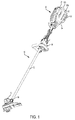
- FIG. 1 illustrates an embodiment of the string trimmer assembly 10 including an elongated support shaft assembly 12, a handle assembly 14, provided along the support shaft assembly 12, a motor assembly 16 provided generally at a distal end 18 of the support shaft assembly 12, and a protective battery housing assembly 20, provided generally at a proximal end 23 or rearward end of the support shaft assembly 12.
- the battery housing assembly 20 includes a bottom protective member, which may be a skid plate assembly 22, configured for removable engagement with the battery housing assembly 20.
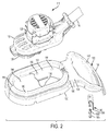
- the battery housing assembly 20 generally includes as base housing member 24 comprising housing members 24a and 24b, configured for receiving the insertion of a battery 26 therein.
- the housing members 24a and 24b are mirror images, thus for purposes of this description, all references to features on one of the housing members are also present in the other housing member.
- the base housing member 24 may also be provided as a unitary integral structure.
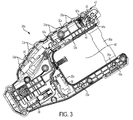
- the base housing member 24a generally includes a front end member 28a configured to receivably engage a frontal portion of the battery 26 in an inserted position.
- the base housing member 24a further includes a top member 32a, and an opposing bottom member, 34a which in cooperation define a chamber 40 configured to receive insertion of the battery 26 therein.
- the battery housing assembly 20 further includes a plurality of electrical components 98 provided therein to deliver power from the battery 26 to the motor assembly 16 and control operation of the string trimmer (see also FIGS 2 and 10 ).
- the top member 32a extends from the front end member 28a, and is configured to receivably engage a top portion of the battery 26.
- the bottom member 34a also extends from the front member 28a, and is configured to support a lower portion of the battery 26, when in an inserted position.
- the exterior portions of the bottom member 34a and top member 32a are connected by first support bracket 36a on one side of the base housing member 24a, and a second support bracket 36b, is provided on the opposite side of the base housing member 24b.
- Each respective support bracket 36a, 36b extends between the respective top member 32a, 32b and bottom member 34a, 34b, further defining the chamber 40 therein.
- the top exterior portion 30a or armrest of the top member 32a includes a composite rubber exterior configured to provide cushioning to the user's arm during use, and further is capable of absorbing an impact if the string trimmer is dropped.
- the top exterior portion 30a includes a plurality of projections 33a provided along the exterior. In the event that string trimmer is dropped or impacts a surface, the projections 33a also provide for impact absorption.
- an interior 39 of the top member 32 generally includes a latch assembly 42, and one or more groove members 46a, 46b, providing a space 47 configured to receive a top portion of the battery 26 therein, when the battery 26 is in an inserted portion.
- the latch assembly 42 is generally a spring loaded lever 43 with a detent 44, biased in a locking position.
- the detent 44 engages a portion of the battery 26, locking the battery 26 in the chamber 40.
- Groove members 46a, 46b extend along the interior top portion, providing a space to receive insertion of a rib portion of the battery 26 therein.
- the battery 26 may be released from the chamber 40, by depressing the latch 42, thus lifting the detent 44 from an engaged position with the battery 26, to an unengaged position, and sliding the battery 26 out of the chamber 40.
- the battery housing assembly 20 further includes dual side members 60a and 60b, configured to engage the base housing members 24a and 24b, forming a protective cage to for the battery 26.
- the side members 60a and 60b are mirror images. Accordingly, for purposes of discussion, all features disclosed on one of the side members also are present on the other side member.
- the side members 60a and 60b are configured for removable connection to the outer side exterior of the base housing members 24a and 24b. As shown, the side members 60a and 60b may be removably connected to the base housing members 24a and 24b with fasteners 62a and 62b, as further shown in FIG. 2 .
- the removable feature of the side members 60a, 60b allows a userto replace one or both of the side members 60a, 60b in the event of damage, without replacing the entire housing structure.
- each housing member 24a, 24b have respective openings 41a, 41b, and one or more apertures 63a, 63b formed generally about the periphery of the respective openings 41a, 41b for receiving respective fasteners 62a, 62b therein.
- the apertures 63a, 63b are formed generally about the four corners of the respective openings 41, 41b.
- each respective side member 60a, 60b also includes one or more apertures 67a, 67b configured to receive respective fasteners 62a, 62b therein, for fastening the respective side member 60a, 60b to the respective housing member 24a, 24b.
- each side member 60a, and 60b has an interior configured for engagement with a respective base housing member 24a and 24b.
- the side members 60a, 60b each include respective top foot portions 64a, 64b and a bottom foot portion 65a, 65b (not shown) extending generally inward for engagement with corresponding foot portions 69a, 71a (not shown) and 69b, 71b of the base housing members 24a, 24b.
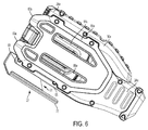
- each side member 60a, 60b has a respective abutment 58a and 58b (not shown), extending along the rear of the respective side members 60a, 60b, and defining a respective groove 59a (as shown in FIGS. 2 and 4 ) and 59b (not shown) configured to receive respective support brackets 36a, 36b of the respective base housing member 24a, 24b therein.
- each side member 60a, 60b has a respective first projection 82a, 82b provided at the end top portion of the respective side member 60a, 60b, and a second projection 83a, 83b provided at the end bottom portion of the side member 60a, 60b.
- first projection 82b and second projection 83b extends beyond the outer edge of the base housing members 24b, providing protection to the rear portion of the connected battery 26.
- the respective side members 60a, 60b further include one or more apertures 84, 86 formed therein.
- the respective apertures 84, 86 reduce the weight of the side members 60a, 60b, and further permit a user to view the battery 26, inserted therein.
- the skid plate assembly 22 is removably attachable to the base housing member 24.
- the bottom exterior portion 66 of the base housing member 24 provides a base member68 extending therefrom.
- the base member 68b provides a base for receiving removable connection of the skid plate assembly 22.
- the skid plate assembly 22 in a connected state, forms a generally U-shaped configuration with the base housing member 24, providing a space 51 therebetween.
- the skid plate assembly 22 includes a first base portion 70, a second extension base portion 76 and a third mounting portion 78.
- the skid plate assembly 22 is comprised of a generally flexible composite plastic material conducive for absorbing an impact, such as Xenoy, for example.
- the first portion 70 of the skid plate assembly 22 extends generally parallel to the bottom exterior portion 66 of the base housing members 24a and 24b, permitting secure operative engagement thereto.
- the first portion 70 provides a base to support the base housing members 24a and 24b.
- the first portion 70 includes a series of apertures 72a and 72b, formed therein.
- the apertures 72a and 72b are configured to receive respective plural fasteners 74a and 74b, to securely fasten the skid plate assembly 22 to the bottom exterior portion 66, which is formed the combination of the housing members 24a and 24b.
- the second portion 76 of the skid plate assembly 22 extends generally perpendicularly upward from the first portion 70 to operatively engage a back portion of the base housing portion 24.
- the second portion 76 in cooperation with the second projections 83a, 83b of the respective side members 60a, 60b provide enhanced protection to the back portion of the battery 26
- the third mounting portion 78 of the skid plate assembly 22 has a generally flat configuration, which permits the skid plate assembly 22, and the housing assembly 20to be placed on an adjacent surface, for example the ground, as illustrated in FIG. 8 .
- the third portion 78 of the skid plate assembly 22 extends in a generally parallel manner relative to the bottom exterior portion 66 of the base housing portion 24. As such, in a rested position, the skid plate assembly 22 engages the adjacent surface and spaces the handle assembly 14 from contact with the adjacent surface. This protects the handle assembly 14 from potential damage from the adjacent surface when the string trimmer 10 is in a rested position.
- the third portion 78 of the skid plate assembly 22 and the bottom portion 66 of the base housing portion 24 form a space 51 therebetween, permitting the string trimmer 10 to be hung vertically from the skid plate assembly 22 on a hook or upright surface.
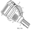
- FIGS. 11A and 11B show an alternate embodiment of the armrest provided on the string trimmer 120, where instead of having projections, a single pad 130 is provided to permit compression when in contact with the user's arm.
- the pad 130 is provided on the exterior of a top member 132 of a housing member 124.
- the pad is cored out with a plurality of generally hollow cushion members 195, which may have a triangular configuration.
- a battery 126 may be provided on the rear portion of the housing member 124.
- the pad 130 is provided along the exterior portion of the top member 132 such that when a user's arm engages the pad 130, the cushion members 195 compress, absorbing contact with the user's arm, thus providing a soft feel to the user.
- the pad 130 may be manufactured with the housing member 124 by overmold tooling as an integral member.
Landscapes
- Life Sciences & Earth Sciences (AREA)
- Environmental Sciences (AREA)
- Chemical & Material Sciences (AREA)
- Chemical Kinetics & Catalysis (AREA)
- Electrochemistry (AREA)
- General Chemical & Material Sciences (AREA)
- Engineering & Computer Science (AREA)
- Mechanical Engineering (AREA)
- Battery Mounting, Suspending (AREA)
Abstract
Description
- The present invention relates to a battery-powered string trimmer. More particularly, the invention relates to a battery-powered string trimmer having a battery housing assembly, configured to protect the battery from impacts and permit easy storage.
- Conventional string trimmers are generally used for horizontal trimming and vertical edging of lawn. Typically, string trimmers include a handle, a motor, a power source, and an elongated shaft and a lower cutting head from which the string cutting element extends and rotates to cut grass, weeds, and other vegetation. String trimmers may be powered by combustible fuel engines or electric motors. The versions driven by electric motors may be connected to a line source such as 120 volt alternating current electric power, or they may be powered by a battery pack or other source of direct current electrical power.
- Most battery-powered string trimmers conventionally have a motor provided at a lower end of the elongated shaft and are actuated by a trigger provided in the handle assembly. Some conventional battery-powered string trimmers provide the battery in conjunction with the handle assembly, as a unitary system, while other string trimmers provide the battery at the opposing end portion of the elongated support shaft. In both of these configurations, the battery and/or housing is susceptible to damage if dropped on a surface.
- In general, batteries used to power handheld devices, such as the string trimmer, are relatively heavy, as well as expensive. As such, during operation, the overall weight of the battery may on occasion cause the user to accidentally drop the battery end of the string trimmer, causing the battery housing to forcibly impact a surrounding surface. The overall weight of the battery, and thus force of the impact, may cause damage to the housing of the string trimmer, and/or to the battery itself.
- Most string trimmers on the market do not provide a battery housing assembly configured to adequately protect the battery, and withstand a forceful impact with a hard surface, such as the ground or concrete. Further, most battery housing assemblies do not provide a battery housing assembly that facilitate the string trimmer to be mounted or stored in generally horizontal, as well as vertical position.
- According to one aspect of the invention, there is provided a battery housing assembly for an outdoor power tool, comprising:
- a base housing member defining a chamber configured to receive a battery therein, the base housing member including a frontal member configured to engage a front portion of the battery, a top member and a bottom member extending from the frontal member;
- a first side member configured to be removably connected to a first side of the base housing member; and,
- a second side member configured to be removably connected to an opposing second side of the base housing member,
- In one arrangement, the top member of the base housing member may include a first groove member and a second groove member configured to engage a top portion of the battery therein to facilitate fastening of the battery within the base housing member.
- The top member of the base housing member may provide a latch member configured to selectively engage a top portion of an inserted battery to facilitate securing the battery within the battery housing.
- Furthermore, the exterior of the top portion of the base housing member may include a composite rubber adapted to support a user's forearm when in use.
- In addition the first side member and second side member are comprised of a resilient material to absorb impacts.
- There may also be provided a support bracket on both the first side and second side of the base housing member, the first and second support brackets connecting the top member and the bottom member, wherein the first and second side members may include a groove for receiving a support bracket.
- Advantageously, each side member has at least one projection extending beyond the rear boundary of the base housing portion. There may also be provided a skid plate assembly connected to the base housing member. The skid plate assembly may include a base portion and an extension portion, the extension portion possibly extending upwardly from the base portion to partially shield the rear of the battery housing assembly.
- Furthermore, the skid plate assembly may form a cavity with the base housing member.
- Each side member may have at least one projection extending beyond the rear boundary of the base housing portion, wherein the extension portion of the skid plate assembly and the at least one projection may cooperatively protect a back portion of the battery.
- The skid plate assembly may form a generally U-shaped configuration with the base housing member to provide a hook for hanging the outdoor power tool.
- The skid plate assembly may have a resilient body configured to absorb an impact. In a further aspect there is provided an outdoor powertool having the battery housing assembly as described above.
The first and second side members may be removable from the base housing member.
The battery housing assembly may further include a first support bracket on the first side of the base housing member and a second support bracket on the second side of the housing member, wherein the first side member are secured to the first support bracket and the second side member is secured to the second support bracket. - The top member may include a resilient outer surface to provide a forearm support surface.
- In a further aspect of the invention, there is provided an outdoor power tool having battery housing assembly comprising:
- a base housing member defining a chamber configured to receive a battery therein, the base housing member including a frontal member configured to engage a front of the battery, a top member and a top member extending from the frontal member;
- a first side member on a first side of the base housing member and a second side member on a second side of the base housing member,
- wherein a rear portion of the battery housing assembly is open for receiving the battery.
- Further, projections may extend rearwardly from one or more of the top, bottom or side members so that the projections extend beyond the battery
- In one arrangement there may be provided a skid plate assembly including a base member and an extension portion, the extension portion extending upwardly from the base portion to partially shield a rear opening of the battery housing assembly.
- The skid plate assembly may form a generally U-shaped configuration with the base housing member to provide a hook for hanging the string trimmer. In addition wherein the skid plate assembly may have a resilient body configured to absorb an impact.
- In one embodiment, wherein the first and second side members are removable from the base housing member.
- In another embodiment, a first support bracket on the first side of the base housing member and a second support bracket on the second side of the housing member,
wherein the first side member are secured to the first support bracket and the second side member is secured to the second support bracket.
The top member may include a resilient outer surface to provide a forearm support surface. - In order to better understand various exemplary embodiments, reference is made to the accompanying drawings, wherein:
-
FIG. 1 is an environmental perspective view of a string trimmer having a protective battery housing assembly with a skid plate assembly attached thereto; -
FIG. 2 is an exploded perspective view of the battery housing assembly ofFIG.1 , illustrating the side members of the battery housing assembly in an unattached position; -
FIG. 3 is an interior sectional side view of a base housing member of the interior battery housing assembly ofFIG. 1 ; -
FIG. 4 is an interior side view of an exemplary side member ofFIG. 2 ; -
FIG. 5 is a perspective view of the battery housing assembly ofFIG. 1 , with the skid plate assembly attached thereto; -
FIG. 6 is side view of the battery housing assembly ofFIG. 1 , with the skid plate assembly attached thereto; -
FIG. 7 is a top view of the battery housing assembly ofFIG. 1 ; -
FIG. 8 is side view of the string trimmer assembly ofFIG. 1 , in a generally horizontally mounted position, illustrating battery housing assembly and skid plate assembly engaged with a generally flat surface; -
FIG. 9A is a rear perspective view of the string trimmer battery housing assembly with the battery provided therein; -
FIG. 9B is a rear perspective view of the string trimmer battery housing assembly illustrating a chamber for receiving a battery; -
FIG. 10 is a side perspective sectional view of the battery housing assembly; -
FIG. 11A is side perspective view of an embodiment of the battery housing assembly, illustrating an armrest for providing a soft feel to the user when in contact with the battery housing; and, -
FIG. 11B is a side sectional view of the battery housing assembly ofFIG. 11A . - To facilitate understanding, identical reference numerals have been used to designate elements having substantially the same or similar structure and/or substantially the same or similar function.
- Most string trimmers are configured with an elongated shaft configuration. The elongated configuration has several key components provided across an extended distance, which makes it difficult for a user to fully protect the components at all times. For example, components at the end of the string trimmer opposite the cutting head, such as the battery, may extend beyond the user's body resulting in a greater chance that those components may strike obstacles resulting in damage. Also, damage may occur when the string trimmer is dropped. The elongated configuration of the shaft of the string trimmer also limits the options to mount or store the string trimmer after use. Further, most string trimmer batteries are relatively heavy and expensive and would be damaged in the event of a large impact.
- Accordingly, it is desirable to provide a string trimmer assembly having a protective battery housing assembly configured to protect the battery from impact. It is further desirable to provide a removably attachable skid plate, configured to provide a buffer for the string trimmer when stored in a horizontal manner, and a hook permitting the string trimmer to be hung in a vertical manner.
- The foregoing advantages of the invention are illustrative of those that can be achieved by the various exemplary embodiments and are not intended to be exhaustive or limiting of the possible advantages which can be realized. Thus, these and other advantages of the various exemplary embodiments will be apparent from the description herein or can be learned from practicing the various exemplary embodiments, both as embodied herein or as modified in view of any variation that may be apparent to those skilled in the art. Accordingly, the present invention resides in the novel methods, arrangements, combinations, and improvements herein shown and described in various exemplary embodiments.
- The battery housing assembly and skid plate assembly for the string trimmer, are configured to securely encase a conventional battery unit, protecting the battery unit from impact in the event of being dropped. Referring now to the drawings, wherein the illustrations are for purposes of describing one or more embodiments and not for the purposes of limiting the same,
FIG. 1 illustrates an embodiment of thestring trimmer assembly 10 including an elongatedsupport shaft assembly 12, ahandle assembly 14, provided along thesupport shaft assembly 12, amotor assembly 16 provided generally at adistal end 18 of thesupport shaft assembly 12, and a protectivebattery housing assembly 20, provided generally at aproximal end 23 or rearward end of thesupport shaft assembly 12. As shown, thebattery housing assembly 20 includes a bottom protective member, which may be askid plate assembly 22, configured for removable engagement with thebattery housing assembly 20. - As shown in
FIG. 2 , thebattery housing assembly 20 generally includes asbase housing member 24 comprisinghousing members 24a and 24b, configured for receiving the insertion of abattery 26 therein. Notably, thehousing members 24a and 24b are mirror images, thus for purposes of this description, all references to features on one of the housing members are also present in the other housing member. Alternatively, thebase housing member 24 may also be provided as a unitary integral structure. - As shown in
FIG. 3 , thebase housing member 24a generally includes afront end member 28a configured to receivably engage a frontal portion of thebattery 26 in an inserted position. Thebase housing member 24a further includes atop member 32a, and an opposing bottom member, 34a which in cooperation define achamber 40 configured to receive insertion of thebattery 26 therein. Thebattery housing assembly 20 further includes a plurality ofelectrical components 98 provided therein to deliver power from thebattery 26 to themotor assembly 16 and control operation of the string trimmer (see alsoFIGS 2 and10 ). - The
top member 32a extends from thefront end member 28a, and is configured to receivably engage a top portion of thebattery 26. Thebottom member 34a also extends from thefront member 28a, and is configured to support a lower portion of thebattery 26, when in an inserted position. As shown, the exterior portions of thebottom member 34a andtop member 32a are connected byfirst support bracket 36a on one side of thebase housing member 24a, and a second support bracket 36b, is provided on the opposite side of the base housing member 24b. Eachrespective support bracket 36a, 36b extends between the respectivetop member 32a, 32b andbottom member 34a, 34b, further defining thechamber 40 therein. - As shown, the top
exterior portion 30a or armrest of thetop member 32a includes a composite rubber exterior configured to provide cushioning to the user's arm during use, and further is capable of absorbing an impact if the string trimmer is dropped. The topexterior portion 30a includes a plurality ofprojections 33a provided along the exterior. In the event that string trimmer is dropped or impacts a surface, theprojections 33a also provide for impact absorption. - As shown in
FIGS. 9A and9B , an interior 39 of thetop member 32 generally includes alatch assembly 42, and one ormore groove members space 47 configured to receive a top portion of thebattery 26 therein, when thebattery 26 is in an inserted portion. As shown, thelatch assembly 42 is generally a spring loadedlever 43 with adetent 44, biased in a locking position. - In an inserted position, the
detent 44 engages a portion of thebattery 26, locking thebattery 26 in thechamber 40.Groove members battery 26 therein. In an inserted position, thebattery 26 may be released from thechamber 40, by depressing thelatch 42, thus lifting thedetent 44 from an engaged position with thebattery 26, to an unengaged position, and sliding thebattery 26 out of thechamber 40. - Referring now to
FIG. 2 , thebattery housing assembly 20 further includesdual side members base housing members 24a and 24b, forming a protective cage to for thebattery 26. Notably, theside members side members base housing members 24a and 24b. As shown, theside members base housing members 24a and 24b with fasteners 62a and 62b, as further shown inFIG. 2 . The removable feature of theside members side members - As further illustrated in
FIGS. 2 and3 , eachhousing member 24a, 24b have respective openings 41a, 41b, and one ormore apertures 63a, 63b formed generally about the periphery of the respective openings 41a, 41b for receiving respective fasteners 62a, 62b therein. In this example, theapertures 63a, 63b are formed generally about the four corners of the respective openings 41, 41b. Additionally, eachrespective side member more apertures 67a, 67b configured to receive respective fasteners 62a, 62b therein, for fastening therespective side member respective housing member 24a, 24b. - As further shown, each
side member base housing member 24a and 24b. Theside members top foot portions 64a, 64b and abottom foot portion 65a, 65b (not shown) extending generally inward for engagement with corresponding foot portions 69a, 71a (not shown) and 69b, 71b of thebase housing members 24a, 24b. Further, eachside member respective abutment 58a and 58b (not shown), extending along the rear of therespective side members respective groove 59a (as shown inFIGS. 2 and4 ) and 59b (not shown) configured to receiverespective support brackets 36a, 36b of the respectivebase housing member 24a, 24b therein. - Further, each
side member first projection respective side member second projection side member FIG. 5 , in a connected position, thefirst projection 82b andsecond projection 83b extends beyond the outer edge of the base housing members 24b, providing protection to the rear portion of the connectedbattery 26. - The
respective side members side members battery 26, inserted therein.
As further shown inFIGS. 5-8 , theskid plate assembly 22 is removably attachable to thebase housing member 24. Thebottom exterior portion 66 of thebase housing member 24 provides a base member68 extending therefrom. The base member 68b provides a base for receiving removable connection of theskid plate assembly 22. As shown, theskid plate assembly 22, in a connected state, forms a generally U-shaped configuration with thebase housing member 24, providing aspace 51 therebetween. - As shown in
FIG. 2 , theskid plate assembly 22 includes a first base portion 70, a second extension base portion 76 and a third mountingportion 78. Theskid plate assembly 22 is comprised of a generally flexible composite plastic material conducive for absorbing an impact, such as Xenoy, for example. The first portion 70 of theskid plate assembly 22 extends generally parallel to thebottom exterior portion 66 of thebase housing members 24a and 24b, permitting secure operative engagement thereto. The first portion 70 provides a base to support thebase housing members 24a and 24b. The first portion 70 includes a series of apertures 72a and 72b, formed therein. The apertures 72a and 72b are configured to receive respective plural fasteners 74a and 74b, to securely fasten theskid plate assembly 22 to thebottom exterior portion 66, which is formed the combination of thehousing members 24a and 24b. - The second portion 76 of the
skid plate assembly 22 extends generally perpendicularly upward from the first portion 70 to operatively engage a back portion of thebase housing portion 24. As such, the second portion 76, in cooperation with thesecond projections respective side members battery 26 - As shown in
FIG. 6 , the third mountingportion 78 of theskid plate assembly 22 has a generally flat configuration, which permits theskid plate assembly 22, and the housing assembly 20to be placed on an adjacent surface, for example the ground, as illustrated inFIG. 8 . Thethird portion 78 of theskid plate assembly 22 extends in a generally parallel manner relative to thebottom exterior portion 66 of thebase housing portion 24. As such, in a rested position, theskid plate assembly 22 engages the adjacent surface and spaces thehandle assembly 14 from contact with the adjacent surface. This protects thehandle assembly 14 from potential damage from the adjacent surface when thestring trimmer 10 is in a rested position. - Additionally, the
third portion 78 of theskid plate assembly 22 and thebottom portion 66 of thebase housing portion 24 form aspace 51 therebetween, permitting thestring trimmer 10 to be hung vertically from theskid plate assembly 22 on a hook or upright surface. -
FIGS. 11A and11B show an alternate embodiment of the armrest provided on thestring trimmer 120, where instead of having projections, asingle pad 130 is provided to permit compression when in contact with the user's arm. As illustrated thepad 130 is provided on the exterior of atop member 132 of ahousing member 124. The pad is cored out with a plurality of generallyhollow cushion members 195, which may have a triangular configuration. Abattery 126 may be provided on the rear portion of thehousing member 124. - The
pad 130 is provided along the exterior portion of thetop member 132 such that when a user's arm engages thepad 130, thecushion members 195 compress, absorbing contact with the user's arm, thus providing a soft feel to the user. Thepad 130 may be manufactured with thehousing member 124 by overmold tooling as an integral member.
Although the various exemplary embodiments have been described in detail with particular reference to certain exemplary aspects thereof, it should be understood that the invention is capable of other embodiments and its details are capable of modifications in various obvious respects. As is readily apparent to those skilled in the art, variations and modifications can be affected while remaining within the spirit and scope of the invention. Accordingly, the foregoing disclosure, description, and figures are for illustrative purposes only and do not in any way limit the invention, which is defined only by the claims.
Claims (14)
- A battery housing assembly for an outdoor power tool, comprising:a base housing member defining a chamber configured to receive a battery therein, the base housing member including a frontal member configured to engage a front portion of the battery, a top member and a bottom member extending from the frontal member;a first side member configured to be removably connected to a first side of the base housing member; and,a second side member configured to be removably connected to an opposing second side of the base housing member,wherein the first side member and second side member in cooperation with the base housing member define a chamber to receive the battery therein and provide protection to the battery.
- The battery housing assembly of claim 1, wherein the top member of the base housing member includes a first groove member and a second groove member configured to engage a top portion of the battery therein to facilitate fastening of the battery within the base housing member.
- The battery housing assembly of claim 1, wherein the top member of the base housing member provides a latch member configured to selectively engage a top portion of an inserted battery to facilitate securing the battery within the battery housing.
- The battery housing assembly as claimed in any preceding claim, wherein the exterior of the top portion of the base housing member includes a composite rubber adapted to support a user's forearm when in use.
- The battery housing assembly as claimed in any preceding claim, wherein the first side member and second side member are comprised of a resilient material to absorb impacts.
- The battery housing assembly as claimed in any preceding claim, further including a support bracket on both the first side and second side of the base housing member, the first and second support brackets connecting the top member and the bottom member, wherein the first and second side members include a groove for receiving a support bracket.
- The battery housing assembly as claimed in any preceding claim, wherein each side member has at least one projection extending beyond the rear boundary of the base housing portion.
- The battery housing assembly as claimed in any preceding claim, further comprising a skid plate assembly connected to the base housing member.
- The battery housing assembly of claim 8, wherein the skid plate assembly includes a base portion and an extension portion, the extension portion extending upwardly from the base portion to partially shield the rear of the battery housing assembly.
- The battery housing assembly as claimed in claim 8 or claim 9, wherein the skid plate assembly forms a cavity with the base housing member.
- The battery housing assembly as claimed in any one of claims 8 to 10, wherein each side member has at least one projection extending beyond the rear boundary of the base housing portion, wherein the extension portion of the skid plate assembly and the at least one projection cooperatively protect a back portion of the battery.
- The battery housing assembly as claimed in any one of claims 8 to 11, wherein the skid plate assembly forms a generally U-shaped configuration with the base housing member to provide a hook for hanging the outdoor power tool.
- The battery housing assembly as claimed in any of the claims 8 to 12, wherein the skid plate assembly has a resilient body configured to absorb an impact.
- An outdoor power tool having the battery housing assembly of any preceding claim.
Applications Claiming Priority (1)
| Application Number | Priority Date | Filing Date | Title |
|---|---|---|---|
| US14/713,411 US10224524B2 (en) | 2015-05-15 | 2015-05-15 | String trimmer battery housing assembly |
Publications (2)
| Publication Number | Publication Date |
|---|---|
| EP3093902A1 true EP3093902A1 (en) | 2016-11-16 |
| EP3093902B1 EP3093902B1 (en) | 2018-12-12 |
Family
ID=56096452
Family Applications (1)
| Application Number | Title | Priority Date | Filing Date |
|---|---|---|---|
| EP16169032.6A Active EP3093902B1 (en) | 2015-05-15 | 2016-05-10 | String trimmer battery housing assembley |
Country Status (3)
| Country | Link |
|---|---|
| US (2) | US10224524B2 (en) |
| EP (1) | EP3093902B1 (en) |
| CN (1) | CN205900615U (en) |
Cited By (1)
| Publication number | Priority date | Publication date | Assignee | Title |
|---|---|---|---|---|
| DE102020118243A1 (en) | 2020-07-10 | 2022-01-13 | J. Wagner Gmbh | Hand tool and hand tool system |
Families Citing this family (24)
| Publication number | Priority date | Publication date | Assignee | Title |
|---|---|---|---|---|
| USD787285S1 (en) * | 2014-12-18 | 2017-05-23 | Black & Decker Inc. | String trimmer |
| US9854738B2 (en) | 2015-05-15 | 2018-01-02 | Black & Decker, Inc. | String trimmer with adjustable guard assembly |
| US10500754B2 (en) * | 2016-01-14 | 2019-12-10 | Echo Incorporated | Battery operated chain saw unit and method of constructing the same |
| US10656679B2 (en) * | 2016-01-16 | 2020-05-19 | Jsc Yukon Advanced Optics Worldwide | Securely mounting electronic device battery pack |
| USD813621S1 (en) * | 2016-06-20 | 2018-03-27 | Black & Decker Inc. | String trimmer |
| USD828125S1 (en) * | 2017-01-31 | 2018-09-11 | The Toro Company | Handle for lawn and garden tool |
| USD832669S1 (en) | 2017-04-25 | 2018-11-06 | The Toro Company | Handle for lawn and garden tool |
| US10888987B2 (en) * | 2017-05-04 | 2021-01-12 | Skitter & Squirt Adventures, Llc | Power tool ski system and method |
| CN107240661B (en) * | 2017-07-25 | 2023-06-16 | 天佑电器(苏州)有限公司 | Battery pack and gardening tool |
| USD874891S1 (en) | 2017-08-04 | 2020-02-11 | Husqvarna Ab | Guard shield for a trimmer |
| USD889219S1 (en) * | 2017-08-04 | 2020-07-07 | Husqvarna Ab | Air outlet for a trimmer |
| EP3701782B1 (en) * | 2017-10-24 | 2025-06-25 | Suzhou Cleva Precision Machinery & Technology Co., Ltd. | Handle assembly and gardening tool having same |
| USD919387S1 (en) * | 2018-09-18 | 2021-05-18 | Andreas Stihl Ag & Co. Kg | Battery powered hedge trimmer |
| CN110352693B (en) * | 2019-06-27 | 2022-04-15 | 宁波奥晟机械有限公司 | Portable electric brush cutter |
| USD960670S1 (en) | 2019-12-27 | 2022-08-16 | The Toro Company | Handle for lawn and garden tool |
| EP4167713A4 (en) | 2020-06-19 | 2024-09-11 | Milwaukee Electric Tool Corporation | THREAD CUTTER |
| CN217742287U (en) * | 2021-04-12 | 2022-11-08 | 南京泉峰科技有限公司 | Grass trimmer |
| TWI823790B (en) * | 2023-03-03 | 2023-11-21 | 炬岱企業有限公司 | Power tool battery plug-in structure |
| EP4501096A3 (en) * | 2023-08-04 | 2025-11-12 | Milwaukee Electric Tool Corporation | String trimmers |
| USD1074345S1 (en) * | 2023-09-07 | 2025-05-13 | Greenworks (Jiangsu) Co., Ltd | Lawn trimmer |
| USD1116659S1 (en) * | 2024-03-26 | 2026-03-10 | Westinghouse Electric & Manufacturing Company | String trimmer |
| DE102024112209A1 (en) * | 2024-04-30 | 2025-10-30 | Andreas Stihl Ag & Co. Kg | Tool with a shaft and a battery pack |
| DE102024116787A1 (en) * | 2024-06-14 | 2025-12-18 | Andreas Stihl Ag & Co. Kg | TOOL AND PROTECTIVE ELEMENT FOR A PORTABLE TOOL |
| DE102024116785A1 (en) * | 2024-06-14 | 2025-12-18 | Andreas Stihl Ag & Co. Kg | TOOL AND HOUSING PART FOR A PORTABLE TOOL |
Citations (3)
| Publication number | Priority date | Publication date | Assignee | Title |
|---|---|---|---|---|
| EP1025961A1 (en) * | 1999-01-29 | 2000-08-09 | Black & Decker Inc. | Battery powered hand guided power tool |
| GB2430342A (en) * | 2005-09-23 | 2007-03-28 | Positec Power Tools | Line trimmer having handle arrangement |
| US20080032190A1 (en) * | 2006-08-04 | 2008-02-07 | Makita Corporation | Power tool and protector for power tool |
Family Cites Families (32)
| Publication number | Priority date | Publication date | Assignee | Title |
|---|---|---|---|---|
| US286259A (en) | 1883-10-09 | Process | ||
| US4014129A (en) | 1975-03-26 | 1977-03-29 | Theodore Capra | Fishing rod stabilizing handle |
| US4540943A (en) | 1981-10-06 | 1985-09-10 | Akers Oliver C | Belt-supported swingable metal detector |
| CA1224022A (en) | 1983-11-10 | 1987-07-14 | William J. O'brien | Electric knife |
| US5313735A (en) | 1992-03-02 | 1994-05-24 | Latouche Desmond J | Rotatable handle extension for fishing rods and the like |
| USD352430S (en) | 1993-01-29 | 1994-11-15 | Ryobi Outdoor Products Inc. | Power head for a line trimmer |
| US5265341A (en) * | 1993-01-29 | 1993-11-30 | Pyobi Outdoor Products, Inc. | Battery powered line trimmer arm rest |
| US5661960A (en) | 1995-09-07 | 1997-09-02 | Smith; Walker | Power tool arm engaging assembly and wheeled platform for a line trimmer |
| US5809614A (en) | 1996-12-03 | 1998-09-22 | Kretser, Jr.; Karl D. | Pivoting forearm cradle for weed trimming device |
| US5802960A (en) | 1997-11-26 | 1998-09-08 | Graj & Gustavsen | Ergonomic cookware |
| US20020041987A1 (en) | 1998-10-23 | 2002-04-11 | Joseph H. Schulman | Prismatic zincair battery for use with biological stimulator |
| US6181032B1 (en) * | 1999-07-14 | 2001-01-30 | Black & Decker Inc. | Releasably connecting power packs to electrical appliances |
| DE10003984A1 (en) | 2000-01-29 | 2001-08-02 | Stihl Maschf Andreas | Tool with a drive motor |
| US20040007887A1 (en) | 2000-06-29 | 2004-01-15 | Elliott Olin L. | Extendable handle for a manually operated implement and method |
| US6598266B1 (en) | 2000-06-29 | 2003-07-29 | Olin S. Elliott | Handle for a manually operated implement and method |
| US7373817B2 (en) * | 2004-07-09 | 2008-05-20 | Touchsensor Technologies, Llc | Solid state fluid level sensor |
| DE102004044331B4 (en) * | 2004-09-09 | 2019-05-09 | Robert Bosch Gmbh | Device for locking an electrical appliance with an accessory |
| US20060123635A1 (en) | 2004-12-09 | 2006-06-15 | Heow, Inc. | Combination blower, trimmer and edger for tending vegetation |
| USD533792S1 (en) | 2005-07-15 | 2006-12-19 | Garrett Electronics, Inc. | Metal detector |
| US20080134552A1 (en) | 2006-12-08 | 2008-06-12 | Lough Pamela M | Garment display window and related method |
| DE102007023391B4 (en) | 2007-05-18 | 2019-05-02 | Dr. Ing. H.C. F. Porsche Aktiengesellschaft | Protective housing for a vehicle battery and motor vehicle with such a protective housing |
| JP5750825B2 (en) * | 2009-08-28 | 2015-07-22 | 日立工機株式会社 | Electric working machine |
| WO2012002860A1 (en) | 2010-07-02 | 2012-01-05 | Husqvarna Ab | Battery powered tool |
| US9414540B2 (en) | 2010-03-24 | 2016-08-16 | Aero-Flex Technologies, Inc. | Oriented trimmer line |
| DE102010013756A1 (en) | 2010-03-31 | 2011-10-06 | Andreas Stihl Ag & Co. Kg | Hand-held implement |
| JP5587801B2 (en) * | 2010-09-13 | 2014-09-10 | 株式会社マキタ | Rechargeable power tool |
| DE102010045994A1 (en) | 2010-09-18 | 2012-03-22 | Andreas Stihl Ag & Co. Kg | Hand-held implement |
| US20120180445A1 (en) | 2011-01-14 | 2012-07-19 | Edward Duller | Lawn edger |
| TWM417591U (en) * | 2011-07-13 | 2011-12-01 | Wistron Corp | Portable electronic device and battery module withdrawing structure with foot pad function |
| US9190644B2 (en) * | 2011-12-21 | 2015-11-17 | Echo, Inc. | Staging system for battery on a portable tool |
| US9472992B2 (en) * | 2013-07-11 | 2016-10-18 | The Toro Company | Electric motor support structure and power equipment unit incorporating same |
| USD710161S1 (en) | 2013-09-18 | 2014-08-05 | Sears Brands, L.L.C. | String trimmer |
-
2015
- 2015-05-15 US US14/713,411 patent/US10224524B2/en active Active
-
2016
- 2016-04-29 CN CN201620383160.3U patent/CN205900615U/en not_active Expired - Fee Related
- 2016-05-10 EP EP16169032.6A patent/EP3093902B1/en active Active
-
2019
- 2019-01-16 US US16/249,399 patent/US11024916B2/en active Active
Patent Citations (3)
| Publication number | Priority date | Publication date | Assignee | Title |
|---|---|---|---|---|
| EP1025961A1 (en) * | 1999-01-29 | 2000-08-09 | Black & Decker Inc. | Battery powered hand guided power tool |
| GB2430342A (en) * | 2005-09-23 | 2007-03-28 | Positec Power Tools | Line trimmer having handle arrangement |
| US20080032190A1 (en) * | 2006-08-04 | 2008-02-07 | Makita Corporation | Power tool and protector for power tool |
Cited By (2)
| Publication number | Priority date | Publication date | Assignee | Title |
|---|---|---|---|---|
| DE102020118243A1 (en) | 2020-07-10 | 2022-01-13 | J. Wagner Gmbh | Hand tool and hand tool system |
| US12478996B2 (en) | 2020-07-10 | 2025-11-25 | J. Wagner Gmbh | Spraying device and portable power tool system |
Also Published As
| Publication number | Publication date |
|---|---|
| US10224524B2 (en) | 2019-03-05 |
| EP3093902B1 (en) | 2018-12-12 |
| US11024916B2 (en) | 2021-06-01 |
| US20160336557A1 (en) | 2016-11-17 |
| US20190148684A1 (en) | 2019-05-16 |
| CN205900615U (en) | 2017-01-18 |
Similar Documents
| Publication | Publication Date | Title |
|---|---|---|
| EP3093902B1 (en) | String trimmer battery housing assembley | |
| US3729912A (en) | Snap on shroud mounting | |
| RU2578479C2 (en) | Electric lawn mower (versions) | |
| JP6315541B2 (en) | Brush cutter | |
| RU2581485C2 (en) | Electric lawnmowers | |
| US8935907B2 (en) | Electric lawn mowers | |
| JP5766547B2 (en) | Rechargeable tiller | |
| JP2010201612A (en) | Electric work machine with battery pack | |
| CN205431051U (en) | Lawn mower | |
| JP6345523B2 (en) | Battery powered work machine | |
| JP7570219B2 (en) | Hedge trimmer | |
| KR20160149124A (en) | Shock absorbtive safety blade unit for brush cutter | |
| KR20130004518A (en) | Power tool | |
| USD1003950S1 (en) | Motor housing for grass cutter | |
| US8037669B2 (en) | Baffle based battery housing | |
| JP6762194B2 (en) | Backpack type power supply system | |
| CN209949873U (en) | Lawn mower with safeguard function | |
| CN216218791U (en) | Grass trimmer, cleaning tool and electric tool | |
| JP6568418B2 (en) | Extension handle for handheld rechargeable power tools | |
| EP2982481B1 (en) | Power head for a portable handheld tool | |
| JP6914755B2 (en) | Gardening clippers | |
| KR20150135677A (en) | Bush cutting machine | |
| CN106508290B (en) | A garden tool with a battery pack | |
| KR101881152B1 (en) | Shock absorbtive safety blade unit for brush cutter | |
| JP2016029910A (en) | Hand-held lawn mower and edge mowing guide |
Legal Events
| Date | Code | Title | Description |
|---|---|---|---|
| PUAI | Public reference made under article 153(3) epc to a published international application that has entered the european phase |
Free format text: ORIGINAL CODE: 0009012 |
|
| AK | Designated contracting states |
Kind code of ref document: A1 Designated state(s): AL AT BE BG CH CY CZ DE DK EE ES FI FR GB GR HR HU IE IS IT LI LT LU LV MC MK MT NL NO PL PT RO RS SE SI SK SM TR |
|
| AX | Request for extension of the european patent |
Extension state: BA ME |
|
| STAA | Information on the status of an ep patent application or granted ep patent |
Free format text: STATUS: REQUEST FOR EXAMINATION WAS MADE |
|
| 17P | Request for examination filed |
Effective date: 20170515 |
|
| RBV | Designated contracting states (corrected) |
Designated state(s): AL AT BE BG CH CY CZ DE DK EE ES FI FR GB GR HR HU IE IS IT LI LT LU LV MC MK MT NL NO PL PT RO RS SE SI SK SM TR |
|
| STAA | Information on the status of an ep patent application or granted ep patent |
Free format text: STATUS: EXAMINATION IS IN PROGRESS |
|
| 17Q | First examination report despatched |
Effective date: 20171211 |
|
| GRAP | Despatch of communication of intention to grant a patent |
Free format text: ORIGINAL CODE: EPIDOSNIGR1 |
|
| STAA | Information on the status of an ep patent application or granted ep patent |
Free format text: STATUS: GRANT OF PATENT IS INTENDED |
|
| RIC1 | Information provided on ipc code assigned before grant |
Ipc: H01M 2/10 20060101AFI20180709BHEP Ipc: A01D 34/82 20060101ALI20180709BHEP Ipc: A01D 34/416 20060101ALI20180709BHEP Ipc: B25F 5/00 20060101ALI20180709BHEP Ipc: A01D 34/78 20060101ALI20180709BHEP |
|
| INTG | Intention to grant announced |
Effective date: 20180727 |
|
| GRAS | Grant fee paid |
Free format text: ORIGINAL CODE: EPIDOSNIGR3 |
|
| GRAA | (expected) grant |
Free format text: ORIGINAL CODE: 0009210 |
|
| STAA | Information on the status of an ep patent application or granted ep patent |
Free format text: STATUS: THE PATENT HAS BEEN GRANTED |
|
| AK | Designated contracting states |
Kind code of ref document: B1 Designated state(s): AL AT BE BG CH CY CZ DE DK EE ES FI FR GB GR HR HU IE IS IT LI LT LU LV MC MK MT NL NO PL PT RO RS SE SI SK SM TR |
|
| REG | Reference to a national code |
Ref country code: GB Ref legal event code: FG4D |
|
| REG | Reference to a national code |
Ref country code: CH Ref legal event code: EP |
|
| REG | Reference to a national code |
Ref country code: AT Ref legal event code: REF Ref document number: 1077161 Country of ref document: AT Kind code of ref document: T Effective date: 20181215 |
|
| REG | Reference to a national code |
Ref country code: DE Ref legal event code: R096 Ref document number: 602016007979 Country of ref document: DE |
|
| REG | Reference to a national code |
Ref country code: IE Ref legal event code: FG4D |
|
| REG | Reference to a national code |
Ref country code: NL Ref legal event code: MP Effective date: 20181212 |
|
| REG | Reference to a national code |
Ref country code: LT Ref legal event code: MG4D |
|
| PG25 | Lapsed in a contracting state [announced via postgrant information from national office to epo] |
Ref country code: BG Free format text: LAPSE BECAUSE OF FAILURE TO SUBMIT A TRANSLATION OF THE DESCRIPTION OR TO PAY THE FEE WITHIN THE PRESCRIBED TIME-LIMIT Effective date: 20190312 Ref country code: FI Free format text: LAPSE BECAUSE OF FAILURE TO SUBMIT A TRANSLATION OF THE DESCRIPTION OR TO PAY THE FEE WITHIN THE PRESCRIBED TIME-LIMIT Effective date: 20181212 Ref country code: LT Free format text: LAPSE BECAUSE OF FAILURE TO SUBMIT A TRANSLATION OF THE DESCRIPTION OR TO PAY THE FEE WITHIN THE PRESCRIBED TIME-LIMIT Effective date: 20181212 Ref country code: NO Free format text: LAPSE BECAUSE OF FAILURE TO SUBMIT A TRANSLATION OF THE DESCRIPTION OR TO PAY THE FEE WITHIN THE PRESCRIBED TIME-LIMIT Effective date: 20190312 Ref country code: ES Free format text: LAPSE BECAUSE OF FAILURE TO SUBMIT A TRANSLATION OF THE DESCRIPTION OR TO PAY THE FEE WITHIN THE PRESCRIBED TIME-LIMIT Effective date: 20181212 Ref country code: LV Free format text: LAPSE BECAUSE OF FAILURE TO SUBMIT A TRANSLATION OF THE DESCRIPTION OR TO PAY THE FEE WITHIN THE PRESCRIBED TIME-LIMIT Effective date: 20181212 Ref country code: HR Free format text: LAPSE BECAUSE OF FAILURE TO SUBMIT A TRANSLATION OF THE DESCRIPTION OR TO PAY THE FEE WITHIN THE PRESCRIBED TIME-LIMIT Effective date: 20181212 |
|
| REG | Reference to a national code |
Ref country code: AT Ref legal event code: MK05 Ref document number: 1077161 Country of ref document: AT Kind code of ref document: T Effective date: 20181212 |
|
| PG25 | Lapsed in a contracting state [announced via postgrant information from national office to epo] |
Ref country code: AL Free format text: LAPSE BECAUSE OF FAILURE TO SUBMIT A TRANSLATION OF THE DESCRIPTION OR TO PAY THE FEE WITHIN THE PRESCRIBED TIME-LIMIT Effective date: 20181212 Ref country code: SE Free format text: LAPSE BECAUSE OF FAILURE TO SUBMIT A TRANSLATION OF THE DESCRIPTION OR TO PAY THE FEE WITHIN THE PRESCRIBED TIME-LIMIT Effective date: 20181212 Ref country code: RS Free format text: LAPSE BECAUSE OF FAILURE TO SUBMIT A TRANSLATION OF THE DESCRIPTION OR TO PAY THE FEE WITHIN THE PRESCRIBED TIME-LIMIT Effective date: 20181212 Ref country code: GR Free format text: LAPSE BECAUSE OF FAILURE TO SUBMIT A TRANSLATION OF THE DESCRIPTION OR TO PAY THE FEE WITHIN THE PRESCRIBED TIME-LIMIT Effective date: 20190313 |
|
| PG25 | Lapsed in a contracting state [announced via postgrant information from national office to epo] |
Ref country code: NL Free format text: LAPSE BECAUSE OF FAILURE TO SUBMIT A TRANSLATION OF THE DESCRIPTION OR TO PAY THE FEE WITHIN THE PRESCRIBED TIME-LIMIT Effective date: 20181212 |
|
| PG25 | Lapsed in a contracting state [announced via postgrant information from national office to epo] |
Ref country code: PL Free format text: LAPSE BECAUSE OF FAILURE TO SUBMIT A TRANSLATION OF THE DESCRIPTION OR TO PAY THE FEE WITHIN THE PRESCRIBED TIME-LIMIT Effective date: 20181212 Ref country code: IT Free format text: LAPSE BECAUSE OF FAILURE TO SUBMIT A TRANSLATION OF THE DESCRIPTION OR TO PAY THE FEE WITHIN THE PRESCRIBED TIME-LIMIT Effective date: 20181212 Ref country code: CZ Free format text: LAPSE BECAUSE OF FAILURE TO SUBMIT A TRANSLATION OF THE DESCRIPTION OR TO PAY THE FEE WITHIN THE PRESCRIBED TIME-LIMIT Effective date: 20181212 Ref country code: PT Free format text: LAPSE BECAUSE OF FAILURE TO SUBMIT A TRANSLATION OF THE DESCRIPTION OR TO PAY THE FEE WITHIN THE PRESCRIBED TIME-LIMIT Effective date: 20190412 |
|
| PG25 | Lapsed in a contracting state [announced via postgrant information from national office to epo] |
Ref country code: EE Free format text: LAPSE BECAUSE OF FAILURE TO SUBMIT A TRANSLATION OF THE DESCRIPTION OR TO PAY THE FEE WITHIN THE PRESCRIBED TIME-LIMIT Effective date: 20181212 Ref country code: RO Free format text: LAPSE BECAUSE OF FAILURE TO SUBMIT A TRANSLATION OF THE DESCRIPTION OR TO PAY THE FEE WITHIN THE PRESCRIBED TIME-LIMIT Effective date: 20181212 Ref country code: IS Free format text: LAPSE BECAUSE OF FAILURE TO SUBMIT A TRANSLATION OF THE DESCRIPTION OR TO PAY THE FEE WITHIN THE PRESCRIBED TIME-LIMIT Effective date: 20190412 Ref country code: SM Free format text: LAPSE BECAUSE OF FAILURE TO SUBMIT A TRANSLATION OF THE DESCRIPTION OR TO PAY THE FEE WITHIN THE PRESCRIBED TIME-LIMIT Effective date: 20181212 Ref country code: SK Free format text: LAPSE BECAUSE OF FAILURE TO SUBMIT A TRANSLATION OF THE DESCRIPTION OR TO PAY THE FEE WITHIN THE PRESCRIBED TIME-LIMIT Effective date: 20181212 |
|
| REG | Reference to a national code |
Ref country code: DE Ref legal event code: R097 Ref document number: 602016007979 Country of ref document: DE |
|
| PLBE | No opposition filed within time limit |
Free format text: ORIGINAL CODE: 0009261 |
|
| STAA | Information on the status of an ep patent application or granted ep patent |
Free format text: STATUS: NO OPPOSITION FILED WITHIN TIME LIMIT |
|
| PG25 | Lapsed in a contracting state [announced via postgrant information from national office to epo] |
Ref country code: AT Free format text: LAPSE BECAUSE OF FAILURE TO SUBMIT A TRANSLATION OF THE DESCRIPTION OR TO PAY THE FEE WITHIN THE PRESCRIBED TIME-LIMIT Effective date: 20181212 Ref country code: DK Free format text: LAPSE BECAUSE OF FAILURE TO SUBMIT A TRANSLATION OF THE DESCRIPTION OR TO PAY THE FEE WITHIN THE PRESCRIBED TIME-LIMIT Effective date: 20181212 Ref country code: SI Free format text: LAPSE BECAUSE OF FAILURE TO SUBMIT A TRANSLATION OF THE DESCRIPTION OR TO PAY THE FEE WITHIN THE PRESCRIBED TIME-LIMIT Effective date: 20181212 |
|
| 26N | No opposition filed |
Effective date: 20190913 |
|
| REG | Reference to a national code |
Ref country code: CH Ref legal event code: PL |
|
| PG25 | Lapsed in a contracting state [announced via postgrant information from national office to epo] |
Ref country code: LI Free format text: LAPSE BECAUSE OF NON-PAYMENT OF DUE FEES Effective date: 20190531 Ref country code: CH Free format text: LAPSE BECAUSE OF NON-PAYMENT OF DUE FEES Effective date: 20190531 Ref country code: MC Free format text: LAPSE BECAUSE OF FAILURE TO SUBMIT A TRANSLATION OF THE DESCRIPTION OR TO PAY THE FEE WITHIN THE PRESCRIBED TIME-LIMIT Effective date: 20181212 |
|
| REG | Reference to a national code |
Ref country code: BE Ref legal event code: MM Effective date: 20190531 |
|
| PG25 | Lapsed in a contracting state [announced via postgrant information from national office to epo] |
Ref country code: LU Free format text: LAPSE BECAUSE OF NON-PAYMENT OF DUE FEES Effective date: 20190510 |
|
| PG25 | Lapsed in a contracting state [announced via postgrant information from national office to epo] |
Ref country code: TR Free format text: LAPSE BECAUSE OF FAILURE TO SUBMIT A TRANSLATION OF THE DESCRIPTION OR TO PAY THE FEE WITHIN THE PRESCRIBED TIME-LIMIT Effective date: 20181212 |
|
| PG25 | Lapsed in a contracting state [announced via postgrant information from national office to epo] |
Ref country code: IE Free format text: LAPSE BECAUSE OF NON-PAYMENT OF DUE FEES Effective date: 20190510 |
|
| PG25 | Lapsed in a contracting state [announced via postgrant information from national office to epo] |
Ref country code: BE Free format text: LAPSE BECAUSE OF NON-PAYMENT OF DUE FEES Effective date: 20190531 |
|
| PGFP | Annual fee paid to national office [announced via postgrant information from national office to epo] |
Ref country code: FR Payment date: 20200414 Year of fee payment: 5 |
|
| REG | Reference to a national code |
Ref country code: DE Ref legal event code: R079 Ref document number: 602016007979 Country of ref document: DE Free format text: PREVIOUS MAIN CLASS: H01M0002100000 Ipc: H01M0050200000 |
|
| PG25 | Lapsed in a contracting state [announced via postgrant information from national office to epo] |
Ref country code: CY Free format text: LAPSE BECAUSE OF FAILURE TO SUBMIT A TRANSLATION OF THE DESCRIPTION OR TO PAY THE FEE WITHIN THE PRESCRIBED TIME-LIMIT Effective date: 20181212 |
|
| PG25 | Lapsed in a contracting state [announced via postgrant information from national office to epo] |
Ref country code: MT Free format text: LAPSE BECAUSE OF FAILURE TO SUBMIT A TRANSLATION OF THE DESCRIPTION OR TO PAY THE FEE WITHIN THE PRESCRIBED TIME-LIMIT Effective date: 20181212 Ref country code: HU Free format text: LAPSE BECAUSE OF FAILURE TO SUBMIT A TRANSLATION OF THE DESCRIPTION OR TO PAY THE FEE WITHIN THE PRESCRIBED TIME-LIMIT; INVALID AB INITIO Effective date: 20160510 |
|
| PG25 | Lapsed in a contracting state [announced via postgrant information from national office to epo] |
Ref country code: FR Free format text: LAPSE BECAUSE OF NON-PAYMENT OF DUE FEES Effective date: 20210531 |
|
| PG25 | Lapsed in a contracting state [announced via postgrant information from national office to epo] |
Ref country code: MK Free format text: LAPSE BECAUSE OF FAILURE TO SUBMIT A TRANSLATION OF THE DESCRIPTION OR TO PAY THE FEE WITHIN THE PRESCRIBED TIME-LIMIT Effective date: 20181212 |
|
| PGFP | Annual fee paid to national office [announced via postgrant information from national office to epo] |
Ref country code: DE Payment date: 20250519 Year of fee payment: 10 |
|
| PGFP | Annual fee paid to national office [announced via postgrant information from national office to epo] |
Ref country code: GB Payment date: 20260324 Year of fee payment: 11 |