EP3093900A2 - Rechargeable battery - Google Patents
Rechargeable battery Download PDFInfo
- Publication number
- EP3093900A2 EP3093900A2 EP16169078.9A EP16169078A EP3093900A2 EP 3093900 A2 EP3093900 A2 EP 3093900A2 EP 16169078 A EP16169078 A EP 16169078A EP 3093900 A2 EP3093900 A2 EP 3093900A2
- Authority
- EP
- European Patent Office
- Prior art keywords
- cell
- connector plug
- circuit board
- rechargeable battery
- battery
- Prior art date
- Legal status (The legal status is an assumption and is not a legal conclusion. Google has not performed a legal analysis and makes no representation as to the accuracy of the status listed.)
- Withdrawn
Links
- 239000000565 sealant Substances 0.000 claims description 6
- 229910052987 metal hydride Inorganic materials 0.000 description 2
- 230000001413 cellular effect Effects 0.000 description 1
- 230000007547 defect Effects 0.000 description 1
- 230000001419 dependent effect Effects 0.000 description 1
- 238000011161 development Methods 0.000 description 1
- 230000018109 developmental process Effects 0.000 description 1
Images





Classifications
-
- H—ELECTRICITY
- H01—ELECTRIC ELEMENTS
- H01M—PROCESSES OR MEANS, e.g. BATTERIES, FOR THE DIRECT CONVERSION OF CHEMICAL ENERGY INTO ELECTRICAL ENERGY
- H01M10/00—Secondary cells; Manufacture thereof
- H01M10/42—Methods or arrangements for servicing or maintenance of secondary cells or secondary half-cells
- H01M10/46—Accumulators structurally combined with charging apparatus
-
- H—ELECTRICITY
- H01—ELECTRIC ELEMENTS
- H01M—PROCESSES OR MEANS, e.g. BATTERIES, FOR THE DIRECT CONVERSION OF CHEMICAL ENERGY INTO ELECTRICAL ENERGY
- H01M50/00—Constructional details or processes of manufacture of the non-active parts of electrochemical cells other than fuel cells, e.g. hybrid cells
- H01M50/50—Current conducting connections for cells or batteries
- H01M50/528—Fixed electrical connections, i.e. not intended for disconnection
- H01M50/529—Intercell connections through partitions, e.g. in a battery casing
-
- H—ELECTRICITY
- H01—ELECTRIC ELEMENTS
- H01M—PROCESSES OR MEANS, e.g. BATTERIES, FOR THE DIRECT CONVERSION OF CHEMICAL ENERGY INTO ELECTRICAL ENERGY
- H01M10/00—Secondary cells; Manufacture thereof
- H01M10/42—Methods or arrangements for servicing or maintenance of secondary cells or secondary half-cells
- H01M10/425—Structural combination with electronic components, e.g. electronic circuits integrated to the outside of the casing
-
- H—ELECTRICITY
- H01—ELECTRIC ELEMENTS
- H01M—PROCESSES OR MEANS, e.g. BATTERIES, FOR THE DIRECT CONVERSION OF CHEMICAL ENERGY INTO ELECTRICAL ENERGY
- H01M10/00—Secondary cells; Manufacture thereof
- H01M10/42—Methods or arrangements for servicing or maintenance of secondary cells or secondary half-cells
- H01M10/425—Structural combination with electronic components, e.g. electronic circuits integrated to the outside of the casing
- H01M10/4257—Smart batteries, e.g. electronic circuits inside the housing of the cells or batteries
-
- H—ELECTRICITY
- H01—ELECTRIC ELEMENTS
- H01M—PROCESSES OR MEANS, e.g. BATTERIES, FOR THE DIRECT CONVERSION OF CHEMICAL ENERGY INTO ELECTRICAL ENERGY
- H01M50/00—Constructional details or processes of manufacture of the non-active parts of electrochemical cells other than fuel cells, e.g. hybrid cells
- H01M50/10—Primary casings; Jackets or wrappings
- H01M50/147—Lids or covers
- H01M50/148—Lids or covers characterised by their shape
- H01M50/15—Lids or covers characterised by their shape for prismatic or rectangular cells
-
- H—ELECTRICITY
- H01—ELECTRIC ELEMENTS
- H01M—PROCESSES OR MEANS, e.g. BATTERIES, FOR THE DIRECT CONVERSION OF CHEMICAL ENERGY INTO ELECTRICAL ENERGY
- H01M50/00—Constructional details or processes of manufacture of the non-active parts of electrochemical cells other than fuel cells, e.g. hybrid cells
- H01M50/10—Primary casings; Jackets or wrappings
- H01M50/147—Lids or covers
- H01M50/148—Lids or covers characterised by their shape
- H01M50/152—Lids or covers characterised by their shape for cells having curved cross-section, e.g. round or elliptic
-
- H—ELECTRICITY
- H01—ELECTRIC ELEMENTS
- H01M—PROCESSES OR MEANS, e.g. BATTERIES, FOR THE DIRECT CONVERSION OF CHEMICAL ENERGY INTO ELECTRICAL ENERGY
- H01M50/00—Constructional details or processes of manufacture of the non-active parts of electrochemical cells other than fuel cells, e.g. hybrid cells
- H01M50/10—Primary casings; Jackets or wrappings
- H01M50/172—Arrangements of electric connectors penetrating the casing
- H01M50/174—Arrangements of electric connectors penetrating the casing adapted for the shape of the cells
- H01M50/176—Arrangements of electric connectors penetrating the casing adapted for the shape of the cells for prismatic or rectangular cells
-
- H—ELECTRICITY
- H01—ELECTRIC ELEMENTS
- H01M—PROCESSES OR MEANS, e.g. BATTERIES, FOR THE DIRECT CONVERSION OF CHEMICAL ENERGY INTO ELECTRICAL ENERGY
- H01M50/00—Constructional details or processes of manufacture of the non-active parts of electrochemical cells other than fuel cells, e.g. hybrid cells
- H01M50/10—Primary casings; Jackets or wrappings
- H01M50/172—Arrangements of electric connectors penetrating the casing
- H01M50/174—Arrangements of electric connectors penetrating the casing adapted for the shape of the cells
- H01M50/179—Arrangements of electric connectors penetrating the casing adapted for the shape of the cells for cells having curved cross-section, e.g. round or elliptic
-
- H—ELECTRICITY
- H01—ELECTRIC ELEMENTS
- H01M—PROCESSES OR MEANS, e.g. BATTERIES, FOR THE DIRECT CONVERSION OF CHEMICAL ENERGY INTO ELECTRICAL ENERGY
- H01M50/00—Constructional details or processes of manufacture of the non-active parts of electrochemical cells other than fuel cells, e.g. hybrid cells
- H01M50/20—Mountings; Secondary casings or frames; Racks, modules or packs; Suspension devices; Shock absorbers; Transport or carrying devices; Holders
- H01M50/202—Casings or frames around the primary casing of a single cell or a single battery
-
- H—ELECTRICITY
- H01—ELECTRIC ELEMENTS
- H01M—PROCESSES OR MEANS, e.g. BATTERIES, FOR THE DIRECT CONVERSION OF CHEMICAL ENERGY INTO ELECTRICAL ENERGY
- H01M50/00—Constructional details or processes of manufacture of the non-active parts of electrochemical cells other than fuel cells, e.g. hybrid cells
- H01M50/20—Mountings; Secondary casings or frames; Racks, modules or packs; Suspension devices; Shock absorbers; Transport or carrying devices; Holders
- H01M50/204—Racks, modules or packs for multiple batteries or multiple cells
- H01M50/207—Racks, modules or packs for multiple batteries or multiple cells characterised by their shape
- H01M50/209—Racks, modules or packs for multiple batteries or multiple cells characterised by their shape adapted for prismatic or rectangular cells
-
- H—ELECTRICITY
- H01—ELECTRIC ELEMENTS
- H01M—PROCESSES OR MEANS, e.g. BATTERIES, FOR THE DIRECT CONVERSION OF CHEMICAL ENERGY INTO ELECTRICAL ENERGY
- H01M50/00—Constructional details or processes of manufacture of the non-active parts of electrochemical cells other than fuel cells, e.g. hybrid cells
- H01M50/20—Mountings; Secondary casings or frames; Racks, modules or packs; Suspension devices; Shock absorbers; Transport or carrying devices; Holders
- H01M50/204—Racks, modules or packs for multiple batteries or multiple cells
- H01M50/207—Racks, modules or packs for multiple batteries or multiple cells characterised by their shape
- H01M50/213—Racks, modules or packs for multiple batteries or multiple cells characterised by their shape adapted for cells having curved cross-section, e.g. round or elliptic
-
- H—ELECTRICITY
- H01—ELECTRIC ELEMENTS
- H01M—PROCESSES OR MEANS, e.g. BATTERIES, FOR THE DIRECT CONVERSION OF CHEMICAL ENERGY INTO ELECTRICAL ENERGY
- H01M50/00—Constructional details or processes of manufacture of the non-active parts of electrochemical cells other than fuel cells, e.g. hybrid cells
- H01M50/50—Current conducting connections for cells or batteries
-
- H—ELECTRICITY
- H01—ELECTRIC ELEMENTS
- H01M—PROCESSES OR MEANS, e.g. BATTERIES, FOR THE DIRECT CONVERSION OF CHEMICAL ENERGY INTO ELECTRICAL ENERGY
- H01M50/00—Constructional details or processes of manufacture of the non-active parts of electrochemical cells other than fuel cells, e.g. hybrid cells
- H01M50/50—Current conducting connections for cells or batteries
- H01M50/531—Electrode connections inside a battery casing
-
- H—ELECTRICITY
- H01—ELECTRIC ELEMENTS
- H01M—PROCESSES OR MEANS, e.g. BATTERIES, FOR THE DIRECT CONVERSION OF CHEMICAL ENERGY INTO ELECTRICAL ENERGY
- H01M50/00—Constructional details or processes of manufacture of the non-active parts of electrochemical cells other than fuel cells, e.g. hybrid cells
- H01M50/50—Current conducting connections for cells or batteries
- H01M50/543—Terminals
-
- H—ELECTRICITY
- H01—ELECTRIC ELEMENTS
- H01R—ELECTRICALLY-CONDUCTIVE CONNECTIONS; STRUCTURAL ASSOCIATIONS OF A PLURALITY OF MUTUALLY-INSULATED ELECTRICAL CONNECTING ELEMENTS; COUPLING DEVICES; CURRENT COLLECTORS
- H01R35/00—Flexible or turnable line connectors, i.e. the rotation angle being limited
- H01R35/04—Turnable line connectors with limited rotation angle with frictional contact members
-
- H—ELECTRICITY
- H01—ELECTRIC ELEMENTS
- H01M—PROCESSES OR MEANS, e.g. BATTERIES, FOR THE DIRECT CONVERSION OF CHEMICAL ENERGY INTO ELECTRICAL ENERGY
- H01M2220/00—Batteries for particular applications
- H01M2220/30—Batteries in portable systems, e.g. mobile phone, laptop
-
- H—ELECTRICITY
- H01—ELECTRIC ELEMENTS
- H01R—ELECTRICALLY-CONDUCTIVE CONNECTIONS; STRUCTURAL ASSOCIATIONS OF A PLURALITY OF MUTUALLY-INSULATED ELECTRICAL CONNECTING ELEMENTS; COUPLING DEVICES; CURRENT COLLECTORS
- H01R2201/00—Connectors or connections adapted for particular applications
- H01R2201/16—Connectors or connections adapted for particular applications for telephony
-
- Y—GENERAL TAGGING OF NEW TECHNOLOGICAL DEVELOPMENTS; GENERAL TAGGING OF CROSS-SECTIONAL TECHNOLOGIES SPANNING OVER SEVERAL SECTIONS OF THE IPC; TECHNICAL SUBJECTS COVERED BY FORMER USPC CROSS-REFERENCE ART COLLECTIONS [XRACs] AND DIGESTS
- Y02—TECHNOLOGIES OR APPLICATIONS FOR MITIGATION OR ADAPTATION AGAINST CLIMATE CHANGE
- Y02E—REDUCTION OF GREENHOUSE GAS [GHG] EMISSIONS, RELATED TO ENERGY GENERATION, TRANSMISSION OR DISTRIBUTION
- Y02E60/00—Enabling technologies; Technologies with a potential or indirect contribution to GHG emissions mitigation
- Y02E60/10—Energy storage using batteries
-
- Y—GENERAL TAGGING OF NEW TECHNOLOGICAL DEVELOPMENTS; GENERAL TAGGING OF CROSS-SECTIONAL TECHNOLOGIES SPANNING OVER SEVERAL SECTIONS OF THE IPC; TECHNICAL SUBJECTS COVERED BY FORMER USPC CROSS-REFERENCE ART COLLECTIONS [XRACs] AND DIGESTS
- Y02—TECHNOLOGIES OR APPLICATIONS FOR MITIGATION OR ADAPTATION AGAINST CLIMATE CHANGE
- Y02P—CLIMATE CHANGE MITIGATION TECHNOLOGIES IN THE PRODUCTION OR PROCESSING OF GOODS
- Y02P70/00—Climate change mitigation technologies in the production process for final industrial or consumer products
- Y02P70/50—Manufacturing or production processes characterised by the final manufactured product
Definitions
- the present invention relates to a rechargeable battery according to claim 1.
- a rechargeable battery is additionally prepared.
- the rechargeable battery charges the portable electronic product by using the electric power stored inside the rechargeable battery.
- the rechargeable battery since the rechargeable battery has limited power capacity, the rechargeable battery needs a charger to maintain sufficient power after running out of battery power. Therefore, if losing the charger, the rechargeable battery cannot be charged. When going outside, it is troublesome and inconvenience since a user has to bring a charger additionally.
- the present invention aims at providing a rechargeable battery that can utilize a connector plug pivotally connected to a battery body and foldable to be received in a recess, and thereby the battery body can be charged by means of the connector plug connected to an external power supply, thus improving convenience in using the rechargeable battery.
- the rechargeable battery includes a battery body and a connector plug.
- the battery body includes a recess, a circuit board and a cell being disposed inside the battery body, the circuit board being electrically connected to the cell.
- the connector plug is pivotally connected to the battery body and electrically connected to the circuit board, the connector plug being foldable to be received in the recess.
- the rechargeable battery includes a battery body 1 and a connector plug 2.
- the battery body 1 includes a recess 11, a circuit board 12 and a cell 13 are disposed inside the battery body 1, and the circuit board 12 is electrically connected to the cell 13.
- the battery body 1 includes a sleeve 14 and a cover 15, the circuit board 12 and the cell 13 are accommodated in the sleeve 14, the cover 15 is fitted on the sleeve 14 and covers the circuit board 12 and the cell 13, and the recess 11 is openly disposed on the cover 15.
- the cover 15 includes an inner wall 151 and a bottom 152 corresponding to the recess 11, the inner wall 151 includes a first pivot hole 153, the bottom 152 includes a plurality of through holes 154 and a vent 155.
- the cover 15 includes a pivot shaft 156 and a plurality of conductive plates 157. Each of the conductive plates 157 is fixedly inserted through each of the through holes 154 and electrically connected to the circuit board 12.
- the connector plug 2 is pivotally connected to the battery body 1 and electrically connected to the circuit board 12.
- the connector plug 2 is foldable to be received in the recess 11.
- the connector plug 2 can be a universal serial bus (USB) plug or a high-definition multimedia interface (HDMI) plug.
- the connector plug 2 includes a plurality of conductive terminals 21, a second pivot hole 22, and an opening 23.
- the pivot shaft 156 is pivotally connected to the first pivot hole 153 and the second pivot hole 22.
- An end of each of the conductive plates 157 is disposed corresponding to each of the conductive terminals 21 and electrically connectable to each of the conductive terminals 21.
- the battery body 1 further includes an electrode cap 16.
- the electrode cap 16 is fixedly inserted through the vent 155 and electrically connected to the circuit board 12.
- the electrode cap 16 is inserted through and protrudes from the opening 23.
- the battery body 1 further includes a sealant 161; the sealant 161 is filled between the circuit board 12 and the cell 13, and the sealant 161 and the sleeve 14 together seal the cell 13.
- Figs. 1 to 6 show the rechargeable battery 10 according to the first embodiment of the present invention
- Figs. 7 and 8 show the rechargeable battery according to the second embodiment of the present invention.
- the second embodiment is similar to the first embodiment.
- the difference between the first embodiment and the second embodiment is that the battery body 1 of the first embodiment is an AAA battery, and the battery body 1 of the second embodiment is an AA battery. Therefore, the rechargeable body 1 can be a D, C, AA, AAA, 9 volt, or a Nickel-Metal-Hydride battery; the present invention is not limited to the aforesaid embodiments.
- the battery body 1 includes the recess 11, the circuit board 12 and the cell 13 are disposed inside the battery body 1, the circuit board 12 is electrically connected to the cell 13; the connector plug 2 is pivotally connected to the battery body 1 and electrically connected to the circuit board 12, the connector plug 2 is foldable to be received in the recess 11. Accordingly, the connector plug 2 is pivotally connected to the battery body 1 and is foldable to be received in the recess 11, so the battery body 1 can be charged by means of the connector plug 2 connected to an external power supply, thereby improving convenience in using the rechargeable battery 10.
- Figs. 4 to 6 showing the rechargeable battery 10 in use.
- the connector plug 2 is pivotally connected to the battery body 1 and is foldable to be received in the recess 11.
- the rechargeable battery 10 looks like an ordinary rechargeable battery, and the rechargeable battery 10 can charge a portable electronic device.
- Figs. 5 and 6 when the connector plug 2 protrudes from the recess 11, the connector plug 2 is electrically connected to circuit board 12 via the conductive plate 157, so the battery body 1 can be recharged by means of the connector plug 2 connected to the external power supply, thereby improving convenience in using the rechargeable battery 10.
- FIGs. 9 and 10 showing the third embodiment of the rechargeable battery 10 of the present invention.
- the third embodiment is similar to the first embodiment.
- the difference between the third embodiment and the first embodiment is that the connector plug 2 has a different pivot structure for connecting the battery body 1.
- the battery body 1 includes a sleeve 14, a covering member 17, an electrode plate 18, and a cell frame 19.
- the cell 13 is inserted through the cell frame 19 and positioned by the cell frame 19, the circuit board 12, the cell 13, and the cell frame 19 are accommodated in the sleeve 14, the covering member 17 and the cell frame 19 are assembled to each other to cover the circuit board 12 and the cell 13, the covering member 17 includes an open hole 171, the electrode plate 18 and the connector plug 2 are pivotally connected between the covering member 17 and the cell frame 19, and the recess 11 is formed between the open hole 171 and the cell 13.
- first curved blocks 191 extend from one side of at least one of the covering member 17 and the cell frame 19
- two second curved blocks 192 extend from the other side
- a first shaft 181 extends from the electrode plate 18
- a second shaft 24 extends from the connector plug 2
- the first shaft 181 is pivotally connected to the first curved block 191
- the second shaft 24 is pivotally connected to the second curved block 192, so that the electrode plate 18 is pivotally connected to one side of the covering member 17 and the cell frame 19
- the connector plug 2 is pivotally connected to the other side of the covering member 17 and the cell frame 19.
- the connector plug 2 and the circuit board 12 are disposed between the electrode plate 18 and the cell 13 and are adjacent and juxtaposed to each other.
- the covering member 17 includes an engagement groove 172 close to a surface of the cell 13, a fastener 182 extends from one end of the electrode plate 18 away from the first shaft 181 in a direction toward the cell 13, and the fastener 182 is engageable with the engagement groove 172.
- the fastener 182 is detached from the engagement groove 172, the electrode plate 18 is opened from the open hole 171 to expose the connector plug 2 and allow the connector plug 2 to be moved outwardly to protrude from the recess 11, so that the battery body 1 can be charged by means of the connector plug 2 connected to the external power supply, thus improving convenience in using the rechargeable battery 10.
- the rechargeable body 1 can be a D, C, AA, AAA, 9 volt, or a Nickel-Metal-Hydride battery; the present invention is not limited to the present embodiment.
- FIGs. 11 and 12 showing the fourth embodiment of the rechargeable battery 10 of the present invention.
- the fourth embodiment is similar to the first embodiment.
- the difference between the fourth embodiment and the first embodiment is that the connector plug 2 has a different pivot structure for connecting the battery body 1.
- the battery body 1 includes a battery cover 141, a covering member 17 and a cell frame 19, the cell 13 is inserted in the cell frame 19 and positioned by the cell frame 19, the battery cover 141 covers corresponding to an upper side of the cell frame 19, the circuit board 12 and the cell 13 are disposed between the battery cover 141 and the cell frame 19, the covering member 17 and the cell frame 19 are assembled to each other and cover the circuit board 12 and the cell 13, the covering member 17 includes an open hole 171 and an extension board 173 extending from the open hole 171 toward the cell 13, the connector plug 2 is pivotally connected to the extension board 173, and the recess 11 is formed between the open hole 171 and the cell 13.
- the connector plug 2 includes a left half connector plug 25 and a right half connector plug 26 connected to or detached from each other, a pivot rod 251 extends from the left half connector plug 25, the right half connector plug 26 includes a circular sleeve 261, the extension board 173 includes a pivot hole 174, and the pivot rod 251 is pivotally connected to the circular sleeve 261 and the pivot hole 174, so that the left half connector plug 25 and the right half connector plug 26 are pivotally connected to the extension board 173.
- the left half connector plug 25 and the right half connector plug 26 can be moved outward via the open hole 171, so that the left half connector plug 25 and the right half connector plug 26 are connected to form the connector plug 2, and the connector plug 2 protrudes out of the recess 11, and thereby the battery body 1 can be charged by means of the connector plug 2 connected to the external power supply, and it is convenient to use the rechargeable battery 10.
- the rechargeable battery of the present invention is neither disclosed by similar products nor used in public, has industrial applicability, novelty and non-obviousness, so the present invention completely complies with the requirements of patentability. Therefore, a request to patent the present invention is filed pursuant to patent law. Examination is kindly requested, and allowance of the present application is solicited to protect the rights of the inventor.
Landscapes
- Chemical & Material Sciences (AREA)
- Chemical Kinetics & Catalysis (AREA)
- Electrochemistry (AREA)
- General Chemical & Material Sciences (AREA)
- Engineering & Computer Science (AREA)
- Manufacturing & Machinery (AREA)
- Microelectronics & Electronic Packaging (AREA)
- Battery Mounting, Suspending (AREA)
- Charge And Discharge Circuits For Batteries Or The Like (AREA)
- Connector Housings Or Holding Contact Members (AREA)
- Secondary Cells (AREA)
Abstract
Description
- The present invention relates to a rechargeable battery according to
claim 1. - In modern times, people highly rely on portable electronic products such as cellular phones and tablet computers. In order that the portable electronic product can work for a long time, a rechargeable battery is additionally prepared. When the rechargeable battery is electrically coupled to the portable electronic product, the rechargeable battery charges the portable electronic product by using the electric power stored inside the rechargeable battery.
- However, since the rechargeable battery has limited power capacity, the rechargeable battery needs a charger to maintain sufficient power after running out of battery power. Therefore, if losing the charger, the rechargeable battery cannot be charged. When going outside, it is troublesome and inconvenience since a user has to bring a charger additionally.
- Accordingly, the inventor made various studies to solve the above-mentioned defects, on the basis of which the present invention is accomplished.
- The present invention aims at providing a rechargeable battery that can utilize a connector plug pivotally connected to a battery body and foldable to be received in a recess, and thereby the battery body can be charged by means of the connector plug connected to an external power supply, thus improving convenience in using the rechargeable battery.
- This is achieved by a rechargeable battery according to
claim 1. The dependent claims pertain to corresponding further developments and improvements. - As will be seen more clearly from the detailed description following below, the claimed rechargeable battery. The rechargeable battery includes a battery body and a connector plug. The battery body includes a recess, a circuit board and a cell being disposed inside the battery body, the circuit board being electrically connected to the cell. The connector plug is pivotally connected to the battery body and electrically connected to the circuit board, the connector plug being foldable to be received in the recess.
- The present invention is further illustrated by way of example, taking reference to the accompanying drawings thereof:
-
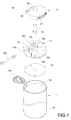
FIG. 1 is a perspective exploded view of a rechargeable battery according to the first embodiment of the present invention, -
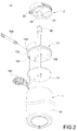
FIG. 2 is another perspective exploded view of the rechargeable battery according to the first embodiment of the present invention, -
FIG. 3 is a perspective assembled view showing the rechargeable battery according to the first embodiment of the present invention, -
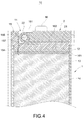
FIG. 4 is a cross-sectional view showing the rechargeable battery according to the first embodiment of the present invention, -
FIG. 5 is another cross-sectional view showing the rechargeable battery according to the first embodiment of the present invention, -
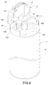
FIG. 6 is a schematic view showing the rechargeable battery in use according to the first embodiment of the present invention, -
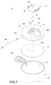
FIG. 7 is a perspective exploded view showing the rechargeable battery according to the second embodiment of the present invention, -
FIG. 8 is a perspective assembled view showing the rechargeable battery according to the second embodiment of the present invention, -
FIG. 9 is a perspective exploded view showing the rechargeable battery according to the third embodiment of the present invention, -
FIG. 10 is a perspective assembled view showing the rechargeable battery according to the third embodiment of the present invention, -
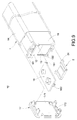
FIG. 11 is a perspective exploded view showing the rechargeable battery according to the fourth embodiment of the present invention, and -
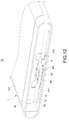
FIG. 12 is a perspective assembled view showing the rechargeable battery according to the fourth embodiment of the present invention. - Please refer to
Figs. 1 to 8 showing arechargeable battery 10 according to the first and second embodiments of the present invention. The rechargeable battery includes abattery body 1 and aconnector plug 2. - Referring to
Figs. 1 to 6 , thebattery body 1 includes arecess 11, acircuit board 12 and acell 13 are disposed inside thebattery body 1, and thecircuit board 12 is electrically connected to thecell 13. - In detail, the
battery body 1 includes asleeve 14 and acover 15, thecircuit board 12 and thecell 13 are accommodated in thesleeve 14, thecover 15 is fitted on thesleeve 14 and covers thecircuit board 12 and thecell 13, and therecess 11 is openly disposed on thecover 15. Thecover 15 includes aninner wall 151 and abottom 152 corresponding to therecess 11, theinner wall 151 includes afirst pivot hole 153, thebottom 152 includes a plurality of throughholes 154 and avent 155. - The
cover 15 includes apivot shaft 156 and a plurality ofconductive plates 157. Each of theconductive plates 157 is fixedly inserted through each of the throughholes 154 and electrically connected to thecircuit board 12. - Referring to
Figs. 1 to 6 , theconnector plug 2 is pivotally connected to thebattery body 1 and electrically connected to thecircuit board 12. Theconnector plug 2 is foldable to be received in therecess 11. Theconnector plug 2 can be a universal serial bus (USB) plug or a high-definition multimedia interface (HDMI) plug. - To be specific, the
connector plug 2 includes a plurality ofconductive terminals 21, asecond pivot hole 22, and anopening 23. Thepivot shaft 156 is pivotally connected to thefirst pivot hole 153 and thesecond pivot hole 22. An end of each of theconductive plates 157 is disposed corresponding to each of theconductive terminals 21 and electrically connectable to each of theconductive terminals 21. - Referring to
Figs. 1 to 6 , thebattery body 1 further includes anelectrode cap 16. Theelectrode cap 16 is fixedly inserted through thevent 155 and electrically connected to thecircuit board 12. When theconnector plug 2 is folded to be received in therecess 11, theelectrode cap 16 is inserted through and protrudes from theopening 23. - Referring to
Figs. 4 and5 , thebattery body 1 further includes asealant 161; thesealant 161 is filled between thecircuit board 12 and thecell 13, and thesealant 161 and thesleeve 14 together seal thecell 13. - Furthermore,
Figs. 1 to 6 show therechargeable battery 10 according to the first embodiment of the present invention, andFigs. 7 and8 show the rechargeable battery according to the second embodiment of the present invention. The second embodiment is similar to the first embodiment. The difference between the first embodiment and the second embodiment is that thebattery body 1 of the first embodiment is an AAA battery, and thebattery body 1 of the second embodiment is an AA battery. Therefore, therechargeable body 1 can be a D, C, AA, AAA, 9 volt, or a Nickel-Metal-Hydride battery; the present invention is not limited to the aforesaid embodiments. - Referring to
Figs. 1 to 3 , in therechargeable battery 10 of the present invention, thebattery body 1 includes therecess 11, thecircuit board 12 and thecell 13 are disposed inside thebattery body 1, thecircuit board 12 is electrically connected to thecell 13; theconnector plug 2 is pivotally connected to thebattery body 1 and electrically connected to thecircuit board 12, theconnector plug 2 is foldable to be received in therecess 11. Accordingly, theconnector plug 2 is pivotally connected to thebattery body 1 and is foldable to be received in therecess 11, so thebattery body 1 can be charged by means of theconnector plug 2 connected to an external power supply, thereby improving convenience in using therechargeable battery 10. - Please refer to
Figs. 4 to 6 showing therechargeable battery 10 in use. Theconnector plug 2 is pivotally connected to thebattery body 1 and is foldable to be received in therecess 11. As shown inFig. 4 , when theconnector plug 2 is folded and received in therecess 11, therechargeable battery 10 looks like an ordinary rechargeable battery, and therechargeable battery 10 can charge a portable electronic device. As shown inFigs. 5 and6 , when the connector plug 2 protrudes from therecess 11, theconnector plug 2 is electrically connected tocircuit board 12 via theconductive plate 157, so thebattery body 1 can be recharged by means of theconnector plug 2 connected to the external power supply, thereby improving convenience in using therechargeable battery 10. - Please refer to
Figs. 9 and10 showing the third embodiment of therechargeable battery 10 of the present invention. The third embodiment is similar to the first embodiment. The difference between the third embodiment and the first embodiment is that theconnector plug 2 has a different pivot structure for connecting thebattery body 1. - To be specific, the
battery body 1 includes asleeve 14, a coveringmember 17, anelectrode plate 18, and acell frame 19. Thecell 13 is inserted through thecell frame 19 and positioned by thecell frame 19, thecircuit board 12, thecell 13, and thecell frame 19 are accommodated in thesleeve 14, the coveringmember 17 and thecell frame 19 are assembled to each other to cover thecircuit board 12 and thecell 13, thecovering member 17 includes anopen hole 171, theelectrode plate 18 and theconnector plug 2 are pivotally connected between the coveringmember 17 and thecell frame 19, and therecess 11 is formed between theopen hole 171 and thecell 13. - Furthermore, two first
curved blocks 191 extend from one side of at least one of the coveringmember 17 and thecell frame 19, two secondcurved blocks 192 extend from the other side, afirst shaft 181 extends from theelectrode plate 18, asecond shaft 24 extends from theconnector plug 2, thefirst shaft 181 is pivotally connected to the firstcurved block 191, and thesecond shaft 24 is pivotally connected to the secondcurved block 192, so that theelectrode plate 18 is pivotally connected to one side of the coveringmember 17 and thecell frame 19, and theconnector plug 2 is pivotally connected to the other side of the coveringmember 17 and thecell frame 19. Theconnector plug 2 and thecircuit board 12 are disposed between theelectrode plate 18 and thecell 13 and are adjacent and juxtaposed to each other. - Moreover, the covering
member 17 includes anengagement groove 172 close to a surface of thecell 13, afastener 182 extends from one end of theelectrode plate 18 away from thefirst shaft 181 in a direction toward thecell 13, and thefastener 182 is engageable with theengagement groove 172. - Accordingly, as shown in
Fig. 10 , thefastener 182 is detached from theengagement groove 172, theelectrode plate 18 is opened from theopen hole 171 to expose theconnector plug 2 and allow theconnector plug 2 to be moved outwardly to protrude from therecess 11, so that thebattery body 1 can be charged by means of theconnector plug 2 connected to the external power supply, thus improving convenience in using therechargeable battery 10. - Furthermore, the
rechargeable body 1 can be a D, C, AA, AAA, 9 volt, or a Nickel-Metal-Hydride battery; the present invention is not limited to the present embodiment. - Please refer to
Figs. 11 and12 showing the fourth embodiment of therechargeable battery 10 of the present invention. The fourth embodiment is similar to the first embodiment. The difference between the fourth embodiment and the first embodiment is that theconnector plug 2 has a different pivot structure for connecting thebattery body 1. - To be specific, the
battery body 1 includes abattery cover 141, a coveringmember 17 and acell frame 19, thecell 13 is inserted in thecell frame 19 and positioned by thecell frame 19, thebattery cover 141 covers corresponding to an upper side of thecell frame 19, thecircuit board 12 and thecell 13 are disposed between thebattery cover 141 and thecell frame 19, the coveringmember 17 and thecell frame 19 are assembled to each other and cover thecircuit board 12 and thecell 13, the coveringmember 17 includes anopen hole 171 and anextension board 173 extending from theopen hole 171 toward thecell 13, theconnector plug 2 is pivotally connected to theextension board 173, and therecess 11 is formed between theopen hole 171 and thecell 13. - Moreover, the
connector plug 2 includes a lefthalf connector plug 25 and a righthalf connector plug 26 connected to or detached from each other, apivot rod 251 extends from the lefthalf connector plug 25, the righthalf connector plug 26 includes acircular sleeve 261, theextension board 173 includes apivot hole 174, and thepivot rod 251 is pivotally connected to thecircular sleeve 261 and thepivot hole 174, so that the lefthalf connector plug 25 and the righthalf connector plug 26 are pivotally connected to theextension board 173. - Therefore, as shown in
Fig. 12 , the lefthalf connector plug 25 and the righthalf connector plug 26 can be moved outward via theopen hole 171, so that the lefthalf connector plug 25 and the righthalf connector plug 26 are connected to form theconnector plug 2, and theconnector plug 2 protrudes out of therecess 11, and thereby thebattery body 1 can be charged by means of theconnector plug 2 connected to the external power supply, and it is convenient to use therechargeable battery 10. - In summary, the rechargeable battery of the present invention is neither disclosed by similar products nor used in public, has industrial applicability, novelty and non-obviousness, so the present invention completely complies with the requirements of patentability. Therefore, a request to patent the present invention is filed pursuant to patent law. Examination is kindly requested, and allowance of the present application is solicited to protect the rights of the inventor.
Claims (12)
- A rechargeable battery (10), characterized by:a battery body (1), the battery body (1) comprising a recess (11), a circuit board (12) and a cell (13) being disposed inside the battery body (1), the circuit board (12) being electrically connected to the cell (13); anda connector plug (2) pivotally connected to the battery body (1) and electrically connected to the circuit board (12), the connector plug (2) being foldable to be received in the recess (11).
- The rechargeable battery (10) of claim 1, further characterized in that the battery body (1) comprises a sleeve (14) and a cover (15), the circuit board (12) and the cell (13) are accommodated in the sleeve (14), the cover (15) is fitted on the sleeve (14) and covers the circuit board (12) and the cell (13), and the recess (11) is openly disposed on the cover (15).
- The rechargeable battery (10) of claim 2, further characterized in that the cover (15) comprises an inner wall (151) and a bottom (152) corresponding to the recess (11), the inner wall (151) comprises a first pivot hole (153), the bottom (152) comprises a plurality of through holes (154), the connector plug (2) comprises a plurality of conductive terminals (21) and a second pivot hole (22), the cover (15) comprises a pivot shaft (156) and a plurality of conductive plates (157), the pivot shaft (156) is pivotally connected to the first pivot hole (153) and the second pivot hole (22), each of the conductive plates (157) is fixedly inserted through each of the through holes (154) and electrically connected to the circuit board (12), an end of each of the conductive plates (157) is disposed corresponding to each of the conductive terminals (21) and electrically connectable to each of the conductive terminals (21).
- The rechargeable battery (10) of claim 2, further characterized in that the battery body (1) further comprises an electrode cap (16), the cover (15) comprises a bottom (152) corresponding to the recess (11), the bottom (152) comprises a vent (155), the electrode cap (16) is fixedly inserted through the vent (155) and electrically connected to the circuit board (12), and the connector plug (2) comprises an opening (23) which the electrode cap (16) is inserted through and protrudes from.
- The rechargeable battery (10) of claim 2, further characterized in that the battery body (1) further comprises a sealant (161), the sealant (161) is filled between the circuit board (12) and the cell (13), and the sealant (161) and the sleeve (14) together seal the cell (13).
- The rechargeable battery (10) of claim 1, further characterized in that the battery body (1) comprises a sleeve (14), a covering member (17), an electrode plate (18), and a cell frame (19), the cell (13) is inserted through the cell frame (19) and positioned by the cell frame (19), the circuit board (12), the cell (13), and the cell frame (19) are accommodated in the sleeve (14), the covering member (17) and the cell frame (19) are assembled to each other to cover the circuit board (12) and the cell (13), the covering member (17) comprises an open hole (171), the electrode plate (18) and the connector plug (2) are pivotally connected between the covering member (17) and the cell frame (19), and the recess (11) is formed between the open hole (171) and the cell (13).
- The rechargeable battery (10) of claim 6, further characterized in that two first curved blocks (191) extend from one side of at least one of the covering member (17) and the cell frame (19), two second curved blocks (192) extend from the other side, a first shaft (181) extends from the electrode plate (18), a second shaft (24) extends from the connector plug (2), the first shaft (181) is pivotally connected to the first curved block (191), and the second shaft (24) is pivotally connected to the second curved block (192).
- The rechargeable battery (10) of claim 7, further characterized in that the covering member (17) comprises an engagement groove (172) close to a surface of the cell (13), a fastener (182) extends from one end of the electrode plate (18) away from the first shaft (181) in a direction toward the cell (13), and the fastener (182) is engageable with the engagement groove (172).
- The rechargeable battery (10) of claim 6, further characterized in that the connector plug (2) and the circuit board (12) are disposed between the electrode plate (18) and the cell (13) and are disposed adjacent and juxtaposed to each other.
- The rechargeable battery (10) of claim 1, further characterized in that the battery body (1) comprises a battery cover (141), a covering member (17) and a cell frame (19), the cell (13) is inserted in the cell frame (19) and positioned by the cell frame (19), the battery cover (141) covers corresponding to an upper side of the cell frame (19), the circuit board (12) and the cell (13) are disposed between the battery cover (141) and the cell frame (19), the covering member (17) and the cell frame (19) are assembled to each other and cover the circuit board (12) and the cell (13), the covering member (17) comprises an open hole (171) and an extension board (173) extending from the open hole (171) toward the cell (13), the connector plug (2) is pivotally connected to the extension board (173), and the recess (11) is formed between the open hole (171) and the cell (13).
- The rechargeable battery (10) of claim 10, further characterized in that the connector plug (2) comprises a left half connector plug (25) and a right half connector plug (26) connected to or detached from each other, a pivot rod (251) extends from the left half connector plug (25), the right half connector plug (26) comprises a circular sleeve (261), the extension board (173) comprises a pivot hole (174), and the pivot rod (251) is pivotally connected to the circular sleeve (261) and the pivot hole (174).
- The rechargeable battery (10) of claim 1, further characterized in that the connector plug (2) is a universal serial bus (USB) plug or a high-definition multimedia interface (HDMI) plug.
Applications Claiming Priority (1)
| Application Number | Priority Date | Filing Date | Title |
|---|---|---|---|
| TW104115161A TWI601329B (en) | 2015-05-13 | 2015-05-13 | Rechargeable battery |
Publications (2)
| Publication Number | Publication Date |
|---|---|
| EP3093900A2 true EP3093900A2 (en) | 2016-11-16 |
| EP3093900A3 EP3093900A3 (en) | 2016-12-28 |
Family
ID=55963234
Family Applications (1)
| Application Number | Title | Priority Date | Filing Date |
|---|---|---|---|
| EP16169078.9A Withdrawn EP3093900A3 (en) | 2015-05-13 | 2016-05-11 | Rechargeable battery |
Country Status (5)
| Country | Link |
|---|---|
| US (1) | US10276839B2 (en) |
| EP (1) | EP3093900A3 (en) |
| JP (1) | JP2016213193A (en) |
| KR (1) | KR20160134522A (en) |
| TW (1) | TWI601329B (en) |
Families Citing this family (9)
| Publication number | Priority date | Publication date | Assignee | Title |
|---|---|---|---|---|
| US12009486B2 (en) * | 2017-11-06 | 2024-06-11 | Eve Energy Co., Ltd. | Safe and high-energy USB rechargeable battery |
| CN110611130A (en) * | 2018-06-15 | 2019-12-24 | 元创绿能科技股份有限公司 | Rechargeable battery and method for controlling electron dissociation of metal atoms for charging |
| CN109560318B (en) * | 2018-12-29 | 2024-01-26 | 桂林市啄木鸟医疗器械有限公司 | Rechargeable battery and hot-melt gutta-percha pen |
| CN110931699B (en) * | 2019-11-14 | 2022-01-04 | 深圳先进储能材料国家工程研究中心有限公司 | Double-end input chargeable secondary battery |
| CN111063856B (en) * | 2019-12-17 | 2022-06-10 | 深圳先进储能材料国家工程研究中心有限公司 | Secondary batteries based on needle-shaped lead cells |
| CN111934150A (en) * | 2020-08-05 | 2020-11-13 | 苏州车萝卜汽车电子科技有限公司 | Rotatable circuit connection fixed knot constructs |
| US20240274949A1 (en) * | 2021-07-19 | 2024-08-15 | Lg Energy Solution, Ltd. | Cell assembly |
| USD1079601S1 (en) * | 2022-07-18 | 2025-06-17 | Xiamen Hithium Energy Storage Technology Co., Ltd. | Cylindrical battery |
| USD1079600S1 (en) * | 2022-08-29 | 2025-06-17 | Xiamen Hithium Energy Storage Technology Co., Ltd. | Cylindrical battery |
Family Cites Families (8)
| Publication number | Priority date | Publication date | Assignee | Title |
|---|---|---|---|---|
| US5057381A (en) * | 1990-12-20 | 1991-10-15 | David Persen | Satellite rechargeable battery and recharger system |
| KR20010000803U (en) | 1999-06-18 | 2001-01-15 | 석찬복 | A rechargeable battery |
| WO2006056744A1 (en) | 2004-11-25 | 2006-06-01 | Moixa Energy Holdings Limited | Rechargeable battery assembly |
| TWM286495U (en) * | 2005-07-08 | 2006-01-21 | Hon Hai Prec Ind Co Ltd | Electrical connector assembly |
| US8058840B2 (en) | 2006-05-25 | 2011-11-15 | Moxia Energy Holdings Limited | Rechargeable battery assembly with movable connector and power conversion circuitry |
| KR200442869Y1 (en) | 2007-01-30 | 2008-12-17 | 한대승 | Multifunction lithium ion charger |
| KR101006881B1 (en) * | 2007-12-14 | 2011-01-12 | 주식회사 엘지화학 | Improved fastening structure PCM and battery pack containing the same |
| CA2781691A1 (en) * | 2009-10-29 | 2011-05-05 | Anthony Peacock | Electronic device back-up charger |
-
2015
- 2015-05-13 TW TW104115161A patent/TWI601329B/en not_active IP Right Cessation
-
2016
- 2016-04-21 US US15/134,385 patent/US10276839B2/en not_active Expired - Fee Related
- 2016-05-10 JP JP2016105652A patent/JP2016213193A/en active Pending
- 2016-05-11 EP EP16169078.9A patent/EP3093900A3/en not_active Withdrawn
- 2016-05-11 KR KR1020160057675A patent/KR20160134522A/en not_active Ceased
Non-Patent Citations (1)
| Title |
|---|
| None |
Also Published As
| Publication number | Publication date |
|---|---|
| JP2016213193A (en) | 2016-12-15 |
| US10276839B2 (en) | 2019-04-30 |
| TWI601329B (en) | 2017-10-01 |
| TW201640716A (en) | 2016-11-16 |
| EP3093900A3 (en) | 2016-12-28 |
| US20160336551A1 (en) | 2016-11-17 |
| KR20160134522A (en) | 2016-11-23 |
Similar Documents
| Publication | Publication Date | Title |
|---|---|---|
| US10276839B2 (en) | Rechargeable battery | |
| KR101472537B1 (en) | Rechargeable battery with Universal Serial Bus connecter | |
| US10033294B2 (en) | Folding plug with safety cover | |
| US9337920B2 (en) | Cabinet with power supply arrangement | |
| US20150207350A1 (en) | Power charging socket | |
| CN108352474A (en) | Battery pack, electrical equipment and charging equipment | |
| KR20130097954A (en) | Case for mobile | |
| CN102437490A (en) | Micro universal serial bus adapter | |
| US20180083464A1 (en) | Charging case for an electronic device | |
| US20160149425A1 (en) | Charging connector of mobile power pack | |
| US20130221922A1 (en) | Universal serial bus charging device | |
| US20180090964A1 (en) | Apparatus for powering an electrical device from different battery packs | |
| KR101456701B1 (en) | The case for charging a bettery | |
| CN201611678U (en) | Multifunctional charger | |
| KR101505664B1 (en) | Rechargeable battery with universal serial bus connecter | |
| CN208423885U (en) | Multi-functional multioutlet quick charger | |
| CN203268672U (en) | Electronic product protective sleeve | |
| US20140292255A1 (en) | Usb charging structure of mobile power pack | |
| CN205610250U (en) | On -vehicle charger with rotatory lid | |
| CN206378890U (en) | A kind of Multifunctional U disk and mobile storage | |
| CN105429205A (en) | Charging apparatus with pivoting structure | |
| US20100167796A1 (en) | Electronic device | |
| CN204179709U (en) | Charging connection for mobile power | |
| CN203387220U (en) | Wireless charging device | |
| CN208112262U (en) | Portable movable charger shell structure and Portable movable charger |
Legal Events
| Date | Code | Title | Description |
|---|---|---|---|
| PUAI | Public reference made under article 153(3) epc to a published international application that has entered the european phase |
Free format text: ORIGINAL CODE: 0009012 |
|
| AK | Designated contracting states |
Kind code of ref document: A2 Designated state(s): AL AT BE BG CH CY CZ DE DK EE ES FI FR GB GR HR HU IE IS IT LI LT LU LV MC MK MT NL NO PL PT RO RS SE SI SK SM TR |
|
| AX | Request for extension of the european patent |
Extension state: BA ME |
|
| PUAL | Search report despatched |
Free format text: ORIGINAL CODE: 0009013 |
|
| AK | Designated contracting states |
Kind code of ref document: A3 Designated state(s): AL AT BE BG CH CY CZ DE DK EE ES FI FR GB GR HR HU IE IS IT LI LT LU LV MC MK MT NL NO PL PT RO RS SE SI SK SM TR |
|
| AX | Request for extension of the european patent |
Extension state: BA ME |
|
| RIC1 | Information provided on ipc code assigned before grant |
Ipc: H01M 2/20 20060101ALI20161118BHEP Ipc: H01R 13/02 20060101ALI20161118BHEP Ipc: H01M 2/04 20060101AFI20161118BHEP Ipc: H01R 9/00 20060101ALI20161118BHEP Ipc: H01M 10/42 20060101ALI20161118BHEP |
|
| STAA | Information on the status of an ep patent application or granted ep patent |
Free format text: STATUS: REQUEST FOR EXAMINATION WAS MADE |
|
| 17P | Request for examination filed |
Effective date: 20170626 |
|
| RBV | Designated contracting states (corrected) |
Designated state(s): AL AT BE BG CH CY CZ DE DK EE ES FI FR GB GR HR HU IE IS IT LI LT LU LV MC MK MT NL NO PL PT RO RS SE SI SK SM TR |
|
| STAA | Information on the status of an ep patent application or granted ep patent |
Free format text: STATUS: EXAMINATION IS IN PROGRESS |
|
| 17Q | First examination report despatched |
Effective date: 20180831 |
|
| RIC1 | Information provided on ipc code assigned before grant |
Ipc: H01R 13/02 20060101ALI20190621BHEP Ipc: H01R 9/00 20060101ALI20190621BHEP Ipc: H01M 2/10 20060101ALI20190621BHEP Ipc: H01R 35/04 20060101ALI20190621BHEP Ipc: H01M 2/20 20060101ALI20190621BHEP Ipc: H01M 10/42 20060101ALI20190621BHEP Ipc: H01M 2/06 20060101ALI20190621BHEP Ipc: H01M 10/46 20060101ALI20190621BHEP Ipc: H01M 2/04 20060101AFI20190621BHEP |
|
| GRAP | Despatch of communication of intention to grant a patent |
Free format text: ORIGINAL CODE: EPIDOSNIGR1 |
|
| STAA | Information on the status of an ep patent application or granted ep patent |
Free format text: STATUS: GRANT OF PATENT IS INTENDED |
|
| INTG | Intention to grant announced |
Effective date: 20191122 |
|
| STAA | Information on the status of an ep patent application or granted ep patent |
Free format text: STATUS: THE APPLICATION IS DEEMED TO BE WITHDRAWN |
|
| 18D | Application deemed to be withdrawn |
Effective date: 20191203 |