EP3093890A1 - Photovoltaic module and interlocked stack of photovoltaic modules - Google Patents
Photovoltaic module and interlocked stack of photovoltaic modules Download PDFInfo
- Publication number
- EP3093890A1 EP3093890A1 EP16177994.7A EP16177994A EP3093890A1 EP 3093890 A1 EP3093890 A1 EP 3093890A1 EP 16177994 A EP16177994 A EP 16177994A EP 3093890 A1 EP3093890 A1 EP 3093890A1
- Authority
- EP
- European Patent Office
- Prior art keywords
- alignment features
- top member
- frame
- male
- photovoltaic modules
- Prior art date
- Legal status (The legal status is an assumption and is not a legal conclusion. Google has not performed a legal analysis and makes no representation as to the accuracy of the status listed.)
- Granted
Links
Images




Classifications
-
- F—MECHANICAL ENGINEERING; LIGHTING; HEATING; WEAPONS; BLASTING
- F24—HEATING; RANGES; VENTILATING
- F24S—SOLAR HEAT COLLECTORS; SOLAR HEAT SYSTEMS
- F24S25/00—Arrangement of stationary mountings or supports for solar heat collector modules
- F24S25/20—Peripheral frames for modules
-
- H—ELECTRICITY
- H02—GENERATION; CONVERSION OR DISTRIBUTION OF ELECTRIC POWER
- H02S—GENERATION OF ELECTRIC POWER BY CONVERSION OF INFRARED RADIATION, VISIBLE LIGHT OR ULTRAVIOLET LIGHT, e.g. USING PHOTOVOLTAIC [PV] MODULES
- H02S30/00—Structural details of PV modules other than those related to light conversion
- H02S30/10—Frame structures
-
- H—ELECTRICITY
- H01—ELECTRIC ELEMENTS
- H01R—ELECTRICALLY-CONDUCTIVE CONNECTIONS; STRUCTURAL ASSOCIATIONS OF A PLURALITY OF MUTUALLY-INSULATED ELECTRICAL CONNECTING ELEMENTS; COUPLING DEVICES; CURRENT COLLECTORS
- H01R12/00—Structural associations of a plurality of mutually-insulated electrical connecting elements, specially adapted for printed circuits, e.g. printed circuit boards [PCB], flat or ribbon cables, or like generally planar structures, e.g. terminal strips, terminal blocks; Coupling devices specially adapted for printed circuits, flat or ribbon cables, or like generally planar structures; Terminals specially adapted for contact with, or insertion into, printed circuits, flat or ribbon cables, or like generally planar structures
-
- H—ELECTRICITY
- H02—GENERATION; CONVERSION OR DISTRIBUTION OF ELECTRIC POWER
- H02S—GENERATION OF ELECTRIC POWER BY CONVERSION OF INFRARED RADIATION, VISIBLE LIGHT OR ULTRAVIOLET LIGHT, e.g. USING PHOTOVOLTAIC [PV] MODULES
- H02S20/00—Supporting structures for PV modules
- H02S20/20—Supporting structures directly fixed to an immovable object
- H02S20/22—Supporting structures directly fixed to an immovable object specially adapted for buildings
- H02S20/23—Supporting structures directly fixed to an immovable object specially adapted for buildings specially adapted for roof structures
-
- H—ELECTRICITY
- H10—SEMICONDUCTOR DEVICES; ELECTRIC SOLID-STATE DEVICES NOT OTHERWISE PROVIDED FOR
- H10F—INORGANIC SEMICONDUCTOR DEVICES SENSITIVE TO INFRARED RADIATION, LIGHT, ELECTROMAGNETIC RADIATION OF SHORTER WAVELENGTH OR CORPUSCULAR RADIATION
- H10F77/00—Constructional details of devices covered by this subclass
-
- F—MECHANICAL ENGINEERING; LIGHTING; HEATING; WEAPONS; BLASTING
- F24—HEATING; RANGES; VENTILATING
- F24S—SOLAR HEAT COLLECTORS; SOLAR HEAT SYSTEMS
- F24S25/00—Arrangement of stationary mountings or supports for solar heat collector modules
- F24S2025/01—Special support components; Methods of use
- F24S2025/013—Stackable support elements
-
- Y—GENERAL TAGGING OF NEW TECHNOLOGICAL DEVELOPMENTS; GENERAL TAGGING OF CROSS-SECTIONAL TECHNOLOGIES SPANNING OVER SEVERAL SECTIONS OF THE IPC; TECHNICAL SUBJECTS COVERED BY FORMER USPC CROSS-REFERENCE ART COLLECTIONS [XRACs] AND DIGESTS
- Y02—TECHNOLOGIES OR APPLICATIONS FOR MITIGATION OR ADAPTATION AGAINST CLIMATE CHANGE
- Y02B—CLIMATE CHANGE MITIGATION TECHNOLOGIES RELATED TO BUILDINGS, e.g. HOUSING, HOUSE APPLIANCES OR RELATED END-USER APPLICATIONS
- Y02B10/00—Integration of renewable energy sources in buildings
- Y02B10/10—Photovoltaic [PV]
-
- Y—GENERAL TAGGING OF NEW TECHNOLOGICAL DEVELOPMENTS; GENERAL TAGGING OF CROSS-SECTIONAL TECHNOLOGIES SPANNING OVER SEVERAL SECTIONS OF THE IPC; TECHNICAL SUBJECTS COVERED BY FORMER USPC CROSS-REFERENCE ART COLLECTIONS [XRACs] AND DIGESTS
- Y02—TECHNOLOGIES OR APPLICATIONS FOR MITIGATION OR ADAPTATION AGAINST CLIMATE CHANGE
- Y02E—REDUCTION OF GREENHOUSE GAS [GHG] EMISSIONS, RELATED TO ENERGY GENERATION, TRANSMISSION OR DISTRIBUTION
- Y02E10/00—Energy generation through renewable energy sources
- Y02E10/40—Solar thermal energy, e.g. solar towers
- Y02E10/47—Mountings or tracking
-
- Y—GENERAL TAGGING OF NEW TECHNOLOGICAL DEVELOPMENTS; GENERAL TAGGING OF CROSS-SECTIONAL TECHNOLOGIES SPANNING OVER SEVERAL SECTIONS OF THE IPC; TECHNICAL SUBJECTS COVERED BY FORMER USPC CROSS-REFERENCE ART COLLECTIONS [XRACs] AND DIGESTS
- Y02—TECHNOLOGIES OR APPLICATIONS FOR MITIGATION OR ADAPTATION AGAINST CLIMATE CHANGE
- Y02E—REDUCTION OF GREENHOUSE GAS [GHG] EMISSIONS, RELATED TO ENERGY GENERATION, TRANSMISSION OR DISTRIBUTION
- Y02E10/00—Energy generation through renewable energy sources
- Y02E10/50—Photovoltaic [PV] energy
Definitions
- the present disclosure relates to photovoltaic modules and the transportation and installation thereof.
- Photovoltaic cells also known as “solar cells,” are devices for converting solar radiation to electrical energy. Photovoltaic cells are typically arranged into an array and packaged as a photovoltaic (PV) module, also known as a “solar module.”
- PV photovoltaic
- Photovoltaic modules may also be installed in solar collector arrays with capacities from a few kilowatts to hundreds of kilowatts, or more. These arrays are typically installed where there is a reasonably flat area with exposure to the sun for significant portions of the day.
- a substantial portion of the cost associated with solar collector arrays relates to the transportation and installation of the photovoltaic modules. Hence, it is highly desirable to improve methods and apparatus of transporting and installing photovoltaic modules.
- One embodiment relates to an arrangement of photovoltaic modules configured for transportation.
- the arrangement includes a plurality of photovoltaic modules, each photovoltaic module including a frame having at least a top member and a bottom member.
- a plurality of alignment features are included on the top member of each frame, and a plurality of alignment features are included on the bottom member of each frame.
- Adjacent photovoltaic modules are interlocked by the alignment features on the top member of a lower module fitting together with the alignment features on the bottom member of an upper module.
- the module includes an array of solar cells and a frame for supporting the array of solar cells.
- the frame includes a top member and a bottom member connected by a side member.
- a plurality of alignment features are included on the top member, and a plurality of alignment features are included on the bottom member.
- the alignment features on the bottom member are configured to couple with the alignment features on the top member of another module.
- FIG. 1 depicts a first example solar collector arrangement 10.
- a single row 11 is shown, but the array can comprise several rows 11 joined end to end, and can comprise any number of such rows side by side.
- a row of solar panels 14 i.e., photovoltaic modules, is attached onto a torsion tube 12 .
- the row has sixty panels or modules 14 , i.e., thirty sets of two modules.
- There are four vertical pier tubes 16 which can be round or square cross section, as desired, each supported in the earth.
- each pier tube 16 may be a pier cap weldment 20, which may have a transverse square tubular sleeve that fits the profile of the torsion tube 12 .
- the pier caps 20 on the pier tubes 16 may be aligned so that the torsion tube 12 threads through them.
- FIG. 2 depicts a second example solar collector arrangement 50 with an array of photovoltaic modules 52 supported by a roof. As shown, the modules 52 may be installed flush or relatively close to a roof plane 54.
- Photovoltaic modules are typically packed and shipped in cardboard boxes. As depicted in FIG. 3 , multiple boxes 302 are generally stacked on top of each other and shipped together as a unit. The stack of boxes 302 are typically strapped to a wood pallet 304 and shipped together as a unit. Two solar modules may be included in each cardboard box with a cardboard sheet between them.
- FIG. 4 Another packaging solution for solar modules is depicted in FIG. 4 .
- This solution uses corner elements 402 to support and stack multiple modules 404 on top of each other. The stack with the corner elements is then strapped to a wood pallet 406 and shipped together as a unit.
- the conventional solution of packaging the modules in cardboard boxes results in extra cost for the boxes.
- the cardboard material takes up space in a stack of modules being shipped and so reduces the shipping density of the modules.
- a lower shipping density means that fewer modules may be shipped in a fixed volumetric size of a shipping container.
- the packaging solution which uses corner elements results in substantial space between modules, both horizontally and vertically, in a shipping stack. Hence, this solution also results in a relatively low shipping density. Furthermore, there is also the cost of the corner elements, the need to dispose of or recycle the corner elements at the installation site, and in some cases return shipping of the corners to the manufacturer.
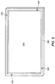
- FIG. 5 depicts (in perspective view from the top) a frame for a photovoltaic module with a stacking feature in accordance with an embodiment of the invention. Exemplary profiles for the frame are described below in relation to FIGS. 6 and 7 .
- the module frame 502 may be a rectangular frame which is configured to frame and support a photovoltaic module. (The module is configured in the framed area 504 .)
- the module frame includes (male) alignment features 506 which protrude from the top surface of the frame.
- these alignment features 506 enable an advantageous packaging solution for the transportation of the photovoltaic modules.
- an alignment feature 506 may be included on each side of the top surface of the frame and positioned relatively close to a corner of the frame. Other implementations may position the alignment features 506 at different locations on the top surface of the frame.
- FIG. 6 shows a first profile of a module frame with an alignment feature in accordance with an embodiment of the invention.
- the frame includes a side member 602 which attaches to and separates a top member 608 and a bottom member 604 .
- a slot 606 towards the top of the frame is configured to hold and support the photovoltaic cells within the frame. (The top faces the sunlight after installation of the module.)
- the photovoltaic cells form a silicon layer 624 which may be sandwiched between a glass layer 622 and a polymer layer 626 .
- male alignment features for example, pins or raised track
- the alignment features 506 may be inserted into the top surface of the frame during the frame manufacturing process.
- the inserted alignment features 506 preferably remain above and do not break the glass layer 622 so as to maintain the integrity of the enclosure for the silicon cells.
- the alignment features 506 may be formed during the extrusion of the frame.
- Corresponding female alignment features (for example, holes or grooves) 610 are also formed in the bottom member of the frame. These female alignment features 610 are formed on the bottom area of the frame at locations which correspond to (and in case of pins and holes, coaxially align with) the locations of the male alignment features 506 on the top area of the frame. As such, with these male and female alignment features, the module frames may be directly stacked on each other in a secure and interlocked manner. In one embodiment, one or more of the corresponding holes may also function as drain holes at the bottom of the frame.
- FIG. 7 shows a second profile of a module frame with male and female alignment features in accordance with an embodiment of the invention.
- the frame includes a side member 702 which is coupled to a top member 708 and bottom members 704 and 705 .
- a slot 706 towards the top of the frame is configured to hold and support the photovoltaic cells within the frame.
- the photovoltaic cells form a silicon layer 724 which may be sandwiched between a glass layer 722 and a polymer layer 726 .
- channels 712 which may be used to provide an anchor for self-tapping screws.
- male alignment features 506 are included at selected positions to the top surface of the frame.
- the male alignment features (for example, pins or raised tracks) 506 may be inserted into the top surface of the frame during the frame manufacturing process.
- the inserted alignment features 506 preferably remain above and do not break the glass layer 722 so as to maintain the integrity of the enclosure for the silicon cells.
- the alignment features 506 may be formed during the extrusion of the frame.
- Corresponding female alignment features are also formed in the bottom member of the frame. These female alignment features 710 are formed on the bottom area of the frame at locations which correspond to (and in the case of pins and holes, coaxially align with) the locations of the male alignment features 506 on the top area of the frame. As such, with these male and female alignment features, the module frames may be directly stacked on each other in a secure and interlocked manner. In one embodiment, one or more of the corresponding holes may also function as drain holes at the bottom of the frame.
- FIG. 8 depicts an exemplary alignment feature 804 attached to a module frame 802 in accordance with an embodiment of the invention.
- this (male) alignment feature 804 may comprise a protruding portion 806 that rises above the top surface of the frame and an embedded portion 808 that secures it to the frame.
- the alignment feature 804 is implemented using a self-clinching fastener.
- the fastener may be installed in the top surface of the frame by drilling a hole at the location for the alignment feature and then inserting the self-clinching portion of the fastener into the drilled hole using an automated press.
- the embedded portion may be a screw which may be screwed into a screw hole formed in the frame.
- the alignment feature may be removed, if desired, after un-stacking the modules.
- Other means may also be used for attaching the alignment feature to the module frame.
- the protruding portion 806 is preferably tall enough to engage the adjacent frame that is stacked on top of it.
- the protruding portion is also short enough so that chance of breakage from a side force is low and so that the protruding feature does not interfere with movement of the solar module.
- the protruding portion is preferably sufficiently short so as to avoid undesirable shading of the photovoltaic module during operation.
- FIG. 9 depicts stack of photovoltaic modules 902 which are interlocked with each other in accordance with an embodiment of the invention.
- the photovoltaic modules 902 may be stacked directly on each other and held together, in part, using the male and female alignment features to interlock adjacent modules.
- the interlocked stack of modules 902 may be strapped to a wood pallet 904 and shipped together as a unit.
- Protective cardboard sheets may be used on the outside of the stack, but cardboard boxes are not used to hold the modules.
- Such an interlocked stack of solar modules is efficient because it provides for dense packing of the modules during transportation. This enables a greater number of modules to be shipped in a same volumetric space compared to prior packaging techniques. The wasted space taken by the cardboard boxes, or created by the corner elements, is avoided.
- FIG. 10 shows a profile of a module frame in an alternate embodiment of the invention.
- the frame includes a side member 1002 which attaches to and separates a top member 1008 and a bottom member 1004 .
- a slot 1006 towards the top of the frame is configured to hold and support the photovoltaic cells within the frame.
- the photovoltaic cells form a silicon layer 1024 which may be sandwiched between a glass layer 1022 and a polymer layer 1026 .
- a lip 1009 is included at the outer edge of the bottom of the frame.
- the lip 1009 is configured so as to form inner corners 1010 with the bottom surface of the frame.
- the inner corners 1010 fit onto and interlock with the outer corners 1012 at the top of the adjacent frame in the stack.
- the outer corners 1012 are formed by the side member 1002 and a top surface of the frame.
- an alternate embodiment may provide a female alignment feature on the top surface of a frame, and a corresponding male alignment feature on the bottom surface of the frame. Such features would also enable advantageous direct stacking of the photovoltaic modules for transportation.
Landscapes
- Engineering & Computer Science (AREA)
- Architecture (AREA)
- Structural Engineering (AREA)
- Civil Engineering (AREA)
- Sustainable Energy (AREA)
- Thermal Sciences (AREA)
- Chemical & Material Sciences (AREA)
- Combustion & Propulsion (AREA)
- Mechanical Engineering (AREA)
- General Engineering & Computer Science (AREA)
- Physics & Mathematics (AREA)
- Sustainable Development (AREA)
- Life Sciences & Earth Sciences (AREA)
- Packaging Frangible Articles (AREA)
- Photovoltaic Devices (AREA)
- Packaging Of Machine Parts And Wound Products (AREA)
- Pallets (AREA)
Abstract
Description
- The present disclosure relates to photovoltaic modules and the transportation and installation thereof.
- Photovoltaic cells, also known as "solar cells," are devices for converting solar radiation to electrical energy. Photovoltaic cells are typically arranged into an array and packaged as a photovoltaic (PV) module, also known as a "solar module."
- Photovoltaic modules may also be installed in solar collector arrays with capacities from a few kilowatts to hundreds of kilowatts, or more. These arrays are typically installed where there is a reasonably flat area with exposure to the sun for significant portions of the day.
- A substantial portion of the cost associated with solar collector arrays relates to the transportation and installation of the photovoltaic modules. Hence, it is highly desirable to improve methods and apparatus of transporting and installing photovoltaic modules.
- One embodiment relates to an arrangement of photovoltaic modules configured for transportation. The arrangement includes a plurality of photovoltaic modules, each photovoltaic module including a frame having at least a top member and a bottom member. A plurality of alignment features are included on the top member of each frame, and a plurality of alignment features are included on the bottom member of each frame. Adjacent photovoltaic modules are interlocked by the alignment features on the top member of a lower module fitting together with the alignment features on the bottom member of an upper module.
- Another embodiment relates to a photovoltaic module. The module includes an array of solar cells and a frame for supporting the array of solar cells. The frame includes a top member and a bottom member connected by a side member. A plurality of alignment features are included on the top member, and a plurality of alignment features are included on the bottom member. The alignment features on the bottom member are configured to couple with the alignment features on the top member of another module.
- Other embodiments, aspects and features are also disclosed.
-
-
FIG. 1 depicts a first example solar collector arrangement with an array of photovoltaic modules supported by a frame structure. -
FIG. 2 depicts a second example solar collector arrangement with an array of photovoltaic modules supported by a roof. -
FIG. 3 depicts a first conventional packaging solution for transporting photovoltaic modules. -
FIG. 4 depicts a second conventional packaging solution for transporting photovoltaic modules. -
FIG. 5 depicts a frame for a photovoltaic module with a stacking feature in accordance with an embodiment of the invention. -
FIG. 6 shows a first profile of a module frame with an alignment feature in accordance with an embodiment of the invention. -
FIG. 7 shows a second profile of a module frame with an alignment feature in accordance with an embodiment of the invention. -
FIG. 8 depicts an exemplary alignment feature attached to a module frame in accordance with an embodiment of the invention. -
FIG. 9 depicts stack of photovoltaic modules which are interlocked with each other in accordance with an embodiment of the invention. -
FIG. 10 shows a profile of a module frame in an alternate embodiment of the invention. - In the present disclosure, numerous specific details are provided, such as examples of apparatus, process parameters, materials, process steps, and structures, to provide a thorough understanding of embodiments of the invention. Persons of ordinary skill in the art will recognize, however, that the invention can be practiced without one or more of the specific details. In other instances, well-known details are not shown or described to avoid obscuring aspects of the invention.
-
FIG. 1 depicts a first examplesolar collector arrangement 10. In this view, asingle row 11 is shown, but the array can compriseseveral rows 11 joined end to end, and can comprise any number of such rows side by side. A row ofsolar panels 14, i.e., photovoltaic modules, is attached onto atorsion tube 12. - In this example arrangement, the row has sixty panels or
modules 14, i.e., thirty sets of two modules. There are fourvertical pier tubes 16, which can be round or square cross section, as desired, each supported in the earth. - At a top end of each
pier tube 16 may be apier cap weldment 20, which may have a transverse square tubular sleeve that fits the profile of thetorsion tube 12. Thepier caps 20 on thepier tubes 16 may be aligned so that thetorsion tube 12 threads through them. There may be multiple support rails orpanel rails 22 attached onto thetorsion tube 12, and theserails 22 may be arranged across tube at right angles to the tube axis and may be spaced apart the width of one panel ormodule 14. -
FIG. 2 depicts a second examplesolar collector arrangement 50 with an array ofphotovoltaic modules 52 supported by a roof. As shown, themodules 52 may be installed flush or relatively close to aroof plane 54. - Photovoltaic modules are typically packed and shipped in cardboard boxes. As depicted in
FIG. 3 ,multiple boxes 302 are generally stacked on top of each other and shipped together as a unit. The stack ofboxes 302 are typically strapped to a wood pallet 304 and shipped together as a unit. Two solar modules may be included in each cardboard box with a cardboard sheet between them. - Another packaging solution for solar modules is depicted in
FIG. 4 . This solution usescorner elements 402 to support and stackmultiple modules 404 on top of each other. The stack with the corner elements is then strapped to awood pallet 406 and shipped together as a unit. - Applicants have determined that these conventional packaging solutions have disadvantages and inefficiencies.
- The conventional solution of packaging the modules in cardboard boxes results in extra cost for the boxes. In addition, there is substantial work needed to unpack the modules and recycle the boxes at the installation site. For example, in a large installation, there is typically a worker dedicated to this task on unpacking and recycling boxes. Furthermore, the cardboard material takes up space in a stack of modules being shipped and so reduces the shipping density of the modules. A lower shipping density means that fewer modules may be shipped in a fixed volumetric size of a shipping container.
- The packaging solution which uses corner elements results in substantial space between modules, both horizontally and vertically, in a shipping stack. Hence, this solution also results in a relatively low shipping density. Furthermore, there is also the cost of the corner elements, the need to dispose of or recycle the corner elements at the installation site, and in some cases return shipping of the corners to the manufacturer.
-
FIG. 5 depicts (in perspective view from the top) a frame for a photovoltaic module with a stacking feature in accordance with an embodiment of the invention. Exemplary profiles for the frame are described below in relation toFIGS. 6 and7 . - As seen in
FIG. 5 , themodule frame 502 may be a rectangular frame which is configured to frame and support a photovoltaic module. (The module is configured in the framedarea 504.) In accordance with an embodiment of the present invention, the module frame includes (male) alignment features 506 which protrude from the top surface of the frame. In addition, there are corresponding holes (female alignment features) on the bottom surface of the frame. As discussed further below, these alignment features 506 enable an advantageous packaging solution for the transportation of the photovoltaic modules. - In one implementation, an
alignment feature 506 may be included on each side of the top surface of the frame and positioned relatively close to a corner of the frame. Other implementations may position the alignment features 506 at different locations on the top surface of the frame. -
FIG. 6 shows a first profile of a module frame with an alignment feature in accordance with an embodiment of the invention. As shown, the frame includes aside member 602 which attaches to and separates atop member 608 and abottom member 604. Aslot 606 towards the top of the frame is configured to hold and support the photovoltaic cells within the frame. (The top faces the sunlight after installation of the module.) The photovoltaic cells form a silicon layer 624 which may be sandwiched between aglass layer 622 and apolymer layer 626. - In accordance with an embodiment of the invention, male alignment features (for example, pins or raised track) 506 are included at selected positions to the top surface of the frame. The alignment features 506 may be inserted into the top surface of the frame during the frame manufacturing process. The inserted alignment features 506 preferably remain above and do not break the
glass layer 622 so as to maintain the integrity of the enclosure for the silicon cells. Alternatively, the alignment features 506 may be formed during the extrusion of the frame. - Corresponding female alignment features (for example, holes or grooves) 610 are also formed in the bottom member of the frame. These female alignment features 610 are formed on the bottom area of the frame at locations which correspond to (and in case of pins and holes, coaxially align with) the locations of the male alignment features 506 on the top area of the frame. As such, with these male and female alignment features, the module frames may be directly stacked on each other in a secure and interlocked manner. In one embodiment, one or more of the corresponding holes may also function as drain holes at the bottom of the frame.
-
FIG. 7 shows a second profile of a module frame with male and female alignment features in accordance with an embodiment of the invention. As shown, the frame includes aside member 702 which is coupled to atop member 708 andbottom members slot 706 towards the top of the frame is configured to hold and support the photovoltaic cells within the frame. The photovoltaic cells form asilicon layer 724 which may be sandwiched between aglass layer 722 and apolymer layer 726. Also shown arechannels 712 which may be used to provide an anchor for self-tapping screws. - In accordance with an embodiment of the invention, male alignment features 506 are included at selected positions to the top surface of the frame. The male alignment features (for example, pins or raised tracks) 506 may be inserted into the top surface of the frame during the frame manufacturing process. The inserted alignment features 506 preferably remain above and do not break the
glass layer 722 so as to maintain the integrity of the enclosure for the silicon cells. Alternatively, the alignment features 506 may be formed during the extrusion of the frame. - Corresponding female alignment features (for example, holes or grooves) 710 are also formed in the bottom member of the frame. These female alignment features 710 are formed on the bottom area of the frame at locations which correspond to (and in the case of pins and holes, coaxially align with) the locations of the male alignment features 506 on the top area of the frame. As such, with these male and female alignment features, the module frames may be directly stacked on each other in a secure and interlocked manner. In one embodiment, one or more of the corresponding holes may also function as drain holes at the bottom of the frame.
-
FIG. 8 depicts anexemplary alignment feature 804 attached to amodule frame 802 in accordance with an embodiment of the invention. As shown, this (male)alignment feature 804 may comprise a protrudingportion 806 that rises above the top surface of the frame and an embeddedportion 808 that secures it to the frame. - In this particular embodiment, the
alignment feature 804 is implemented using a self-clinching fastener. The fastener may be installed in the top surface of the frame by drilling a hole at the location for the alignment feature and then inserting the self-clinching portion of the fastener into the drilled hole using an automated press. - In an alternative embodiment, the embedded portion may be a screw which may be screwed into a screw hole formed in the frame. In such an embodiment, the alignment feature may be removed, if desired, after un-stacking the modules. Other means may also be used for attaching the alignment feature to the module frame.
- The protruding
portion 806 is preferably tall enough to engage the adjacent frame that is stacked on top of it. Preferably, the protruding portion is also short enough so that chance of breakage from a side force is low and so that the protruding feature does not interfere with movement of the solar module. In addition, the protruding portion is preferably sufficiently short so as to avoid undesirable shading of the photovoltaic module during operation. -
FIG. 9 depicts stack ofphotovoltaic modules 902 which are interlocked with each other in accordance with an embodiment of the invention. Advantageously, thephotovoltaic modules 902 may be stacked directly on each other and held together, in part, using the male and female alignment features to interlock adjacent modules. The interlocked stack ofmodules 902 may be strapped to awood pallet 904 and shipped together as a unit. Protective cardboard sheets may be used on the outside of the stack, but cardboard boxes are not used to hold the modules. - Such an interlocked stack of solar modules is efficient because it provides for dense packing of the modules during transportation. This enables a greater number of modules to be shipped in a same volumetric space compared to prior packaging techniques. The wasted space taken by the cardboard boxes, or created by the corner elements, is avoided.
- In addition, the material cost is reduced as neither cardboard boxes nor corner elements are needed as in the prior packaging techniques. Labor is also reduced as the modules need not be unpacked from the boxes, and the boxes or corner elements need not be discarded, recycled, or shipped.
-
FIG. 10 shows a profile of a module frame in an alternate embodiment of the invention. As shown, the frame includes aside member 1002 which attaches to and separates atop member 1008 and abottom member 1004. Aslot 1006 towards the top of the frame is configured to hold and support the photovoltaic cells within the frame. The photovoltaic cells form a silicon layer 1024 which may be sandwiched between aglass layer 1022 and apolymer layer 1026. - In accordance with an embodiment of the invention, a
lip 1009 is included at the outer edge of the bottom of the frame. Thelip 1009 is configured so as to forminner corners 1010 with the bottom surface of the frame. Theinner corners 1010 fit onto and interlock with theouter corners 1012 at the top of the adjacent frame in the stack. Theouter corners 1012 are formed by theside member 1002 and a top surface of the frame. - While specific embodiments of the present invention have been provided, it is to be understood that these embodiments are for illustration purposes and not limiting. Many additional embodiments will be apparent to persons of ordinary skill in the art reading this disclosure.
- For example, an alternate embodiment may provide a female alignment feature on the top surface of a frame, and a corresponding male alignment feature on the bottom surface of the frame. Such features would also enable advantageous direct stacking of the photovoltaic modules for transportation.
-
- 1. An arrangement of photovoltaic modules configured for transportation, the arrangement comprising:
- a plurality of photovoltaic modules,
- each said photovoltaic module including a frame having at least a top member and a bottom member;
- a plurality of alignment features on the top member of each frame; and
- a plurality of alignment features on the bottom member of each frame,
- wherein adjacent photovoltaic modules are interlocked by the alignment features on the top member of a lower module fitting together with the alignment features on the bottom member of an upper module.
- 2. The arrangement of photovoltaic modules configured for transportation according to embodiment 1, wherein the alignment features on the top member comprise male alignment features, and the alignment features on the bottom member comprise female alignment features into which fit the male alignment features of another frame.
- 3. The arrangement of photovoltaic modules configured for transportation according to embodiment 2, wherein the male alignment features on the top member are self-clinching such that the male alignment features securely attach to the top member upon being pressed into holes in the top member.
- 4. The arrangement of photovoltaic modules configured for transportation according to embodiment 2, wherein the male alignment features on the top member are screwed into screw holes in the top member.
- 5. The arrangement of photovoltaic modules configured for transportation according to embodiment 2, wherein the male alignment features on the top member are extruded features which are integral with the top member of the frame.
- 6. The arrangement of photovoltaic modules configured for transportation according to embodiment 2, wherein at least one of the female alignment features comprises a drain hole in the bottom member of the frame.
- 7. The arrangement of photovoltaic modules configured for transportation according to embodiment 1, wherein the alignment features on the top member comprise outer corners, each outer corner formed by a top surface and a side surface, and corresponding alignment features on the bottom member comprise inner corners, each inner corner formed by a lip and a bottom surface.
- 8. The arrangement of photovoltaic modules configured for transportation according to embodiment 1, further comprising a pallet to which the interlocked plurality of photovoltaic modules is strapped.
- 9. The arrangement of photovoltaic modules configured for transportation according to embodiment 1, wherein the photovoltaic modules are stacked directly on top of each other without substantial space in between the adjacent photovoltaic modules.
- 10. The arrangement of photovoltaic modules configured for transportation according to embodiment 1, wherein each frame supports a plurality of silicon wafers covered on top by a glass layer and with a polymer layer underneath.
- 11. The arrangement of photovoltaic modules configured for transportation according to
embodiment 10, wherein the alignment features on the top member are secured to the top member without passing through a plane of the glass layer. - 12. The arrangement of photovoltaic modules configured for transportation according to embodiment 1, wherein the alignment features on the top member comprise female alignment features, and the alignment features on the bottom member comprise male alignment features which fit into the female alignment features of another frame.
- 13. A photovoltaic module comprising:
- an array of solar cells; and
- a frame for supporting the array of solar cells, the frame including a top member and a bottom member connected by a side member;
- a plurality of alignment features on the top member; and
- a plurality of alignment features on the bottom member which are configured to couple with the alignment features on the top member of another module.
- 14. The photovoltaic module according to embodiment 13, wherein the alignment features on the top member comprise male alignment features, and the alignment features on the bottom member comprise female alignment features at positions coaxial to the male alignment features on the top member.
- 15. The photovoltaic module according to
embodiment 14, wherein the male alignment features are self-clinching such that the male alignment features securely attach to the top member upon being pressed into holes in the top member. - 16. The photovoltaic module according to
embodiment 14, wherein the male alignment features are screwed into screw holes in the top member. - 17. The photovoltaic module according to
embodiment 14, wherein the male alignment features are extruded features which are integral with the top member of the frame. - 18. The photovoltaic module according to
embodiment 14, wherein at least one of the female alignment features comprises a drain hole in the bottom member of the frame. - 19. The photovoltaic module according to
embodiment 14, wherein the array of solar cells comprises a plurality of silicon wafers covered on top by a glass layer and with a polymer layer underneath, and further wherein the male alignment features are secured to the top member without passing through a plane of the glass layer. - 20. The photovoltaic module according to embodiment 13, wherein the alignment features on the top member comprise outer corners, each outer corner formed by a top surface and a side surface, and corresponding alignment features on the bottom member comprise inner corners, each inner corner formed by a lip and a bottom surface.
- 21. The photovoltaic module according to embodiment 13, wherein the alignment features on the top member comprise female alignment features, and the alignment features on the bottom member comprise male alignment features which fit into the female alignment features of another frame.
Claims (15)
- An arrangement of photovoltaic modules configured for transportation, the arrangement comprising:a plurality of photovoltaic modules,each said photovoltaic module including a frame having at least a top member and a bottom member;a plurality of alignment features on the top member of each frame; anda plurality of alignment features on the bottom member of each frame,wherein adjacent photovoltaic modules are interlocked by the alignment features on the top member of a lower module fitting together with the alignment features on the bottom member of an upper module,wherein the alignment features on the top member comprise male alignment features, and the alignment features on the bottom member comprise female alignment features into which fit the male alignment features of another frame, andwherein the male alignment features on the top member are self-clinching such that the male alignment features securely attach to the top member upon being pressed into holes in the top member.
- An arrangement of photovoltaic modules configured for transportation, the arrangement comprising:a plurality of photovoltaic modules,each said photovoltaic module including a frame having at least a top member and a bottom member;a plurality of alignment features on the top member of each frame; anda plurality of alignment features on the bottom member of each frame,wherein adjacent photovoltaic modules are interlocked by the alignment features on the top member of a lower module fitting together with the alignment features on the bottom member of an upper module,wherein the alignment features on the top member comprise male alignment features, and the alignment features on the bottom member comprise female alignment features into which fit the male alignment features of another frame, andwherein the male alignment features on the top member are screwed into screw holes in the top member.
- An arrangement of photovoltaic modules configured for transportation, the arrangement comprising:a plurality of photovoltaic modules,each said photovoltaic module including a frame having at least a top member and a bottom member;a plurality of alignment features on the top member of each frame; anda plurality of alignment features on the bottom member of each frame,wherein adjacent photovoltaic modules are interlocked by the alignment features on the top member of a lower module fitting together with the alignment features on the bottom member of an upper module,wherein the alignment features on the top member comprise male alignment features, and the alignment features on the bottom member comprise female alignment features into which fit the male alignment features of another frame, andwherein the male alignment features on the top member are extruded features which are integral with the top member of the frame.
- The arrangement of photovoltaic modules configured for transportation according to one of claims 1 to 3, wherein at least one of the female alignment features comprises a drain hole in the bottom member of the frame.
- The arrangement of photovoltaic modules configured for transportation according to claim 1, wherein the alignment features on the top member comprise outer corners, each outer corner formed by a top surface and a side surface, and corresponding alignment features on the bottom member comprise inner corners, each inner corner formed by a lip and a bottom surface.
- The arrangement of photovoltaic modules configured for transportation according to claim 1, further comprising a pallet to which the interlocked plurality of photovoltaic modules is strapped.
- The arrangement of photovoltaic modules configured for transportation according to claim 1, wherein the photovoltaic modules are stacked directly on top of each other without substantial space in between the adjacent photovoltaic modules.
- The arrangement of photovoltaic modules configured for transportation according to claim 1, wherein each frame supports a plurality of silicon wafers covered on top by a glass layer and with a polymer layer underneath.
- The arrangement of photovoltaic modules configured for transportation according to claim 8, wherein the alignment features on the top member are secured to the top member without passing through a plane of the glass layer.
- The arrangement of photovoltaic modules configured for transportation according to claim 1, wherein the alignment features on the top member comprise female alignment features, and the alignment features on the bottom member comprise male alignment features which fit into the female alignment features of another frame.
- A photovoltaic module comprising:an array of solar cells; anda frame for supporting the array of solar cells, the frame including a top member and a bottom member connected by a side member;a plurality of alignment features on the top member; anda plurality of alignment features on the bottom member which are configured to couple with the alignment features on the top member of another module,wherein the alignment features on the top member comprise male alignment features, and the alignment features on the bottom member comprise female alignment features into which fit the male alignment features of another frame, andwherein the male alignment features on the top member are self-clinching such that the male alignment features securely attach to the top member upon being pressed into holes in the top member.
- A photovoltaic module comprising:an array of solar cells; anda frame for supporting the array of solar cells, the frame including a top member and a bottom member connected by a side member;a plurality of alignment features on the top member; anda plurality of alignment features on the bottom member which are configured to couple with the alignment features on the top member of another module,wherein the alignment features on the top member comprise male alignment features, and the alignment features on the bottom member comprise female alignment features into which fit the male alignment features of another frame, andwherein the male alignment features on the top member are screwed into screw holes in the top member.
- A photovoltaic module comprising:an array of solar cells; anda frame for supporting the array of solar cells, the frame including a top member and a bottom member connected by a side member;a plurality of alignment features on the top member; anda plurality of alignment features on the bottom member which are configured to couple with the alignment features on the top member of another module,wherein the alignment features on the top member comprise male alignment features, and the alignment features on the bottom member comprise female alignment features into which fit the male alignment features of another frame, andwherein the male alignment features on the top member are extruded features which are integral with the top member of the frame
- The photovoltaic module according to any one of claims 11 to 13, wherein the alignment features on the top member comprise male alignment features, and the alignment features on the bottom member comprise female alignment features at positions coaxial to the male alignment features on the top member.
- The photovoltaic module according to any one of claims 11 to 14, wherein the array of solar cells comprises a plurality of silicon wafers covered on top by a glass layer and with a polymer layer underneath, and further wherein the male alignment features are secured to the top member without passing through a plane of the glass layer.
Applications Claiming Priority (2)
| Application Number | Priority Date | Filing Date | Title |
|---|---|---|---|
| US12/392,076 US8258395B2 (en) | 2009-02-24 | 2009-02-24 | Photovoltaic module and interlocked stack of photovoltaic modules |
| EP10746584.1A EP2401770B1 (en) | 2009-02-24 | 2010-01-15 | Photovoltaic module and interlocked stack of photovoltaic modules |
Related Parent Applications (2)
| Application Number | Title | Priority Date | Filing Date |
|---|---|---|---|
| EP10746584.1A Division-Into EP2401770B1 (en) | 2009-02-24 | 2010-01-15 | Photovoltaic module and interlocked stack of photovoltaic modules |
| EP10746584.1A Division EP2401770B1 (en) | 2009-02-24 | 2010-01-15 | Photovoltaic module and interlocked stack of photovoltaic modules |
Publications (2)
| Publication Number | Publication Date |
|---|---|
| EP3093890A1 true EP3093890A1 (en) | 2016-11-16 |
| EP3093890B1 EP3093890B1 (en) | 2017-12-27 |
Family
ID=42629865
Family Applications (2)
| Application Number | Title | Priority Date | Filing Date |
|---|---|---|---|
| EP10746584.1A Active EP2401770B1 (en) | 2009-02-24 | 2010-01-15 | Photovoltaic module and interlocked stack of photovoltaic modules |
| EP16177994.7A Active EP3093890B1 (en) | 2009-02-24 | 2010-01-15 | Photovoltaic module and interlocked stack of photovoltaic modules |
Family Applications Before (1)
| Application Number | Title | Priority Date | Filing Date |
|---|---|---|---|
| EP10746584.1A Active EP2401770B1 (en) | 2009-02-24 | 2010-01-15 | Photovoltaic module and interlocked stack of photovoltaic modules |
Country Status (7)
| Country | Link |
|---|---|
| US (2) | US8258395B2 (en) |
| EP (2) | EP2401770B1 (en) |
| JP (2) | JP5666481B2 (en) |
| KR (1) | KR101635242B1 (en) |
| CN (2) | CN202601653U (en) |
| AU (1) | AU2010218337B2 (en) |
| WO (1) | WO2010098903A1 (en) |
Families Citing this family (46)
| Publication number | Priority date | Publication date | Assignee | Title |
|---|---|---|---|---|
| US8258395B2 (en) * | 2009-02-24 | 2012-09-04 | Sunpower Corporation | Photovoltaic module and interlocked stack of photovoltaic modules |
| US9321583B2 (en) | 2010-05-24 | 2016-04-26 | Opterra Energy Services, Inc. | Pallet assembly for transport of solar module array pre-assembly |
| WO2012030762A2 (en) * | 2010-08-30 | 2012-03-08 | First Solar, Inc | Solar module protector |
| CH704385A1 (en) * | 2011-01-26 | 2012-07-31 | Multi Holding Ag | Outlets housing for photovoltaic junction boxes. |
| DE102011084213A1 (en) * | 2011-06-07 | 2012-12-13 | Mounting Systems Gmbh | Frame arrangement, profile rail and solar module arrangement |
| KR101812345B1 (en) * | 2011-11-10 | 2017-12-26 | 엘지이노텍 주식회사 | Solar cell module |
| US8943765B2 (en) * | 2012-06-25 | 2015-02-03 | Sunpower Corporation | Brace for solar module array |
| US9498854B2 (en) | 2012-06-25 | 2016-11-22 | Sunpower Corporation | Anchor for solar module |
| US9193014B2 (en) | 2012-06-25 | 2015-11-24 | Sunpower Corporation | Anchor for solar module |
| US9010041B2 (en) * | 2012-06-25 | 2015-04-21 | Sunpower Corporation | Leveler for solar module array |
| US9093582B2 (en) | 2012-09-19 | 2015-07-28 | Opterra Energy Services, Inc. | Solar canopy assembly |
| US9093583B2 (en) | 2012-09-19 | 2015-07-28 | Opterra Energy Services, Inc. | Folding solar canopy assembly |
| US20140077055A1 (en) | 2012-09-19 | 2014-03-20 | Chevron U.S.A Inc.. | Bracing assembly |
| US9568900B2 (en) | 2012-12-11 | 2017-02-14 | Opterra Energy Services, Inc. | Systems and methods for regulating an alternative energy source that is decoupled from a power grid |
| JP5836261B2 (en) * | 2012-12-18 | 2015-12-24 | 三菱電機株式会社 | Solar cell module |
| JP2014207277A (en) * | 2013-04-11 | 2014-10-30 | 三菱電機株式会社 | Solar cell module |
| CN104253579A (en) * | 2013-06-28 | 2014-12-31 | 江苏通灵电器股份有限公司 | Photovoltaic module mounting method |
| KR20150041932A (en) * | 2013-10-10 | 2015-04-20 | 엘지이노텍 주식회사 | Solar cell module |
| JP6291870B2 (en) * | 2014-01-30 | 2018-03-14 | 大同特殊鋼株式会社 | Solar power module stack |
| EP3130087B1 (en) * | 2014-04-11 | 2020-04-01 | CommScope Technologies LLC | Frequency-division duplexing in a time-division duplexing mode for a telecommunications system |
| US10171027B2 (en) * | 2015-03-02 | 2019-01-01 | Sunpower Corporation | Photovoltaic module mount |
| CN105490634A (en) * | 2015-12-16 | 2016-04-13 | 江苏宇昊新能源科技有限公司 | Preparation method for high-strength photovoltaic module frame |
| US10622937B2 (en) | 2016-04-06 | 2020-04-14 | Solarcity Corporation | Spring latch saddle connector for solar tracker |
| US11190129B2 (en) | 2016-04-06 | 2021-11-30 | Tesla, Inc. | Photovoltaic module connector for solar tracker |
| US10469024B2 (en) | 2016-04-08 | 2019-11-05 | Solarcity Corporation | Pre-assembled nesting photovoltaic module bracket for solar tracker |
| US10587216B2 (en) | 2016-04-20 | 2020-03-10 | Solarcity Corporation | Over-center under photovoltaic module clamp |
| USD822890S1 (en) | 2016-09-07 | 2018-07-10 | Felxtronics Ap, Llc | Lighting apparatus |
| US12464830B2 (en) * | 2016-11-29 | 2025-11-04 | Taka Solar Corporation | Solar panel system |
| US10775030B2 (en) | 2017-05-05 | 2020-09-15 | Flex Ltd. | Light fixture device including rotatable light modules |
| US20180346313A1 (en) * | 2017-06-05 | 2018-12-06 | Ut-Battelle, Llc | Gaseous hydrogen storage system with cryogenic supply |
| USD846793S1 (en) | 2017-08-09 | 2019-04-23 | Flex Ltd. | Lighting module locking mechanism |
| USD872319S1 (en) | 2017-08-09 | 2020-01-07 | Flex Ltd. | Lighting module LED light board |
| USD832494S1 (en) | 2017-08-09 | 2018-10-30 | Flex Ltd. | Lighting module heatsink |
| USD862777S1 (en) | 2017-08-09 | 2019-10-08 | Flex Ltd. | Lighting module wide distribution lens |
| USD877964S1 (en) | 2017-08-09 | 2020-03-10 | Flex Ltd. | Lighting module |
| USD833061S1 (en) | 2017-08-09 | 2018-11-06 | Flex Ltd. | Lighting module locking endcap |
| USD832495S1 (en) | 2017-08-18 | 2018-10-30 | Flex Ltd. | Lighting module locking mechanism |
| USD862778S1 (en) | 2017-08-22 | 2019-10-08 | Flex Ltd | Lighting module lens |
| USD888323S1 (en) | 2017-09-07 | 2020-06-23 | Flex Ltd | Lighting module wire guard |
| KR102361962B1 (en) * | 2018-10-05 | 2022-02-11 | (주)엘엑스하우시스 | Side cap for solar cell panel and solar energy generating apparatus using the same |
| US20210159850A1 (en) * | 2019-11-25 | 2021-05-27 | Sunpower Corporation | Photovoltaic frame with laminate receiver |
| DE102020113462A1 (en) | 2020-05-19 | 2021-11-25 | Koba Holding Gmbh | Stackable photovoltaic module |
| JP7686679B2 (en) | 2020-06-26 | 2025-06-02 | タカ ソーラー コーポレイション | Solar cell system and method for manufacturing same |
| WO2022203515A1 (en) * | 2021-03-24 | 2022-09-29 | Over Easy Solar As | Solar module with bifacial solar panels and method for installation |
| AU2024292012A1 (en) | 2023-07-19 | 2026-02-26 | Enstall Us, Inc. | Frames for photovoltaic modules and mounting features |
| US20250357892A1 (en) * | 2024-05-14 | 2025-11-20 | Electric Power Research Institute, Inc. | Bifacial photovoltaic device test method |
Citations (1)
| Publication number | Priority date | Publication date | Assignee | Title |
|---|---|---|---|---|
| WO2008105707A1 (en) * | 2007-02-28 | 2008-09-04 | Pv-Enterprise Sweden Ab | A frame and a panel module comprising such frame and a method of producing and stacking the modules. |
Family Cites Families (37)
| Publication number | Priority date | Publication date | Assignee | Title |
|---|---|---|---|---|
| US1749547A (en) | 1926-08-16 | 1930-03-04 | Martin T Ruddy | Dowel-pin construction |
| FR2350695A1 (en) * | 1976-05-03 | 1977-12-02 | Aerospatiale | SOLAR ELECTRIC ENERGY GENERATOR |
| US4392009A (en) | 1981-10-16 | 1983-07-05 | Exxon Research And Engineering Co. | Solar power module |
| US4498822A (en) * | 1983-02-14 | 1985-02-12 | Solir Corporation | Solar panel handling and mounting device |
| US4636577A (en) | 1983-08-29 | 1987-01-13 | Thomas & Betts Corporation | Solar panel module and support therefor |
| DE3446516A1 (en) | 1984-12-20 | 1986-06-26 | Hilti Ag, Schaan | SPREADING DOWEL FOR THIN-WALLED COMPONENTS |
| DE3701293A1 (en) * | 1986-10-04 | 1988-04-21 | Master S Art Gmbh | Stackable corner protector |
| US5200355A (en) | 1990-12-10 | 1993-04-06 | Samsung Electronics Co., Ltd. | Method for manufacturing a mask read only memory device |
| DE4140682C2 (en) * | 1991-12-10 | 1995-01-12 | Flachglas Solartechnik Gmbh | Panel-shaped solar module, in particular for use as a facade or roof element |
| US5476553A (en) * | 1994-02-18 | 1995-12-19 | Ase Americas, Inc. | Solar cell modules and method of making same |
| US5677830A (en) * | 1995-03-02 | 1997-10-14 | Mitel Corporation | Modular, stacking, expandable electronic enclosure system |
| US5524766A (en) * | 1995-06-27 | 1996-06-11 | Molex Incorporated | Packaging system for storing and handling electrical connector components within storage tubes |
| JP2000079961A (en) * | 1998-09-01 | 2000-03-21 | Misawa Homes Co Ltd | Method for transporting roof panel with solar battery and device for transporting the same |
| WO2000075456A1 (en) * | 1999-06-09 | 2000-12-14 | Kaneka Corporation | Roof tile with solar cell module |
| JP2001148500A (en) | 1999-11-22 | 2001-05-29 | Sanyo Electric Co Ltd | Solar cell module |
| DE10045249A1 (en) | 2000-09-13 | 2002-04-04 | Siemens Ag | Photovoltaic component and method for producing the component |
| US6688145B2 (en) * | 2001-11-16 | 2004-02-10 | Calvin Conrad Tan | Sportsboard locking apparatus and method |
| US7241530B2 (en) * | 2002-07-23 | 2007-07-10 | Nissan Motor Co., Ltd. | Module battery |
| JP3649213B2 (en) * | 2002-07-30 | 2005-05-18 | 日産自動車株式会社 | Module battery |
| JP4544848B2 (en) * | 2003-11-20 | 2010-09-15 | 三菱重工業株式会社 | Casing for holding solar panel |
| US7297866B2 (en) | 2004-03-15 | 2007-11-20 | Sunpower Corporation | Ventilated photovoltaic module frame |
| US7406800B2 (en) * | 2004-05-18 | 2008-08-05 | Andalay Solar, Inc. | Mounting system for a solar panel |
| ES2288653T3 (en) * | 2004-07-12 | 2008-01-16 | Haberlein-Lehr, Ulla | MODULAR ASSEMBLY SYSTEM FOR THE SAFE ACCOMMODATION OF PHOTOVOLTAIC MODULES STACKED HORIZONTALLY DURING TRANSPORTATION. |
| US7487771B1 (en) * | 2004-09-24 | 2009-02-10 | Imaginit, Inc. | Solar panel frame assembly and method for forming an array of connected and framed solar panels |
| JP2006100392A (en) * | 2004-09-28 | 2006-04-13 | Msk Corp | Panel holding mechanism |
| US7554031B2 (en) * | 2005-03-03 | 2009-06-30 | Sunpower Corporation | Preventing harmful polarization of solar cells |
| JP4663372B2 (en) * | 2005-03-31 | 2011-04-06 | 三洋電機株式会社 | Solar cell module |
| CN1276519C (en) * | 2005-05-25 | 2006-09-20 | 李毅 | Combined photoelectric formwork for curtain wall glass |
| JP2007016930A (en) * | 2005-07-08 | 2007-01-25 | Tachibana Metal Mfg Co Ltd | Attachment cylindrical body, and manufacturing method of the cylindrical body |
| USD555083S1 (en) | 2005-11-08 | 2007-11-13 | Solaria Corporation | Solar cell package design |
| DE202005018965U1 (en) * | 2005-12-01 | 2006-03-23 | Solarwatt Ag | Transportation lock for flat-shaped photovoltaic solar module, has rim or rim plates arranged at contact surface and resting against two superimposed frameworks of solar modules, where contact surface extends over breadth of framework |
| USD560605S1 (en) | 2006-09-20 | 2008-01-29 | Readysolar, Inc. | Solar panel frame |
| WO2008041298A1 (en) * | 2006-09-29 | 2008-04-10 | Mitsubishi Heavy Industries, Ltd. | Solar cell panel |
| DE102006061284A1 (en) * | 2006-12-22 | 2008-06-26 | Solarwatt Ag | Plate-shaped photovoltaic solar module has frame made of molded profiles, where inserting corner connecting piece overlaps in corner area of cover side of plate-shaped photovoltaic solar module |
| TWM330559U (en) * | 2007-10-18 | 2008-04-11 | Forever Group Prec Ind Co Ltd | Flat panel storage and transportation device |
| US8065844B2 (en) * | 2008-06-27 | 2011-11-29 | Sunpower Corporation | Ballasted photovoltaic module and module arrays |
| US8258395B2 (en) * | 2009-02-24 | 2012-09-04 | Sunpower Corporation | Photovoltaic module and interlocked stack of photovoltaic modules |
-
2009
- 2009-02-24 US US12/392,076 patent/US8258395B2/en active Active
-
2010
- 2010-01-15 KR KR1020117017833A patent/KR101635242B1/en active Active
- 2010-01-15 JP JP2011551079A patent/JP5666481B2/en active Active
- 2010-01-15 CN CN2010900007326U patent/CN202601653U/en not_active Expired - Lifetime
- 2010-01-15 CN CN2012205585198U patent/CN202948950U/en not_active Expired - Lifetime
- 2010-01-15 AU AU2010218337A patent/AU2010218337B2/en active Active
- 2010-01-15 EP EP10746584.1A patent/EP2401770B1/en active Active
- 2010-01-15 WO PCT/US2010/021217 patent/WO2010098903A1/en not_active Ceased
- 2010-01-15 EP EP16177994.7A patent/EP3093890B1/en active Active
-
2012
- 2012-08-14 US US13/585,573 patent/US8822812B2/en active Active
-
2014
- 2014-12-10 JP JP2014249903A patent/JP5885146B2/en active Active
Patent Citations (1)
| Publication number | Priority date | Publication date | Assignee | Title |
|---|---|---|---|---|
| WO2008105707A1 (en) * | 2007-02-28 | 2008-09-04 | Pv-Enterprise Sweden Ab | A frame and a panel module comprising such frame and a method of producing and stacking the modules. |
Also Published As
| Publication number | Publication date |
|---|---|
| KR101635242B1 (en) | 2016-06-30 |
| JP5666481B2 (en) | 2015-02-12 |
| KR20110124220A (en) | 2011-11-16 |
| US8258395B2 (en) | 2012-09-04 |
| CN202601653U (en) | 2012-12-12 |
| AU2010218337B2 (en) | 2015-06-04 |
| EP2401770B1 (en) | 2016-09-07 |
| EP2401770A1 (en) | 2012-01-04 |
| US20140034114A1 (en) | 2014-02-06 |
| WO2010098903A1 (en) | 2010-09-02 |
| CN202948950U (en) | 2013-05-22 |
| JP5885146B2 (en) | 2016-03-15 |
| JP2015109797A (en) | 2015-06-11 |
| EP3093890B1 (en) | 2017-12-27 |
| JP2012518905A (en) | 2012-08-16 |
| AU2010218337A1 (en) | 2011-07-28 |
| US8822812B2 (en) | 2014-09-02 |
| US20100212722A1 (en) | 2010-08-26 |
| EP2401770A4 (en) | 2013-09-25 |
Similar Documents
| Publication | Publication Date | Title |
|---|---|---|
| EP3093890B1 (en) | Photovoltaic module and interlocked stack of photovoltaic modules | |
| JP5491624B2 (en) | Photovoltaic module ground mounting equipment | |
| US20110083381A1 (en) | Mounting for solar panels | |
| US11463044B2 (en) | Corner connector for photovoltaic module frame | |
| US12283914B2 (en) | Cost effective frame design for thinner wafers | |
| US11223318B2 (en) | Integrated external connectors | |
| WO2013096338A1 (en) | Integrated structural solar module and chassis | |
| WO2012096998A2 (en) | Photovoltaic modules and mounting systems | |
| US9988776B2 (en) | Wind screens for photovoltaic arrays and methods thereof | |
| CN104170245A (en) | Solar cell module mounting structure, solar cell module mounting method, solar cell module mounting bar, and solar photovoltaic power generating system | |
| JP7498998B1 (en) | Frame for holding peripheral portion of solar panel, solar cell module for wall mounting, and method for mounting solar cell module for wall mounting | |
| US20240208712A1 (en) | Module Packaging Pieces for Packaging Using Alternating Module Orientations | |
| TWM659365U (en) | Solar power generation device having inter-module separation beam | |
| JP5966855B2 (en) | Installation structure of solar cell module | |
| TWI920733B (en) | Solar bifacial power module installation stand | |
| CN205396837U (en) | Solar PV modules packing box | |
| US20250279744A1 (en) | Solar module frames and installation | |
| CN111851805A (en) | Curtain wall unit and curtain wall | |
| CN220122845U (en) | Support frame, support combination device and photovoltaic assembly of photovoltaic assembly | |
| US20120006768A1 (en) | Solar panel support frames |
Legal Events
| Date | Code | Title | Description |
|---|---|---|---|
| PUAI | Public reference made under article 153(3) epc to a published international application that has entered the european phase |
Free format text: ORIGINAL CODE: 0009012 |
|
| AC | Divisional application: reference to earlier application |
Ref document number: 2401770 Country of ref document: EP Kind code of ref document: P |
|
| AK | Designated contracting states |
Kind code of ref document: A1 Designated state(s): AT BE BG CH CY CZ DE DK EE ES FI FR GB GR HR HU IE IS IT LI LT LU LV MC MK MT NL NO PL PT RO SE SI SK SM TR |
|
| 17P | Request for examination filed |
Effective date: 20170223 |
|
| RBV | Designated contracting states (corrected) |
Designated state(s): AT BE BG CH CY CZ DE DK EE ES FI FR GB GR HR HU IE IS IT LI LT LU LV MC MK MT NL NO PL PT RO SE SI SK SM TR |
|
| GRAP | Despatch of communication of intention to grant a patent |
Free format text: ORIGINAL CODE: EPIDOSNIGR1 |
|
| RIC1 | Information provided on ipc code assigned before grant |
Ipc: H01L 31/048 20140101ALI20170628BHEP Ipc: H01L 31/042 20140101AFI20170628BHEP Ipc: F24J 2/52 20060101ALI20170628BHEP |
|
| INTG | Intention to grant announced |
Effective date: 20170713 |
|
| GRAS | Grant fee paid |
Free format text: ORIGINAL CODE: EPIDOSNIGR3 |
|
| GRAA | (expected) grant |
Free format text: ORIGINAL CODE: 0009210 |
|
| AC | Divisional application: reference to earlier application |
Ref document number: 2401770 Country of ref document: EP Kind code of ref document: P |
|
| AK | Designated contracting states |
Kind code of ref document: B1 Designated state(s): AT BE BG CH CY CZ DE DK EE ES FI FR GB GR HR HU IE IS IT LI LT LU LV MC MK MT NL NO PL PT RO SE SI SK SM TR |
|
| REG | Reference to a national code |
Ref country code: GB Ref legal event code: FG4D |
|
| REG | Reference to a national code |
Ref country code: CH Ref legal event code: EP |
|
| REG | Reference to a national code |
Ref country code: AT Ref legal event code: REF Ref document number: 958996 Country of ref document: AT Kind code of ref document: T Effective date: 20180115 |
|
| REG | Reference to a national code |
Ref country code: IE Ref legal event code: FG4D |
|
| REG | Reference to a national code |
Ref country code: FR Ref legal event code: PLFP Year of fee payment: 9 |
|
| REG | Reference to a national code |
Ref country code: DE Ref legal event code: R096 Ref document number: 602010047732 Country of ref document: DE |
|
| PG25 | Lapsed in a contracting state [announced via postgrant information from national office to epo] |
Ref country code: LT Free format text: LAPSE BECAUSE OF FAILURE TO SUBMIT A TRANSLATION OF THE DESCRIPTION OR TO PAY THE FEE WITHIN THE PRESCRIBED TIME-LIMIT Effective date: 20171227 Ref country code: FI Free format text: LAPSE BECAUSE OF FAILURE TO SUBMIT A TRANSLATION OF THE DESCRIPTION OR TO PAY THE FEE WITHIN THE PRESCRIBED TIME-LIMIT Effective date: 20171227 Ref country code: NO Free format text: LAPSE BECAUSE OF FAILURE TO SUBMIT A TRANSLATION OF THE DESCRIPTION OR TO PAY THE FEE WITHIN THE PRESCRIBED TIME-LIMIT Effective date: 20180327 |
|
| REG | Reference to a national code |
Ref country code: NL Ref legal event code: MP Effective date: 20171227 |
|
| REG | Reference to a national code |
Ref country code: LT Ref legal event code: MG4D |
|
| REG | Reference to a national code |
Ref country code: AT Ref legal event code: MK05 Ref document number: 958996 Country of ref document: AT Kind code of ref document: T Effective date: 20171227 |
|
| PG25 | Lapsed in a contracting state [announced via postgrant information from national office to epo] |
Ref country code: LV Free format text: LAPSE BECAUSE OF FAILURE TO SUBMIT A TRANSLATION OF THE DESCRIPTION OR TO PAY THE FEE WITHIN THE PRESCRIBED TIME-LIMIT Effective date: 20171227 Ref country code: HR Free format text: LAPSE BECAUSE OF FAILURE TO SUBMIT A TRANSLATION OF THE DESCRIPTION OR TO PAY THE FEE WITHIN THE PRESCRIBED TIME-LIMIT Effective date: 20171227 Ref country code: BG Free format text: LAPSE BECAUSE OF FAILURE TO SUBMIT A TRANSLATION OF THE DESCRIPTION OR TO PAY THE FEE WITHIN THE PRESCRIBED TIME-LIMIT Effective date: 20180327 Ref country code: GR Free format text: LAPSE BECAUSE OF FAILURE TO SUBMIT A TRANSLATION OF THE DESCRIPTION OR TO PAY THE FEE WITHIN THE PRESCRIBED TIME-LIMIT Effective date: 20180328 |
|
| PG25 | Lapsed in a contracting state [announced via postgrant information from national office to epo] |
Ref country code: NL Free format text: LAPSE BECAUSE OF FAILURE TO SUBMIT A TRANSLATION OF THE DESCRIPTION OR TO PAY THE FEE WITHIN THE PRESCRIBED TIME-LIMIT Effective date: 20171227 |
|
| PG25 | Lapsed in a contracting state [announced via postgrant information from national office to epo] |
Ref country code: CZ Free format text: LAPSE BECAUSE OF FAILURE TO SUBMIT A TRANSLATION OF THE DESCRIPTION OR TO PAY THE FEE WITHIN THE PRESCRIBED TIME-LIMIT Effective date: 20171227 Ref country code: SK Free format text: LAPSE BECAUSE OF FAILURE TO SUBMIT A TRANSLATION OF THE DESCRIPTION OR TO PAY THE FEE WITHIN THE PRESCRIBED TIME-LIMIT Effective date: 20171227 Ref country code: ES Free format text: LAPSE BECAUSE OF FAILURE TO SUBMIT A TRANSLATION OF THE DESCRIPTION OR TO PAY THE FEE WITHIN THE PRESCRIBED TIME-LIMIT Effective date: 20171227 Ref country code: EE Free format text: LAPSE BECAUSE OF FAILURE TO SUBMIT A TRANSLATION OF THE DESCRIPTION OR TO PAY THE FEE WITHIN THE PRESCRIBED TIME-LIMIT Effective date: 20171227 Ref country code: CY Free format text: LAPSE BECAUSE OF FAILURE TO SUBMIT A TRANSLATION OF THE DESCRIPTION OR TO PAY THE FEE WITHIN THE PRESCRIBED TIME-LIMIT Effective date: 20171227 |
|
| REG | Reference to a national code |
Ref country code: DE Ref legal event code: R119 Ref document number: 602010047732 Country of ref document: DE |
|
| PG25 | Lapsed in a contracting state [announced via postgrant information from national office to epo] |
Ref country code: IS Free format text: LAPSE BECAUSE OF FAILURE TO SUBMIT A TRANSLATION OF THE DESCRIPTION OR TO PAY THE FEE WITHIN THE PRESCRIBED TIME-LIMIT Effective date: 20180427 Ref country code: IT Free format text: LAPSE BECAUSE OF FAILURE TO SUBMIT A TRANSLATION OF THE DESCRIPTION OR TO PAY THE FEE WITHIN THE PRESCRIBED TIME-LIMIT Effective date: 20171227 Ref country code: PL Free format text: LAPSE BECAUSE OF FAILURE TO SUBMIT A TRANSLATION OF THE DESCRIPTION OR TO PAY THE FEE WITHIN THE PRESCRIBED TIME-LIMIT Effective date: 20171227 Ref country code: SM Free format text: LAPSE BECAUSE OF FAILURE TO SUBMIT A TRANSLATION OF THE DESCRIPTION OR TO PAY THE FEE WITHIN THE PRESCRIBED TIME-LIMIT Effective date: 20171227 Ref country code: AT Free format text: LAPSE BECAUSE OF FAILURE TO SUBMIT A TRANSLATION OF THE DESCRIPTION OR TO PAY THE FEE WITHIN THE PRESCRIBED TIME-LIMIT Effective date: 20171227 |
|
| REG | Reference to a national code |
Ref country code: CH Ref legal event code: PL |
|
| PG25 | Lapsed in a contracting state [announced via postgrant information from national office to epo] |
Ref country code: MC Free format text: LAPSE BECAUSE OF FAILURE TO SUBMIT A TRANSLATION OF THE DESCRIPTION OR TO PAY THE FEE WITHIN THE PRESCRIBED TIME-LIMIT Effective date: 20171227 |
|
| PG25 | Lapsed in a contracting state [announced via postgrant information from national office to epo] |
Ref country code: DE Free format text: LAPSE BECAUSE OF NON-PAYMENT OF DUE FEES Effective date: 20180801 Ref country code: LU Free format text: LAPSE BECAUSE OF NON-PAYMENT OF DUE FEES Effective date: 20180115 |
|
| REG | Reference to a national code |
Ref country code: IE Ref legal event code: MM4A |
|
| PLBE | No opposition filed within time limit |
Free format text: ORIGINAL CODE: 0009261 |
|
| STAA | Information on the status of an ep patent application or granted ep patent |
Free format text: STATUS: NO OPPOSITION FILED WITHIN TIME LIMIT |
|
| REG | Reference to a national code |
Ref country code: BE Ref legal event code: MM Effective date: 20180131 |
|
| GBPC | Gb: european patent ceased through non-payment of renewal fee |
Effective date: 20180327 |
|
| PG25 | Lapsed in a contracting state [announced via postgrant information from national office to epo] |
Ref country code: BE Free format text: LAPSE BECAUSE OF NON-PAYMENT OF DUE FEES Effective date: 20180131 Ref country code: CH Free format text: LAPSE BECAUSE OF NON-PAYMENT OF DUE FEES Effective date: 20180131 Ref country code: LI Free format text: LAPSE BECAUSE OF NON-PAYMENT OF DUE FEES Effective date: 20180131 Ref country code: DK Free format text: LAPSE BECAUSE OF FAILURE TO SUBMIT A TRANSLATION OF THE DESCRIPTION OR TO PAY THE FEE WITHIN THE PRESCRIBED TIME-LIMIT Effective date: 20171227 |
|
| 26N | No opposition filed |
Effective date: 20180928 |
|
| PG25 | Lapsed in a contracting state [announced via postgrant information from national office to epo] |
Ref country code: IE Free format text: LAPSE BECAUSE OF NON-PAYMENT OF DUE FEES Effective date: 20180115 |
|
| PG25 | Lapsed in a contracting state [announced via postgrant information from national office to epo] |
Ref country code: GB Free format text: LAPSE BECAUSE OF NON-PAYMENT OF DUE FEES Effective date: 20180327 Ref country code: SI Free format text: LAPSE BECAUSE OF FAILURE TO SUBMIT A TRANSLATION OF THE DESCRIPTION OR TO PAY THE FEE WITHIN THE PRESCRIBED TIME-LIMIT Effective date: 20171227 |
|
| PG25 | Lapsed in a contracting state [announced via postgrant information from national office to epo] |
Ref country code: MT Free format text: LAPSE BECAUSE OF NON-PAYMENT OF DUE FEES Effective date: 20180115 |
|
| PG25 | Lapsed in a contracting state [announced via postgrant information from national office to epo] |
Ref country code: TR Free format text: LAPSE BECAUSE OF FAILURE TO SUBMIT A TRANSLATION OF THE DESCRIPTION OR TO PAY THE FEE WITHIN THE PRESCRIBED TIME-LIMIT Effective date: 20171227 |
|
| PG25 | Lapsed in a contracting state [announced via postgrant information from national office to epo] |
Ref country code: PT Free format text: LAPSE BECAUSE OF FAILURE TO SUBMIT A TRANSLATION OF THE DESCRIPTION OR TO PAY THE FEE WITHIN THE PRESCRIBED TIME-LIMIT Effective date: 20171227 |
|
| PG25 | Lapsed in a contracting state [announced via postgrant information from national office to epo] |
Ref country code: RO Free format text: LAPSE BECAUSE OF FAILURE TO SUBMIT A TRANSLATION OF THE DESCRIPTION OR TO PAY THE FEE WITHIN THE PRESCRIBED TIME-LIMIT Effective date: 20171227 Ref country code: HU Free format text: LAPSE BECAUSE OF FAILURE TO SUBMIT A TRANSLATION OF THE DESCRIPTION OR TO PAY THE FEE WITHIN THE PRESCRIBED TIME-LIMIT; INVALID AB INITIO Effective date: 20100115 Ref country code: MK Free format text: LAPSE BECAUSE OF NON-PAYMENT OF DUE FEES Effective date: 20171227 Ref country code: SE Free format text: LAPSE BECAUSE OF FAILURE TO SUBMIT A TRANSLATION OF THE DESCRIPTION OR TO PAY THE FEE WITHIN THE PRESCRIBED TIME-LIMIT Effective date: 20171227 |
|
| PGFP | Annual fee paid to national office [announced via postgrant information from national office to epo] |
Ref country code: FR Payment date: 20241219 Year of fee payment: 16 |