EP3093682A1 - A method of determining a gradient impulse response function during execution of a magnetic resonance imaging or spectroscopy sequence - Google Patents
A method of determining a gradient impulse response function during execution of a magnetic resonance imaging or spectroscopy sequence Download PDFInfo
- Publication number
- EP3093682A1 EP3093682A1 EP15167449.6A EP15167449A EP3093682A1 EP 3093682 A1 EP3093682 A1 EP 3093682A1 EP 15167449 A EP15167449 A EP 15167449A EP 3093682 A1 EP3093682 A1 EP 3093682A1
- Authority
- EP
- European Patent Office
- Prior art keywords
- gradient
- sequence
- probe
- response function
- impulse response
- Prior art date
- Legal status (The legal status is an assumption and is not a legal conclusion. Google has not performed a legal analysis and makes no representation as to the accuracy of the status listed.)
- Ceased
Links
- 238000005316 response function Methods 0.000 title claims abstract description 35
- 238000000034 method Methods 0.000 title claims abstract description 24
- 238000004611 spectroscopical analysis Methods 0.000 title claims abstract description 14
- 238000002595 magnetic resonance imaging Methods 0.000 title description 4
- 239000000523 sample Substances 0.000 claims abstract description 77
- 238000003384 imaging method Methods 0.000 claims abstract description 12
- 230000036962 time dependent Effects 0.000 claims abstract description 12
- 238000001228 spectrum Methods 0.000 claims abstract description 5
- 230000000737 periodic effect Effects 0.000 claims description 11
- 238000005070 sampling Methods 0.000 claims description 7
- 238000004364 calculation method Methods 0.000 claims description 5
- 230000005284 excitation Effects 0.000 claims description 4
- 239000000126 substance Substances 0.000 claims description 4
- 239000013543 active substance Substances 0.000 claims description 2
- 238000005259 measurement Methods 0.000 description 7
- 238000002474 experimental method Methods 0.000 description 5
- 238000012512 characterization method Methods 0.000 description 3
- 230000007246 mechanism Effects 0.000 description 3
- 238000003306 harvesting Methods 0.000 description 2
- 238000012905 input function Methods 0.000 description 2
- 239000011159 matrix material Substances 0.000 description 2
- 230000003534 oscillatory effect Effects 0.000 description 2
- 238000000275 quality assurance Methods 0.000 description 2
- 238000011084 recovery Methods 0.000 description 2
- 238000013459 approach Methods 0.000 description 1
- 238000012937 correction Methods 0.000 description 1
- 230000003111 delayed effect Effects 0.000 description 1
- 230000001419 dependent effect Effects 0.000 description 1
- 238000001514 detection method Methods 0.000 description 1
- 238000009792 diffusion process Methods 0.000 description 1
- 230000007774 longterm Effects 0.000 description 1
- 238000013507 mapping Methods 0.000 description 1
- 238000012544 monitoring process Methods 0.000 description 1
- 238000001208 nuclear magnetic resonance pulse sequence Methods 0.000 description 1
- 238000005457 optimization Methods 0.000 description 1
- 238000002360 preparation method Methods 0.000 description 1
- 238000012772 sequence design Methods 0.000 description 1
Images


Classifications
-
- G—PHYSICS
- G01—MEASURING; TESTING
- G01R—MEASURING ELECTRIC VARIABLES; MEASURING MAGNETIC VARIABLES
- G01R33/00—Arrangements or instruments for measuring magnetic variables
- G01R33/20—Arrangements or instruments for measuring magnetic variables involving magnetic resonance
- G01R33/44—Arrangements or instruments for measuring magnetic variables involving magnetic resonance using nuclear magnetic resonance [NMR]
- G01R33/48—NMR imaging systems
- G01R33/54—Signal processing systems, e.g. using pulse sequences ; Generation or control of pulse sequences; Operator console
- G01R33/56—Image enhancement or correction, e.g. subtraction or averaging techniques, e.g. improvement of signal-to-noise ratio and resolution
- G01R33/565—Correction of image distortions, e.g. due to magnetic field inhomogeneities
- G01R33/56518—Correction of image distortions, e.g. due to magnetic field inhomogeneities due to eddy currents, e.g. caused by switching of the gradient magnetic field
-
- G—PHYSICS
- G01—MEASURING; TESTING
- G01R—MEASURING ELECTRIC VARIABLES; MEASURING MAGNETIC VARIABLES
- G01R33/00—Arrangements or instruments for measuring magnetic variables
- G01R33/20—Arrangements or instruments for measuring magnetic variables involving magnetic resonance
- G01R33/28—Details of apparatus provided for in groups G01R33/44 - G01R33/64
- G01R33/38—Systems for generation, homogenisation or stabilisation of the main or gradient magnetic field
- G01R33/389—Field stabilisation, e.g. by field measurements and control means or indirectly by current stabilisation
-
- G—PHYSICS
- G01—MEASURING; TESTING
- G01R—MEASURING ELECTRIC VARIABLES; MEASURING MAGNETIC VARIABLES
- G01R33/00—Arrangements or instruments for measuring magnetic variables
- G01R33/20—Arrangements or instruments for measuring magnetic variables involving magnetic resonance
- G01R33/44—Arrangements or instruments for measuring magnetic variables involving magnetic resonance using nuclear magnetic resonance [NMR]
- G01R33/46—NMR spectroscopy
- G01R33/4625—Processing of acquired signals, e.g. elimination of phase errors, baseline fitting, chemometric analysis
-
- G—PHYSICS
- G01—MEASURING; TESTING
- G01R—MEASURING ELECTRIC VARIABLES; MEASURING MAGNETIC VARIABLES
- G01R33/00—Arrangements or instruments for measuring magnetic variables
- G01R33/20—Arrangements or instruments for measuring magnetic variables involving magnetic resonance
- G01R33/44—Arrangements or instruments for measuring magnetic variables involving magnetic resonance using nuclear magnetic resonance [NMR]
- G01R33/48—NMR imaging systems
- G01R33/58—Calibration of imaging systems, e.g. using test probes, Phantoms; Calibration objects or fiducial markers such as active or passive RF coils surrounding an MR active material
Definitions
- the present invention generally relates to a method of determining an actual gradient impulse response function ("GIRF") during execution of a magnetic resonance imaging or spectroscopy sequence. This method will also be called “gradient response harvesting”.
- GIRF gradient impulse response function
- Time-varying magnetic field gradients are essential for signal preparation and encoding in magnetic resonance imaging and spectroscopy.
- Most MR methods rely on highly accurate gradient time-courses for correct signal encoding and suffer from artifacts when significant deviations from the prescribed time-courses occur.
- effective gradient waveforms usually do differ somewhat from the ideal shapes defined in the underlying pulse sequence. These deviations are largely due to a variety of hardware imperfections including bandwidth limitations of gradient amplifiers, eddy currents induced in gradient coils and in other conducting structures of the scanner, field fluctuations caused by mechanical vibrations after gradient switching, and thermal variation in hardware components. Slight perturbations can also stem from physiologically induced fields that originate in the subject under examination or from magnetic sources and currents external to the MR system.
- GIRF gradient impulse response function
- An object of the present invention to provide an improved, flexible and widely applicable method of determining an actual gradient impulse response function during execution of a magnetic resonance (MR) imaging or spectroscopy sequence within an ordinary MR imaging or MR spectroscopy set-up.
- a further, concurrent object of the present invention is to overcome the limitations and disadvantages of currently known methods and arrangements for magnetic resonance (MR) imaging or spectroscopy.
- a method of determining an actual gradient impulse response function during execution of a magnetic resonance (MR) imaging or spectroscopy sequence comprises the steps of:
- the above defined method may be understood as "gradient response harvesting". It is a method where the gradient responses are continuously characterized during an "ordinary" MRI or MR spectroscopy sequence. It employs MR field probes, preferably NMR field probes, which are placed in the scanner bore. The probes data is recorded repeatedly during the MR sequence. From the known input to the gradient amplifiers together with the field responses of the probes, a gradient response can be characterized. Information of several readouts can be combined to characterize the gradient system to the desired level of detail. The method does not require the field responses to be captured in a continuous or regular fashion, but allows for gaps between the measurements to wait for T2 decay and T1 recovery, and to ignore data if the field probes are dephased. The time to characterize the gradient system has to be short as compared to the time in which the gradient system changes its behavior to a desired level of detail. On this level, the system can be considered as linear and time-invariant (LTI).
- LTI time-invariant
- the obtained continuous gradient characterization can then be used to update the system calibration if deviations from a desired response are diagnosed.
- the information may be used during the image reconstruction stage.
- the information might be used for quality assurance reasons (detection of broken gradient modules; characterization of long-term performance of hardware components).
- a method of operating an MR imaging or spectroscopy apparatus comprises the step of determining an actual gradient impulse response function according to the present invention, wherein said actual gradient impulse response function is used to update a system calibration of said apparatus.
- a method of operating an MR imaging or spectroscopy apparatus comprises the step of determining an actual gradient impulse response function according to the present invention, wherein said actual gradient impulse response function is used for reconstruction of images or spectra obtained with said first MR sequence.
- said gradient forming sequence part is substantially periodic with a first repetition time t R1 and a minimum time gap t G between successive probe acquisition time windows is substantially larger than the sampling time required to cover the full bandwidth of the gradient forming sequence, with the provision that if said second sequence is substantially periodic with a second repetition time t R2 then said repetition times t R1 and t R2 shall be incommensurable.
- said gradient forming sequence part is substantially periodic with a first repetition time t R1 and a minimum time gap t G between successive probe acquisition time windows is substantially larger than the sampling time required to cover the full bandwidth of the gradient forming sequence, said probe acquisition time windows being positioned in such manner as to allow for calculation of the gradient impulse response function.
- the time gap between successive probe acquisition time windows is equal to or smaller than the sampling time required to cover the bandwidth of the gradient forming sequence.
- the gradient forming sequence part does not need to be substantially periodic.
- said first RF band is selected for MR of 1 H nuclei and said second RF band is selected for MR of 19 F nuclei.
- the MR of 1 H nuclei is at ⁇ 127.8 MHz whereas the MR of 19 F nuclei is at ⁇ 120.2 MHz.
- the MR apparatus comprises a plurality of at least four, preferably at least 16 magnetic field probes.
- the magnetic field probes shall be appropriately positioned, generally displaced from the isocenter. For example, they are evenly distributed on a sphere around the isocenter.
- the field probes may be rigidly mounted into a part of an MR apparatus, e.g. in a patient bed structure.
- a typical MR system has gradient ('x', 'y', 'z') amplifiers (and can have additionally multiple shim amplifiers) each having a separate input. For each gradient input, the response functions to any measured field coefficients can be calculated.
- o denotes a vector of length M holding output field coefficient values for all measured time points.
- I is a matrix of size M x N where each line holds the input gradient waveform that is time-shifted correspondingly to o.
- r denotes a vector of size N representing a discretized version of the unknown response function.
- Another, very useful way to calculate a response function is based on fitting a physically motivated model, e.g. by fitting time constants of exponential decays and oscillatory terms.
- the linear system may be constrained or regularized, which leads to an important computational simplification.
- a substantially periodic input gradient field with a first repetition time t R1 and a probe acquisition time window with a width t P is shown.
- a substantially periodic input gradient field with a first repetition time t R1 and a sequence of probe acquisition time windows with a width t P is shown.
- the acquisition time windows are substantially periodic with a repetition time t R2 which means that the time gaps t G between successive time windows are constant.
- the time gaps between different pairs of successive windows are variable.
- An MR imaging sequence was played out at an MR system.
- Concurrent measurements of magnetic field responses were performed with an array of 16 NMR field probes.
- the actual observable of each probe is the phase of its NMR signal, which is proportional to the integral of the magnetic field magnitude at the probe position.
- the spatiotemporal field evolution is then expressed in terms of the previously chosen spatial basis functions.
- the resulting time-varying coefficients k m ( t ) indicate the observed phase accumulated due to fields of the respective spatial structure.
- phase coefficients 1 ⁇ d k m t d t , where y is the gyromagnetic ratio of the NMR-active nucleus in the probes.
- the NMR signal Due to T 2 decay of the NMR probes, the NMR signal provides field information only for a limited time. After that, the probes need to be excited again. Before re-exciting the field probes, it is necessary to wait for T1 recovery and T2 relaxation of the field probes.
- field coefficients were calculated by performing a spatial expansion on chosen basis functions using the field monitoring methodology described in Barmet C et al., Magn Reson Med 2008; 60: 187-197 2008 and in Vannesjö, loc. cit. 2013.
- the response function of input gradient 'x' to measured output field gradient 'x' was calculated.
- the field coefficients of the MR sequence were observed over a duration of 631.2 ms.
- output data with a total duration of 361.2 ms was acquired.
- the length of response function was set to 20 ms.
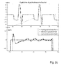
- the input and output gradients are plotted in figure 2a
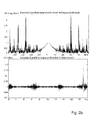
- the calculated response function is plotted in figure 2b
- the response function can be used to extrapolate the field gradients where they were not measured, as demonstrated in figure 2c .
Landscapes
- Physics & Mathematics (AREA)
- Condensed Matter Physics & Semiconductors (AREA)
- General Physics & Mathematics (AREA)
- High Energy & Nuclear Physics (AREA)
- Engineering & Computer Science (AREA)
- Signal Processing (AREA)
- Health & Medical Sciences (AREA)
- General Health & Medical Sciences (AREA)
- Nuclear Medicine, Radiotherapy & Molecular Imaging (AREA)
- Radiology & Medical Imaging (AREA)
- Spectroscopy & Molecular Physics (AREA)
- Magnetic Resonance Imaging Apparatus (AREA)
Abstract
A method of determining an actual gradient impulse response function during execution of a magnetic resonance (MR) imaging or spectroscopy sequence, wherein a main magnetic field is generated in a sample region of an MR apparatus by means of a main magnet and wherein superimposed time dependent gradient fields and radiofrequency fields in a first RF band are generated in the sample region according to a first MR sequence for forming images or spectra, the gradient fields being generated by gradient forming means of the MR apparatus operated according to a gradient forming sequence part of said first MR sequence, the MR apparatus further comprising at least one magnetic field probe. The method comprises the steps of:
- operating said at least one magnetic field probe according to a second sequence, whereby a time dependent probe signal is repeatedly acquired from each magnetic field probe during a probe acquisition time window, thus providing at least one time dependent probe signal;
- obtaining said actual gradient impulse response function by calculating an impulse response function from said at least one time dependent probe signal and from said gradient forming sequence part.
- operating said at least one magnetic field probe according to a second sequence, whereby a time dependent probe signal is repeatedly acquired from each magnetic field probe during a probe acquisition time window, thus providing at least one time dependent probe signal;
- obtaining said actual gradient impulse response function by calculating an impulse response function from said at least one time dependent probe signal and from said gradient forming sequence part.
Description
- The present invention generally relates to a method of determining an actual gradient impulse response function ("GIRF") during execution of a magnetic resonance imaging or spectroscopy sequence. This method will also be called "gradient response harvesting".
- Time-varying magnetic field gradients are essential for signal preparation and encoding in magnetic resonance imaging and spectroscopy. Most MR methods rely on highly accurate gradient time-courses for correct signal encoding and suffer from artifacts when significant deviations from the prescribed time-courses occur. In practice, effective gradient waveforms usually do differ somewhat from the ideal shapes defined in the underlying pulse sequence. These deviations are largely due to a variety of hardware imperfections including bandwidth limitations of gradient amplifiers, eddy currents induced in gradient coils and in other conducting structures of the scanner, field fluctuations caused by mechanical vibrations after gradient switching, and thermal variation in hardware components. Slight perturbations can also stem from physiologically induced fields that originate in the subject under examination or from magnetic sources and currents external to the MR system. Besides further hardware optimization, the most common ways of addressing dynamic field imperfections are precompensation of gradient waveforms and postcorrection of acquired data. Both of these options are most feasible for mechanisms of perturbation that are reproducible and can be accurately modeled (see Vannesjö SJ et al., Gradient system characterization by impulse response measurements with a dynamic field camera. Magn Reson Med 2013; 69: 583-589, and references cited therein).
- According to linear systems theory, the above mentioned approach should permit jointly representing all the response mechanisms that are linear and time-invariant (LTI). A net gradient impulse response function (GIRF) should hence incorporate all influences on the gradient waveform between the console and the magnet bore. This would include amplifier and coil characteristics as well as eddy currents and vibration-induced fields, without the need to consider individual underlying mechanisms. Knowledge of the comprehensive GIRF could form the basis of advanced pre-emphasis and serve for quality assurance purposes. It could also yield more accurate estimates of effective k-space trajectories for image reconstruction and of other encoding parameters such as b-values in diffusion imaging or gradient moments in velocity mapping. The key challenge toward this goal is determining GIRFs accurately, with sufficient bandwidth and frequency resolution, and within reasonable measurement times. Probing the GIRF must generally involve observing a system's response to given gradient input waveforms.
- For this purpose, it has been proposed to record the field evolution with a dynamic field camera, i.e. with an array of miniature NMR probes that are operated simultaneously and positioned such as to distinguish different spatial components of interest. In the work done so far, particular emphasis was placed on designing specific gradient input waveforms that are tailored to the subsequent observation with a dynamic field camera (see see Vannesjö SJ et al., Field camera measurements of gradient and shim impulse responses using frequency sweeps. Magn Reson Med 2014; 72: 570-583, and references cited therein).
- However, it would still be desirable to acquire GIRF in a manner as simple as possible and without the need of interrupting ordinary MR data acquisition.
- It is thus an object of the present invention to provide an improved, flexible and widely applicable method of determining an actual gradient impulse response function during execution of a magnetic resonance (MR) imaging or spectroscopy sequence within an ordinary MR imaging or MR spectroscopy set-up. A further, concurrent object of the present invention is to overcome the limitations and disadvantages of currently known methods and arrangements for magnetic resonance (MR) imaging or spectroscopy.
- According to one aspect of the invention, a method of determining an actual gradient impulse response function during execution of a magnetic resonance (MR) imaging or spectroscopy sequence, wherein a main magnetic field is generated in a sample region of an MR apparatus by means of a main magnet and wherein superimposed time dependent gradient fields and radiofrequency fields in a first RF band are generated in the sample region according to a first MR sequence for forming images or spectra, the gradient fields being generated by gradient forming means of the MR apparatus operated according to a gradient forming sequence part of said first MR sequence, the MR apparatus further comprising at least one magnetic field probe, each one of said magnetic field probes being located at a pre-determined position and comprising a magnetic resonance (MR) active substance, means for pulsed MR excitation of said substance and means for receiving a probe MR signal generated by said substance, wherein said pulsed MR excitation and said probe MR signal is in a second RF band that does not overlap said first RF band, comprises the steps of:
- operating said at least one magnetic field probe according to a second sequence, whereby a time dependent probe signal is repeatedly acquired from each magnetic field probe during a probe acquisition time window, thus providing at least one time dependent probe signals;
- obtaining said actual gradient impulse response function by calculating an impulse response function from said at least one time dependent probe signal and from said gradient forming sequence part.
- The above defined method may be understood as "gradient response harvesting". It is a method where the gradient responses are continuously characterized during an "ordinary" MRI or MR spectroscopy sequence. It employs MR field probes, preferably NMR field probes, which are placed in the scanner bore. The probes data is recorded repeatedly during the MR sequence. From the known input to the gradient amplifiers together with the field responses of the probes, a gradient response can be characterized. Information of several readouts can be combined to characterize the gradient system to the desired level of detail. The method does not require the field responses to be captured in a continuous or regular fashion, but allows for gaps between the measurements to wait for T2 decay and T1 recovery, and to ignore data if the field probes are dephased. The time to characterize the gradient system has to be short as compared to the time in which the gradient system changes its behavior to a desired level of detail. On this level, the system can be considered as linear and time-invariant (LTI).
- The obtained continuous gradient characterization can then be used to update the system calibration if deviations from a desired response are diagnosed. Alternatively the information may be used during the image reconstruction stage. Moreover the information might be used for quality assurance reasons (detection of broken gradient modules; characterization of long-term performance of hardware components).
- Its implementation can vary in several aspects:
- Different types of field probes can be employed, which can be optimized in terms of
- o T2
- o Nuclei
- o Droplet size
- o Number of probes
- The gradient model can be restricted to better condition the gradient response calculation. Possible parameters are
- o Frequency range
- o Time constant eddy off eddy currents
- o Time constants of oscillatory terms
- o Higher-order field terms
- o Gradient cross-terms
- Shim responses may also be measured
- MR Sequence design
- o may be unchanged
- o Additional blips may be inserted
- Time of field measurements can be adjusted to capture the parts of the MR sequence which are likely to hold the desired information content to calculate the gradient response. This may include a step where the sequence is parsed before execution and the field measurements are placed in optimized positions
- Data could be weighted by the probes signal level and could be discarded if the probes are dephased too much
- Probes may be placed near to the patient or may be farer away (e.g. in the scanner bridge)
- Update of the gradient response may be conducted in different ways. If a guaranteed time for a gradient response calculation can be asserted (e.g. by additional blips), common controllers such PID controllers may be employed. Alternatively gradient response update can be delayed until sufficient information has been gathered. Another alternative could be to only selectively update features of the gradient response (e.g. specific eddy current time constants) which might be interesting for some applications and response models.
An initial guess of the gradient response function could be e.g. a gradient response that was measured in a calibration sequence, or the response function evaluated in the last sequence. - Real-time gradient response calculation and subsequent gradient pre-emphasis update could be combined with real-time field feed feedback. In this scenario real-time gradient pre-emphasis update could cover the short term field perturbations whereas slow field perturbations (<10 Hz or <100 Hz) could be covered by the field feedback.
- A very limited implementation could also be to replace EPI phase correction.
- According to another aspect of the invention, a method of operating an MR imaging or spectroscopy apparatus, comprises the step of determining an actual gradient impulse response function according to the present invention, wherein said actual gradient impulse response function is used to update a system calibration of said apparatus.
- According to a further aspect of the invention, a method of operating an MR imaging or spectroscopy apparatus, comprises the step of determining an actual gradient impulse response function according to the present invention, wherein said actual gradient impulse response function is used for reconstruction of images or spectra obtained with said first MR sequence.
- Advantageous embodiments are defined in the dependent claims and in the description below.
- According to one embodiment (claim 2), said gradient forming sequence part is substantially periodic with a first repetition time tR1 and a minimum time gap tG between successive probe acquisition time windows is substantially larger than the sampling time required to cover the full bandwidth of the gradient forming sequence, with the provision that if said second sequence is substantially periodic with a second repetition time tR2 then said repetition times tR1 and tR2 shall be incommensurable.
- According to another embodiment (claim 3), said gradient forming sequence part is substantially periodic with a first repetition time tR1 and a minimum time gap tG between successive probe acquisition time windows is substantially larger than the sampling time required to cover the full bandwidth of the gradient forming sequence, said probe acquisition time windows being positioned in such manner as to allow for calculation of the gradient impulse response function.
- According to another embodiment (claim 4), the time gap between successive probe acquisition time windows is equal to or smaller than the sampling time required to cover the bandwidth of the gradient forming sequence. For this embodiment the gradient forming sequence part does not need to be substantially periodic.
- According to another embodiment (claim 5), said first RF band is selected for MR of 1H nuclei and said second RF band is selected for MR of 19F nuclei. For example, when using a main magnetic field of 3 T, the MR of 1H nuclei is at ∼127.8 MHz whereas the MR of 19F nuclei is at ∼120.2 MHz.
- According to another embodiment (claim 6), the MR apparatus comprises a plurality of at least four, preferably at least 16 magnetic field probes. It will be understood that the magnetic field probes shall be appropriately positioned, generally displaced from the isocenter. For example, they are evenly distributed on a sphere around the isocenter.
- Other convenient arrangements of the field probes are possible. For example, they may be rigidly mounted into a part of an MR apparatus, e.g. in a patient bed structure.
- A typical MR system has gradient ('x', 'y', 'z') amplifiers (and can have additionally multiple shim amplifiers) each having a separate input. For each gradient input, the response functions to any measured field coefficients can be calculated.
- One way this can be done is by solving the following linear problem

- Here o denotes a vector of length M holding output field coefficient values for all measured time points. I is a matrix of size M x N where each line holds the input gradient waveform that is time-shifted correspondingly to o. r denotes a vector of size N representing a discretized version of the unknown response function.
- Another, very useful way to calculate a response function is based on fitting a physically motivated model, e.g. by fitting time constants of exponential decays and oscillatory terms.
- Based on such physically motivated prior knowledge, the linear system may be constrained or regularized, which leads to an important computational simplification.
- The above mentioned and other features and objects of this invention and the manner of achieving them will become more apparent and this invention itself will be better understood by reference to the following description of embodiments of this invention taken in conjunction with the accompanying drawings, wherein
- Fig. 1a
- shows an exemplary gradient forming sequence (continuous line) and probe acquisition window (dashed line) with comparatively long duration;
- Fig. 1b
- shows the gradient forming sequence of
Fig. 1 a (continuous line) and a plurality of probe acquisition windows (dashed line) with comparatively short duration; - Fig. 2a
- shows a known gradient input function (continuous dark grey line) and measured portions of the gradient field (non-continuous black line), both expressed in mT/m as a function of time in ms;
- Fig. 2b
- shows the magnitude (in arbitrary units) of calculated response function in the frequency (Fourier) domain (upper panel, as a function of frequency in kHz) and in the time domain (lower panel, as a function of time in ms);
- Fig 2c
- shows, together with the known gradient input function (continuous dark grey line) and the measured portions of the gradient field (non-continuous black line) of
Fig. 2a , the calculated gradient field (continuous light grey line), all expressed in mT/m as a function of time in ms. - In the schematic drawing of
Fig. 1a , a substantially periodic input gradient field with a first repetition time tR1 and a probe acquisition time window with a width tP is shown. - In the schematic drawing of
Fig. 1b , a substantially periodic input gradient field with a first repetition time tR1 and a sequence of probe acquisition time windows with a width tP is shown. In this example the acquisition time windows are substantially periodic with a repetition time tR2 which means that the time gaps tG between successive time windows are constant. In the case of non-periodic sequences, the time gaps between different pairs of successive windows are variable. - An MR imaging sequence was played out at an MR system. Concurrent measurements of magnetic field responses were performed with an array of 16 NMR field probes. The actual observable of each probe is the phase of its NMR signal, which is proportional to the integral of the magnetic field magnitude at the probe position. Based on knowledge of the probe positions, the spatiotemporal field evolution is then expressed in terms of the previously chosen spatial basis functions. The resulting time-varying coefficients km (t) indicate the observed phase accumulated due to fields of the respective spatial structure. The time-derivative of the phase coefficients gives corresponding field coefficients

where y is the gyromagnetic ratio of the NMR-active nucleus in the probes. - In the present experiments the sequence repetition time was 6.3 ms. The NMR field probe data was acquired simultaneously with 16 NMR field probes (T1 = approx. T2 = approx. 110us).
- In order to retrieve field information from the NMR probes, each probe is excited by an RF pulse. Subsequently, the NMR signal that holds the field information can be acquired on a high bandwidth.
- In this experiment, a sampling time of 1 us was used.
- Due to T2 decay of the NMR probes, the NMR signal provides field information only for a limited time. After that, the probes need to be excited again. Before re-exciting the field probes, it is necessary to wait for T1 recovery and T2 relaxation of the field probes.
- In this experiment, an acquisition duration of 120us was used with a probe repetition time of 210us.
- From all acquired field probe data and the known field probe positions, field coefficients were calculated by performing a spatial expansion on chosen basis functions using the field monitoring methodology described in Barmet C et al., Magn Reson Med 2008; 60: 187-197 2008 and in Vannesjö, loc. cit. 2013.
- In this experiment, a spherical harmonic basis was chosen. Hence, the 0th order field coefficients relating to the basis '1' describe global field changes; the field coefficients relating to the basis functions 'x', 'y' and 'z' are the fields gradient. Moreover, higher-order field coefficients can be calculated.
- As mentioned further above, the response functions to any measured field coefficients can be calculated by solving the following linear problem

where o denotes a vector of length M holding output field coefficient values for all measured time points. I is a matrix of size M x N where each line holds the input gradient waveform that are time-shifted correspondingly to o.
r denotes a vector of size N representing a discretized version of the unknown response function. - For this experiment, the response function of input gradient 'x' to measured output field gradient 'x' (self-term) was calculated. The field coefficients of the MR sequence were observed over a duration of 631.2 ms. In this time output data with a total duration of 361.2 ms was acquired. The length of response function was set to 20 ms. The response function r was calculated on a bandwidth of +-50kHz (10us sample dwell), such that M = 36120 and N = 2000.
- The input and output gradients are plotted in
figure 2a , the calculated response function is plotted infigure 2b . The response function can be used to extrapolate the field gradients where they were not measured, as demonstrated infigure 2c .
Claims (8)
- A method of determining an actual gradient impulse response function during execution of a magnetic resonance (MR) imaging or spectroscopy sequence, wherein a main magnetic field is generated in a sample region of an MR apparatus by means of a main magnet and wherein superimposed time dependent gradient fields and radiofrequency fields in a first RF band are generated in the sample region according to a first MR sequence for forming images or spectra, the gradient fields being generated by gradient forming means of the MR apparatus operated according to a gradient forming sequence part of said first MR sequence, the MR apparatus further comprising at least one magnetic field probe, each one of said magnetic field probes being located at a pre-determined position and comprising a magnetic resonance (MR) active substance, means for pulsed MR excitation of said substance and means for receiving a probe MR signal generated by said substance, wherein said pulsed MR excitation and said probe MR signal is in a second RF band that does not overlap said first RF band, the method comprising the steps of:- operating said at least one magnetic field probe according to a second sequence, whereby a time dependent probe signal is repeatedly acquired from each magnetic field probe during a probe acquisition time window, thus providing at least one time dependent probe signal;- obtaining said actual gradient impulse response function by calculating an impulse response function from said at least one time dependent probe signal and from said gradient forming sequence part.
- The method according to claim 1, wherein said gradient forming sequence part is substantially periodic with a first repetition time tR1 and a minimum time gap tG between successive probe acquisition time windows is substantially larger than the sampling time required to cover the full bandwidth of the gradient forming sequence, with the provision that if said second sequence is substantially periodic with a second repetition time tR2 then said repetition times tR1 and tR2 shall be incommensurable.
- The method according to claim 1, wherein said gradient forming sequence part is substantially periodic with a first repetition time tR1 and a minimum time gap tG between successive probe acquisition time windows is substantially larger than the sampling time required to cover the full bandwidth of the gradient forming sequence, said probe acquisition time windows being positioned in such manner as to allow for calculation of the gradient.
- The method according to claim 1, wherein the time gap between successive probe acquisition time windows is equal to or smaller than the sampling time required to cover the bandwidth of the gradient forming sequence.
- The method according to one of claims 1 to 4, wherein said first RF band is selected for MR of 1H nuclei and wherein said second RF band is selected for MR of 19F nuclei.
- The method according to one of claims 1 to 5, wherein the MR apparatus comprises a plurality of at least four, preferably at least 16 magnetic field probes.
- A method of operating an MR imaging or spectroscopy apparatus, comprising the step of determining an actual gradient impulse response function according to one of claims 1 to 6, wherein said actual gradient impulse response function is used to update a system calibration of said apparatus.
- A method of operating an MR imaging or spectroscopy apparatus, comprising the step of determining an actual gradient impulse response function according to one of claims 1 to 6, wherein said actual gradient impulse response function is used for reconstruction of images or spectra obtained with said first MR sequence.
Priority Applications (5)
| Application Number | Priority Date | Filing Date | Title |
|---|---|---|---|
| EP15167449.6A EP3093682A1 (en) | 2015-05-12 | 2015-05-12 | A method of determining a gradient impulse response function during execution of a magnetic resonance imaging or spectroscopy sequence |
| ES16722878T ES2871174T3 (en) | 2015-05-12 | 2016-05-12 | A procedure for determining a gradient impulse response function during the execution of a spectroscopy or magnetic resonance imaging sequence |
| PCT/EP2016/060740 WO2016180938A1 (en) | 2015-05-12 | 2016-05-12 | A method of determining a gradient impulse response function during execution of a magnetic resonance imaging or spectroscopy sequence |
| US15/573,284 US10379190B2 (en) | 2015-05-12 | 2016-05-12 | Method of determining a gradient impulse response function during execution of a magnetic resonance imaging or spectroscopy sequence |
| EP16722878.2A EP3295203B1 (en) | 2015-05-12 | 2016-05-12 | A method of determining a gradient impulse response function during execution of a magnetic resonance imaging or spectroscopy sequence |
Applications Claiming Priority (1)
| Application Number | Priority Date | Filing Date | Title |
|---|---|---|---|
| EP15167449.6A EP3093682A1 (en) | 2015-05-12 | 2015-05-12 | A method of determining a gradient impulse response function during execution of a magnetic resonance imaging or spectroscopy sequence |
Publications (1)
| Publication Number | Publication Date |
|---|---|
| EP3093682A1 true EP3093682A1 (en) | 2016-11-16 |
Family
ID=53175342
Family Applications (2)
| Application Number | Title | Priority Date | Filing Date |
|---|---|---|---|
| EP15167449.6A Ceased EP3093682A1 (en) | 2015-05-12 | 2015-05-12 | A method of determining a gradient impulse response function during execution of a magnetic resonance imaging or spectroscopy sequence |
| EP16722878.2A Active EP3295203B1 (en) | 2015-05-12 | 2016-05-12 | A method of determining a gradient impulse response function during execution of a magnetic resonance imaging or spectroscopy sequence |
Family Applications After (1)
| Application Number | Title | Priority Date | Filing Date |
|---|---|---|---|
| EP16722878.2A Active EP3295203B1 (en) | 2015-05-12 | 2016-05-12 | A method of determining a gradient impulse response function during execution of a magnetic resonance imaging or spectroscopy sequence |
Country Status (4)
| Country | Link |
|---|---|
| US (1) | US10379190B2 (en) |
| EP (2) | EP3093682A1 (en) |
| ES (1) | ES2871174T3 (en) |
| WO (1) | WO2016180938A1 (en) |
Families Citing this family (5)
| Publication number | Priority date | Publication date | Assignee | Title |
|---|---|---|---|---|
| RU2736557C2 (en) * | 2016-10-10 | 2020-11-18 | Конинклейке Филипс Н.В. | Mapping of gradient impulse response function |
| DE102020209382A1 (en) * | 2020-07-24 | 2022-01-27 | Siemens Healthcare Gmbh | Method for recording measurement data using a magnetic resonance system with a correction of the k-space trajectories used |
| DE102020209787A1 (en) | 2020-08-04 | 2022-02-10 | Siemens Healthcare Gmbh | Continuous trajectory correction in magnetic resonance imaging |
| DE102022200185A1 (en) | 2021-12-30 | 2023-07-06 | Siemens Healthcare Gmbh | Avoidance of artefacts in measurement data recorded by means of a magnetic resonance system |
| CN118037879A (en) * | 2022-11-02 | 2024-05-14 | 脉冲视觉(北京)科技有限公司 | Time series signal processing and image reconstruction method, device, equipment and medium |
Citations (1)
| Publication number | Priority date | Publication date | Assignee | Title |
|---|---|---|---|---|
| WO2012143574A1 (en) * | 2011-04-22 | 2012-10-26 | Eidgenössische Technische Hochschule (ETH) | Dynamic field camera arrangement for magnetic resonance applications and methods for operating the same |
-
2015
- 2015-05-12 EP EP15167449.6A patent/EP3093682A1/en not_active Ceased
-
2016
- 2016-05-12 US US15/573,284 patent/US10379190B2/en active Active
- 2016-05-12 ES ES16722878T patent/ES2871174T3/en active Active
- 2016-05-12 EP EP16722878.2A patent/EP3295203B1/en active Active
- 2016-05-12 WO PCT/EP2016/060740 patent/WO2016180938A1/en not_active Ceased
Patent Citations (1)
| Publication number | Priority date | Publication date | Assignee | Title |
|---|---|---|---|---|
| WO2012143574A1 (en) * | 2011-04-22 | 2012-10-26 | Eidgenössische Technische Hochschule (ETH) | Dynamic field camera arrangement for magnetic resonance applications and methods for operating the same |
Non-Patent Citations (7)
| Title |
|---|
| BARMET C ET AL., MAGN RESON MED, vol. 60, 2008, pages 187 - 197 |
| BARMET C ET AL: "Concurrent higher-order field monitoring for routine head MRI: an integrated heteronuclear setup", PROCEEDINGS OF THE INTERNATIONAL SOCIETY FOR MAGNETIC RESONANCE IN MEDICINE, ISMRM, 18TH SCIENTIFIC MEETING AND EXHIBITION, STOCKHOLM, SWEDEN, 1-7 MAY 2010, 17 April 2010 (2010-04-17), pages 216, XP040613508 * |
| DIETRICH BE ET AL: "An autonomous system for continuous field monitoring with interleaved probe sets", PROCEEDINGS OF THE INTERNATIONAL SOCIETY FOR MAGNETIC RESONANCE IN MEDICINE, ISMRM, 19TH ANNUAL MEETING AND EXHIBITION, MONTREAL, QUEBEC, 7-13 MAY 2011, 23 April 2011 (2011-04-23), pages 1842, XP040618502 * |
| GRAEDEL NN ET AL: "Image reconstruction using the gradient impulse response for trajectory prediction", PROCEEDINGS OF THE INTERNATIONAL SOCIETY FOR MAGNETIC RESONANCE IN MEDICINE, ISMRM, 21ST ANNUAL MEETING AND EXHIBITION, SALT LAKE CITY, UTAH, USA, 20-26 APRIL 2013, 7 April 2013 (2013-04-07), pages 552, XP040628151 * |
| S. JOHANNA VANNESJO ET AL: "Field camera measurements of gradient and shim impulse responses using frequency sweeps", MAGNETIC RESONANCE IN MEDICINE., vol. 72, no. 2, 16 September 2013 (2013-09-16), US, pages 570 - 583, XP055230711, ISSN: 0740-3194, DOI: 10.1002/mrm.24934 * |
| VANNESJ6 SJ ET AL.: "Gradient system characterization by impulse response measurements with a dynamic field camera", MAGN RESON MED, vol. 69, 2013, pages 583 - 589 |
| VANNESJ6 SJ: "Field camera measurements of gradient and shim impulse responses using frequency sweeps", MAGN RESON MED, vol. 72, 2014, pages 570 - 583 |
Also Published As
| Publication number | Publication date |
|---|---|
| US20180136298A1 (en) | 2018-05-17 |
| EP3295203B1 (en) | 2021-04-14 |
| US10379190B2 (en) | 2019-08-13 |
| ES2871174T3 (en) | 2021-10-28 |
| WO2016180938A1 (en) | 2016-11-17 |
| EP3295203A1 (en) | 2018-03-21 |
Similar Documents
| Publication | Publication Date | Title |
|---|---|---|
| US5770943A (en) | Method for measuring and compensating for spatially and temporally varying magnetic fields induced by eddy currents | |
| Vannesjo et al. | Gradient system characterization by impulse response measurements with a dynamic field camera | |
| Rahmer et al. | Rapid acquisition of the 3D MRI gradient impulse response function using a simple phantom measurement | |
| US7141970B2 (en) | Magnetic resonance imaging device | |
| US10379190B2 (en) | Method of determining a gradient impulse response function during execution of a magnetic resonance imaging or spectroscopy sequence | |
| EP3044604B1 (en) | Metal resistant mr imaging | |
| EP0100183B1 (en) | Nuclear magnetic resonance method and apparatus | |
| US10557908B2 (en) | Magnetic field monitoring of spiral echo train imaging | |
| WO2016180983A1 (en) | Multi-echo mri with correction of concomitant gradient-induced phase errors | |
| US11585884B2 (en) | Continual trajectory correction in magnetic resonance imaging | |
| JP2000185029A (en) | Method for detecting eddy currents in a nuclear spin resonance apparatus | |
| Nussbaum et al. | Thermal variation in gradient response: measurement and modeling | |
| US7378845B2 (en) | NMR methods for measuring fluid flow rates | |
| US6127826A (en) | EPI image based long term eddy current pre-emphasis calibration | |
| US20180113184A1 (en) | T2-weighted mr imaging with elimination of non-t2-weighted signal contibutions | |
| JP2002052007A (en) | Magnetic resonance imaging apparatus | |
| KR20190050717A (en) | System and method for magnetic resonance imaging an object with a plurality of readout gradient amplitudes | |
| JP2000279390A (en) | Magnetic resonance imaging device | |
| US20020050816A1 (en) | MR imaging method, phase error measuring method, and MRI apparatus | |
| US9915713B2 (en) | Determining positions of a magnetic field probe in a magnetic resonance measurement | |
| EP3447519A1 (en) | A method and apparatus for gradient delay measurement of a magnetic resonance imaging system | |
| US7323872B1 (en) | Method and apparatus of directly measuring cross-axis eddy currents for MR scanner calibration | |
| US10302720B2 (en) | Method and apparatus for determining dephasing factors in magnetic resonance imaging and spectroscopy | |
| US12313717B2 (en) | Avoidance of artifacts in measurement data captured using a magnetic resonance system | |
| EP4462147A1 (en) | Mr imaging using cest contrast enhancement |
Legal Events
| Date | Code | Title | Description |
|---|---|---|---|
| PUAI | Public reference made under article 153(3) epc to a published international application that has entered the european phase |
Free format text: ORIGINAL CODE: 0009012 |
|
| AK | Designated contracting states |
Kind code of ref document: A1 Designated state(s): AL AT BE BG CH CY CZ DE DK EE ES FI FR GB GR HR HU IE IS IT LI LT LU LV MC MK MT NL NO PL PT RO RS SE SI SK SM TR |
|
| AX | Request for extension of the european patent |
Extension state: BA ME |
|
| STAA | Information on the status of an ep patent application or granted ep patent |
Free format text: STATUS: THE APPLICATION HAS BEEN REFUSED |
|
| 18R | Application refused |
Effective date: 20161216 |