EP3093617A1 - A system for detection of foundation movement in a wind turbine - Google Patents
A system for detection of foundation movement in a wind turbine Download PDFInfo
- Publication number
- EP3093617A1 EP3093617A1 EP16168909.6A EP16168909A EP3093617A1 EP 3093617 A1 EP3093617 A1 EP 3093617A1 EP 16168909 A EP16168909 A EP 16168909A EP 3093617 A1 EP3093617 A1 EP 3093617A1
- Authority
- EP
- European Patent Office
- Prior art keywords
- wind turbine
- turbine tower
- displacement
- sensors
- plumb
- Prior art date
- Legal status (The legal status is an assumption and is not a legal conclusion. Google has not performed a legal analysis and makes no representation as to the accuracy of the status listed.)
- Granted
Links
Images



Classifications
-
- G—PHYSICS
- G01—MEASURING; TESTING
- G01C—MEASURING DISTANCES, LEVELS OR BEARINGS; SURVEYING; NAVIGATION; GYROSCOPIC INSTRUMENTS; PHOTOGRAMMETRY OR VIDEOGRAMMETRY
- G01C15/00—Surveying instruments or accessories not provided for in groups G01C1/00 - G01C13/00
- G01C15/10—Plumb lines
-
- G—PHYSICS
- G01—MEASURING; TESTING
- G01B—MEASURING LENGTH, THICKNESS OR SIMILAR LINEAR DIMENSIONS; MEASURING ANGLES; MEASURING AREAS; MEASURING IRREGULARITIES OF SURFACES OR CONTOURS
- G01B21/00—Measuring arrangements or details thereof, where the measuring technique is not covered by the other groups of this subclass, unspecified or not relevant
- G01B21/22—Measuring arrangements or details thereof, where the measuring technique is not covered by the other groups of this subclass, unspecified or not relevant for measuring angles or tapers; for testing the alignment of axes
- G01B21/24—Measuring arrangements or details thereof, where the measuring technique is not covered by the other groups of this subclass, unspecified or not relevant for measuring angles or tapers; for testing the alignment of axes for testing alignment of axes
-
- G—PHYSICS
- G01—MEASURING; TESTING
- G01C—MEASURING DISTANCES, LEVELS OR BEARINGS; SURVEYING; NAVIGATION; GYROSCOPIC INSTRUMENTS; PHOTOGRAMMETRY OR VIDEOGRAMMETRY
- G01C15/00—Surveying instruments or accessories not provided for in groups G01C1/00 - G01C13/00
- G01C15/002—Active optical surveying means
-
- G—PHYSICS
- G01—MEASURING; TESTING
- G01M—TESTING STATIC OR DYNAMIC BALANCE OF MACHINES OR STRUCTURES; TESTING OF STRUCTURES OR APPARATUS, NOT OTHERWISE PROVIDED FOR
- G01M5/00—Investigating the elasticity of structures, e.g. deflection of bridges or air-craft wings
- G01M5/0025—Investigating the elasticity of structures, e.g. deflection of bridges or air-craft wings of elongated objects, e.g. pipes, masts, towers or railways
-
- G—PHYSICS
- G01—MEASURING; TESTING
- G01M—TESTING STATIC OR DYNAMIC BALANCE OF MACHINES OR STRUCTURES; TESTING OF STRUCTURES OR APPARATUS, NOT OTHERWISE PROVIDED FOR
- G01M5/00—Investigating the elasticity of structures, e.g. deflection of bridges or air-craft wings
- G01M5/0083—Investigating the elasticity of structures, e.g. deflection of bridges or air-craft wings by measuring variation of impedance, e.g. resistance, capacitance, induction
-
- G—PHYSICS
- G01—MEASURING; TESTING
- G01C—MEASURING DISTANCES, LEVELS OR BEARINGS; SURVEYING; NAVIGATION; GYROSCOPIC INSTRUMENTS; PHOTOGRAMMETRY OR VIDEOGRAMMETRY
- G01C9/00—Measuring inclination, e.g. by clinometers, by levels
- G01C9/02—Details
- G01C9/06—Electric or photoelectric indication or reading means
-
- Y—GENERAL TAGGING OF NEW TECHNOLOGICAL DEVELOPMENTS; GENERAL TAGGING OF CROSS-SECTIONAL TECHNOLOGIES SPANNING OVER SEVERAL SECTIONS OF THE IPC; TECHNICAL SUBJECTS COVERED BY FORMER USPC CROSS-REFERENCE ART COLLECTIONS [XRACs] AND DIGESTS
- Y02—TECHNOLOGIES OR APPLICATIONS FOR MITIGATION OR ADAPTATION AGAINST CLIMATE CHANGE
- Y02E—REDUCTION OF GREENHOUSE GAS [GHG] EMISSIONS, RELATED TO ENERGY GENERATION, TRANSMISSION OR DISTRIBUTION
- Y02E10/00—Energy generation through renewable energy sources
- Y02E10/70—Wind energy
- Y02E10/72—Wind turbines with rotation axis in wind direction
Definitions
- the present invention relates in a first aspect to a monitoring system for monitoring displacement of a wind turbine tower.
- the present invention relates to a device comprising the system according to the first aspect of the present invention.
- the present invention relates to a use of a system according to the first aspect or the use of a device according to the second aspect for monitoring displacement of a wind turbine tower.
- the present invention relates to a method for monitoring displacement of a wind turbine tower.
- the present invention relates to a wind turbine tower comprising the system according to the first aspect or comprising a device according to the second aspect.
- the present invention relates to a wind turbine comprising the wind turbine tower according to the fifth aspect.
- a typical wind turbine comprises an elongate tower attached to a foundation that is intended for transferring vertical loads as well as horizontal dynamic loads of the wind turbine to the ground. In order to prevent angular deflection of the foundations, a robust design of the foundations is required.
- the load of the foundation can reach a critical level due to the additional load caused by the horizontal dynamic loads of the wind turbine during operation of the wind turbine. It is a significant problem if the load of the foundation is so large that the displacement between a foundation member and a base member attached to the foundation member exceeds a critical displacement limit.
- FR 2 314 478 A1 an inclinometer having adjustable sensitivity for measuring deviations from a vertical direction of an architectural structure.
- the inclinometer comprises a hanging mass being suspended by a flexible strip which is fixed to an upper base. Strain gauges arranged in the vicinity of the flexible strip act as sensors for determining an inclination of the hanging mass.
- the mass is contained in oil. The level of the oil determines the sensitivity of the inclinometer.
- FR 2 314 478 A1 does not disclose that the inclinometer comprises a control unit being configured to receive displacement date from the strain gauges.
- WO 2013/167128 A1 discloses a monitoring system configured to monitor a vertical displacement between a foundation member and a base member attached to the foundation member.
- the monitoring system comprises: three sensors adapted to measure displacement between the foundation member and the base member of a wind turbine tower, wherein each of the three sensors are arranged on a vertically extending rod fixed to the foundation member.
- a control unit is configured to receive displacement data from the sensors and to send the received displacement data to an external unit
- laser sensors may be sensitive towards distances in case insects or other small animals originating from the environment settle on the plate being sensed by the laser sensor. In such a case, the laser sensor will sense a false distance and thus provide erroneous displacement data.
- the present invention relates in its first aspect to a monitoring system for monitoring displacement of a wind turbine tower, said monitoring system comprises:
- the present invention relates to a device for mounting on an inner wall of a wind turbine tower and for monitoring displacement of said wind turbine tower; said device comprises a monitoring system according to the first aspect of the present invention;
- the present invention relates to the use of a system according to the first aspect of the present invention; or of a device according to the first aspect of the present invention for monitoring displacement of a wind turbine tower.
- the present invention relates to a method for monitoring a displacement of a wind turbine tower, said method comprises:
- the present invention relates to wind turbine tower comprising a system according to according to the first aspect of the present invention; or comprising a device according to the second aspect of the present invention
- the present invention relates to a wind turbine comprising a wind turbine tower according to the fifth aspect of the present invention
- the present invention in its various aspects provides for a monitoring system, devices, uses and methods which are more reliable, less prone to environmental impacts and impact due to vandalism, which is in essence maintenance free and easier to install.
- the present invention relates to a monitoring system for monitoring displacement of a wind turbine tower, said monitoring system comprises:
- each plumb bob By arranging each plumb bob in the vicinity of a sensor in a specific distance in a sensing direction of that sensor, it will be possible to monitor any displacement of that plumb bob in relation to that specific sensor. By making sure that the sensing directions of the two or more sensing direction are not parallel, it is ensured that a displacement can be monitored in relation to any direction.
- the suspension means are having a specifically short length and by ensuring that the plumb bob(s) is/are suspended in a lower part of the wind turbine tower one can make sure that the monitoring system is monitoring a displacement between a foundation member and a base member, rather than just monitoring vibrations or bends of the wind turbine tower.
- a foundation member may be any type of foundation, e.g. a concrete foundation for a wind turbine.
- the base member may be any base member of the wind turbine tower construction. Under normal operation conditions of the wind turbine, the base member is connected to the foundation member.
- the term "displacement of a wind turbine tower” shall preferably be interpreted to specifically mean a displacement or deflection of the wind turbine tower which will result in a situation in which the turbine tower will have an inclination or slope relative to the vertical direction, which is different from the original and/or intended vertical direction.
- the term "displacement of a wind turbine tower” shall be interpreted to mean a displacement between a foundation member and a base member of a wind turbine tower.
- one or more of said one or more plumb bobs at least partly comprising a cylindrical sensing surface, wherein said plumb bob is configured to be suspended in such a way that the direction of gravity is parallel to an axial direction of the cylindrical surface when being suspended in a rest position.
- cylindrical plumb bobs is advantageous in some embodiments, for example where one plumb bob and three sensors are being used.
- a rest position shall be interpreted as a position in which the wind turbine tower is not displaced in any direction and in which there is no displacement between a foundation member and a base member of the wind turbine tower.
- one or more of said one or more plumb bobs at least partly comprises two planar sensing surfaces, said two planar sensing surfaces preferably being perpendicular to each other.
- Such an embodiment is advantageous in case one plumb bob and two sensors are being used in the monitoring system.
- the number of plumb bobs being 1, 2, 3 or 4.
- the number of sensors being 2, 3, 4 or 5.
- the angle between sensing direction of any two of said two or more sensors is independently selected from the range of 65 - 140°, such as 70 - 135°, for example 75 - 130°, e.g. 80 - 125°, such as 85 - 120°, for example 90 - 115°, e.g. 95 - 110° or 100 - 105°.
- said system comprises one and only one plumb bob; and said system comprises three sensors which are being arranged in an equilateral triangle around said plumb bob when being arranged in a rest position.
- said system comprises one and only one plumb bob; and two sensors.
- said suspension means independently comprising: a string or a rod; or a combination of a string and a rod; such as an upper rod and a lower string, or an upper string and a lower rod; for suspending one or more of said one or more plumb bobs.
- one or more of said one or more sensors independently being selected from the group comprising an inductive sensor, a laser sensor or a magnetic sensor.
- the length of the suspension means being adjusted so as to provide radius of pivotally movement of the plumb bob of 0.5 - 8.0 m, such as 1.0 - 7.5 m, for example 1.5 - 7.0 m, e.g. 2.0 - 6.5 m, for example 2.5 - 6.0 m, such as 3.0 - 5.5 mm, for example 3.5 - 5.0 m or 4.0 - 5.0 m.
- radius of pivotally movement of the plumb bob shall be construed to mean the distance from the fixing point of the suspension means to a point on the sensing surface of the plumb bob being sensed by a sensor.
- the system is configured in such a way that the parameter(s) representing displacement of a wind turbine tower and to be reported to an external unit relate(s) to magnitude of movement and/or direction of movement.
- said system furthermore comprising a container comprising a liquid and being configured to at least partly accommodate a lower part of one or more of said one or more plumb bobs in order to dampen any movements of the plumb bob being of a vibrational nature.
- Such a set-up comprising container with a liquid will allow filtering off any vibrational movement of the plumb bob which do not relate to any displacement between a foundation member and a base member of the wind turbine tower.
- the viscosity of said liquid is selected from the range of 50-120 mPa ⁇ s, such as 55 - 115 mPa ⁇ s, for example 60 - 110 mPa ⁇ s, e.g. 65 - 105 mPa ⁇ s, such as 70 - 100 mPa ⁇ s, such as 75 - 95 mPa ⁇ s, for example 80 - 90 mPa ⁇ s.
- Such liquid may be selected amongst mineral oil or synthetic oils or mixtures thereof, optionally also comprising one or more diluters or solvents.
- said system is configured to automatically reporting to an external unit, an alert in case a predetermined alert criteria is meet; said alert criteria optionally relating to a specific magnitude of displacement of a wind turbine tower.
- Such a system allows an operator of a wind turbine to take action in case a critical magnitude of displacement of a wind turbine tower is encountered.
- said external unit being an internet server adapted to receive and store said parameter(s) representing displacement of a wind turbine tower.
- control unit is configured to be reachable remotely via an Internet Protocol connection (IP connection), UMTS (Universal Mobile Telecommunications System) connection, or via a fiber optic network.
- IP connection Internet Protocol connection
- UMTS Universal Mobile Telecommunications System
- This embodiment ensures the monitoring of the displacement of a wind turbine tower anywhere which provides access to such connections.
- said system further comprising one or more sensor mounting brackets for mounting said two or more sensors.
- Mounting brackets for the sensors ensure sturdy mounting of the sensors and hence provides for accurate measurements.
- said system further comprising one or more brackets for fixation of said one or more suspension means.
- Mounting brackets for the suspension means ensure a correct and optimum location of the suspended plumb bobs and hence provides for accurate measurements.
- the one or more of said two or more sensors comprises position adjustment means for adjustment or calibration of the position of said sensors, said adjustment means optionally being configured to allow adjustment or calibration in one, two or three dimensions.
- This system ensures fast and easy set-up and calibration of the sensors and the monitoring system per se.
- the present invention relates to a device for mounting on an inner wall of a wind turbine tower and for monitoring displacement of said wind turbine tower; wherein said device comprises a monitoring system according to the first aspect of the present invention;
- Such a device ensures easy mounting and set-up of the monitoring system. Further, such a device ensures that no unauthorized access to the delicate monitoring system is available once mounted on an inner wall of a wind turbine tower.
- said housing comprises one or more mounting means for mounting said housing onto an inner wall of a wind turbine tower.
- said one or more of said one or more mounting means comprises one or more magnets.
- said housing is a closed housing comprising one or more inspection hatches for providing access to the interior of said housing.
- Inspection hatches for providing access to the interior of said housing ensures that the monitoring system housed within the housing may be easily inspected.
- said housing comprises:
- This design of the device ensures easy mounting and set-up of the monitoring system and at the same time allows enclosure of one or more plumb bods being suspended in a suspension means having relatively long extension.
- the present invention relates to the use of a system according to the first aspect of the present invention or of a device according to the second aspect of the present invention for monitoring displacement of a wind turbine tower.
- said use relates to monitoring a displacement between a base member and a foundation member of a wind turbine tower.
- This embodiment ensures monitoring of the integrity of the connection between a base member and a foundation member of a wind turbine tower.
- the present invention relates to a method for monitoring a displacement of a wind turbine tower, said method comprises:
- said method automatically reports an alert in case a predetermined alert criterion is meet; said alert criteria optionally relating to a specific magnitude of displacement of a wind turbine tower.
- Such a method allows an operator of a wind turbine to take action in case a critical magnitude of displacement of a wind turbine tower is encountered.
- said method being performed by using a system according to the first aspect of the present invention or by using a device according to the second aspect of the present invention.
- the present invention relates to a wind turbine tower comprising a system according to the first aspect of the present invention or comprising a device according to the second aspect of the present invention
- said system or said device being arranged in a lower part of said wind turbine tower, such as at a height of 30 % or lower of the total height of the wind turbine tower, for example at a height of 25 % or lower of the total height of the wind turbine tower, e.g. at a height of 20 % or lower of the total height of the wind turbine tower, such as at a height of 15% or lower of the total height of the wind turbine tower, for example at a height of 10 % or lower of the total height of the wind turbine tower or at a height of 5 % or lower of the total height of the wind turbine tower.
- the sensors and the plumb bob(s) are being arranged in a lower part of the wind turbine tower, such as at a lower 0.5 - 5.0 m of the wind turbine tower, such as at a lower 1.0 - 4.5 m of the wind turbine tower, for example at a lower 1.5 - 4.0 m of the wind turbine tower, such as at a lower 2.0 - 3.5 m of the wind turbine tower, or at a lower 2.5 - 3.0 m of the wind turbine tower.
- the present invention relates to a wind turbine comprising a wind turbine tower according to the fifth aspect of the present invention.
- FIG. 1 is a cross-sectional view of a monitoring system 100 according to the first aspect of the present invention and being installed at an inner wall 34 of a wind turbine tower 2,300.
- the monitoring system comprises:
- the plumb bobs 4 is suspended in suspension means 10 from a point above in a fixing point 38.
- the system furthermore comprises two sensors 14,14', each being configured to sense, in a specific sensing direction 16,16', a distance to the plumb bob, and thereby provide a displacement data.
- the sensors 14,14' being arranged in a sensing vicinity of a plumb bob.
- the monitoring system illustrated in Fig. 1 furthermore comprises a control unit 18 which is configured to receive said displacement data from two or more of said sensors.
- the sensors 14,14' are connected to the control unit 18 via connecting wires 60.
- the plumb bob 4 attains a rest position which is located vertically below the fixing point 38 for the suspension means 10.
- the suspension means is suspended from a bracket 32.
- the rest position of the plumb bob 4 resting in a rest situation will imply that the sensors 14,14' will sense the sensing distance to the sensing surfaces 12,12' and the control unit will optionally be configured to interpret these sensing distances to a displacement of the wind turbine tower 2,300 of zero (0).
- the plumb bob In case the wind turbine tower is subjected to a displacement, in such a way that the wind turbine tower is not any longer vertically arranged, the plumb bob will continuously be vertically suspended in the suspension means from the fixing point 38. However, in such a situation, the plumb bob will have moved in relation to the sensors 14,14'. Accordingly, in such a displacement situation, at least one of the sensors 14,14' will sense a different sensing direction commensurate with degree of displacement of the wind turbine tower.
- control unit will optionally be configured to interpret these altered sensing distances to a displacement of the wind turbine tower 2,300 which is non-zero.
- Such a non-zero displacement of the wind turbine tower 2,300 may subsequently be reported to the external unit 20.
- the external unit 20 is in the figures depicted as being located in the vicinity to the turbine tower. However, in reality the external unit 20 may be located at a distant location.
- the suspension means 10 may comprise a string 22 or a rod 24 or a combination thereof.
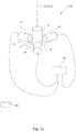
- Fig. 2a is a perspective view illustrating an alternative configuration of a plumb bob 4 and three associated sensors 14,14',14" according to one embodiment of the first aspect of the present invention.
- the plumb bob 4 is suspended so as to be located in the center of an equilateral triangle when said plumb bob being arranged in a rest position.
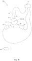
- Fig. 2b is a plane view seen from above illustrating the configuration of a plumb bob and three associated sensors of Fig. 2a .
- Fig. 2b shows that the plumb bob 4 comprises a sensing surface 12.
- Each sensor 14.14',14" will sense in a specific sensing direction 16,16',16" towards the sensing surface 12 of the plumb bob 4. It is noted that the sensing directions 16,16',16" are mutually non-parallel.
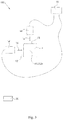
- Fig. 3 is a plane view seen from above and illustrating the configuration of a plumb bob and two associated sensors according to one embodiment of the first aspect of the present invention.
- Fig. 3 shows that the plumb bob 4 comprises two sensing surfaces 12,12'. Each sensor 14.14' will sense in a specific sensing direction 16,16' towards the sensing surface 12,12 of the plumb bob 4. It is noted that the sensing directions 16,16'are mutually perpendicular.
- Fig. 4 is a plane view seen from above and illustrating the configuration of two plumb bobs 4,4' and two associated sensors 14,14' according to one embodiment of the first aspect of the present invention.
- Fig. 4 shows that the plumb bob 4 comprises a sensing surface 12 and that the plumb bod 4' comprises a sensing surface 12'.
- Each sensor 14,14' will sense in a specific sensing direction 16,16' towards the sensing surface 12,12 of one of the plumb bobs 4, 4'. It is noted that the sensing directions 16,16' are mutually perpendicular. Accordingly, one sensor 14 will sense a displacement in one direction 16 and the other sensor 14' will sense a displacement in a direction16' which is perpendicular to the sensing direction 16.
- Fig. 5 is a side view illustrating the principle of damping of vibration movement of a plumb bob 4 by submerging it into a liquid.
- the plumb bob 4 comprises two sensing surfaces 12, 12'.
- Two sensors 14,14' are each individually sensing a distance to a specific sensing surface 12.12' of the plumb bob.
- the plumb bob being partly submerged into a liquid 28 contained in a container 26.
- Fig. 6 illustrates one embodiment of a device 200 according to the second aspect of the present invention.
- the device 200 is for mounting on an inner wall 34 of a wind turbine tower 2,300 and for monitoring displacement of said wind turbine tower.
- the device 200 comprises the monitoring system according to the first aspect of the present invention.
- the plumb bob 4 and the three sensors 14,14',14" are being enclosed within a housing 36.
- the housing 36 comprises a lower part 46 comprising said plumb s bob 4 and three sensors 14,14', 14".
- the housing 36 furthermore comprises a tubular upper part 48 extending in a vertical direction from an opening 50 in an upper wall 52 of the lower part 46 of the housing.
- the suspension means 10 are being pivotally fixed at an fixing point 38 at an upper part 54 of said tubular upper part 48, thereby allowing said tubular upper part to accommodate said suspension means 10.
- the device 200 allows for easy and fast installation of the system contained therein. Furthermore, as the device is enclosed in an enclosure or housing, the delicate and sensitive nature of the sensors and the sensing mechanism in general can be kept isolated from the interior of the wind turbine tower thereby avoiding a technician's unintentional touching and modification of the calibration of the system.
- the device 200 comprises one or more mounting means 40 for easy installation onto an inner wall of the wind turbine tower 2,300. It is preferred that such mounting means comprises one or more magnets.
- the housing 36 is a closed housing optionally comprising one or more inspection hatches 42 for providing access to the interior 44 of said housing 36.
Landscapes
- Physics & Mathematics (AREA)
- General Physics & Mathematics (AREA)
- Engineering & Computer Science (AREA)
- Aviation & Aerospace Engineering (AREA)
- Radar, Positioning & Navigation (AREA)
- Remote Sensing (AREA)
- Wind Motors (AREA)
- Length Measuring Devices With Unspecified Measuring Means (AREA)
Abstract
- one or more plumb bobs (4,4') each comprising an upper part (6) and a lower part (8); each plumb bob being configured to be pivotally suspended at its upper part, via suspension means (10), from a point above so as to attain a rest position in a rest situation; each said plumb bobs comprising one or more sensing surfaces (12,12');
- one or more suspension means (10) for suspending said one or more plumb bobs (4);
- two or more sensors (14,14', 14"), each being configured to sense, in a specific sensing direction (16,16',16"), a distance to a plumb bob, and thereby provide a displacement data;
wherein at least two of said two or more sensors (14,14',14") being arranged in a sensing vicinity of a plumb bob;
wherein at least two of said specific sensing directions (16,16',16") are not being parallel to each other;
wherein said monitoring system furthermore comprises a control unit (18) configured to receive said displacement data from two or more of said sensors; and
wherein said system furthermore comprises means for reporting to an external unit (20), parameter(s) representing displacement of a wind turbine tower.
Description
- The present invention relates in a first aspect to a monitoring system for monitoring displacement of a wind turbine tower. In a second aspect the present invention relates to a device comprising the system according to the first aspect of the present invention. In a third aspect the present invention relates to a use of a system according to the first aspect or the use of a device according to the second aspect for monitoring displacement of a wind turbine tower. In a third aspect the present invention relates to a method for monitoring displacement of a wind turbine tower. In a fifth aspect the present invention relates to a wind turbine tower comprising the system according to the first aspect or comprising a device according to the second aspect. In a sixth aspect the present invention relates to a wind turbine comprising the wind turbine tower according to the fifth aspect.
- Many engineering constructions comprise a foundation member connecting a tower structure to the ground. One example of such construction is a wind turbine. A typical wind turbine comprises an elongate tower attached to a foundation that is intended for transferring vertical loads as well as horizontal dynamic loads of the wind turbine to the ground. In order to prevent angular deflection of the foundations, a robust design of the foundations is required.
- In operation, the load of the foundation can reach a critical level due to the additional load caused by the horizontal dynamic loads of the wind turbine during operation of the wind turbine. It is a significant problem if the load of the foundation is so large that the displacement between a foundation member and a base member attached to the foundation member exceeds a critical displacement limit.
- In
FR 2 314 478 A1 FR 2 314 478 A1 -
WO 2013/167128 A1 discloses a monitoring system configured to monitor a vertical displacement between a foundation member and a base member attached to the foundation member. The monitoring system comprises: three sensors adapted to measure displacement between the foundation member and the base member of a wind turbine tower, wherein each of the three sensors are arranged on a vertically extending rod fixed to the foundation member. A control unit is configured to receive displacement data from the sensors and to send the received displacement data to an external unit - Although the monitoring system disclosed in
WO 2013/167128 A1 provides for efficient and precise monitoring of the displacement between the foundation member and the base member of a wind turbine tower, this system nevertheless presents a number of drawbacks. - One drawback is that in a situation in which the sensors are arranged on the inside of the turbine tower, it may happen that a displacement is occurring in such a way that the part of the foundation member in which the sensors are mounted breaks loose from the rest of the foundation. In such a case the system disclosed in
WO 2013/167128 A1 will not detect the displacement between the foundation member and the base member. - Therefore, in order for the system disclosed in
WO 2013/167128 A1 to provide accurate and precise monitoring of a displacement between a foundation member and a base member in all situations, it will be necessary to install the sensors on the outside of the wind turbine tower, such that the sensors really are being anchored into the foundation member. Only in this mode the system disclosed inWO 2013/167128 A1 will be reliable in all situations. - Installing the monitoring system of
WO 2013/167128 Alon the outside of the turbine tower makes the system susceptible for effects caused by the environment such that dirt, wind, rain and ice in a detrimental way may cause the monitoring system to go out of its correct calibration; either slowly over time, or even suddenly. When such a system is out of calibration it does not provide the correct displacement data and is in fact useless. - A similar problem arises in relation to vandalism. When such a system is installed on the outside of the turbine tower, it is very much susceptible to vandalism which may cause the same type of calibration failure.
- Furthermore, laser sensors may be sensitive towards distances in case insects or other small animals originating from the environment settle on the plate being sensed by the laser sensor. In such a case, the laser sensor will sense a false distance and thus provide erroneous displacement data.
- Therefore, there is need for an improved system and a method that can be used to monitor the displacement between a foundation member and a base member attached to the foundation member.
- Accordingly it is an object of the present invention to provide improved systems, devices, uses, methods, wind turbine towers and wind turbines for monitoring a displacement of a wind turbine tower, especially for monitoring the displacement between a foundation member and a base member attached the foundation member of a wind turbine tower.
- This object is fulfilled with the present invention in its first, second, third, fourth, fifth and sixth aspect, respectively.
- Accordingly, the present invention relates in its first aspect to a monitoring system for monitoring displacement of a wind turbine tower, said monitoring system comprises:
- one or more plumb bobs each comprising an upper part and a lower part; each plumb bob being configured to be pivotally suspended at its upper part, via suspension means, from a point above so as to attain a rest position in a rest situation; each said plumb bobs comprising one or more sensing surfaces;
- one or more suspension means for suspending said one or more plumb bobs;
- two or more sensors, each being configured to sense, in a specific sensing direction, a distance to a plumb bob, and thereby provide a displacement data;
- In its second aspect, the present invention relates to a device for mounting on an inner wall of a wind turbine tower and for monitoring displacement of said wind turbine tower; said device comprises a monitoring system according to the first aspect of the present invention;
- wherein said one or more plumb s bobs and said two or more sensors are being enclosed within a housing, and wherein said one or more plumb bobs are being pivotally suspended in said suspension means from an upper part of said housing at a fixing point thereof.
- In its third aspect, the present invention relates to the use of a system according to the first aspect of the present invention; or of a device according to the first aspect of the present invention for monitoring displacement of a wind turbine tower.
- In its fourth aspect, the present invention relates to a method for monitoring a displacement of a wind turbine tower, said method comprises:
- i) providing one or more plumb bobs each comprising an upper part and a lower part; each plumb bob being configured to be pivotally suspended at its upper part, via suspension means;
- ii) suspending said one or more plumb bobs from a fixing point at an inner wall of a wind turbine tower in a suspension means so as allow it/them to attain a rest position in a rest situation;
- iii) providing two or more sensors, each being configured to sense, in a specific sensing direction, a distance to a plumb bob, and thereby provide a displacement data;
- iv) arranging said two or more sensors in a sensing vicinity of a plumb bob in such a way that at least two of said sensing directions are not parallel to each other;
- v) providing a control unit which is configured to receive said displacement data from two or more of said sensors; and
- vi) allowing said control unit to automatically report to an external unit, a parameter representing a displacement of a wind turbine tower.
- In its fifth aspect, the present invention relates to wind turbine tower comprising a system according to according to the first aspect of the present invention; or comprising a device according to the second aspect of the present invention
- In its fifth aspect, the present invention relates to a wind turbine comprising a wind turbine tower according to the fifth aspect of the present invention
- The present invention in its various aspects provides for a monitoring system, devices, uses and methods which are more reliable, less prone to environmental impacts and impact due to vandalism, which is in essence maintenance free and easier to install.
-
-
Fig. 1 is a cross-sectional view of a monitoring system according to the first aspect of the present invention and being installed at an inner wall of a wind turbine tower. -
Fig. 2a is a perspective view illustrating the configuration of a plumb bob and three associated sensors according to one embodiment of the first aspect of the present invention. -
Fig. 2b is a plane view seen from above illustrating the configuration of a plumb bob and three associated sensors ofFig. 2a . -
Fig. 3 is a plane view seen from above and illustrating the configuration of a plumb bob and two associated sensors according to one embodiment of the first aspect of the present invention. -
Fig. 4 is a plane view seen from above and illustrating the configuration of two plumb bobs and two associated sensors according to one embodiment of the first aspect of the present invention. -
Fig 5 is a side view illustrating the principle of damping of vibration movement of a plumb bob by submerging it into a liquid. -
Fig. 6 illustrates one embodiment of a device according to the second aspect of the present invention. - In its first aspect the present invention relates to a monitoring system for monitoring displacement of a wind turbine tower, said monitoring system comprises:
- one or more plumb bobs each comprising an upper part and a lower part; each plumb bob being configured to be pivotally suspended at its upper part, via suspension means, from a point above so as to attain a rest position in a rest situation; each said plumb bobs comprising one or more sensing surfaces;
- one or more suspension means for suspending said one or more plumb bobs;
- two or more sensors, each being configured to sense, in a specific sensing direction, a distance to a plumb bob, and thereby provide a displacement data;
- By arranging each plumb bob in the vicinity of a sensor in a specific distance in a sensing direction of that sensor, it will be possible to monitor any displacement of that plumb bob in relation to that specific sensor. By making sure that the sensing directions of the two or more sensing direction are not parallel, it is ensured that a displacement can be monitored in relation to any direction. In case the suspension means are having a specifically short length and by ensuring that the plumb bob(s) is/are suspended in a lower part of the wind turbine tower one can make sure that the monitoring system is monitoring a displacement between a foundation member and a base member, rather than just monitoring vibrations or bends of the wind turbine tower.
- In the present description and in the appended claims it shall be understood that a foundation member may be any type of foundation, e.g. a concrete foundation for a wind turbine. The base member may be any base member of the wind turbine tower construction. Under normal operation conditions of the wind turbine, the base member is connected to the foundation member.
- In the present description and in the appended claims the term "displacement of a wind turbine tower" shall preferably be interpreted to specifically mean a displacement or deflection of the wind turbine tower which will result in a situation in which the turbine tower will have an inclination or slope relative to the vertical direction, which is different from the original and/or intended vertical direction. In particular, in the present description and in the appended claims the term "displacement of a wind turbine tower" shall be interpreted to mean a displacement between a foundation member and a base member of a wind turbine tower.
- In one embodiment of the monitoring system according to the first aspect of the present invention, one or more of said one or more plumb bobs at least partly comprising a cylindrical sensing surface, wherein said plumb bob is configured to be suspended in such a way that the direction of gravity is parallel to an axial direction of the cylindrical surface when being suspended in a rest position.
- Using such cylindrical plumb bobs is advantageous in some embodiments, for example where one plumb bob and three sensors are being used.
- In the present description and in the appended claims, a rest position shall be interpreted as a position in which the wind turbine tower is not displaced in any direction and in which there is no displacement between a foundation member and a base member of the wind turbine tower.
- In one embodiment of the monitoring system according to the first aspect of the present invention, one or more of said one or more plumb bobs at least partly comprises two planar sensing surfaces, said two planar sensing surfaces preferably being perpendicular to each other.
- Such an embodiment is advantageous in case one plumb bob and two sensors are being used in the monitoring system.
- In one embodiment of the monitoring system according to the first aspect of the present invention the number of plumb bobs being 1, 2, 3 or 4.
- By this number of plumb bob a fine balance of accuracy and simplicity of the monitoring system is ensured.
- In one embodiment of the monitoring system according to the first aspect of the present invention the number of sensors being 2, 3, 4 or 5.
- By this number of sensors a fine balance of accuracy and simplicity of the monitoring system is ensured.
- In one embodiment of the monitoring system according to the first aspect of the present invention the angle between sensing direction of any two of said two or more sensors is independently selected from the range of 65 - 140°, such as 70 - 135°, for example 75 - 130°, e.g. 80 - 125°, such as 85 - 120°, for example 90 - 115°, e.g. 95 - 110° or 100 - 105°.
- These angles provide a sufficient degree of "non-parallel" sensing directions which in turn provides for accurate determinations of displacement of a wind turbine tower.
- In one embodiment of the monitoring system according to the first aspect of the present invention said system comprises one and only one plumb bob; and said system comprises three sensors which are being arranged in an equilateral triangle around said plumb bob when being arranged in a rest position.
- Such a configuration of the plumb bob and sensors will provide accurate determinations of displacement of a wind turbine tower and yet still be of a quite simple design.
- In one embodiment of the monitoring system according to the first aspect of the present invention said system comprises one and only one plumb bob; and two sensors.
- These configurations of the plumb bob and sensors will provide accurate determinations of displacement of a wind turbine tower and yet still be of a quite simple design.
- In one embodiment of the monitoring system according to the first aspect of the present invention said suspension means independently comprising: a string or a rod; or a combination of a string and a rod; such as an upper rod and a lower string, or an upper string and a lower rod; for suspending one or more of said one or more plumb bobs.
- Use of a string as the suspension means provides for a simple design. However, in order to dampen any potential vibrations in the suspension means it may be advantageous to include a rod in the suspension means.
- In one embodiment of the monitoring system according to the first aspect of the present invention one or more of said one or more sensors independently being selected from the group comprising an inductive sensor, a laser sensor or a magnetic sensor.
- These types of sensors provide for a simple and yet accurate measurements of a displacement between a foundation member and a base member of a wind turbine tower.
- In one embodiment of the monitoring system according to the first aspect of the present invention the length of the suspension means being adjusted so as to provide radius of pivotally movement of the plumb bob of 0.5 - 8.0 m, such as 1.0 - 7.5 m, for example 1.5 - 7.0 m, e.g. 2.0 - 6.5 m, for example 2.5 - 6.0 m, such as 3.0 - 5.5 mm, for example 3.5 - 5.0 m or 4.0 - 5.0 m.
- These radii of the pivotally movement of the plumb bob provides for accurate determinations of a displacement between a foundation member and a base member of a wind turbine tower.
- In the present description and in the appended claims the term "radius of pivotally movement of the plumb bob" shall be construed to mean the distance from the fixing point of the suspension means to a point on the sensing surface of the plumb bob being sensed by a sensor.
- In one embodiment of the monitoring system according to the first aspect of the present invention the system is configured in such a way that the parameter(s) representing displacement of a wind turbine tower and to be reported to an external unit relate(s) to magnitude of movement and/or direction of movement.
- These parameters provide for the necessary features of the displacement, to be monitored, between a foundation member and a base member of a wind turbine tower.
- In one embodiment of the monitoring system according to the first aspect of the present invention and in respect of one or more of said plumb bobs, said system furthermore comprising a container comprising a liquid and being configured to at least partly accommodate a lower part of one or more of said one or more plumb bobs in order to dampen any movements of the plumb bob being of a vibrational nature.
- Such a set-up comprising container with a liquid will allow filtering off any vibrational movement of the plumb bob which do not relate to any displacement between a foundation member and a base member of the wind turbine tower.
- In one embodiment this embodiment the viscosity of said liquid is selected from the range of 50-120 mPa·s, such as 55 - 115 mPa·s, for example 60 - 110 mPa·s, e.g. 65 - 105 mPa·s, such as 70 - 100 mPa·s, such as 75 - 95 mPa·s, for example 80 - 90 mPa·s.
- Such liquid may be selected amongst mineral oil or synthetic oils or mixtures thereof, optionally also comprising one or more diluters or solvents.
- In one embodiment of the monitoring system according to the first aspect of the present invention said system is configured to automatically reporting to an external unit, an alert in case a predetermined alert criteria is meet; said alert criteria optionally relating to a specific magnitude of displacement of a wind turbine tower.
- Such a system allows an operator of a wind turbine to take action in case a critical magnitude of displacement of a wind turbine tower is encountered.
- In one embodiment of the monitoring system according to the first aspect of the present invention said external unit being an internet server adapted to receive and store said parameter(s) representing displacement of a wind turbine tower.
- In one embodiment of the monitoring system according to the first aspect of the present invention said control unit is configured to be reachable remotely via an Internet Protocol connection (IP connection), UMTS (Universal Mobile Telecommunications System) connection, or via a fiber optic network.
- This embodiment ensures the monitoring of the displacement of a wind turbine tower anywhere which provides access to such connections.
- In one embodiment of the monitoring system according to the first aspect of the present invention, said system further comprising one or more sensor mounting brackets for mounting said two or more sensors.
- Mounting brackets for the sensors ensure sturdy mounting of the sensors and hence provides for accurate measurements.
- In one embodiment of the monitoring system according to the first aspect of the present invention, said system further comprising one or more brackets for fixation of said one or more suspension means.
- Mounting brackets for the suspension means ensure a correct and optimum location of the suspended plumb bobs and hence provides for accurate measurements.
- In one embodiment of the monitoring system according to the first aspect of the present invention the one or more of said two or more sensors comprises position adjustment means for adjustment or calibration of the position of said sensors, said adjustment means optionally being configured to allow adjustment or calibration in one, two or three dimensions.
- This system ensures fast and easy set-up and calibration of the sensors and the monitoring system per se.
- In its second aspect the present invention relates to a device for mounting on an inner wall of a wind turbine tower and for monitoring displacement of said wind turbine tower; wherein said device comprises a monitoring system according to the first aspect of the present invention;
- wherein said one or more plumb bobs and said two or more sensors are being enclosed within a housing, and wherein said one or more plumb bobs are being pivotally suspended in said suspension means from an upper part of said housing at a fixing point thereof.
- Such a device ensures easy mounting and set-up of the monitoring system. Further, such a device ensures that no unauthorized access to the delicate monitoring system is available once mounted on an inner wall of a wind turbine tower.
- In one embodiment of the device according to the second aspect of the present invention, said housing comprises one or more mounting means for mounting said housing onto an inner wall of a wind turbine tower.
- In one embodiment of the device according to the second aspect of the present invention, said one or more of said one or more mounting means comprises one or more magnets.
- These embodiments ensure easy mounting and set-up of the monitoring system.
- In one embodiment of the device according to the second aspect of the present invention, said housing is a closed housing comprising one or more inspection hatches for providing access to the interior of said housing.
- Inspection hatches for providing access to the interior of said housing ensures that the monitoring system housed within the housing may be easily inspected.
- In one embodiment of the device according to the second aspect of the present invention, said housing comprises:
- a lower part comprising said one or more plumb s bobs and said two or more sensors;
- and a tubular upper part extending in a vertical direction from an opening in an upper wall of said lower part;
- This design of the device ensures easy mounting and set-up of the monitoring system and at the same time allows enclosure of one or more plumb bods being suspended in a suspension means having relatively long extension.
- In its third aspect the present invention relates to the use of a system according to the first aspect of the present invention or of a device according to the second aspect of the present invention for monitoring displacement of a wind turbine tower.
- In one embodiment of the use according to the third aspect of the present invention said use relates to monitoring a displacement between a base member and a foundation member of a wind turbine tower.
- This embodiment ensures monitoring of the integrity of the connection between a base member and a foundation member of a wind turbine tower.
- In its fourth aspect the present invention relates to a method for monitoring a displacement of a wind turbine tower, said method comprises:
- i) providing one or more plumb bobs each comprising an upper part and a lower part; each plumb bob being configured to be pivotally suspended at its upper part, via suspension means;
- ii) suspending said one or more plumb bobs from a fixing point at an inner wall of a wind turbine tower in a suspension means so as allow it/them to attain a rest position in a rest situation;
- iii) providing two or more sensors, each being configured to sense, in a specific sensing direction, a distance to a plumb bob, and thereby provide a displacement data;
- iv) arranging said two or more sensors in a sensing vicinity of a plumb bob in such a way that at least two of said sensing directions are not parallel to each other;
- v) providing a control unit which is configured to receive said displacement data from two or more of said sensors; and
- vi) allowing said control unit to automatically report to an external unit, a parameter representing a displacement of a wind turbine tower.
- In one embodiment of the use according to the fourth aspect of the present invention said method automatically reports an alert in case a predetermined alert criterion is meet; said alert criteria optionally relating to a specific magnitude of displacement of a wind turbine tower.
- Such a method allows an operator of a wind turbine to take action in case a critical magnitude of displacement of a wind turbine tower is encountered.
- In one embodiment of the use according to the fourth aspect of the present invention, said method being performed by using a system according to the first aspect of the present invention or by using a device according to the second aspect of the present invention.
- In its fifth aspect the present invention relates to a wind turbine tower comprising a system according to the first aspect of the present invention or comprising a device according to the second aspect of the present invention
- In one embodiment of the use according to the fifth aspect of the present invention said system or said device being arranged in a lower part of said wind turbine tower, such as at a height of 30 % or lower of the total height of the wind turbine tower, for example at a height of 25 % or lower of the total height of the wind turbine tower, e.g. at a height of 20 % or lower of the total height of the wind turbine tower, such as at a height of 15% or lower of the total height of the wind turbine tower, for example at a height of 10 % or lower of the total height of the wind turbine tower or at a height of 5 % or lower of the total height of the wind turbine tower.
- It is preferred that the sensors and the plumb bob(s) are being arranged in a lower part of the wind turbine tower, such as at a lower 0.5 - 5.0 m of the wind turbine tower, such as at a lower 1.0 - 4.5 m of the wind turbine tower, for example at a lower 1.5 - 4.0 m of the wind turbine tower, such as at a lower 2.0 - 3.5 m of the wind turbine tower, or at a lower 2.5 - 3.0 m of the wind turbine tower.
- In its sixth aspect the present invention relates to a wind turbine comprising a wind turbine tower according to the fifth aspect of the present invention.
- Referring now to the drawings for illustrating the present invention,
Fig. 1 is a cross-sectional view of amonitoring system 100 according to the first aspect of the present invention and being installed at aninner wall 34 of a wind turbine tower 2,300. The monitoring system comprises: - one plumb
bob 4 comprising anupper part 6 and alower part 8; said plumb bob being pivotally suspended at its upper part, via suspension means 10, from a point above so as to attain a rest position in a rest situation; said plumb bobs comprising a sensing surfaces 12. - The plumb bobs 4is suspended in suspension means 10 from a point above in a
fixing point 38. - The system furthermore comprises two
sensors 14,14', each being configured to sense, in aspecific sensing direction 16,16', a distance to the plumb bob, and thereby provide a displacement data. - The
sensors 14,14' being arranged in a sensing vicinity of a plumb bob. - In the system in
fig. 1 at least two of thespecific sensing directions 16,16'are not being parallel to each other. Thesensors 14,14' are being arranged onbracket 30. - The monitoring system illustrated in
Fig. 1 furthermore comprises acontrol unit 18 which is configured to receive said displacement data from two or more of said sensors. Thesensors 14,14' are connected to thecontrol unit 18 via connectingwires 60. - In
fig. 1 the plumbbob 4 attains a rest position which is located vertically below the fixingpoint 38 for the suspension means 10. The suspension means is suspended from abracket 32. - The rest position of the plumb
bob 4 resting in a rest situation will imply that thesensors 14,14' will sense the sensing distance to the sensing surfaces 12,12' and the control unit will optionally be configured to interpret these sensing distances to a displacement of the wind turbine tower 2,300 of zero (0). - In case the wind turbine tower is subjected to a displacement, in such a way that the wind turbine tower is not any longer vertically arranged, the plumb bob will continuously be vertically suspended in the suspension means from the fixing
point 38. However, in such a situation, the plumb bob will have moved in relation to thesensors 14,14'. Accordingly, in such a displacement situation, at least one of thesensors 14,14' will sense a different sensing direction commensurate with degree of displacement of the wind turbine tower. - Subsequently, the control unit will optionally be configured to interpret these altered sensing distances to a displacement of the wind turbine tower 2,300 which is non-zero.
- Such a non-zero displacement of the wind turbine tower 2,300 may subsequently be reported to the
external unit 20. For the sake of simplicity, theexternal unit 20 is in the figures depicted as being located in the vicinity to the turbine tower. However, in reality theexternal unit 20 may be located at a distant location. - The suspension means 10 may comprise a string 22 or a rod 24 or a combination thereof.
-
Fig. 2a is a perspective view illustrating an alternative configuration of a plumbbob 4 and three associatedsensors bob 4 is suspended so as to be located in the center of an equilateral triangle when said plumb bob being arranged in a rest position. -
Fig. 2b is a plane view seen from above illustrating the configuration of a plumb bob and three associated sensors ofFig. 2a . -
Fig. 2b shows that the plumbbob 4 comprises asensing surface 12. Each sensor 14.14',14" will sense in aspecific sensing direction surface 12 of the plumbbob 4. It is noted that thesensing directions -
Fig. 3 is a plane view seen from above and illustrating the configuration of a plumb bob and two associated sensors according to one embodiment of the first aspect of the present invention. -
Fig. 3 shows that the plumbbob 4 comprises two sensingsurfaces 12,12'. Each sensor 14.14' will sense in aspecific sensing direction 16,16' towards the sensingsurface bob 4. It is noted that thesensing directions 16,16'are mutually perpendicular. -
Fig. 4 is a plane view seen from above and illustrating the configuration of two plumbbobs 4,4' and two associatedsensors 14,14' according to one embodiment of the first aspect of the present invention. -
Fig. 4 shows that the plumbbob 4 comprises asensing surface 12 and that the plumb bod 4' comprises a sensing surface 12'. Eachsensor 14,14' will sense in aspecific sensing direction 16,16' towards the sensingsurface bobs 4, 4'. It is noted that thesensing directions 16,16' are mutually perpendicular. Accordingly, onesensor 14 will sense a displacement in onedirection 16 and the other sensor 14' will sense a displacement in a direction16' which is perpendicular to thesensing direction 16. -
Fig. 5 is a side view illustrating the principle of damping of vibration movement of a plumbbob 4 by submerging it into a liquid. Infig 5 is seen one plumbbob 4 suspended in a suspension means 10. The plumbbob 4 comprises two sensingsurfaces 12, 12'. Twosensors 14,14' are each individually sensing a distance to a specific sensing surface 12.12' of the plumb bob. In order to dampen any vibrational movement of the plumbbob 4, the plumb bob being partly submerged into a liquid 28 contained in acontainer 26. -
Fig. 6 illustrates one embodiment of adevice 200 according to the second aspect of the present invention. Thedevice 200 is for mounting on aninner wall 34 of a wind turbine tower 2,300 and for monitoring displacement of said wind turbine tower. - The
device 200 comprises the monitoring system according to the first aspect of the present invention. - In the
device 200 the plumbbob 4 and the threesensors housing 36. - The
housing 36 comprises a lower part 46 comprising said plumb sbob 4 and threesensors - The
housing 36 furthermore comprises a tubularupper part 48 extending in a vertical direction from anopening 50 in anupper wall 52 of the lower part 46 of the housing. - The suspension means 10 are being pivotally fixed at an
fixing point 38 at anupper part 54 of said tubularupper part 48, thereby allowing said tubular upper part to accommodate said suspension means 10. - The
device 200 allows for easy and fast installation of the system contained therein. Furthermore, as the device is enclosed in an enclosure or housing, the delicate and sensitive nature of the sensors and the sensing mechanism in general can be kept isolated from the interior of the wind turbine tower thereby avoiding a technician's unintentional touching and modification of the calibration of the system. - It may be preferred that the
device 200 comprises one or more mounting means 40 for easy installation onto an inner wall of the wind turbine tower 2,300. It is preferred that such mounting means comprises one or more magnets. - In one embodiment the
housing 36 is a closed housing optionally comprising one or more inspection hatches 42 for providing access to the interior 44 of saidhousing 36. - In the present application it should be understood that any embodiment mentioned in respect of any one aspect of the present invention may equally well apply to any embodiment of any other aspect of the invention to the extent that such an embodiment is feasible.
-
- 2
- Wind turbine tower
- 4,4'
- Plumb bob
- 6
- Upper part of plumb bob
- 8
- Lower part of plumb bob
- 10
- Suspension means
- 12,12'
- Sensing surface of plumb bob
- 14,14', 14"
- Sensor
- 16,16',16"
- Sensing direction
- 18
- Control unit
- 20
- External unit
- 22
- String
- 24
- Rod
- 26
- Container
- 28
- Liquid
- 30
- Mounting bracket for sensor
- 32
- Bracket for fixation of suspension means.
- 34
- Inner wall of wind turbine tower
- 36
- Housing of device
- 38
- Fixing point for suspension means
- 40
- Mounting means for device
- 42
- Inspection hatch
- 44
- Interior of housing
- 46
- Lower part of housing
- 48
- Tubular upper part of housing
- 50
- Opening in housing
- 52
- Upper wall of lower part of housing
- 54
- Upper part of tubular upper part of housing
- 56
- Base member of a wind turbine tower
- 58
- Foundation member of a wind turbine tower
- 60
- Connecting wire
- 100
- Monitoring system
- 200
- Device
- 300
- Wind turbine tower
- 400
- Wind turbine
wherein at least two of said specific sensing directions are not being parallel to each other; wherein said monitoring system furthermore comprises a control unit configured to receive said displacement data from two or more of said sensors; and
wherein said system furthermore comprises means for reporting to an external unit, parameter(s) representing displacement of a wind turbine tower.
wherein at least two of said specific sensing directions are not being parallel to each other;
wherein said monitoring system furthermore comprises a control unit configured to receive said displacement data from two or more of said sensors; and
wherein said system furthermore comprises means for reporting to an external unit, parameter(s) representing displacement of a wind turbine tower.
Claims (15)
- A monitoring system (100) for monitoring displacement of a wind turbine tower (2), said monitoring system comprises:- one or more plumb bobs (4,4') each comprising an upper part (6) and a lower part (8); each plumb bob being configured to be pivotally suspended at its upper part, via suspension means (10), from a point above so as to attain a rest position in a rest situation; each said plumb bobs comprising one or more sensing surfaces (12,12');- one or more suspension means (10) for suspending said one or more plumb bobs (4);- two or more sensors (14,14',14"), each being configured to sense, in a specific sensing direction (16,16',16"), a distance to a plumb bob, and thereby provide a displacement data;characterized in that at least two of said two or more sensors (14,14',14") being arranged in a sensing vicinity of a plumb bob;
wherein at least two of said specific sensing directions (16,16',16") are not being parallel to each other;
wherein said monitoring system furthermore comprises a control unit (18) configured to receive said displacement data from two or more of said sensors; and
wherein said system furthermore comprises means for reporting to an external unit (20), parameter(s) representing displacement of a wind turbine tower. - A monitoring system (100) according to claim,1 wherein the number of plumb bobs (4,4') being 1, 2, 3 or 4; and/or wherein the number of sensors (14,14',14") being 2, 3, 4 or 5 .
- A monitoring system (100) according to claim 1 or 2, wherein said system comprises one and only one plumb bob (4); and wherein said system comprises three sensors (14,14',14") arranged in an equilateral triangle around said plumb bob when being arranged in a rest position; or wherein said system comprises one and only one plumb bob (4); and two sensors (14,14',14").
- A monitoring system (100) according to any of the preceding claims, wherein said suspension means (10) independently comprising: a string (22) or a rod (24); or a combination of a string (22) and a rod (24); such as an upper rod (24) and a lower string (22), or an upper string (22) and a lower rod (24); for suspending one or more of said one or more plumb bobs (4,4').
- A monitoring system (100) according to any of the claims 1 -4, wherein said system is configured to automatically reporting to an external unit (20), an alert in case a predetermined alert criteria is meet; said alert criteria optionally relating to a specific magnitude of displacement of a wind turbine tower.
- A monitoring system (100) according to any of the claims 1 -5, wherein said external unit (20) being an internet server adapted to receive and store said parameter(s) representing displacement of a wind turbine tower (2).
- A device (200) for mounting on an inner wall (34) of a wind turbine tower (2) and for monitoring displacement of said wind turbine tower; said device comprises a monitoring system (100) according to any of the claims 1 - 6;- wherein said one or more plumb bobs (4,4') and said two or more sensors (14,14',14") are being enclosed within a housing (36), and wherein said one or more plumb bobs (4,4') are being pivotally suspended in said suspension means (10) from an upper part of said housing at a fixing point (38) thereof.
- A device (200) according to claim 7, wherein said housing (36) comprises one or more mounting means (40) for mounting said housing onto an inner wall of a wind turbine tower (2), said one or more of said one or more mounting means (40) optionally comprises one or more magnets.
- A device (200) according to any of the claims 7 - 8, wherein said housing comprises:- a lower part (46) comprising said one or more plumb bobs (4,4') and said two or more sensors (14,14',14");- and a tubular upper part (48) extending in a vertical direction from an opening (50) in an upper wall (52) of said lower part (46);wherein said suspension means (10) being pivotally fixed at an fixing point (38) at an upper part (54) of said tubular upper part (48), thereby allowing said tubular upper part to accommodate said suspension means (10).
- Use of a system (100) according to any of the claims 1 - 6 or of a device (200) according to any of the claims 7 - 9 for monitoring displacement of a wind turbine tower (2), preferably for determining a displacement between a base member (56) and a foundation member (58) of a wind turbine tower (2).
- A method for monitoring a displacement of a wind turbine tower (2), said method comprises:i) providing one or more plumb bobs (4,4') each comprising an upper part (6) and a lower part (8); each plumb bob being configured to be pivotally suspended at its upper part, via suspension means (10);ii) suspending said one or more plumb bobs (4,4') from a fixing point (38) at an inner wall (34) of a wind turbine tower (2) in a suspension means (10) so as allow it/them to attain a rest position in a rest situation;iii) providing two or more sensors (14,14',14"), each being configured to sense, in a specific sensing direction (16, 16',16"), a distance to a plumb bob (4,4'), and thereby provide a displacement data;iv) arranging said two or more sensors (14,14',14") in a sensing vicinity of a plumb bob (4,4') in such a way that at least two of said sensing directions (16, 16',16") are not parallel to each other;v) providing a control unit (18) which is configured to receive said displacement data from two or more of said sensors (14,14',14"); andvi) allowing said control unit to automatically report to an external unit (20), a parameter representing a displacement of a wind turbine tower (2).
- A method according to claim 11, wherein said method automatically reports an alert in case a predetermined alert criteria is meet; said alert criteria optionally relating to a specific magnitude of displacement of a wind turbine tower (20).
- A method according to claim 11 or 12 performed by using a system (100) according to any of the claims 1 - 6 or by using a device (200) according to any of the claims 7 - 9.
- A wind turbine tower (300) comprising a system (100) according to any of the claims 1 - 6, or comprising a device (200) according to any of the claims 7 - 9.
- A wind turbine (400) comprising a wind turbine tower (300) according to claim 14.
Applications Claiming Priority (1)
| Application Number | Priority Date | Filing Date | Title |
|---|---|---|---|
| DKPA201500286A DK178546B1 (en) | 2015-05-13 | 2015-05-13 | System til detektering af fundamentsbevægelse i en vindmølle |
Publications (2)
| Publication Number | Publication Date |
|---|---|
| EP3093617A1 true EP3093617A1 (en) | 2016-11-16 |
| EP3093617B1 EP3093617B1 (en) | 2019-11-13 |
Family
ID=56024108
Family Applications (1)
| Application Number | Title | Priority Date | Filing Date |
|---|---|---|---|
| EP16168909.6A Active EP3093617B1 (en) | 2015-05-13 | 2016-05-10 | A system for detection of foundation movement in a wind turbine |
Country Status (3)
| Country | Link |
|---|---|
| EP (1) | EP3093617B1 (en) |
| DK (1) | DK178546B1 (en) |
| ES (1) | ES2766825T3 (en) |
Cited By (3)
| Publication number | Priority date | Publication date | Assignee | Title |
|---|---|---|---|---|
| CN111964646A (en) * | 2020-08-05 | 2020-11-20 | 国网河北省电力有限公司沧州供电分公司 | A GIM-based Environmental Monitoring Device |
| CN113834476A (en) * | 2021-09-16 | 2021-12-24 | 胡娟兰 | Reciprocating type plummet frame convenient to erect for mine survey |
| CN115265346A (en) * | 2022-08-03 | 2022-11-01 | 中建五局华东建设有限公司 | High support formwork deformation monitoring device |
Citations (4)
| Publication number | Priority date | Publication date | Assignee | Title |
|---|---|---|---|---|
| FR2314478A1 (en) | 1975-06-10 | 1977-01-07 | Ctre Experim Rech Etud Bat Tp | Strain gauge inclinometer with hanging mass - has mass in oil filled case and strain gauges on flexible suspending strip to measure angle with vertical |
| US4592147A (en) * | 1983-05-31 | 1986-06-03 | Herman Robert D | Electrically actuated angular orientation indicating device |
| EP0389823A2 (en) * | 1989-03-20 | 1990-10-03 | Asea Brown Boveri Ag | Arrangement for measuring displacements and deformations of constructions |
| WO2013167128A1 (en) | 2012-05-11 | 2013-11-14 | Scada International Aps | Monitoring system and method |
Family Cites Families (5)
| Publication number | Priority date | Publication date | Assignee | Title |
|---|---|---|---|---|
| US4949467A (en) * | 1988-10-03 | 1990-08-21 | Robert Oman | Inclinometer including an apparatus for maintaining a scientific and measuring instrument or the like in a level plane |
| US7322794B2 (en) * | 2003-02-03 | 2008-01-29 | General Electric Company | Method and apparatus for condition-based monitoring of wind turbine components |
| DE102010000552A1 (en) * | 2010-02-25 | 2011-08-25 | Status Pro Maschinenmesstechnik GmbH, 44866 | Optical measuring device for checking vertical position of e.g. tower of wind-power plant, of building, has camera including image sensor that lies in pivoting plane for receiving images of portion of building or strobe arrangement |
| WO2012090259A1 (en) * | 2010-12-27 | 2012-07-05 | 三菱重工業株式会社 | Vibration control device for windmill for wind-powered electricity generation, and windmill for wind-powered electricity generation |
| CN203772258U (en) * | 2014-03-13 | 2014-08-13 | 北京唐浩电力工程技术研究有限公司 | Tower barrel comprehensive monitoring device for wind turbine generator |
-
2015
- 2015-05-13 DK DKPA201500286A patent/DK178546B1/en not_active IP Right Cessation
-
2016
- 2016-05-10 EP EP16168909.6A patent/EP3093617B1/en active Active
- 2016-05-10 ES ES16168909T patent/ES2766825T3/en active Active
Patent Citations (4)
| Publication number | Priority date | Publication date | Assignee | Title |
|---|---|---|---|---|
| FR2314478A1 (en) | 1975-06-10 | 1977-01-07 | Ctre Experim Rech Etud Bat Tp | Strain gauge inclinometer with hanging mass - has mass in oil filled case and strain gauges on flexible suspending strip to measure angle with vertical |
| US4592147A (en) * | 1983-05-31 | 1986-06-03 | Herman Robert D | Electrically actuated angular orientation indicating device |
| EP0389823A2 (en) * | 1989-03-20 | 1990-10-03 | Asea Brown Boveri Ag | Arrangement for measuring displacements and deformations of constructions |
| WO2013167128A1 (en) | 2012-05-11 | 2013-11-14 | Scada International Aps | Monitoring system and method |
Cited By (3)
| Publication number | Priority date | Publication date | Assignee | Title |
|---|---|---|---|---|
| CN111964646A (en) * | 2020-08-05 | 2020-11-20 | 国网河北省电力有限公司沧州供电分公司 | A GIM-based Environmental Monitoring Device |
| CN113834476A (en) * | 2021-09-16 | 2021-12-24 | 胡娟兰 | Reciprocating type plummet frame convenient to erect for mine survey |
| CN115265346A (en) * | 2022-08-03 | 2022-11-01 | 中建五局华东建设有限公司 | High support formwork deformation monitoring device |
Also Published As
| Publication number | Publication date |
|---|---|
| EP3093617B1 (en) | 2019-11-13 |
| ES2766825T3 (en) | 2020-06-15 |
| DK201500286A1 (en) | 2016-06-13 |
| DK178546B1 (en) | 2016-06-13 |
Similar Documents
| Publication | Publication Date | Title |
|---|---|---|
| US10697438B2 (en) | System for detection of foundation movement in a wind turbine | |
| KR101713914B1 (en) | Displacement transducer cradle for bridge load test | |
| US10401169B2 (en) | Enhanced power transmission tower condition monitoring system for overhead power systems | |
| KR101599903B1 (en) | Displacement meter installation system for bridge load test site | |
| JP5922411B2 (en) | Method and device for monitoring the condition of a substructure embedded in the ground | |
| US20180375316A1 (en) | Utility pole with tilt meters and related methods | |
| KR20190118405A (en) | Displacement Measuring Apparatus Having Transformable Sensor Case, Apparatus for Measuring Rail Displacements and System for Measuring Displacements Using the Same | |
| DK177537B1 (en) | Monitoring System and Method | |
| EP3093617B1 (en) | A system for detection of foundation movement in a wind turbine | |
| KR102218955B1 (en) | Landslide early warning method and computer program used acceleration measuring devide with rotation structure | |
| KR20090112352A (en) | Structure displacement measuring system | |
| KR20180027669A (en) | Apparatus for measuring deflection of bridge girders | |
| MX2015003675A (en) | Real-time structural measurement (rtsm) for control devices. | |
| CN201935794U (en) | Deflection detector | |
| US20040187329A1 (en) | Level monitoring sensor apparatus, solid structure sensor apparatus, and pendulum sensor apparatus | |
| CN111413131B (en) | Experimental method for dynamic response of anchor failure and progressive collapse of suspended tunnel | |
| KR100784985B1 (en) | Sensor assembly for measuring structure tilt and structure behavior monitoring system using the same | |
| Ye et al. | Condition Assessment of Bridge Structures Based on a Liquid Level Sensing System: Theory, Verification and Application. | |
| SA518390877B1 (en) | Monitoring the structural health of columns and like structures | |
| CN106770481B (en) | Bridge sling monitoring sensor | |
| CN104359526A (en) | State induction type intelligent level indicator | |
| US11092474B2 (en) | Liquid level sensor | |
| KR20100125818A (en) | Level gauge | |
| CN108195301B (en) | Deformation monitoring system and method for long-shaft-shaped hollow component | |
| KR101165086B1 (en) | Measuring apparatus for displacement of structure |
Legal Events
| Date | Code | Title | Description |
|---|---|---|---|
| PUAI | Public reference made under article 153(3) epc to a published international application that has entered the european phase |
Free format text: ORIGINAL CODE: 0009012 |
|
| AK | Designated contracting states |
Kind code of ref document: A1 Designated state(s): AL AT BE BG CH CY CZ DE DK EE ES FI FR GB GR HR HU IE IS IT LI LT LU LV MC MK MT NL NO PL PT RO RS SE SI SK SM TR |
|
| AX | Request for extension of the european patent |
Extension state: BA ME |
|
| 17P | Request for examination filed |
Effective date: 20170502 |
|
| RBV | Designated contracting states (corrected) |
Designated state(s): AL AT BE BG CH CY CZ DE DK EE ES FI FR GB GR HR HU IE IS IT LI LT LU LV MC MK MT NL NO PL PT RO RS SE SI SK SM TR |
|
| STAA | Information on the status of an ep patent application or granted ep patent |
Free format text: STATUS: REQUEST FOR EXAMINATION WAS MADE |
|
| RIC1 | Information provided on ipc code assigned before grant |
Ipc: G01C 9/06 20060101ALI20190308BHEP Ipc: G01C 15/10 20060101AFI20190308BHEP Ipc: G01B 21/24 20060101ALI20190308BHEP Ipc: G01B 21/16 20060101ALI20190308BHEP Ipc: G01M 5/00 20060101ALI20190308BHEP |
|
| GRAP | Despatch of communication of intention to grant a patent |
Free format text: ORIGINAL CODE: EPIDOSNIGR1 |
|
| STAA | Information on the status of an ep patent application or granted ep patent |
Free format text: STATUS: GRANT OF PATENT IS INTENDED |
|
| INTG | Intention to grant announced |
Effective date: 20190725 |
|
| GRAS | Grant fee paid |
Free format text: ORIGINAL CODE: EPIDOSNIGR3 |
|
| GRAA | (expected) grant |
Free format text: ORIGINAL CODE: 0009210 |
|
| STAA | Information on the status of an ep patent application or granted ep patent |
Free format text: STATUS: THE PATENT HAS BEEN GRANTED |
|
| AK | Designated contracting states |
Kind code of ref document: B1 Designated state(s): AL AT BE BG CH CY CZ DE DK EE ES FI FR GB GR HR HU IE IS IT LI LT LU LV MC MK MT NL NO PL PT RO RS SE SI SK SM TR |
|
| REG | Reference to a national code |
Ref country code: CH Ref legal event code: EP Ref country code: AT Ref legal event code: REF Ref document number: 1202135 Country of ref document: AT Kind code of ref document: T Effective date: 20191115 |
|
| REG | Reference to a national code |
Ref country code: DE Ref legal event code: R096 Ref document number: 602016024139 Country of ref document: DE |
|
| REG | Reference to a national code |
Ref country code: IE Ref legal event code: FG4D |
|
| REG | Reference to a national code |
Ref country code: NL Ref legal event code: MP Effective date: 20191113 |
|
| REG | Reference to a national code |
Ref country code: LT Ref legal event code: MG4D |
|
| PG25 | Lapsed in a contracting state [announced via postgrant information from national office to epo] |
Ref country code: NL Free format text: LAPSE BECAUSE OF FAILURE TO SUBMIT A TRANSLATION OF THE DESCRIPTION OR TO PAY THE FEE WITHIN THE PRESCRIBED TIME-LIMIT Effective date: 20191113 Ref country code: PL Free format text: LAPSE BECAUSE OF FAILURE TO SUBMIT A TRANSLATION OF THE DESCRIPTION OR TO PAY THE FEE WITHIN THE PRESCRIBED TIME-LIMIT Effective date: 20191113 Ref country code: GR Free format text: LAPSE BECAUSE OF FAILURE TO SUBMIT A TRANSLATION OF THE DESCRIPTION OR TO PAY THE FEE WITHIN THE PRESCRIBED TIME-LIMIT Effective date: 20200214 Ref country code: BG Free format text: LAPSE BECAUSE OF FAILURE TO SUBMIT A TRANSLATION OF THE DESCRIPTION OR TO PAY THE FEE WITHIN THE PRESCRIBED TIME-LIMIT Effective date: 20200213 Ref country code: LT Free format text: LAPSE BECAUSE OF FAILURE TO SUBMIT A TRANSLATION OF THE DESCRIPTION OR TO PAY THE FEE WITHIN THE PRESCRIBED TIME-LIMIT Effective date: 20191113 Ref country code: FI Free format text: LAPSE BECAUSE OF FAILURE TO SUBMIT A TRANSLATION OF THE DESCRIPTION OR TO PAY THE FEE WITHIN THE PRESCRIBED TIME-LIMIT Effective date: 20191113 Ref country code: PT Free format text: LAPSE BECAUSE OF FAILURE TO SUBMIT A TRANSLATION OF THE DESCRIPTION OR TO PAY THE FEE WITHIN THE PRESCRIBED TIME-LIMIT Effective date: 20200313 Ref country code: SE Free format text: LAPSE BECAUSE OF FAILURE TO SUBMIT A TRANSLATION OF THE DESCRIPTION OR TO PAY THE FEE WITHIN THE PRESCRIBED TIME-LIMIT Effective date: 20191113 Ref country code: NO Free format text: LAPSE BECAUSE OF FAILURE TO SUBMIT A TRANSLATION OF THE DESCRIPTION OR TO PAY THE FEE WITHIN THE PRESCRIBED TIME-LIMIT Effective date: 20200213 Ref country code: LV Free format text: LAPSE BECAUSE OF FAILURE TO SUBMIT A TRANSLATION OF THE DESCRIPTION OR TO PAY THE FEE WITHIN THE PRESCRIBED TIME-LIMIT Effective date: 20191113 |
|
| PG25 | Lapsed in a contracting state [announced via postgrant information from national office to epo] |
Ref country code: IS Free format text: LAPSE BECAUSE OF FAILURE TO SUBMIT A TRANSLATION OF THE DESCRIPTION OR TO PAY THE FEE WITHIN THE PRESCRIBED TIME-LIMIT Effective date: 20200313 Ref country code: HR Free format text: LAPSE BECAUSE OF FAILURE TO SUBMIT A TRANSLATION OF THE DESCRIPTION OR TO PAY THE FEE WITHIN THE PRESCRIBED TIME-LIMIT Effective date: 20191113 Ref country code: RS Free format text: LAPSE BECAUSE OF FAILURE TO SUBMIT A TRANSLATION OF THE DESCRIPTION OR TO PAY THE FEE WITHIN THE PRESCRIBED TIME-LIMIT Effective date: 20191113 |
|
| REG | Reference to a national code |
Ref country code: ES Ref legal event code: FG2A Ref document number: 2766825 Country of ref document: ES Kind code of ref document: T3 Effective date: 20200615 |
|
| PG25 | Lapsed in a contracting state [announced via postgrant information from national office to epo] |
Ref country code: AL Free format text: LAPSE BECAUSE OF FAILURE TO SUBMIT A TRANSLATION OF THE DESCRIPTION OR TO PAY THE FEE WITHIN THE PRESCRIBED TIME-LIMIT Effective date: 20191113 |
|
| PG25 | Lapsed in a contracting state [announced via postgrant information from national office to epo] |
Ref country code: CZ Free format text: LAPSE BECAUSE OF FAILURE TO SUBMIT A TRANSLATION OF THE DESCRIPTION OR TO PAY THE FEE WITHIN THE PRESCRIBED TIME-LIMIT Effective date: 20191113 Ref country code: RO Free format text: LAPSE BECAUSE OF FAILURE TO SUBMIT A TRANSLATION OF THE DESCRIPTION OR TO PAY THE FEE WITHIN THE PRESCRIBED TIME-LIMIT Effective date: 20191113 Ref country code: DK Free format text: LAPSE BECAUSE OF FAILURE TO SUBMIT A TRANSLATION OF THE DESCRIPTION OR TO PAY THE FEE WITHIN THE PRESCRIBED TIME-LIMIT Effective date: 20191113 Ref country code: EE Free format text: LAPSE BECAUSE OF FAILURE TO SUBMIT A TRANSLATION OF THE DESCRIPTION OR TO PAY THE FEE WITHIN THE PRESCRIBED TIME-LIMIT Effective date: 20191113 |
|
| REG | Reference to a national code |
Ref country code: DE Ref legal event code: R097 Ref document number: 602016024139 Country of ref document: DE |
|
| REG | Reference to a national code |
Ref country code: AT Ref legal event code: MK05 Ref document number: 1202135 Country of ref document: AT Kind code of ref document: T Effective date: 20191113 |
|
| PG25 | Lapsed in a contracting state [announced via postgrant information from national office to epo] |
Ref country code: SM Free format text: LAPSE BECAUSE OF FAILURE TO SUBMIT A TRANSLATION OF THE DESCRIPTION OR TO PAY THE FEE WITHIN THE PRESCRIBED TIME-LIMIT Effective date: 20191113 Ref country code: SK Free format text: LAPSE BECAUSE OF FAILURE TO SUBMIT A TRANSLATION OF THE DESCRIPTION OR TO PAY THE FEE WITHIN THE PRESCRIBED TIME-LIMIT Effective date: 20191113 |
|
| PLBE | No opposition filed within time limit |
Free format text: ORIGINAL CODE: 0009261 |
|
| STAA | Information on the status of an ep patent application or granted ep patent |
Free format text: STATUS: NO OPPOSITION FILED WITHIN TIME LIMIT |
|
| 26N | No opposition filed |
Effective date: 20200814 |
|
| PG25 | Lapsed in a contracting state [announced via postgrant information from national office to epo] |
Ref country code: AT Free format text: LAPSE BECAUSE OF FAILURE TO SUBMIT A TRANSLATION OF THE DESCRIPTION OR TO PAY THE FEE WITHIN THE PRESCRIBED TIME-LIMIT Effective date: 20191113 Ref country code: SI Free format text: LAPSE BECAUSE OF FAILURE TO SUBMIT A TRANSLATION OF THE DESCRIPTION OR TO PAY THE FEE WITHIN THE PRESCRIBED TIME-LIMIT Effective date: 20191113 |
|
| PG25 | Lapsed in a contracting state [announced via postgrant information from national office to epo] |
Ref country code: IT Free format text: LAPSE BECAUSE OF FAILURE TO SUBMIT A TRANSLATION OF THE DESCRIPTION OR TO PAY THE FEE WITHIN THE PRESCRIBED TIME-LIMIT Effective date: 20191113 Ref country code: CH Free format text: LAPSE BECAUSE OF NON-PAYMENT OF DUE FEES Effective date: 20200531 Ref country code: MC Free format text: LAPSE BECAUSE OF FAILURE TO SUBMIT A TRANSLATION OF THE DESCRIPTION OR TO PAY THE FEE WITHIN THE PRESCRIBED TIME-LIMIT Effective date: 20191113 Ref country code: LI Free format text: LAPSE BECAUSE OF NON-PAYMENT OF DUE FEES Effective date: 20200531 |
|
| REG | Reference to a national code |
Ref country code: BE Ref legal event code: MM Effective date: 20200531 |
|
| PG25 | Lapsed in a contracting state [announced via postgrant information from national office to epo] |
Ref country code: LU Free format text: LAPSE BECAUSE OF NON-PAYMENT OF DUE FEES Effective date: 20200510 |
|
| PG25 | Lapsed in a contracting state [announced via postgrant information from national office to epo] |
Ref country code: IE Free format text: LAPSE BECAUSE OF NON-PAYMENT OF DUE FEES Effective date: 20200510 |
|
| PG25 | Lapsed in a contracting state [announced via postgrant information from national office to epo] |
Ref country code: BE Free format text: LAPSE BECAUSE OF NON-PAYMENT OF DUE FEES Effective date: 20200531 |
|
| PG25 | Lapsed in a contracting state [announced via postgrant information from national office to epo] |
Ref country code: TR Free format text: LAPSE BECAUSE OF FAILURE TO SUBMIT A TRANSLATION OF THE DESCRIPTION OR TO PAY THE FEE WITHIN THE PRESCRIBED TIME-LIMIT Effective date: 20191113 Ref country code: MT Free format text: LAPSE BECAUSE OF FAILURE TO SUBMIT A TRANSLATION OF THE DESCRIPTION OR TO PAY THE FEE WITHIN THE PRESCRIBED TIME-LIMIT Effective date: 20191113 Ref country code: CY Free format text: LAPSE BECAUSE OF FAILURE TO SUBMIT A TRANSLATION OF THE DESCRIPTION OR TO PAY THE FEE WITHIN THE PRESCRIBED TIME-LIMIT Effective date: 20191113 |
|
| PG25 | Lapsed in a contracting state [announced via postgrant information from national office to epo] |
Ref country code: MK Free format text: LAPSE BECAUSE OF FAILURE TO SUBMIT A TRANSLATION OF THE DESCRIPTION OR TO PAY THE FEE WITHIN THE PRESCRIBED TIME-LIMIT Effective date: 20191113 |
|
| PGFP | Annual fee paid to national office [announced via postgrant information from national office to epo] |
Ref country code: GB Payment date: 20240517 Year of fee payment: 9 |
|
| PGFP | Annual fee paid to national office [announced via postgrant information from national office to epo] |
Ref country code: DE Payment date: 20240520 Year of fee payment: 9 |
|
| PGFP | Annual fee paid to national office [announced via postgrant information from national office to epo] |
Ref country code: ES Payment date: 20240611 Year of fee payment: 9 |
|
| PGFP | Annual fee paid to national office [announced via postgrant information from national office to epo] |
Ref country code: FR Payment date: 20240517 Year of fee payment: 9 |
|
| REG | Reference to a national code |
Ref country code: DE Ref legal event code: R119 Ref document number: 602016024139 Country of ref document: DE |
|
| GBPC | Gb: european patent ceased through non-payment of renewal fee |
Effective date: 20250510 |
|
| PG25 | Lapsed in a contracting state [announced via postgrant information from national office to epo] |
Ref country code: GB Free format text: LAPSE BECAUSE OF NON-PAYMENT OF DUE FEES Effective date: 20250510 |
|
| PG25 | Lapsed in a contracting state [announced via postgrant information from national office to epo] |
Ref country code: DE Free format text: LAPSE BECAUSE OF NON-PAYMENT OF DUE FEES Effective date: 20251202 |
|
| PG25 | Lapsed in a contracting state [announced via postgrant information from national office to epo] |
Ref country code: FR Free format text: LAPSE BECAUSE OF NON-PAYMENT OF DUE FEES Effective date: 20250531 |