EP3093487A1 - Lightning protection system for wind turbine rotor blades - Google Patents
Lightning protection system for wind turbine rotor blades Download PDFInfo
- Publication number
- EP3093487A1 EP3093487A1 EP16168474.1A EP16168474A EP3093487A1 EP 3093487 A1 EP3093487 A1 EP 3093487A1 EP 16168474 A EP16168474 A EP 16168474A EP 3093487 A1 EP3093487 A1 EP 3093487A1
- Authority
- EP
- European Patent Office
- Prior art keywords
- blade
- electrical conductor
- wind turbine
- pressure
- semiconductor
- Prior art date
- Legal status (The legal status is an assumption and is not a legal conclusion. Google has not performed a legal analysis and makes no representation as to the accuracy of the status listed.)
- Granted
Links
Images


Classifications
-
- F—MECHANICAL ENGINEERING; LIGHTING; HEATING; WEAPONS; BLASTING
- F03—MACHINES OR ENGINES FOR LIQUIDS; WIND, SPRING, OR WEIGHT MOTORS; PRODUCING MECHANICAL POWER OR A REACTIVE PROPULSIVE THRUST, NOT OTHERWISE PROVIDED FOR
- F03D—WIND MOTORS
- F03D13/00—Assembly, mounting or commissioning of wind motors; Arrangements specially adapted for transporting wind motor components
- F03D13/20—Arrangements for mounting or supporting wind motors; Masts or towers for wind motors
-
- F—MECHANICAL ENGINEERING; LIGHTING; HEATING; WEAPONS; BLASTING
- F03—MACHINES OR ENGINES FOR LIQUIDS; WIND, SPRING, OR WEIGHT MOTORS; PRODUCING MECHANICAL POWER OR A REACTIVE PROPULSIVE THRUST, NOT OTHERWISE PROVIDED FOR
- F03D—WIND MOTORS
- F03D80/00—Details, components or accessories not provided for in groups F03D1/00 - F03D17/00
- F03D80/30—Lightning protection
-
- F—MECHANICAL ENGINEERING; LIGHTING; HEATING; WEAPONS; BLASTING
- F03—MACHINES OR ENGINES FOR LIQUIDS; WIND, SPRING, OR WEIGHT MOTORS; PRODUCING MECHANICAL POWER OR A REACTIVE PROPULSIVE THRUST, NOT OTHERWISE PROVIDED FOR
- F03D—WIND MOTORS
- F03D1/00—Wind motors with rotation axis substantially parallel to the air flow entering the rotor
- F03D1/06—Rotors
- F03D1/065—Rotors characterised by their construction elements
- F03D1/0675—Rotors characterised by their construction elements of the blades
-
- Y—GENERAL TAGGING OF NEW TECHNOLOGICAL DEVELOPMENTS; GENERAL TAGGING OF CROSS-SECTIONAL TECHNOLOGIES SPANNING OVER SEVERAL SECTIONS OF THE IPC; TECHNICAL SUBJECTS COVERED BY FORMER USPC CROSS-REFERENCE ART COLLECTIONS [XRACs] AND DIGESTS
- Y02—TECHNOLOGIES OR APPLICATIONS FOR MITIGATION OR ADAPTATION AGAINST CLIMATE CHANGE
- Y02E—REDUCTION OF GREENHOUSE GAS [GHG] EMISSIONS, RELATED TO ENERGY GENERATION, TRANSMISSION OR DISTRIBUTION
- Y02E10/00—Energy generation through renewable energy sources
- Y02E10/70—Wind energy
- Y02E10/72—Wind turbines with rotation axis in wind direction
-
- Y—GENERAL TAGGING OF NEW TECHNOLOGICAL DEVELOPMENTS; GENERAL TAGGING OF CROSS-SECTIONAL TECHNOLOGIES SPANNING OVER SEVERAL SECTIONS OF THE IPC; TECHNICAL SUBJECTS COVERED BY FORMER USPC CROSS-REFERENCE ART COLLECTIONS [XRACs] AND DIGESTS
- Y02—TECHNOLOGIES OR APPLICATIONS FOR MITIGATION OR ADAPTATION AGAINST CLIMATE CHANGE
- Y02E—REDUCTION OF GREENHOUSE GAS [GHG] EMISSIONS, RELATED TO ENERGY GENERATION, TRANSMISSION OR DISTRIBUTION
- Y02E10/00—Energy generation through renewable energy sources
- Y02E10/70—Wind energy
- Y02E10/728—Onshore wind turbines
Definitions
- the present subject matter relates generally to wind turbines, and more particularly to wind turbine rotor blades having a lightning protection system configured therewith.
- a modem wind turbine typically includes a tower, a generator, a gearbox, a nacelle, and a rotor.
- the rotor typically includes a rotatable hub having one or more rotor blades attached thereto.
- a pitch bearing is typically configured operably between the hub and a blade root of the rotor blade to allow for rotation about a pitch axis. The rotor blades capture kinetic energy of wind using known airfoil principles.
- the rotor blades transmit the kinetic energy in the form of rotational energy so as to turn a shaft coupling the rotor blades to a gearbox, or if a gearbox is not used, directly to the generator.
- the generator then converts the mechanical energy to electrical energy that may be deployed to a utility grid.
- the present disclosure is directed to a wind turbine rotor blade.
- the rotor blade includes a blade root, a blade tip, and a pressure side and a suction side extending between the blade tip and the blade root. Further, the pressure and suction sides define an internal cavity.
- the rotor blade also includes a lightning conductive circuit having at least one electrical conductor and at least one semiconductor located within the internal cavity at the blade root. Further, the electrical conductor electrically couples the blade tip to a ground conductor. In addition, the electrical conductor electrically couples the semiconductor between one or more spar caps located on either or both of the pressure or suction sides and the ground conductor.
- the semiconductor may include any one of or a combination of the following: a varistor, a spark gap, a diode, or similar. More specifically, in certain embodiments, the varistor may be a metal oxide varistor (MOV). In addition, in particularly embodiments, the electrical conductor may include a cable wire.
- a varistor may be a metal oxide varistor (MOV).
- MOV metal oxide varistor
- the electrical conductor may include a cable wire.
- the electrical conductor may include a plurality of conductive members electrically coupling the one or more spar caps located on either or both of the pressure or suction sides to the ground conductor.
- the conductive members may also be cable wires branching off from the electrical conductor.
- the conductive members are configured to electrically couple the blade tip to a pressure side spar cap and a suction side spar cap and to the ground conductor.
- the lightning conductive circuit includes at least two semiconductors, wherein one of the semiconductors is electrically coupled to the pressure side spar cap and the ground conductor via one or more of the conductive members, and wherein another one of the semiconductor is electrically coupled to the suction side spar cap and the ground conductor via one or more of the conductive members.
- the electrical conductor may be electrically coupled to the either or both of the pressure or suction side spar caps of the rotor blade via one or more electrical connections. More specifically, the electrical connections may include one or more fasteners configured partially through either or both of the pressure or suction side spar caps of the rotor blade. Alternatively, the electrical connections may include one or more through-bolts configured completely through either or both of the pressure or suction side spar caps of the rotor blade. In further embodiments, the electrical conductor may also include at least one terminal end that extends through the blade root to the ground conductor.
- the present disclosure is directed to a lightning protection system for a wind turbine rotor blade.
- the lightning protection system includes a lightning conductive circuit having at least one electrical conductor and at least one semiconductor.
- the semiconductor is configured for placement at or near a blade root of the rotor blade.
- the electrical conductor is configured to electrically couple a blade tip of the rotor blade to a ground conductor.
- the electrical conductor is configured to electrically couple the semiconductor between one or more spar caps located on either or both of the pressure or suction sides at the blade root and the ground conductor. It should be understood that the lightning protection system may be further configured with any of the additional features as described herein.
- the present disclosure is directed to a wind turbine.
- the wind turbine includes a tower, a nacelle mounted atop the tower, and a rotor hub having a plurality of rotor blades mounted thereto.
- Each of the rotor blades includes a blade root, a blade tip, and a pressure side and a suction side extending between the blade tip and the blade root. Further, the pressure and suction sides define an internal cavity.
- at least one of the rotor blades further includes a lightning conductive circuit having at least one electrical conductor and at least one semiconductor located within the internal cavity of the rotor blade at the blade root.
- the electrical conductor electrically couples the blade tip to a ground conductor.
- the electrical conductor electrically couples the semiconductor between one or more spar caps located on either or both of the pressure or suction sides and the ground conductor.
- the present disclosure is directed to a lightning protection system for a wind turbine rotor blade.
- the lightning protection system includes a lightning conductive circuit having at least one electrical conductor electrically coupled with at least one semiconductor. Further, the semiconductor is located within an internal cavity of the rotor blade at the blade root.
- the electrical conductor is configured to electrically couple the blade tip of the rotor blade to a ground conductor. Further, the electrical conductor is configured to electrically couple the semiconductor between one or more spar caps located on either or both of the pressure or suction sides and the ground conductor.
- the present disclosure provides many advantages not present in the prior art.
- the lightning protection system of the present disclosure can be can be retrofitted to the wind turbine without lowering the blade.
- the present disclosure is relatively inexpensive and easier to install in comparison to other retrofit solutions.
- damaging transient over-voltage conditions and currents through the spar caps can be minimized and/or eliminated.
- through-bolt connections through the spar caps which can weaken the structural integrity of the spar caps, is not required.
- the equipotential connections made between the carbon spar caps and the down conductor can be reduced. Even further, if the blade tip connection is lost and arcing current occurs (thereby damaging the blade), the blade tip is easier to repair than the entire rotor blade.
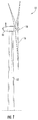
- FIG. 1 illustrates a perspective view of a horizontal axis wind turbine 10.
- the wind turbine 10 may be a vertical-axis wind turbine.
- the wind turbine 10 includes a tower 12, a nacelle 14 mounted on the tower 12, and a rotor hub 18 that is coupled to the nacelle 14.
- the tower 12 may be fabricated from tubular steel or other suitable material.
- the rotor hub 18 includes rotor blades 16 coupled to and extending radially outward from the hub 18. As shown, the rotor hub 18 includes three rotor blades 16. However, in an alternative embodiment, the rotor hub 18 may include more or less than three rotor blades 16.
- the rotor blades 16 may generally have any suitable length that enables the wind turbine 10 to function according to design criteria.
- the rotor blades 16 may have a length ranging from about 15 meters (m) to about 90 m.
- other non-limiting examples of blade lengths may include less than 15 m, from about 20 m, from about 30 m, or a length that is greater than 90 m.
- the rotor blades 16 rotate the rotor hub 18 to enable kinetic energy to be transferred from the wind into usable mechanical energy, and subsequently, electrical energy.
- the hub 18 may be rotatably coupled to an electric generator (not illustrated) positioned within the nacelle 14 for production of electrical energy.
- FIG. 2 a cross-sectional view of one embodiment of a wind turbine rotor blade 16 having a lightning protection system 50 configured therein is provided.
- the rotor blade 16 includes a blade root 30, a blade tip 32, a pressure side 34, and a suction side 36.
- the pressure side 34 and suction side 36 extend between the blade root 30 and the blade tip 32 and define an internal cavity 38 for the blade 16.
- the rotor blade 16 may also include one or more longitudinally extending structural components configured to provide increased stiffness, buckling resistance and/or strength to the rotor blade 16.
- the rotor blade 16 may include a pair of longitudinally extending spar caps 40, 42 configured to be engaged against the opposing inner surfaces of the pressure and suction sides 34, 36 of the rotor blade 16, respectively. Additionally, one or more shear webs (not shown) may be disposed between the spar caps 40, 42 so as to form a beam-like configuration.
- the spar caps 40, 42 may generally be designed to control the bending stresses and/or other loads acting on the rotor blade 16 in a generally span-wise direction (a direction parallel to the span 43 of the rotor blade 16) during operation of a wind turbine 10.
- the spar caps 40, 42 may be formed from any suitable laminate composite material, including but not limited to laminate composites reinforced with carbon, mixtures of carbon, fiberglass, mixtures of fiberglass, mixtures of carbon and fiberglass and any other suitable reinforcement material and mixtures thereof.
- the lightning protection system 50 of the wind turbine 10 may include a lightning conductive circuit 52 configured with one or more of the rotor blades 16.
- the lightning protection system 50 includes three lightning protection circuits 52, or one circuit per rotor blade 22.
- the lightning protection system 50 may include more than three or less than three circuits 52. More specifically, the number of circuits 52 in the lightning protection system 50 may correspond to the number of rotor blades 22 of the turbine 10. It should also be understood that any portion of the lightning protection system 50 may include existing blade structures within the circuit 52, such as the carbon spar caps, trailing serrations, leading edge protectors, fairings, and so forth.
- each lightning conductive circuit 52 includes at least one electrical conductor 54 configured with at least one semiconductor 44.
- the semiconductor(s) 44 is located within the internal cavity 38 at or near the blade root 30 of the rotor blade 16.
- the electrical conductor 54 is configured to electrically couple the blade tip 32 of the rotor blade 16 to ground, e.g. via a ground conductor 47.
- the electrical conductor 54 may include a cable wire having one or more conductive members or wires 56 extending therefrom so as to electrically couple the pressure and suction spar caps 40, 42 near the blade tip 32 to the ground conductor 47. For example, as shown in FIG.
- the electrical conductor 54 includes four conductive members 56 extending from a distal end of the electrical conductor 54 such that the conductor 54 contacts each of the spar caps 40, 42 at two connection points 58, which will be described in more detail below.
- the electrical conductor 54 may include more than four or less than four conductive members 56.
- the electrical conductor 54 extends from the blade tip 32 to the blade root 30 and electrically couples one or more semiconductors 44 between the pressure and suction side spar caps 40, 42 and the ground conductor 47. More specifically, as shown, the lightning conductive circuit 52 may include at least two semiconductors 44 at or near the blade root 30. Thus, a first semiconductor 44 may be electrically coupled to the pressure side spar cap 40 and the ground conductor 47 via one or more of the conductive members 56 and a second semiconductor 44 may be electrically coupled to the suction side spar cap 42 and the ground conductor 47 via one or more of the conductive members 56.
- the conductive members 56 are configured to electrically couple the semiconductor(s) 44 to either or both of the pressure or suction side spar caps 40, 42 at one or more connection points 58. Accordingly, the semiconductors 44 are intentionally located electrically at the blade root 30 between the spar caps 40, 42 and the ground conductor 47 to provide adequate lightning protection for the wind turbine 10.
- the electrical conductor 54 may be electrically coupled to the either or both of the pressure or suction sides 34, 36 of the rotor blade 16 via one or more electrical connections 62, 67 at the connection points 58.
- the electrical connections 62 may include conventional connections having one or more through-bolts 64 configured completely through either or both of the pressure or suction side spar caps 40, 42 of the rotor blade 22.
- the electrical connections 62 may also include one or more conductive plates 66 configured on one or more sides of the spar caps 40, 42 with the through-bolts 64 extending therethrough to provide a solid electrical connection.
- the electrical connections 67 may include one or more fasteners 68 configured partially through either or both of the pressure or suction side spar caps 40, 42 of the rotor blade 22.
- Such electrical connections 67 may also include at least one conductive plate 70 similar to the plates 66 of FIG. 4 .
- the electrical connection 67 only requires one plate 70 as the fasteners 68 do not extend all the way through the spar caps 40, 42.
- the connections 67 of FIG. 5 may be weaker than the connections 62 of FIG. 4 , such connections 67 still provide sufficient management of the current and voltage within the rotor blade 22 caused by lightning strikes due to the configuration of the lightning conductive circuit 52.
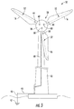
- each of the electrical conductors 54 of each lightning conductive circuit 52 may also include at least one terminal end 60 that extends through the blade root 30 of each rotor blade 16 and are individually connected to a grounding system within the rotor hub 18. More specifically, the lightning conductive circuit 50 may have a gauge suitable for defining a conductive leg for transmitting a lightning strike occurring on the blade 16 to ground via connection of the terminal end 60 to the wind turbine's ground system.
- the ground system may be variously configured, as is well known in the art.
- the ground system may include any conductive path defined by the wind turbine's machinery or support structure, including blade bearings, machinery bed plates, tower structure, and the like, that defines any suitable ground conductive path 48 from the blades 16, through the tower 12, to a ground rod 46 via a ground cable 45, or other suitable electrical ground path, to the ground 47.
- any suitable ground conductive path 48 from the blades 16, through the tower 12, to a ground rod 46 via a ground cable 45, or other suitable electrical ground path, to the ground 47.
- the semiconductor(s) 44 as described herein may be any suitable semiconductor now known or later developed in the art that provides adequate management of both current and voltage within the rotor blade 22 caused by a lightning strike.
- the semiconductor(s) of the present disclosure may have a tight voltage-current curve such that as voltage increases, current remains saturated (i.e. current is mitigated).
- the semiconductor(s) 44 of the present disclosure prevent arcing caused by lightning strikes.
- the semiconductor(s) 44 as described herein may include at least one of a varistor, a spark gap, a diode, or similar.
- the semiconductor(s) 44 may include a metal oxide varistor (MOV).
- MOV metal oxide varistor
- a MOV generally refers to a varistor with and electrical resistivity that varies with the applied voltage.
- a typically MOV includes a ceramic mass of zinc oxide grains configured in a matrix of other metal oxides and sandwiched between two metal plates (i.e. electrodes). The boundary between each grain and its neighbor forms a diode junction, which allows current to flow in only one direction.
- a typical MOV has a high resistance at low voltages and a low resistance at high voltages.
Landscapes
- Engineering & Computer Science (AREA)
- Life Sciences & Earth Sciences (AREA)
- Sustainable Development (AREA)
- Sustainable Energy (AREA)
- Chemical & Material Sciences (AREA)
- Combustion & Propulsion (AREA)
- Mechanical Engineering (AREA)
- General Engineering & Computer Science (AREA)
- Wind Motors (AREA)
- Elimination Of Static Electricity (AREA)
Abstract
Description
- The present subject matter relates generally to wind turbines, and more particularly to wind turbine rotor blades having a lightning protection system configured therewith.
- Wind power is considered one of the cleanest, most environmentally friendly energy sources presently available, and wind turbines have gained increased attention in this regard. A modem wind turbine typically includes a tower, a generator, a gearbox, a nacelle, and a rotor. The rotor typically includes a rotatable hub having one or more rotor blades attached thereto. A pitch bearing is typically configured operably between the hub and a blade root of the rotor blade to allow for rotation about a pitch axis. The rotor blades capture kinetic energy of wind using known airfoil principles. The rotor blades transmit the kinetic energy in the form of rotational energy so as to turn a shaft coupling the rotor blades to a gearbox, or if a gearbox is not used, directly to the generator. The generator then converts the mechanical energy to electrical energy that may be deployed to a utility grid.
- Large commercial wind turbines are prone to lightning strikes that can damage the rotor blades, particularly at the blade root. In this regard, it is a common practice to provide the turbine blades with lightning receptors spaced along the longitudinal length of the blade so as to capture and conduct the lightning strikes to ground. The conventional configuration of these receptors, however, results in difficult, expensive, and time-consuming maintenance and diagnostic procedures that typically requires a crane to externally access each receptor. The conventional configuration does not offer a means to verify the continuity of the receptors within a blade without accessing and testing each receptor individually. In addition, the effectiveness of the receptors depends on the integrity and reliability of a single conductive path along the blade. Failure (i.e., a break) of this path renders any upstream receptors essentially useless.
- Efforts have been made to devise alternative lightning protection systems for wind turbine blades. For example,
U.S. Patent Publication No. 2009/0129927 describes a system that avoids blade mounted receptors altogether by mounting radially extending lightning receptors to the rotor hub, with the receptors extending between the blades. This configuration, however, may result in increased weight, drag, and noise, and an overall decrease in the capability of the turbine. - Accordingly, the industry would benefit from an improved lightning protection system that addresses the aforementioned issues. Particularly, a lightning protection system for a wind turbine that prevents damage to the blade root would be advantageous.
- Various aspects and advantages of the invention will be set forth in part in the following description, or may be clear from the description, or may be learned through practice of the invention.
- In one aspect, the present disclosure is directed to a wind turbine rotor blade. The rotor blade includes a blade root, a blade tip, and a pressure side and a suction side extending between the blade tip and the blade root. Further, the pressure and suction sides define an internal cavity. The rotor blade also includes a lightning conductive circuit having at least one electrical conductor and at least one semiconductor located within the internal cavity at the blade root. Further, the electrical conductor electrically couples the blade tip to a ground conductor. In addition, the electrical conductor electrically couples the semiconductor between one or more spar caps located on either or both of the pressure or suction sides and the ground conductor.
- In one embodiment, the semiconductor may include any one of or a combination of the following: a varistor, a spark gap, a diode, or similar. More specifically, in certain embodiments, the varistor may be a metal oxide varistor (MOV). In addition, in particularly embodiments, the electrical conductor may include a cable wire.
- In further embodiments, the electrical conductor may include a plurality of conductive members electrically coupling the one or more spar caps located on either or both of the pressure or suction sides to the ground conductor. In particular embodiments, the conductive members may also be cable wires branching off from the electrical conductor. Thus, in certain embodiments, the conductive members are configured to electrically couple the blade tip to a pressure side spar cap and a suction side spar cap and to the ground conductor.
- In a specific embodiment, for example, the lightning conductive circuit includes at least two semiconductors, wherein one of the semiconductors is electrically coupled to the pressure side spar cap and the ground conductor via one or more of the conductive members, and wherein another one of the semiconductor is electrically coupled to the suction side spar cap and the ground conductor via one or more of the conductive members.
- In additional embodiments, the electrical conductor may be electrically coupled to the either or both of the pressure or suction side spar caps of the rotor blade via one or more electrical connections. More specifically, the electrical connections may include one or more fasteners configured partially through either or both of the pressure or suction side spar caps of the rotor blade. Alternatively, the electrical connections may include one or more through-bolts configured completely through either or both of the pressure or suction side spar caps of the rotor blade. In further embodiments, the electrical conductor may also include at least one terminal end that extends through the blade root to the ground conductor.
- In another aspect, the present disclosure is directed to a lightning protection system for a wind turbine rotor blade. The lightning protection system includes a lightning conductive circuit having at least one electrical conductor and at least one semiconductor. The semiconductor is configured for placement at or near a blade root of the rotor blade. Further, the electrical conductor is configured to electrically couple a blade tip of the rotor blade to a ground conductor. In addition, the electrical conductor is configured to electrically couple the semiconductor between one or more spar caps located on either or both of the pressure or suction sides at the blade root and the ground conductor. It should be understood that the lightning protection system may be further configured with any of the additional features as described herein.
- In yet another aspect, the present disclosure is directed to a wind turbine. The wind turbine includes a tower, a nacelle mounted atop the tower, and a rotor hub having a plurality of rotor blades mounted thereto. Each of the rotor blades includes a blade root, a blade tip, and a pressure side and a suction side extending between the blade tip and the blade root. Further, the pressure and suction sides define an internal cavity. In addition, at least one of the rotor blades further includes a lightning conductive circuit having at least one electrical conductor and at least one semiconductor located within the internal cavity of the rotor blade at the blade root. Further, the electrical conductor electrically couples the blade tip to a ground conductor. In addition, the electrical conductor electrically couples the semiconductor between one or more spar caps located on either or both of the pressure or suction sides and the ground conductor.
- Various features, aspects and advantages of the present invention will become better understood with reference to the following description and appended claims. The accompanying drawings, which are incorporated in and constitute a part of this specification, illustrate embodiments of the invention and, together with the description, serve to explain the principles of the invention. In the drawings:
-
FIG. 1 illustrates a perspective view of a conventional wind turbine; -
FIG. 2 illustrates a cross-sectional view of one embodiment of a rotor blade having a lightning protection system installed within an internal cavity of the blade according to the present disclosure; -
FIG. 3 illustrates a front view of one embodiment of a wind turbine having a lightning protection system installed thereon according to the present disclosure; -
FIG. 4 illustrates a cross-sectional view of one embodiment of a spar cap of a wind turbine rotor blade, particularly illustrating a plurality of through-bolt electrical connections of a lightning protection system configured through the spar cap according to conventional construction; and -
FIG. 5 illustrates a cross-sectional view of one embodiment of a spar cap of a wind turbine rotor blade, particularly illustrating an electrical connection of a lightning protection system to the spar cap according to the present disclosure. - Reference now will be made in detail to embodiments of the invention, one or more examples of which are illustrated in the drawings. Each example is provided by way of explanation of the invention, not limitation of the invention. In fact, it will be apparent to those skilled in the art that various modifications and variations can be made in the present invention without departing from the scope or spirit of the invention. For instance, features illustrated or described as part of one embodiment can be used with another embodiment to yield a still further embodiment. Thus, it is intended that the present invention covers such modifications and variations as come within the scope of the appended claims and their equivalents.
- Generally, the present disclosure is directed to a lightning protection system for a wind turbine rotor blade. The lightning protection system includes a lightning conductive circuit having at least one electrical conductor electrically coupled with at least one semiconductor. Further, the semiconductor is located within an internal cavity of the rotor blade at the blade root. The electrical conductor is configured to electrically couple the blade tip of the rotor blade to a ground conductor. Further, the electrical conductor is configured to electrically couple the semiconductor between one or more spar caps located on either or both of the pressure or suction sides and the ground conductor.
- Thus, the present disclosure provides many advantages not present in the prior art. For example, the lightning protection system of the present disclosure can be can be retrofitted to the wind turbine without lowering the blade. Further, the present disclosure is relatively inexpensive and easier to install in comparison to other retrofit solutions. Moreover, damaging transient over-voltage conditions and currents through the spar caps can be minimized and/or eliminated. In addition, through-bolt connections through the spar caps, which can weaken the structural integrity of the spar caps, is not required. Thus, the equipotential connections made between the carbon spar caps and the down conductor can be reduced. Even further, if the blade tip connection is lost and arcing current occurs (thereby damaging the blade), the blade tip is easier to repair than the entire rotor blade.
- Referring to the drawings,
FIG. 1 illustrates a perspective view of a horizontalaxis wind turbine 10. It should be appreciated that thewind turbine 10 may be a vertical-axis wind turbine. In the illustrated embodiment, thewind turbine 10 includes atower 12, anacelle 14 mounted on thetower 12, and arotor hub 18 that is coupled to thenacelle 14. Thetower 12 may be fabricated from tubular steel or other suitable material. Therotor hub 18 includesrotor blades 16 coupled to and extending radially outward from thehub 18. As shown, therotor hub 18 includes threerotor blades 16. However, in an alternative embodiment, therotor hub 18 may include more or less than threerotor blades 16. - The
rotor blades 16 may generally have any suitable length that enables thewind turbine 10 to function according to design criteria. For example, therotor blades 16 may have a length ranging from about 15 meters (m) to about 90 m. However, other non-limiting examples of blade lengths may include less than 15 m, from about 20 m, from about 30 m, or a length that is greater than 90 m. Thus, therotor blades 16 rotate therotor hub 18 to enable kinetic energy to be transferred from the wind into usable mechanical energy, and subsequently, electrical energy. Specifically, thehub 18 may be rotatably coupled to an electric generator (not illustrated) positioned within thenacelle 14 for production of electrical energy. - Referring now to
FIG. 2 , a cross-sectional view of one embodiment of a windturbine rotor blade 16 having alightning protection system 50 configured therein is provided. As shown, therotor blade 16 includes ablade root 30, ablade tip 32, apressure side 34, and asuction side 36. Thepressure side 34 andsuction side 36 extend between theblade root 30 and theblade tip 32 and define aninternal cavity 38 for theblade 16. Therotor blade 16 may also include one or more longitudinally extending structural components configured to provide increased stiffness, buckling resistance and/or strength to therotor blade 16. For example, therotor blade 16 may include a pair of longitudinally extending spar caps 40, 42 configured to be engaged against the opposing inner surfaces of the pressure andsuction sides rotor blade 16, respectively. Additionally, one or more shear webs (not shown) may be disposed between the spar caps 40, 42 so as to form a beam-like configuration. The spar caps 40, 42 may generally be designed to control the bending stresses and/or other loads acting on therotor blade 16 in a generally span-wise direction (a direction parallel to thespan 43 of the rotor blade 16) during operation of awind turbine 10. - In several embodiments of the present subject matter, the spar caps 40, 42 may be formed from any suitable laminate composite material, including but not limited to laminate composites reinforced with carbon, mixtures of carbon, fiberglass, mixtures of fiberglass, mixtures of carbon and fiberglass and any other suitable reinforcement material and mixtures thereof.
- Referring generally to
FIGS. 2 and3 , thelightning protection system 50 of thewind turbine 10 may include a lightningconductive circuit 52 configured with one or more of therotor blades 16. For example, as shown, thelightning protection system 50 includes threelightning protection circuits 52, or one circuit per rotor blade 22. In additional embodiments, thelightning protection system 50 may include more than three or less than threecircuits 52. More specifically, the number ofcircuits 52 in thelightning protection system 50 may correspond to the number of rotor blades 22 of theturbine 10. It should also be understood that any portion of thelightning protection system 50 may include existing blade structures within thecircuit 52, such as the carbon spar caps, trailing serrations, leading edge protectors, fairings, and so forth. - As shown, each lightning
conductive circuit 52 includes at least oneelectrical conductor 54 configured with at least onesemiconductor 44. Further, the semiconductor(s) 44 is located within theinternal cavity 38 at or near theblade root 30 of therotor blade 16. Thus, theelectrical conductor 54 is configured to electrically couple theblade tip 32 of therotor blade 16 to ground, e.g. via aground conductor 47. More specifically, theelectrical conductor 54 may include a cable wire having one or more conductive members orwires 56 extending therefrom so as to electrically couple the pressure and suction spar caps 40, 42 near theblade tip 32 to theground conductor 47. For example, as shown inFIG. 2 , theelectrical conductor 54 includes fourconductive members 56 extending from a distal end of theelectrical conductor 54 such that theconductor 54 contacts each of the spar caps 40, 42 at two connection points 58, which will be described in more detail below. In further embodiments, theelectrical conductor 54 may include more than four or less than fourconductive members 56. - Referring particularly to
FIG. 2 , theelectrical conductor 54 extends from theblade tip 32 to theblade root 30 and electrically couples one ormore semiconductors 44 between the pressure and suction side spar caps 40, 42 and theground conductor 47. More specifically, as shown, the lightningconductive circuit 52 may include at least twosemiconductors 44 at or near theblade root 30. Thus, afirst semiconductor 44 may be electrically coupled to the pressure side sparcap 40 and theground conductor 47 via one or more of theconductive members 56 and asecond semiconductor 44 may be electrically coupled to the suction side sparcap 42 and theground conductor 47 via one or more of theconductive members 56. In addition, as shown, theconductive members 56 are configured to electrically couple the semiconductor(s) 44 to either or both of the pressure or suction side spar caps 40, 42 at one or more connection points 58. Accordingly, thesemiconductors 44 are intentionally located electrically at theblade root 30 between the spar caps 40, 42 and theground conductor 47 to provide adequate lightning protection for thewind turbine 10. - Referring now to
FIGS. 4 and 5 , theelectrical conductor 54 may be electrically coupled to the either or both of the pressure orsuction sides rotor blade 16 via one or moreelectrical connections FIG. 4 , theelectrical connections 62 may include conventional connections having one or more through-bolts 64 configured completely through either or both of the pressure or suction side spar caps 40, 42 of the rotor blade 22. More specifically, as shown, theelectrical connections 62 may also include one or moreconductive plates 66 configured on one or more sides of the spar caps 40, 42 with the through-bolts 64 extending therethrough to provide a solid electrical connection. As mentioned, however,such connections 62 may be time-consuming and expensive to install and may compromise the structural integrity of the rotor blade 22. As such, in an alternative embodiment, as shown inFIG. 5 , theelectrical connections 67 may include one ormore fasteners 68 configured partially through either or both of the pressure or suction side spar caps 40, 42 of the rotor blade 22. Suchelectrical connections 67 may also include at least oneconductive plate 70 similar to theplates 66 ofFIG. 4 . As shown inFIG. 5 , however, theelectrical connection 67 only requires oneplate 70 as thefasteners 68 do not extend all the way through the spar caps 40, 42. Though theconnections 67 ofFIG. 5 may be weaker than theconnections 62 ofFIG. 4 ,such connections 67 still provide sufficient management of the current and voltage within the rotor blade 22 caused by lightning strikes due to the configuration of the lightningconductive circuit 52. - Referring particularly to
FIG. 3 , each of theelectrical conductors 54 of each lightningconductive circuit 52 may also include at least oneterminal end 60 that extends through theblade root 30 of eachrotor blade 16 and are individually connected to a grounding system within therotor hub 18. More specifically, the lightningconductive circuit 50 may have a gauge suitable for defining a conductive leg for transmitting a lightning strike occurring on theblade 16 to ground via connection of theterminal end 60 to the wind turbine's ground system. The ground system may be variously configured, as is well known in the art. For example, the ground system may include any conductive path defined by the wind turbine's machinery or support structure, including blade bearings, machinery bed plates, tower structure, and the like, that defines any suitable groundconductive path 48 from theblades 16, through thetower 12, to aground rod 46 via aground cable 45, or other suitable electrical ground path, to theground 47. - The semiconductor(s) 44 as described herein may be any suitable semiconductor now known or later developed in the art that provides adequate management of both current and voltage within the rotor blade 22 caused by a lightning strike. For example, the semiconductor(s) of the present disclosure may have a tight voltage-current curve such that as voltage increases, current remains saturated (i.e. current is mitigated). Thus, the semiconductor(s) 44 of the present disclosure prevent arcing caused by lightning strikes. More specifically, in certain embodiments, the semiconductor(s) 44 as described herein may include at least one of a varistor, a spark gap, a diode, or similar. More specifically, in certain embodiments, the semiconductor(s) 44 may include a metal oxide varistor (MOV). As used herein, a MOV generally refers to a varistor with and electrical resistivity that varies with the applied voltage. Further, a typically MOV includes a ceramic mass of zinc oxide grains configured in a matrix of other metal oxides and sandwiched between two metal plates (i.e. electrodes). The boundary between each grain and its neighbor forms a diode junction, which allows current to flow in only one direction. Thus, a typical MOV has a high resistance at low voltages and a low resistance at high voltages.
- This written description uses examples to disclose the invention, including the preferred mode, and also to enable any person skilled in the art to practice the invention, including making and using any devices or systems and performing any incorporated methods. The patentable scope of the invention is defined by the claims, and may include other examples that occur to those skilled in the art. Such other examples are intended to be within the scope of the claims if they include structural elements that do not differ from the literal language of the claims, or if they include equivalent structural elements with insubstantial differences from the literal languages of the claims.
- Various aspects and embodiments of the present invention are defined by the following numbered clauses:
- 1. A wind turbine rotor blade, comprising:
- a blade root, a blade tip, and a pressure side and a suction side extending between the blade tip and the blade root, the pressure and suction sides defining an internal cavity; and,
- a lightning conductive circuit comprising at least one electrical conductor and at least one semiconductor located within the internal cavity at the blade root,
- wherein the electrical conductor electrically couples the blade tip to a ground conductor, and wherein the electrical conductor electrically couples the semiconductor between one or more spar caps located on either or both of the pressure or suction sides and the ground conductor.
- 2. The wind turbine blade of clause 1, wherein the at least one semiconductor comprises at least one of a varistor, a spark gap, or a diode.
- 3. The wind turbine blade of any preceding clause, wherein the varistor comprises a metal oxide varistor (MOV).
- 4. The wind turbine blade of any preceding clause, wherein the at least one electrical conductor comprises a cable wire.
- 5. The wind turbine blade of any preceding clause, wherein the electrical conductor further comprises a plurality of conductive members electrically coupling the one or more spar caps located on either or both of the pressure or suction sides to the ground conductor.
- 6. The wind turbine blade of any preceding clause, wherein the plurality of conductive members comprises cable wires extending from the electrical conductor.
- 7. The wind turbine blade of any preceding clause, wherein the plurality of conductive members electrically couple the blade tip to a pressure side spar cap and a suction side spar cap and to the ground conductor.
- 8. The wind turbine blade of any preceding clause, wherein the lightning conductive circuit further comprises at least two semiconductors, wherein one of the semiconductors is electrically coupled to the pressure side spar cap and the ground conductor via one or more of the conductive members, and wherein another one of the semiconductors is electrically coupled to the suction side spar cap and the ground conductor via one or more of the conductive members.
- 9. The wind turbine blade of any preceding clause, wherein the electrical conductor is electrically coupled to the either or both of the pressure or suction side spar caps of the rotor blade via one or more electrical connections, wherein the electrical connections comprise one or more fasteners configured partially through either or both of the pressure or suction side spar caps of the rotor blade.
- 10. The wind turbine blade of any preceding clause, wherein the electrical conductor further comprises at least one terminal end that extends through the blade root to the ground conductor.
- 11. A lightning protection system for a wind turbine rotor blade, the lightning protection system comprising:
- a lightning conductive circuit comprising at least one electrical conductor and at least one semiconductor, the semiconductor configured for placement at a blade root of the rotor blade,
- wherein the electrical conductor is configured to electrically couple a blade tip of the rotor blade to a ground conductor, and wherein the electrical conductor is configured to electrically couple the semiconductor between one or more spar caps located on either or both of the pressure or suction sides at the blade root and the ground conductor.
- 12. The lightning protection system of any preceding clause, wherein the at least one semiconductor comprises at least one of a varistor, a spark gap, or a diode.
- 13. The lightning protection system of any preceding clause, wherein the varistor comprises a metal oxide varistor (MOV).
- 14. The lightning protection system of any preceding clause, wherein the at least one electrical conductor comprises a cable wire.
- 15. The lightning protection system of any preceding clause, wherein the electrical conductor further comprises a plurality of conductive members configured to electrically couple the one or more spar caps located on either or both of the pressure or suction sides to the ground conductor.
- 16. The lightning protection system of any preceding clause, wherein the plurality of conductive members comprises cable wires extending from the electrical conductor.
- 17. The lightning protection system of any preceding clause, wherein the plurality of conductive members are configured to electrically couple the blade tip to a pressure side spar cap and a suction side spar cap and to the ground conductor.
- 18. The lightning protection system of any preceding clause, wherein the lightning conductive circuit further comprises at least two semiconductors, wherein at least one of the plurality of conductive members is configured to electrically couple one of the semiconductors to the pressure side spar cap and the ground conductor, and wherein at least another one of the conductive members is configured to electrically couple another one of the semiconductors to the suction side spar cap and the ground conductor.
- 19. The lightning protection system of any preceding clause, wherein the electrical conductor further comprises at least one terminal end that extends through the blade root to the ground conductor.
- 20. A wind turbine, comprising:
- a tower;
- a nacelle mounted atop the tower;
- a rotor hub comprising a plurality of rotor blades mounted thereto, each of the rotor blades comprising a blade root, a blade tip, and a pressure side and a suction side extending between the blade tip and the blade root, the pressure and suction sides defining an internal cavity;
- at least one of the rotor blades further comprising:
- a lightning conductive circuit comprising at least one electrical conductor and at least one semiconductor located within the internal cavity at the blade root,
- wherein the electrical conductor electrically couples the blade tip to a ground conductor, and wherein the electrical conductor electrically couples the semiconductor between one or more spar caps located on either or both of the pressure or suction sides and the ground conductor.
Claims (15)
- A wind turbine rotor blade (16), comprising:a blade root (30), a blade tip (32), and a pressure side and a suction side extending between the blade tip (32) and the blade root (30), the pressure and suction sides defining an internal cavity (38); and,a lightning conductive circuit (52) comprising at least one electrical conductor (54) and at least one semiconductor (44) located within the internal cavity (38) at the blade root (30),wherein the electrical conductor (54) electrically couples the blade tip (32) to a ground conductor (47), and wherein the electrical conductor (54) electrically couples the semiconductor (44) between one or more spar caps located on either or both of the pressure or suction sides and the ground conductor (47).
- The wind turbine blade (16) of claim 1, wherein the at least one semiconductor (44) comprises at least one of a varistor, a spark gap, or a diode.
- The wind turbine blade of claim 2, wherein the varistor comprises a metal oxide varistor (MOV).
- The wind turbine blade (16) of any preceding claim, wherein the at least one electrical conductor (54) comprises a cable wire.
- The wind turbine blade (16) of any preceding claim, wherein the electrical conductor (54) further comprises a plurality of conductive members (56) electrically coupling the one or more spar caps (40, 42) located on either or both of the pressure or suction sides (34, 36) to the ground conductor (47).
- The wind turbine blade (16) of any preceding claim, wherein the plurality of conductive members (56) comprises cable wires extending from the electrical conductor (54).
- The wind turbine blade (16) of any preceding claim, wherein the plurality of conductive members (56) electrically couple the blade tip (32) to a pressure side spar cap (40) and a suction side spar cap (42) and to the ground conductor (47).
- The wind turbine blade (16) of any preceding claim, wherein the lightning conductive circuit (52) further comprises at least two semiconductors (44), wherein one of the semiconductor (44)s is electrically coupled to the pressure side spar cap (40) and the ground conductor (47) via one or more of the conductive members (56), and wherein another one of the semiconductors (44) is electrically coupled to the suction side spar cap (42) and the ground conductor (47) via one or more of the conductive members (56).
- The wind turbine blade (16) of any preceding claim, wherein the electrical conductor (54) is electrically coupled to the either or both of the pressure or suction side spar caps (40, 42) of the rotor blade (16) via one or more connection points (58), wherein the connection points (58) comprise one or more fasteners (68) configured partially through either or both of the pressure or suction side spar caps (40, 42) of the rotor blade (16).
- A lightning protection system (50) for a wind turbine rotor blade, the lightning protection system (50) comprising:a lightning conductive circuit (52) comprising at least one electrical conductor (54) and at least one semiconductor (44), the semiconductor (44) configured for placement at a blade root (30) of the rotor blade (16),wherein the electrical conductor (54) is configured to electrically couple a blade tip (32) of the rotor blade (16) to a ground conductor (47), and wherein the electrical conductor (54) is configured to electrically couple the semiconductor (44) between one or more spar caps (40, 42) located on either or both of the pressure or suction sides (34, 36) at the blade root (30) and the ground conductor (47).
- The lightning protection system (50) of claim 10, wherein the at least one semiconductor (44) comprises at least one of a varistor, a spark gap, or a diode, wherein the varistor comprises a metal oxide varistor (MOV).
- The lightning protection system (50) of claim 10 or claim 11, wherein the at least one electrical conductor (54) comprises a cable wire.
- The lightning protection system (50) of any of claims 10 to 12, wherein the electrical conductor (54) further comprises a plurality of conductive members (56) configured to electrically couple the one or more spar caps (40, 42) located on either or both of the pressure or suction sides (34, 36) to the ground conductor (47), wherein the plurality of conductive members (56) comprises cable wires extending from the electrical conductor (54), wherein the plurality of conductive members (56) are configured to electrically couple the blade tip (32) to a pressure side spar cap (40) and a suction side spar cap (42) and to the ground conductor (47).
- The lightning protection system (50) of any of claims 10 to 13, wherein the lightning conductive circuit (52) further comprises at least two semiconductors (44), wherein at least one of the plurality of conductive members (56) is configured to electrically couple one of the semiconductors (44) to the pressure side spar cap (40) and the ground conductor (47), and wherein at least another one of the conductive members (56) is configured to electrically couple another one of the semiconductors (44) to the suction side spar cap (42) and the ground conductor (47).
- A wind turbine (10), comprising:a tower (12);a nacelle (14) mounted atop the tower (12);a rotor hub (18) comprising a plurality of rotor blades (16) mounted thereto, each of the rotor blades (16) comprising a blade root (30), a blade tip (32), and a pressure side (34) and a suction side (36) extending between the blade tip (32) and the blade root (30), the pressure and suction sides (34, 36) defining an internal cavity (38);at least one of the rotor blades (16) further comprising:a lightning conductive circuit (52) comprising at least one electrical conductor (54) and at least one semiconductor (44) located within the internal cavity (38) at the blade root (30),wherein the electrical conductor (54) electrically couples the blade tip (32) to a ground conductor (47), and wherein the electrical conductor (54) electrically couples the semiconductor (44) between one or more spar caps (40, 42) located on either or both of the pressure or suction sides (34, 36) and the ground conductor (47).
Applications Claiming Priority (1)
| Application Number | Priority Date | Filing Date | Title |
|---|---|---|---|
| US14/710,632 US9719495B2 (en) | 2015-05-13 | 2015-05-13 | Lightning protection system for wind turbine rotor blades |
Publications (2)
| Publication Number | Publication Date |
|---|---|
| EP3093487A1 true EP3093487A1 (en) | 2016-11-16 |
| EP3093487B1 EP3093487B1 (en) | 2018-03-21 |
Family
ID=55913541
Family Applications (1)
| Application Number | Title | Priority Date | Filing Date |
|---|---|---|---|
| EP16168474.1A Active EP3093487B1 (en) | 2015-05-13 | 2016-05-05 | Lightning protection system for wind turbine rotor blades |
Country Status (3)
| Country | Link |
|---|---|
| US (1) | US9719495B2 (en) |
| EP (1) | EP3093487B1 (en) |
| DK (1) | DK3093487T3 (en) |
Cited By (1)
| Publication number | Priority date | Publication date | Assignee | Title |
|---|---|---|---|---|
| US11225947B2 (en) | 2016-06-20 | 2022-01-18 | Vestas Wind Systems A/S | Method of securing cables to a wind turbine blade |
Families Citing this family (6)
| Publication number | Priority date | Publication date | Assignee | Title |
|---|---|---|---|---|
| MX2020011146A (en) * | 2018-04-27 | 2021-04-19 | Gen Electric | Tip extensions for wind turbine rotor blades and methods of installing same. |
| EP3857063B1 (en) * | 2018-09-24 | 2025-06-18 | Polytech A/S | Down conductor connection system, wind turbine lightning protection system, and method for arranging a down conductor connection system |
| CN115516202A (en) * | 2020-05-14 | 2022-12-23 | 西门子歌美飒可再生能源公司 | Wind turbine blades and wind turbines |
| FI130757B1 (en) * | 2021-01-12 | 2024-02-27 | Wicetec Oy | A wind turbine blade comprising a potential control arrangement |
| JP7061327B1 (en) | 2021-03-19 | 2022-04-28 | 国立大学法人東海国立大学機構 | Wind power generation equipment and its rotary blades and control method for wind power generation equipment |
| EP4166780A1 (en) * | 2021-10-13 | 2023-04-19 | Siemens Gamesa Renewable Energy A/S | A rotor blade lightning protection system with spark-gaps for equipotential bonds |
Citations (4)
| Publication number | Priority date | Publication date | Assignee | Title |
|---|---|---|---|---|
| WO2000079128A1 (en) * | 1999-06-21 | 2000-12-28 | Lm Glasfiber A/S | Wind turbine blade with a system for deicing and lightning protection |
| US20090129927A1 (en) | 2005-10-06 | 2009-05-21 | Peter Grabau | Wind Power Plant with Lightning Protection Arrangement |
| EP2336560A1 (en) * | 2009-12-15 | 2011-06-22 | Vestas Wind Systems A/S | Lightning current transfer assembly for a wind turbine |
| DE102011014537B3 (en) * | 2011-03-18 | 2012-05-31 | Nordex Energy Gmbh | Wind turbine with a rotor blade and a lightning rod |
Family Cites Families (20)
| Publication number | Priority date | Publication date | Assignee | Title |
|---|---|---|---|---|
| DK173460B2 (en) | 1998-09-09 | 2004-08-30 | Lm Glasfiber As | Windmill wing with lightning conductor |
| ES2317896T3 (en) | 2000-04-10 | 2009-05-01 | Jomitek Aps | SYSTEM OF PROTECTION AGAINST RAYS, FOR EXAMPLE, FOR AN AEROGENERATOR, AEROGENERATOR SHOVEL THAT PRESENTS A SYSTEM OF PROTECTION AGAINST RAYS, PROCEDURE OF CREATION OF A SYSTEM OF PROTECTION AGAINST RAYS AND ITS USE. |
| DK177270B1 (en) | 2002-11-12 | 2012-09-10 | Lm Wind Power As | Lightning protection of pitch-regulated wind turbine wings |
| DK200300882A (en) | 2003-06-12 | 2004-12-13 | Lm Glasfiber As | Lightning detection, including in wind power plants |
| DK176298B1 (en) | 2003-09-15 | 2007-06-18 | Lm Glasfiber As | Method of lightning protection of a blade for a wind power plant, a lightning protection wing and a wind power plant with such a blade |
| EP1826402B1 (en) * | 2004-11-11 | 2016-08-24 | Gamesa Innovation & Technology, S.L. | Lightning conductor system for wind generator blades comprising carbon fibre laminates |
| DK1754887T3 (en) | 2005-08-17 | 2016-01-11 | Gen Electric | A device for detecting lynnedslagsskade on a wind turbine blade |
| US7348683B2 (en) * | 2005-11-17 | 2008-03-25 | General Electric Company | Rotor for a wind energy turbine |
| US7468505B2 (en) | 2006-07-21 | 2008-12-23 | General Electric Company | Fiber optic current sensor system and method for detecting lightning |
| US8182227B2 (en) | 2008-02-01 | 2012-05-22 | General Electric Company | Wind turbine blade with lightning receptor |
| US8777579B2 (en) | 2008-06-20 | 2014-07-15 | Vestas Wind Systems A/S | Method of manufacturing a spar for a wind turbine from elements comprising different materials |
| US8137074B2 (en) | 2008-08-21 | 2012-03-20 | General Electric Company | Wind turbine lightning protection system |
| CN201810500U (en) | 2010-09-20 | 2011-04-27 | 江苏环球龙圣环境科技发展有限公司 | Cabin cover of wind driven generator |
| JP5535886B2 (en) * | 2010-11-30 | 2014-07-02 | 三菱重工業株式会社 | Lightning strike detection device, wind turbine rotor and wind power generator equipped with the same |
| US20110142671A1 (en) * | 2010-12-01 | 2011-06-16 | General Electric Company | Wind turbine rotor blades with enhanced lightning protection system |
| US8096765B2 (en) | 2010-12-01 | 2012-01-17 | General Electric Company | Wind turbine rotor blades with enhanced lightning protection system |
| EP2520796B1 (en) * | 2011-05-03 | 2015-08-12 | Siemens Aktiengesellschaft | Lightning protection system for a wind turbine and method for protecting components of a wind turbine against lightning strikes |
| US8258773B2 (en) * | 2011-06-09 | 2012-09-04 | General Electric Company | System for detecting lightning strikes on wind turbine rotor blades |
| DE102011105228B3 (en) | 2011-06-10 | 2012-09-20 | Nordex Energy Gmbh | Wind turbine component with an electrical cable embedded in a laminate |
| US10316827B2 (en) * | 2014-11-11 | 2019-06-11 | General Electric Company | Conduit assembly for a lightning protection cable of a wind turbine rotor blade |
-
2015
- 2015-05-13 US US14/710,632 patent/US9719495B2/en active Active
-
2016
- 2016-05-05 EP EP16168474.1A patent/EP3093487B1/en active Active
- 2016-05-05 DK DK16168474.1T patent/DK3093487T3/en active
Patent Citations (4)
| Publication number | Priority date | Publication date | Assignee | Title |
|---|---|---|---|---|
| WO2000079128A1 (en) * | 1999-06-21 | 2000-12-28 | Lm Glasfiber A/S | Wind turbine blade with a system for deicing and lightning protection |
| US20090129927A1 (en) | 2005-10-06 | 2009-05-21 | Peter Grabau | Wind Power Plant with Lightning Protection Arrangement |
| EP2336560A1 (en) * | 2009-12-15 | 2011-06-22 | Vestas Wind Systems A/S | Lightning current transfer assembly for a wind turbine |
| DE102011014537B3 (en) * | 2011-03-18 | 2012-05-31 | Nordex Energy Gmbh | Wind turbine with a rotor blade and a lightning rod |
Cited By (1)
| Publication number | Priority date | Publication date | Assignee | Title |
|---|---|---|---|---|
| US11225947B2 (en) | 2016-06-20 | 2022-01-18 | Vestas Wind Systems A/S | Method of securing cables to a wind turbine blade |
Also Published As
| Publication number | Publication date |
|---|---|
| US9719495B2 (en) | 2017-08-01 |
| EP3093487B1 (en) | 2018-03-21 |
| US20160333861A1 (en) | 2016-11-17 |
| DK3093487T3 (en) | 2018-06-06 |
Similar Documents
| Publication | Publication Date | Title |
|---|---|---|
| EP3093487B1 (en) | Lightning protection system for wind turbine rotor blades | |
| US8182227B2 (en) | Wind turbine blade with lightning receptor | |
| US9989036B2 (en) | Wind turbine blade lightning bypass system | |
| CN108700041B (en) | Wind turbine blade and potential equalising system | |
| US11248587B2 (en) | Wind turbine blade and a wind turbine | |
| US8096765B2 (en) | Wind turbine rotor blades with enhanced lightning protection system | |
| JP4580169B2 (en) | Split blade for windmill and lightning protection device for windmill | |
| US10648456B2 (en) | Organic conductive elements for deicing and lightning protection of a wind turbine rotor blade | |
| EP2423499A1 (en) | Lightning protection for wind turbines | |
| CN108266335B (en) | A blade lightning protection device for wind power generation equipment | |
| US11105314B2 (en) | Wind turbine blade and a wind turbine | |
| EP2461029A2 (en) | Wind Turbine Rotor Blades With Enhanced Lightning Protection System | |
| US11795920B2 (en) | Lightning protection for a wind turbine blade | |
| CN105386943A (en) | Wind driven generator blade point lightning protection device | |
| WO2021180389A1 (en) | Wind turbine blade assembly and method for manufacturing | |
| CN120265878A (en) | Lightning protection systems for wind turbine rotor blades | |
| CN101321948B (en) | Wind power plant with lightning protection arrangement | |
| US12215673B2 (en) | System comprising a structure being prone to lightning strikes and icing, a method for operating the system and a wind turbine comprising the system | |
| CN207715307U (en) | A kind of wind generator set blade Lightning Transformation device | |
| EP4426930B1 (en) | Wind turbine blade and wind turbine | |
| WO2025093095A1 (en) | Wind turbine ice protection |
Legal Events
| Date | Code | Title | Description |
|---|---|---|---|
| PUAI | Public reference made under article 153(3) epc to a published international application that has entered the european phase |
Free format text: ORIGINAL CODE: 0009012 |
|
| AK | Designated contracting states |
Kind code of ref document: A1 Designated state(s): AL AT BE BG CH CY CZ DE DK EE ES FI FR GB GR HR HU IE IS IT LI LT LU LV MC MK MT NL NO PL PT RO RS SE SI SK SM TR |
|
| AX | Request for extension of the european patent |
Extension state: BA ME |
|
| 17P | Request for examination filed |
Effective date: 20170516 |
|
| RBV | Designated contracting states (corrected) |
Designated state(s): AL AT BE BG CH CY CZ DE DK EE ES FI FR GB GR HR HU IE IS IT LI LT LU LV MC MK MT NL NO PL PT RO RS SE SI SK SM TR |
|
| GRAP | Despatch of communication of intention to grant a patent |
Free format text: ORIGINAL CODE: EPIDOSNIGR1 |
|
| RIC1 | Information provided on ipc code assigned before grant |
Ipc: F03D 80/30 20160101AFI20170929BHEP |
|
| INTG | Intention to grant announced |
Effective date: 20171024 |
|
| GRAS | Grant fee paid |
Free format text: ORIGINAL CODE: EPIDOSNIGR3 |
|
| GRAA | (expected) grant |
Free format text: ORIGINAL CODE: 0009210 |
|
| AK | Designated contracting states |
Kind code of ref document: B1 Designated state(s): AL AT BE BG CH CY CZ DE DK EE ES FI FR GB GR HR HU IE IS IT LI LT LU LV MC MK MT NL NO PL PT RO RS SE SI SK SM TR |
|
| REG | Reference to a national code |
Ref country code: GB Ref legal event code: FG4D |
|
| REG | Reference to a national code |
Ref country code: CH Ref legal event code: EP |
|
| REG | Reference to a national code |
Ref country code: AT Ref legal event code: REF Ref document number: 981407 Country of ref document: AT Kind code of ref document: T Effective date: 20180415 |
|
| REG | Reference to a national code |
Ref country code: IE Ref legal event code: FG4D |
|
| REG | Reference to a national code |
Ref country code: DE Ref legal event code: R096 Ref document number: 602016002089 Country of ref document: DE |
|
| REG | Reference to a national code |
Ref country code: DK Ref legal event code: T3 Effective date: 20180528 |
|
| REG | Reference to a national code |
Ref country code: NL Ref legal event code: MP Effective date: 20180321 |
|
| PG25 | Lapsed in a contracting state [announced via postgrant information from national office to epo] |
Ref country code: NO Free format text: LAPSE BECAUSE OF FAILURE TO SUBMIT A TRANSLATION OF THE DESCRIPTION OR TO PAY THE FEE WITHIN THE PRESCRIBED TIME-LIMIT Effective date: 20180621 Ref country code: FI Free format text: LAPSE BECAUSE OF FAILURE TO SUBMIT A TRANSLATION OF THE DESCRIPTION OR TO PAY THE FEE WITHIN THE PRESCRIBED TIME-LIMIT Effective date: 20180321 Ref country code: HR Free format text: LAPSE BECAUSE OF FAILURE TO SUBMIT A TRANSLATION OF THE DESCRIPTION OR TO PAY THE FEE WITHIN THE PRESCRIBED TIME-LIMIT Effective date: 20180321 Ref country code: CY Free format text: LAPSE BECAUSE OF FAILURE TO SUBMIT A TRANSLATION OF THE DESCRIPTION OR TO PAY THE FEE WITHIN THE PRESCRIBED TIME-LIMIT Effective date: 20180321 Ref country code: LT Free format text: LAPSE BECAUSE OF FAILURE TO SUBMIT A TRANSLATION OF THE DESCRIPTION OR TO PAY THE FEE WITHIN THE PRESCRIBED TIME-LIMIT Effective date: 20180321 |
|
| REG | Reference to a national code |
Ref country code: LT Ref legal event code: MG4D |
|
| REG | Reference to a national code |
Ref country code: AT Ref legal event code: MK05 Ref document number: 981407 Country of ref document: AT Kind code of ref document: T Effective date: 20180321 |
|
| PG25 | Lapsed in a contracting state [announced via postgrant information from national office to epo] |
Ref country code: BG Free format text: LAPSE BECAUSE OF FAILURE TO SUBMIT A TRANSLATION OF THE DESCRIPTION OR TO PAY THE FEE WITHIN THE PRESCRIBED TIME-LIMIT Effective date: 20180621 Ref country code: GR Free format text: LAPSE BECAUSE OF FAILURE TO SUBMIT A TRANSLATION OF THE DESCRIPTION OR TO PAY THE FEE WITHIN THE PRESCRIBED TIME-LIMIT Effective date: 20180622 Ref country code: RS Free format text: LAPSE BECAUSE OF FAILURE TO SUBMIT A TRANSLATION OF THE DESCRIPTION OR TO PAY THE FEE WITHIN THE PRESCRIBED TIME-LIMIT Effective date: 20180321 Ref country code: SE Free format text: LAPSE BECAUSE OF FAILURE TO SUBMIT A TRANSLATION OF THE DESCRIPTION OR TO PAY THE FEE WITHIN THE PRESCRIBED TIME-LIMIT Effective date: 20180321 Ref country code: LV Free format text: LAPSE BECAUSE OF FAILURE TO SUBMIT A TRANSLATION OF THE DESCRIPTION OR TO PAY THE FEE WITHIN THE PRESCRIBED TIME-LIMIT Effective date: 20180321 |
|
| PG25 | Lapsed in a contracting state [announced via postgrant information from national office to epo] |
Ref country code: EE Free format text: LAPSE BECAUSE OF FAILURE TO SUBMIT A TRANSLATION OF THE DESCRIPTION OR TO PAY THE FEE WITHIN THE PRESCRIBED TIME-LIMIT Effective date: 20180321 Ref country code: PL Free format text: LAPSE BECAUSE OF FAILURE TO SUBMIT A TRANSLATION OF THE DESCRIPTION OR TO PAY THE FEE WITHIN THE PRESCRIBED TIME-LIMIT Effective date: 20180321 Ref country code: NL Free format text: LAPSE BECAUSE OF FAILURE TO SUBMIT A TRANSLATION OF THE DESCRIPTION OR TO PAY THE FEE WITHIN THE PRESCRIBED TIME-LIMIT Effective date: 20180321 Ref country code: IT Free format text: LAPSE BECAUSE OF FAILURE TO SUBMIT A TRANSLATION OF THE DESCRIPTION OR TO PAY THE FEE WITHIN THE PRESCRIBED TIME-LIMIT Effective date: 20180321 Ref country code: RO Free format text: LAPSE BECAUSE OF FAILURE TO SUBMIT A TRANSLATION OF THE DESCRIPTION OR TO PAY THE FEE WITHIN THE PRESCRIBED TIME-LIMIT Effective date: 20180321 Ref country code: AL Free format text: LAPSE BECAUSE OF FAILURE TO SUBMIT A TRANSLATION OF THE DESCRIPTION OR TO PAY THE FEE WITHIN THE PRESCRIBED TIME-LIMIT Effective date: 20180321 Ref country code: ES Free format text: LAPSE BECAUSE OF FAILURE TO SUBMIT A TRANSLATION OF THE DESCRIPTION OR TO PAY THE FEE WITHIN THE PRESCRIBED TIME-LIMIT Effective date: 20180321 |
|
| PG25 | Lapsed in a contracting state [announced via postgrant information from national office to epo] |
Ref country code: SK Free format text: LAPSE BECAUSE OF FAILURE TO SUBMIT A TRANSLATION OF THE DESCRIPTION OR TO PAY THE FEE WITHIN THE PRESCRIBED TIME-LIMIT Effective date: 20180321 Ref country code: SM Free format text: LAPSE BECAUSE OF FAILURE TO SUBMIT A TRANSLATION OF THE DESCRIPTION OR TO PAY THE FEE WITHIN THE PRESCRIBED TIME-LIMIT Effective date: 20180321 Ref country code: CZ Free format text: LAPSE BECAUSE OF FAILURE TO SUBMIT A TRANSLATION OF THE DESCRIPTION OR TO PAY THE FEE WITHIN THE PRESCRIBED TIME-LIMIT Effective date: 20180321 Ref country code: AT Free format text: LAPSE BECAUSE OF FAILURE TO SUBMIT A TRANSLATION OF THE DESCRIPTION OR TO PAY THE FEE WITHIN THE PRESCRIBED TIME-LIMIT Effective date: 20180321 |
|
| PG25 | Lapsed in a contracting state [announced via postgrant information from national office to epo] |
Ref country code: PT Free format text: LAPSE BECAUSE OF FAILURE TO SUBMIT A TRANSLATION OF THE DESCRIPTION OR TO PAY THE FEE WITHIN THE PRESCRIBED TIME-LIMIT Effective date: 20180723 |
|
| REG | Reference to a national code |
Ref country code: DE Ref legal event code: R097 Ref document number: 602016002089 Country of ref document: DE |
|
| PLBE | No opposition filed within time limit |
Free format text: ORIGINAL CODE: 0009261 |
|
| STAA | Information on the status of an ep patent application or granted ep patent |
Free format text: STATUS: NO OPPOSITION FILED WITHIN TIME LIMIT |
|
| REG | Reference to a national code |
Ref country code: BE Ref legal event code: MM Effective date: 20180531 |
|
| PG25 | Lapsed in a contracting state [announced via postgrant information from national office to epo] |
Ref country code: MC Free format text: LAPSE BECAUSE OF FAILURE TO SUBMIT A TRANSLATION OF THE DESCRIPTION OR TO PAY THE FEE WITHIN THE PRESCRIBED TIME-LIMIT Effective date: 20180321 |
|
| REG | Reference to a national code |
Ref country code: IE Ref legal event code: MM4A |
|
| 26N | No opposition filed |
Effective date: 20190102 |
|
| PG25 | Lapsed in a contracting state [announced via postgrant information from national office to epo] |
Ref country code: LU Free format text: LAPSE BECAUSE OF NON-PAYMENT OF DUE FEES Effective date: 20180505 |
|
| PG25 | Lapsed in a contracting state [announced via postgrant information from national office to epo] |
Ref country code: IE Free format text: LAPSE BECAUSE OF NON-PAYMENT OF DUE FEES Effective date: 20180505 Ref country code: FR Free format text: LAPSE BECAUSE OF NON-PAYMENT OF DUE FEES Effective date: 20180521 |
|
| PG25 | Lapsed in a contracting state [announced via postgrant information from national office to epo] |
Ref country code: BE Free format text: LAPSE BECAUSE OF NON-PAYMENT OF DUE FEES Effective date: 20180531 Ref country code: SI Free format text: LAPSE BECAUSE OF FAILURE TO SUBMIT A TRANSLATION OF THE DESCRIPTION OR TO PAY THE FEE WITHIN THE PRESCRIBED TIME-LIMIT Effective date: 20180321 |
|
| REG | Reference to a national code |
Ref country code: CH Ref legal event code: PL |
|
| PG25 | Lapsed in a contracting state [announced via postgrant information from national office to epo] |
Ref country code: LI Free format text: LAPSE BECAUSE OF NON-PAYMENT OF DUE FEES Effective date: 20190531 Ref country code: CH Free format text: LAPSE BECAUSE OF NON-PAYMENT OF DUE FEES Effective date: 20190531 Ref country code: MT Free format text: LAPSE BECAUSE OF NON-PAYMENT OF DUE FEES Effective date: 20180505 |
|
| PG25 | Lapsed in a contracting state [announced via postgrant information from national office to epo] |
Ref country code: TR Free format text: LAPSE BECAUSE OF FAILURE TO SUBMIT A TRANSLATION OF THE DESCRIPTION OR TO PAY THE FEE WITHIN THE PRESCRIBED TIME-LIMIT Effective date: 20180321 |
|
| PG25 | Lapsed in a contracting state [announced via postgrant information from national office to epo] |
Ref country code: HU Free format text: LAPSE BECAUSE OF FAILURE TO SUBMIT A TRANSLATION OF THE DESCRIPTION OR TO PAY THE FEE WITHIN THE PRESCRIBED TIME-LIMIT; INVALID AB INITIO Effective date: 20160505 Ref country code: MK Free format text: LAPSE BECAUSE OF NON-PAYMENT OF DUE FEES Effective date: 20180321 |
|
| PG25 | Lapsed in a contracting state [announced via postgrant information from national office to epo] |
Ref country code: IS Free format text: LAPSE BECAUSE OF FAILURE TO SUBMIT A TRANSLATION OF THE DESCRIPTION OR TO PAY THE FEE WITHIN THE PRESCRIBED TIME-LIMIT Effective date: 20180721 |
|
| GBPC | Gb: european patent ceased through non-payment of renewal fee |
Effective date: 20200505 |
|
| PG25 | Lapsed in a contracting state [announced via postgrant information from national office to epo] |
Ref country code: GB Free format text: LAPSE BECAUSE OF NON-PAYMENT OF DUE FEES Effective date: 20200505 |
|
| P01 | Opt-out of the competence of the unified patent court (upc) registered |
Effective date: 20230522 |
|
| REG | Reference to a national code |
Ref country code: DE Ref legal event code: R081 Ref document number: 602016002089 Country of ref document: DE Owner name: GENERAL ELECTRIC RENOVABLES ESPANA S.L., ES Free format text: FORMER OWNER: GENERAL ELECTRIC COMPANY, SCHENECTADY, NY, US Ref country code: DE Ref legal event code: R081 Ref document number: 602016002089 Country of ref document: DE Owner name: LM WIND POWER A/S, DK Free format text: FORMER OWNER: GENERAL ELECTRIC COMPANY, SCHENECTADY, NY, US |
|
| REG | Reference to a national code |
Ref country code: DE Ref legal event code: R081 Ref document number: 602016002089 Country of ref document: DE Owner name: GENERAL ELECTRIC RENOVABLES ESPANA S.L., ES Free format text: FORMER OWNER: LM WIND POWER A/S, KOLDING, DK |
|
| PGFP | Annual fee paid to national office [announced via postgrant information from national office to epo] |
Ref country code: DE Payment date: 20250423 Year of fee payment: 10 |
|
| PGFP | Annual fee paid to national office [announced via postgrant information from national office to epo] |
Ref country code: DK Payment date: 20250423 Year of fee payment: 10 |