EP3093396A1 - Radial pattern mechanically adjustable blade pitch mount - Google Patents
Radial pattern mechanically adjustable blade pitch mount Download PDFInfo
- Publication number
- EP3093396A1 EP3093396A1 EP16169713.1A EP16169713A EP3093396A1 EP 3093396 A1 EP3093396 A1 EP 3093396A1 EP 16169713 A EP16169713 A EP 16169713A EP 3093396 A1 EP3093396 A1 EP 3093396A1
- Authority
- EP
- European Patent Office
- Prior art keywords
- blade
- assembly apparatus
- blade assembly
- pitch link
- anchoring bracket
- Prior art date
- Legal status (The legal status is an assumption and is not a legal conclusion. Google has not performed a legal analysis and makes no representation as to the accuracy of the status listed.)
- Withdrawn
Links
- 238000004873 anchoring Methods 0.000 claims abstract description 25
- 230000014759 maintenance of location Effects 0.000 claims abstract description 24
- 230000003647 oxidation Effects 0.000 description 3
- 238000007254 oxidation reaction Methods 0.000 description 3
- 230000003068 static effect Effects 0.000 description 2
- 230000006978 adaptation Effects 0.000 description 1
- 230000000712 assembly Effects 0.000 description 1
- 238000000429 assembly Methods 0.000 description 1
- 244000309464 bull Species 0.000 description 1
- 230000008878 coupling Effects 0.000 description 1
- 238000010168 coupling process Methods 0.000 description 1
- 238000005859 coupling reaction Methods 0.000 description 1
- 238000004519 manufacturing process Methods 0.000 description 1
- 239000000463 material Substances 0.000 description 1
- 239000004576 sand Substances 0.000 description 1
- 239000002689 soil Substances 0.000 description 1
Images


Classifications
-
- E—FIXED CONSTRUCTIONS
- E02—HYDRAULIC ENGINEERING; FOUNDATIONS; SOIL SHIFTING
- E02F—DREDGING; SOIL-SHIFTING
- E02F3/00—Dredgers; Soil-shifting machines
- E02F3/04—Dredgers; Soil-shifting machines mechanically-driven
- E02F3/76—Graders, bulldozers, or the like with scraper plates or ploughshare-like elements; Levelling scarifying devices
- E02F3/7609—Scraper blade mounted forwardly of the tractor on a pair of pivoting arms which are linked to the sides of the tractor, e.g. bulldozers
- E02F3/7618—Scraper blade mounted forwardly of the tractor on a pair of pivoting arms which are linked to the sides of the tractor, e.g. bulldozers with the scraper blade adjustable relative to the pivoting arms about a horizontal axis
-
- E—FIXED CONSTRUCTIONS
- E02—HYDRAULIC ENGINEERING; FOUNDATIONS; SOIL SHIFTING
- E02F—DREDGING; SOIL-SHIFTING
- E02F3/00—Dredgers; Soil-shifting machines
- E02F3/04—Dredgers; Soil-shifting machines mechanically-driven
- E02F3/76—Graders, bulldozers, or the like with scraper plates or ploughshare-like elements; Levelling scarifying devices
- E02F3/7636—Graders with the scraper blade mounted under the tractor chassis
- E02F3/7645—Graders with the scraper blade mounted under the tractor chassis with the scraper blade being pivotable about a horizontal axis disposed parallel to the blade
-
- E—FIXED CONSTRUCTIONS
- E02—HYDRAULIC ENGINEERING; FOUNDATIONS; SOIL SHIFTING
- E02F—DREDGING; SOIL-SHIFTING
- E02F3/00—Dredgers; Soil-shifting machines
- E02F3/04—Dredgers; Soil-shifting machines mechanically-driven
- E02F3/76—Graders, bulldozers, or the like with scraper plates or ploughshare-like elements; Levelling scarifying devices
- E02F3/80—Component parts
- E02F3/815—Blades; Levelling or scarifying tools
- E02F3/8152—Attachments therefor, e.g. wear resisting parts, cutting edges
Definitions
- the present invention relates generally to work vehicles having a front blade configured to push materials such as soil, sand, rubble or other debris, and, more particularly, to an apparatus for selectively coupling such a blade mechanism to a work vehicle at multiple pitch angles.
- Bulldozers having front blades are well known. Generally, the blade is supported by one or more hydraulic cylinders used to push the blade forward and/or alter the pitch of the blade. Other bulldozers have a blade with a static pitch where an operator must disengage and re-engage the blade in order to alter the pitch angle of the blade relative to the frame and/or bulldozer.
- a single mounting bore is disposed through an anchoring bracket on the rear of the blade and multiple, linearly arranged corresponding mounting bores are disposed on one end of an adjacent pitch link.
- the pitch of the blade is adjusted by selectively engaging the pitch link with a mounting bore on the mounting bracket.
- Such systems often include a plurality of retention holes disposed through the anchoring bracket relatively adjacent to the mounting bores.
- Prior art systems can include a plurality of linearly arranged mounting bores through an anchoring bracket on the top of the push beam of the bulldozer. These systems can also have a plurality of retention holes disposed through the anchoring bracket relatively adjacent to the mounting bores.
- each retention hole adds to the cost of manufacturing the bulldozer. Additionally, any unused retention holes are open to the elements as the bulldozer is in use. Consequently, the retention holes are susceptible to oxidation which may render the retention hole unusable. Also, systems with mounting bores on the top of the push beam of the bulldozer are more susceptible to damage than arrangements on the back of the blade.
- the present invention provides a multiple pitch bulldozer blade mounting system that includes a plurality of mounting bores arranged at a constant distance from a single retention hole.
- the blade assembly of the present invention includes a push beam; a blade having a working side and a connection side; an anchoring bracket disposed on the connection side of the blade and having a plurality of mounting bores arranged along an arc around a retention hole; and a pitch link connected to the push beam and to the anchoring bracket using a retention pin configured to be removably placed through co-linear mounting bores on the pitch link and the anchoring bracket.
- An advantage of the present invention is that a single retention hole may be used on the anchoring bracket thereby obviating the need for multiple retention holes on the anchoring bracket or multiple mounting bores on the top of the push beam which can become damaged to the point of being unusable by debris or oxidation when the bulldozer is in use.
- Another advantage of the present invention is that it allows use of a standard cylinder instead of a cylinder with an extended tube for mounting to the top of a push beam with a plurality of mounting holes.
- Another advantage is that the present invention increases the overall robustness of the bulldozer attachment mechanism while retaining the ability for an end user to selectively alter the pitch of the blade.
- Another advantage of the present invention is that the overall cost of the system design is lower than the presumed cost of prior art products because a device constructed in accordance with the present invention does not require a longitudinally adjustable pitch link in order to achieve multiple pitch angles in the blade.
- Still another advantage of the present invention is that the full desired range of pitching angles may be achieved at any blade setting.
- blade assembly apparatus 100 generally includes blade 102; pitch link 104; anchoring bracket 106; additional anchoring bracket 108; and push beam 110.
- Push beam 110 has a first end 109 and a second end 111. First end 109 of push beam 110 is pivotally attached to anchor bracket 108, which in turn is rigidly mounted to the connecting side 101 of blade 102. Push beam 110 also has second end 111 fixedly attached to connector 112.
- Pitch link 104 includes a first end 105 a second end 107.
- First end 105 is fixedly, rotatably attached to connector 112, which in turn is mounted to the top side of push beam 110.
- Second end 107 of pitch link 104 includes a mounting bore (not shown) disposed therethrough. Second end 107 is selectively attached to anchoring bracket 106.
- Anchoring bracket 106 is rigidly connected to connecting side 101 of blade 102, and includes a pair of parallel extending arm members 114. At least one arm member 114 of anchoring bracket 106 has a retention hole 118 and at least three mounting bores 116 disposed therethrough (three mounting bores 116 in the embodiment shown). Each mounting bore 116 is disposed along an arcuate path around retention hole 118. In the illustrated embodiment, each mounting bore 116 is disposed about a radius which is equi-distant from retention bore 118.
- Retention or "flag" pin 120 is connected to the exterior of upper anchoring bracket 106 and functions to pivotally connect pitch link 104 with a selected mounting bore 116.
- flag pin 120 includes a flag 121 which is integrally connected with a pin 123 which can be selectively disposed through one of the mounting bores 116A, 116B, or 116C and through the bore (not shown) in the second end 107 of pitch link 104.
- flag pin 120 By selectively engaging flag pin 120 into a predetermined mounting bore 116A, 116B, or 116C, the pitch angle of blade 102 relative to pitch link 104 and/or push beam 110 may be changed.
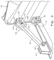
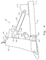
- FIGS. 2 and 4 show pitch link 104 attached to anchoring bracket 106 of blade 102 at a different pitch angle than that shown in Figs. 1 and 3 . More specifically, Figs. 1 and 3 show pitch link 104 attached to mounting bore 116B and, Figs. 2 and 4 show pitch link 104 attached to mounting bores 116A. Pitch link 104 may incorporate a variable length design such as a turnbuckle or cylinder to further alter the dimensions of blade assembly apparatus 100.
Landscapes
- Engineering & Computer Science (AREA)
- Mechanical Engineering (AREA)
- Mining & Mineral Resources (AREA)
- Civil Engineering (AREA)
- General Engineering & Computer Science (AREA)
- Structural Engineering (AREA)
- Operation Control Of Excavators (AREA)
Abstract
Description
- The present invention relates generally to work vehicles having a front blade configured to push materials such as soil, sand, rubble or other debris, and, more particularly, to an apparatus for selectively coupling such a blade mechanism to a work vehicle at multiple pitch angles.
- Bulldozers having front blades are well known. Generally, the blade is supported by one or more hydraulic cylinders used to push the blade forward and/or alter the pitch of the blade. Other bulldozers have a blade with a static pitch where an operator must disengage and re-engage the blade in order to alter the pitch angle of the blade relative to the frame and/or bulldozer.
- In prior art systems for static pitch bull dozers, a single mounting bore is disposed through an anchoring bracket on the rear of the blade and multiple, linearly arranged corresponding mounting bores are disposed on one end of an adjacent pitch link. The pitch of the blade is adjusted by selectively engaging the pitch link with a mounting bore on the mounting bracket. Such systems often include a plurality of retention holes disposed through the anchoring bracket relatively adjacent to the mounting bores.
- Other prior art systems can include a plurality of linearly arranged mounting bores through an anchoring bracket on the top of the push beam of the bulldozer. These systems can also have a plurality of retention holes disposed through the anchoring bracket relatively adjacent to the mounting bores.
- In both of the above described prior art designs, each retention hole adds to the cost of manufacturing the bulldozer. Additionally, any unused retention holes are open to the elements as the bulldozer is in use. Consequently, the retention holes are susceptible to oxidation which may render the retention hole unusable. Also, systems with mounting bores on the top of the push beam of the bulldozer are more susceptible to damage than arrangements on the back of the blade.
- Other prior art bulldozer blade assemblies require the use of an extendable turnbuckle. Extendable turnbuckles also add complexity to the overall design. Moreover, dirt and debris collected while using the bulldozer may negatively impact the functionality of such extendable turnbuckles. The extension mechanism of such turnbuckles is also susceptible to damage from oxidation.
- Thus, what is needed is an improved system for selectively mounting a blade at a desired pitch angle on a bulldozer.
- The present invention provides a multiple pitch bulldozer blade mounting system that includes a plurality of mounting bores arranged at a constant distance from a single retention hole.
- In one exemplary embodiment, the blade assembly of the present invention includes a push beam; a blade having a working side and a connection side; an anchoring bracket disposed on the connection side of the blade and having a plurality of mounting bores arranged along an arc around a retention hole; and a pitch link connected to the push beam and to the anchoring bracket using a retention pin configured to be removably placed through co-linear mounting bores on the pitch link and the anchoring bracket.
- An advantage of the present invention is that a single retention hole may be used on the anchoring bracket thereby obviating the need for multiple retention holes on the anchoring bracket or multiple mounting bores on the top of the push beam which can become damaged to the point of being unusable by debris or oxidation when the bulldozer is in use.
- Another advantage of the present invention is that it allows use of a standard cylinder instead of a cylinder with an extended tube for mounting to the top of a push beam with a plurality of mounting holes.
- Another advantage is that the present invention increases the overall robustness of the bulldozer attachment mechanism while retaining the ability for an end user to selectively alter the pitch of the blade.
- Another advantage of the present invention is that the overall cost of the system design is lower than the presumed cost of prior art products because a device constructed in accordance with the present invention does not require a longitudinally adjustable pitch link in order to achieve multiple pitch angles in the blade.
- Still another advantage of the present invention is that the full desired range of pitching angles may be achieved at any blade setting.
- The above-mentioned and other features and advantages of this invention, and the manner of attaining them, will become more apparent and the invention will be better understood by reference to the following description of an embodiments of the invention taken in conjunction with the accompanying drawings, wherein:
-
Fig. 1 shows a perspective view of a blade assembly apparatus according to an embodiment of the present invention with the blade attached to the pitch link at a first pitch angle; -
Fig. 2 shows a perspective view of the blade assembly apparatus according to the present invention with the blade attached to the pitch link at a second pitch angle; -
Fig. 3 shows a cross-sectional view of the blade assembly apparatus according to the present invention with the blade attached to the pitch link at the pitch angle shown inFig.1 ; and -
Fig. 4 shows a cross-sectional view of the blade assembly apparatus according to the present invention with the blade attached to the pitch link at the pitch angle shown inFig. 2 . - Corresponding reference characters indicate corresponding parts throughout the several views. The exemplary embodiment set forth herein is not to be construed as limiting the scope of the invention in any manner.
- Referring now to
Figs.1-4 , there is shown a perspective view of a blade assembly apparatus according to the present invention. As illustrated inFig. 1 ,blade assembly apparatus 100 generally includesblade 102;pitch link 104;anchoring bracket 106;additional anchoring bracket 108; andpush beam 110. -
Push beam 110 has afirst end 109 and asecond end 111.First end 109 ofpush beam 110 is pivotally attached toanchor bracket 108, which in turn is rigidly mounted to the connectingside 101 ofblade 102.Push beam 110 also hassecond end 111 fixedly attached toconnector 112. -
Pitch link 104 includes a first end 105 asecond end 107.First end 105 is fixedly, rotatably attached toconnector 112, which in turn is mounted to the top side ofpush beam 110.Second end 107 ofpitch link 104 includes a mounting bore (not shown) disposed therethrough.Second end 107 is selectively attached to anchoringbracket 106. - Anchoring
bracket 106 is rigidly connected to connectingside 101 ofblade 102, and includes a pair of parallel extendingarm members 114. At least onearm member 114 ofanchoring bracket 106 has aretention hole 118 and at least threemounting bores 116 disposed therethrough (threemounting bores 116 in the embodiment shown). Eachmounting bore 116 is disposed along an arcuate path aroundretention hole 118. In the illustrated embodiment, eachmounting bore 116 is disposed about a radius which is equi-distant fromretention bore 118. - Retention or "flag"
pin 120 is connected to the exterior ofupper anchoring bracket 106 and functions to pivotally connectpitch link 104 with a selectedmounting bore 116. As shown inFig. 1 ,flag pin 120 includes aflag 121 which is integrally connected with apin 123 which can be selectively disposed through one of themounting bores second end 107 ofpitch link 104. By selectively engagingflag pin 120 into a predeterminedmounting bore blade 102 relative topitch link 104 and/orpush beam 110 may be changed.Figs. 2 and4 show pitch link 104 attached to anchoringbracket 106 ofblade 102 at a different pitch angle than that shown inFigs. 1 and3 . More specifically,Figs. 1 and3 show pitch link 104 attached to mountingbore 116B and,Figs. 2 and4 show pitch link 104 attached to mountingbores 116A.Pitch link 104 may incorporate a variable length design such as a turnbuckle or cylinder to further alter the dimensions ofblade assembly apparatus 100. - While this invention has been described with respect to at least one embodiment, the present invention can be further modified within the spirit and scope of this disclosure. This application is therefore intended to cover any variations, uses, or adaptations of the invention using its general principles. Further, this application is intended to cover such departures from the present disclosure as come within known or customary practice in the art to which this invention pertains and which fall within the limits of the appended claims.
Claims (9)
- A blade assembly apparatus (100) for a vehicle, said blade assembly apparatus comprising:a push beam (110);a blade (102) having a working side and a connection side (101); anda pitch link (104) having a first end (105) and a second end (107), said first end (105) of said pitch link (104) pivotally connected to said push beam (110) and said second end (107) of said pitch link (104) having a mounting bore;characterized by:an anchoring bracket (106) disposed on the connection side (101) of said blade (102) and including a retention hole (118) and plurality of mounting bores (116), said mounting bores (116) arranged along an arc having a single radius about said retention hole (118); anda retention pin (120) configured to be removably disposed through one of said anchoring bracket mounting bores (116) and said pitch link mounting bore, thereby selectively attaching said pitch link (104) to said anchor member (106).
- The blade assembly apparatus (100) of claim 1, wherein the anchoring bracket (106) includes a pair of parallel extending arm members (114), and the second end (107) of the pitch link (104) is disposed between the arm members (114).
- The blade assembly apparatus (100) of claim 2, wherein each said arm member ( 114) includes the plurality of mounting bores (116), and said retention pin (120) passes through a pair of aligned said mounting bores (116) in each arm member (114).
- The blade assembly apparatus (100) of claim 1, wherein the anchoring bracket (106) comprises at least three mounting bores (116) disposed at an equal distance from said retention hole (118).
- The blade assembly apparatus (100) of claim 1, wherein the anchoring bracket (106) comprises three mounting bores (116) disposed at an equal distance about said retention hole (118).
- The blade assembly apparatus (100) of claim 1, wherein the retention pin (120) comprises a flag pin.
- The blade assembly apparatus (100) of claim 4, further comprising a bolt disposed through the flag pin and threadably connected to said anchoring bracket (106).
- The blade assembly apparatus (100) of claim 1, wherein the pitch link (104) has one of a fixed length and a variable length.
- The blade assembly apparatus (100) of claim 2, wherein the plurality of mounting bores (116) are oriented generally horizontally.
Applications Claiming Priority (1)
| Application Number | Priority Date | Filing Date | Title |
|---|---|---|---|
| US14/713,849 US9689142B2 (en) | 2015-05-15 | 2015-05-15 | Radial pattern mechanically adjustable blade pitch mount |
Publications (1)
| Publication Number | Publication Date |
|---|---|
| EP3093396A1 true EP3093396A1 (en) | 2016-11-16 |
Family
ID=56119291
Family Applications (1)
| Application Number | Title | Priority Date | Filing Date |
|---|---|---|---|
| EP16169713.1A Withdrawn EP3093396A1 (en) | 2015-05-15 | 2016-05-13 | Radial pattern mechanically adjustable blade pitch mount |
Country Status (2)
| Country | Link |
|---|---|
| US (1) | US9689142B2 (en) |
| EP (1) | EP3093396A1 (en) |
Families Citing this family (1)
| Publication number | Priority date | Publication date | Assignee | Title |
|---|---|---|---|---|
| US10087600B2 (en) * | 2016-03-10 | 2018-10-02 | Caterpillar Inc. | Pitch adjustment assembly for machine-mounted tool |
Citations (3)
| Publication number | Priority date | Publication date | Assignee | Title |
|---|---|---|---|---|
| US2573921A (en) * | 1946-08-17 | 1951-11-06 | Int Harvester Co | Scraper blade |
| US6354025B1 (en) * | 1998-08-04 | 2002-03-12 | Cives Corporation | Adjustable mounting arrangement for moldboard |
| US20110024143A1 (en) * | 2009-07-29 | 2011-02-03 | Steven Jay Ditzler | Blade Apparatus With Blade Pitch Adjustability |
Family Cites Families (7)
| Publication number | Priority date | Publication date | Assignee | Title |
|---|---|---|---|---|
| US2279869A (en) * | 1940-06-15 | 1942-04-14 | Glenn R Houston | Combination bulldozer and ripper |
| US2548350A (en) * | 1947-09-25 | 1951-04-10 | Claude L Combs | Graduated t-square |
| US2816375A (en) * | 1955-05-09 | 1957-12-17 | Anderson August Elmer | Auxiliary blade attachment for bulldozers |
| US3325924A (en) | 1964-05-14 | 1967-06-20 | Jr Oliver N Peck | Earth moving apparatus |
| US6364617B1 (en) * | 2000-01-31 | 2002-04-02 | Airmaster Fan Company | Toolless assembled fan |
| GB2491203B (en) | 2011-05-27 | 2013-10-02 | Caterpillar Inc | Work machine blade coupling |
| US20130087351A1 (en) | 2011-10-07 | 2013-04-11 | Bryan D. Sulzer | Dual Cylinders For Effecting Tilt And Pitch Functions Of A Dozer Blade |
-
2015
- 2015-05-15 US US14/713,849 patent/US9689142B2/en active Active
-
2016
- 2016-05-13 EP EP16169713.1A patent/EP3093396A1/en not_active Withdrawn
Patent Citations (3)
| Publication number | Priority date | Publication date | Assignee | Title |
|---|---|---|---|---|
| US2573921A (en) * | 1946-08-17 | 1951-11-06 | Int Harvester Co | Scraper blade |
| US6354025B1 (en) * | 1998-08-04 | 2002-03-12 | Cives Corporation | Adjustable mounting arrangement for moldboard |
| US20110024143A1 (en) * | 2009-07-29 | 2011-02-03 | Steven Jay Ditzler | Blade Apparatus With Blade Pitch Adjustability |
Also Published As
| Publication number | Publication date |
|---|---|
| US20160333546A1 (en) | 2016-11-17 |
| US9689142B2 (en) | 2017-06-27 |
Similar Documents
| Publication | Publication Date | Title |
|---|---|---|
| US8490711B2 (en) | Ripper assembly having a linkage assembly and an actuator | |
| US7891121B2 (en) | Earthworking implement | |
| US9873300B1 (en) | Trailer hitch apparatus with lateral shift capability | |
| EP2759187A1 (en) | Drawbar apparatus for coupling an earth-working tool to a frame of an agricultural implement | |
| EP2740341A1 (en) | Drawbar apparatus and agricultural implement with such an apparatus | |
| JPS6037338A (en) | Loader accessories | |
| US4463507A (en) | Grader blade attachment | |
| US4135583A (en) | Bulldozer blade | |
| BR102017019888B1 (en) | UNIVERSAL COUPLER AND WORKING MACHINE | |
| US2821217A (en) | Blade attachment for dozers | |
| US9689142B2 (en) | Radial pattern mechanically adjustable blade pitch mount | |
| US7540103B2 (en) | Blade attachment device | |
| EP3354801B1 (en) | Device for mounting attachments to excavator arms | |
| JP6612797B2 (en) | Cylinder device for construction machinery | |
| DE112016002112T5 (en) | WORK ARMING DEVICE FOR CONSTRUCTION MACHINE | |
| US20160356016A1 (en) | Frame for supporting a radiator guard of a machine | |
| US20150152613A1 (en) | Three point blade that offsets as it angles | |
| EP2712967A1 (en) | Angle detection device of construction machine | |
| EP3229576B1 (en) | A quick hitch assembly | |
| US2816375A (en) | Auxiliary blade attachment for bulldozers | |
| US7565758B2 (en) | Quick attach coupling device | |
| US4467876A (en) | Ripper tooth means | |
| US2232672A (en) | Blade mounting for earth moving apparatus | |
| EP2989882B1 (en) | Feederhouse arrangement for mounting a header to a combine | |
| CN202390114U (en) | Boom limit device and construction machinery |
Legal Events
| Date | Code | Title | Description |
|---|---|---|---|
| PUAI | Public reference made under article 153(3) epc to a published international application that has entered the european phase |
Free format text: ORIGINAL CODE: 0009012 |
|
| AK | Designated contracting states |
Kind code of ref document: A1 Designated state(s): AL AT BE BG CH CY CZ DE DK EE ES FI FR GB GR HR HU IE IS IT LI LT LU LV MC MK MT NL NO PL PT RO RS SE SI SK SM TR |
|
| AX | Request for extension of the european patent |
Extension state: BA ME |
|
| STAA | Information on the status of an ep patent application or granted ep patent |
Free format text: STATUS: REQUEST FOR EXAMINATION WAS MADE |
|
| 17P | Request for examination filed |
Effective date: 20170516 |
|
| RBV | Designated contracting states (corrected) |
Designated state(s): AL AT BE BG CH CY CZ DE DK EE ES FI FR GB GR HR HU IE IS IT LI LT LU LV MC MK MT NL NO PL PT RO RS SE SI SK SM TR |
|
| STAA | Information on the status of an ep patent application or granted ep patent |
Free format text: STATUS: THE APPLICATION IS DEEMED TO BE WITHDRAWN |
|
| 18D | Application deemed to be withdrawn |
Effective date: 20170517 |