EP3093173A1 - Middle insert and glass window - Google Patents
Middle insert and glass window Download PDFInfo
- Publication number
- EP3093173A1 EP3093173A1 EP14878339.2A EP14878339A EP3093173A1 EP 3093173 A1 EP3093173 A1 EP 3093173A1 EP 14878339 A EP14878339 A EP 14878339A EP 3093173 A1 EP3093173 A1 EP 3093173A1
- Authority
- EP
- European Patent Office
- Prior art keywords
- opening
- seal
- middle insert
- light decoration
- decoration strip
- Prior art date
- Legal status (The legal status is an assumption and is not a legal conclusion. Google has not performed a legal analysis and makes no representation as to the accuracy of the status listed.)
- Granted
Links
Images


Classifications
-
- B—PERFORMING OPERATIONS; TRANSPORTING
- B60—VEHICLES IN GENERAL
- B60J—WINDOWS, WINDSCREENS, NON-FIXED ROOFS, DOORS, OR SIMILAR DEVICES FOR VEHICLES; REMOVABLE EXTERNAL PROTECTIVE COVERINGS SPECIALLY ADAPTED FOR VEHICLES
- B60J10/00—Sealing arrangements
- B60J10/15—Sealing arrangements characterised by the material
- B60J10/18—Sealing arrangements characterised by the material provided with reinforcements or inserts
-
- B—PERFORMING OPERATIONS; TRANSPORTING
- B60—VEHICLES IN GENERAL
- B60J—WINDOWS, WINDSCREENS, NON-FIXED ROOFS, DOORS, OR SIMILAR DEVICES FOR VEHICLES; REMOVABLE EXTERNAL PROTECTIVE COVERINGS SPECIALLY ADAPTED FOR VEHICLES
- B60J10/00—Sealing arrangements
- B60J10/20—Sealing arrangements characterised by the shape
- B60J10/26—Sealing arrangements characterised by the shape characterised by the surface shape
- B60J10/265—Sealing arrangements characterised by the shape characterised by the surface shape the surface being primarily decorative
-
- B—PERFORMING OPERATIONS; TRANSPORTING
- B60—VEHICLES IN GENERAL
- B60J—WINDOWS, WINDSCREENS, NON-FIXED ROOFS, DOORS, OR SIMILAR DEVICES FOR VEHICLES; REMOVABLE EXTERNAL PROTECTIVE COVERINGS SPECIALLY ADAPTED FOR VEHICLES
- B60J10/00—Sealing arrangements
- B60J10/45—Assembling sealing arrangements with vehicle parts
-
- B—PERFORMING OPERATIONS; TRANSPORTING
- B60—VEHICLES IN GENERAL
- B60J—WINDOWS, WINDSCREENS, NON-FIXED ROOFS, DOORS, OR SIMILAR DEVICES FOR VEHICLES; REMOVABLE EXTERNAL PROTECTIVE COVERINGS SPECIALLY ADAPTED FOR VEHICLES
- B60J10/00—Sealing arrangements
- B60J10/70—Sealing arrangements specially adapted for windows or windscreens
-
- B—PERFORMING OPERATIONS; TRANSPORTING
- B60—VEHICLES IN GENERAL
- B60R—VEHICLES, VEHICLE FITTINGS, OR VEHICLE PARTS, NOT OTHERWISE PROVIDED FOR
- B60R13/00—Elements for body-finishing, identifying, or decorating; Arrangements or adaptations for advertising purposes
- B60R13/04—External Ornamental or guard strips; Ornamental inscriptive devices thereon
-
- E—FIXED CONSTRUCTIONS
- E06—DOORS, WINDOWS, SHUTTERS, OR ROLLER BLINDS IN GENERAL; LADDERS
- E06B—FIXED OR MOVABLE CLOSURES FOR OPENINGS IN BUILDINGS, VEHICLES, FENCES OR LIKE ENCLOSURES IN GENERAL, e.g. DOORS, WINDOWS, BLINDS, GATES
- E06B7/00—Special arrangements or measures in connection with doors or windows
- E06B7/16—Sealing arrangements on wings or parts co-operating with the wings
Definitions
- the present invention relates to the field of mounting a decoration strip on a glass window, and in particular to a middle insert which is used for mounting a light decoration strip on a seal of automobile glass, and a glass window comprising the middle insert, the light decoration strip and the seal.
- a light decoration strip for an automobile window can improve the overall aesthetics of the automobile, and promote the grade of the automobile.
- the light decoration strip is usually mounted on the seal surrounding automobile window glass before delivery of the window glass.
- a middle insert is usually adopted to fixedly connect the light decoration strip and the seal together, such that the window glass on which the light decoration strip is mounted can be easily installed into an automobile window after being delivered to an assembling plant, and a step of mounting the light decoration strip in the assembling plant is omitted.
- Chinese Patent CN1287531A disclosed a window unit mounted in a predesigned opening of motor vehicles and such like.
- the window unit comprises a window pane and a frame which is integratedly molded on the window pane.
- Retaining devices for retaining add-on parts are provided at several peripheral locations of the frame.
- Each retaining device is formed by a retaining strip and a retaining clip.
- the retaining strip is arranged on the outer side of the frame and permanently joined to the frame, for example by being partly molded in the frame.
- the retaining clip comprises an elongate base, on both longitudinal sides of which retaining wings and detent wings are positioned.
- the retaining wings serve for removably anchoring the retaining clips on the retaining strips, and the detent wings serve for removably connecting the add-on parts to the frame.
- the retaining device of this patent is equivalent to a middle insert.
- the intermediate fastening device comprises at least one clip having at least one upstream cooperating part configured to cooperate with the profiled strip and a downstream cooperating part configured to cooperate with the attachment.
- the upstream cooperating part comprises a plurality of catching tabs connected by a base part. The end of each tab is deformable. The tabs are deformed by applying a force to the ends of the tabs toward the material of the profiled strip in two opposed directions so as to penetrate the material of the profiled strip during the step of fastening the clip onto the profiled strip.
- the intermediate fastening device of this patent is equivalent to a middle insert.
- the devices equivalent to the middle insert disclosed by the two above patents have following disadvantages. Firstly, when being mounted, both ends of the light decoration strip need to be pressed downward at the same time to get snapped in, thereby resulting in difficult assembling operation, and after getting snapped in, the light decoration strip is not firmly clamped to the device equivalent to the middle insert and is easy to loosen, release or remove. Secondly, the device equivalent to the middle insert has complex shapes, such that the manufacturing process and installing process thereof become complex, thereby increasing the manufacturing cost.
- the light decoration strip cannot be firmly fixed due to the fixing way between the light decoration strip and the device equivalent to the middle insert, such that the shaking of the automobile itself may easily cause abnormal noise of the light decoration strip, thereby on one hand affecting the passengers' mood, and on the other hand reducing the service life thereof due to friction.
- the light decoration strip and the device equivalent to the middle insert is not longitudinally positioned relative to each other, such that the light decoration strip which is merely mounted on single edge of the glass may move longitudinally, thereby affecting the mounting accuracy of the light decoration strip.
- the technical problem to be solved by the present invention is to provide a middle insert, and a glass window comprising the middle insert, to overcome the disadvantages of existing middle insert, such as clamping unfirmly, having a complex structure, easily causing abnormal noise and easily sliding.
- the technical solution adopted in the present invention is a middle insert for mounting a light decoration strip on a seal of a glass window, comprising a first end part provided with a first opening, a second end part provided with a second opening, and a connecting part used for connecting the first end part and the second end part; wherein the first opening and the second opening face the outsides of the first and second end parts, respectively.
- the opening depth of the first opening is greater than that of the second opening.
- a barrier part integratedly extends outwards from the underside of the first opening or the second opening; a groove opening upward is formed by the barrier part and the first opening or the second opening together; a projecting part is provided on the outer surface of the barrier part.
- At least two auxiliary holes are provided on the upper surface of the connecting part.
- the connecting part is provided with at least one concave section.
- the present invention further provides a glass window comprising a glass pane, a seal molded at least partially on the periphery of the glass pane, a middle insert fixed on the seal, and a light decoration strip mounted on the seal via the middle insert and comprising a first fixing part and a second fixing part; wherein the middle insert comprises a first end part provided with a first opening, a second end part provided with a second opening, and a connecting part used for connecting the first end part and the second end part; the first opening and the second opening face the outsides of the first and second end parts, respectively; the first fixing part is clamped into the first opening and the second fixing part is clamped into the second opening.
- the opening depth of the first opening is greater than that of the second opening.
- a barrier part integratedly extends outwards from the underside of the first opening or the second opening; a groove opening upward is formed by the barrier part and the first opening or the second opening together; a projecting part is provided on the outer surface of the barrier part; the projecting part is at least partially enwrapped by the seal.
- the middle insert and the seal are fixed on the periphery of the glass pane by integratedly molding.
- At least two auxiliary holes are provided on the upper surface of the connecting part of the middle insert.
- auxiliary holes are filled with binding material.
- the connecting part of the middle insert is at least partially enwrapped by the seal.
- the seal enwrapping the connecting part is at least partially provided with a bulge or bulges on the upper surface; the bulge or bulges extend in the longitudinal direction of the light decoration strip; the clearance between the upper surface of the bulge or bulges and the lower surface of the light decoration strip is less than ⁇ 0.5mm.
- the connecting part of the middle insert is provided with at least one concave section.
- a double-sided tape is provided between the portion of the upper surface of the seal where the middle insert is not provided and the lower surface of the light decoration strip.
- At least one binding groove is provided on the portion of the upper surface of the seal where the middle insert is not provided; the binding groove is filled with binding material.
- the middle insert according to the present invention is simple in structure such that both complexity and labor cost are reduced.
- the opening depth of the first opening is simply mounted and clamped firmly.
- the clamping intensity of the light decoration strip is enhanced, so that it is guaranteed that the light decoration strip is difficult to loosen, release or remove.
- the light decoration strip is prevented from freely sliding on the seal, thereby guaranteeing the mounting accuracy of the light decoration strip at the edge and avoiding the abnormal noise.
- a middle insert 1 is used for mounting a light decoration strip 2 on a seal 3 of a glass window.
- the seal 3 is molded onto the periphery of a glass pane 4 by a specific apparatus or device. It is well known to the person skilled in the art that the seal 3 may be provided on the whole periphery of the glass pane 4, or may be provided on a part of the periphery of the glass pane 4, or even may be provided anywhere of the glass pane 4.
- the material of the seal 3 is conventionally chosen from thermo-plastic material (such as PVC, TPE etc.), polyurethane or synthetic rubber of EPDM type and so on, but not limited to them, and other suitable material is also applicable.
- the light decoration strip 2 may be provided on the part of the seal 3 which is visible from the exterior of the automobile.
- the light decoration strip 2 is used for covering the part of the seal 3 which is visible from the exterior of the automobile.
- the light decoration strip is specified in the present invention, the light decoration strip merely serves as one type of decoration of the automobile, and thus it is understood that the middle insert according to the present invention may be suitable for other types of decoration, even automobile glass attachment.
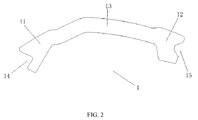
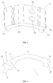
- the middle insert 1 For mounting the light decoration strip 2 on the seal 3 more firmly, the middle insert 1 is provided by the present invention. As shown in FIG. 2 and FIG. 3 , the middle insert 1 comprises a first end part 11, a second end part 12 and a connecting part 13 used for connecting the first end part 11 and the second end part 12.
- the first end part 11 is provided with a first opening 14.
- the second end part12 is provided with a second opening 15.
- the first opening 14 and the second opening 15 face the outsides of the first and second end parts, respectively.
- the first opening 14 and the second opening 15 is used for clamping the light decoration strip 2, thereby mounting the light decoration strip 2 on the seal 3.
- the opening depth of the first opening 14 is greater than that of the second opening 15.
- the first opening 14 and the second opening 15 are arranged to face the outsides of the first and second end parts respectively and downward, i.e. toward the direction away from the light decoration strip 2, so that the light decoration strip 2 can be mounted more firmly.
- the first opening 14 and the second opening 15 according to the present invention are described as two openings at both ends of the middle insert 1 for convenience, but the respective positions are not limited in practical application, which does not limit the scope of protection of the present invention.
- a barrier part 16 integratedly extends outwards from the underside of the first opening 14.
- a groove 17 opening upward is formed by the barrier part 16 and the first opening 14 together.
- a projecting part 18 is provided on the outer surface of the barrier part 16. It is understood that the barrier part 16 and the projecting part 18 may also be provided under the second opening 15, and a groove (not shown) opening upward may be formed by the barrier part 16 and the second opening 15 together, with a projecting part 18 provided on the outer surface of the barrier part 16.
- the groove 17 facilitates clamping the light decoration strip 2 into the middle insert 1.
- the projecting part 18 is at least partially enwrapped when being integratedly molded with the seal 3, which would enhance the connecting intensity between the middle insert 1 and the seal 3, thereby mounting the middle insert 1 on the seal 3 more firmly.
- auxiliary holes 19 are provided on the upper surface of the connecting part 13.
- the auxiliary holes 19 are used to position the middle insert 1 when the middle insert 1 and the seal 3 are integratedly molded together, thereby guaranteeing the mounting accuracy of the middle insert 1 on the seal 3. It is understood that the auxiliary holes 19 may be through holes, or blind holes, according to practical manufacturing requirements.
- the present invention further provides a glass window comprising the above middle insert 1.
- the glass window comprises the middle insert 1, the light decoration strip 2, the seal 3 and the glass pane 4.
- the middle insert 1 is fixed on the seal 3.
- the light decoration strip 2 comprises a first fixing part 21 and a second fixing part 22.
- the light decoration strip 2 is mounted on the seal 3 via the middle insert 1.
- the seal 3 is at least partially fixed on the periphery of the glass pane 4.
- the glass pane 4 according to the present invention is not limited to silicate glass. Other suitable transparent pane which could be installing in the opening portion of the automobile body, such as organic resin glass including PMMA, PC etc., is also applicable.
- the middle insert 1 comprises the first end part 11, the second end part 12 and the connecting part 13 used for connecting the first end part 11 and the second end part 12.
- the first end part 11 is provided with the first opening 14.
- the second end part12 is provided with the second opening 15.
- the first opening 14 and the second opening 15 face the outsides of the first and second end parts, respectively.
- the first fixing part 21 is clamped into the first opening 14, and the second fixing part 22 is clamped into the second opening 15, thereby mounting the light decorating strip 2 on the seal 3.
- the opening depth of the first opening 14 is greater than that of the second opening 15.
- the first opening 14 and the second opening 15 are arranged to face the outsides of the first and second end parts respectively and downward, i.e. toward the direction away from the light decoration strip 2, so that the light decoration strip 2 can be mounted more firmly.
- the first opening 14 and the second opening 15 according to the present invention are described as two openings at both ends of the middle insert 1 for convenience, but the respective positions are not limited in practical application, which does not limit the scope of protection of the present invention.
- a barrier part 16 integratedly extends outwards from the underside of the first opening 14.
- a groove 17 opening upward is formed by the barrier part 16 and the first opening 14 together.
- a projecting part 18 is provided on the outer surface of the barrier part 16.
- the first fixing part 21 is inserted in the groove 17 and clamped into the first opening 14, and the projecting part 18 is at least partially enwrapped by the seal 3.
- the barrier part 16 and the projecting part 18 may also be provided under the second opening 15, and a groove (not shown) opening upward may be formed by the barrier part 16 and the second opening 15 together.
- the second fixing part 22 is inserted in the groove (not shown) and clamped into the second opening 15, and the projecting part 18 is at least partially enwrapped by the seal 3.
- the groove 17 facilitates clamping the light decoration strip 2 into the middle insert 1.
- the projecting part 18 is at least partially enwrapped when being integratedly molded with the seal 3, which would enhance the connecting intensity between the middle insert 1 and the seal 3, thereby mounting the middle insert 1 on the seal 3 more firmly.
- the middle insert 1 and the seal 3 are fixed on the periphery of the glass pane 4 by integratedly molding, so that the middle insert 1 and the seal 3 can be manufactured as a whole, and further assembling operation is unnecessary, thereby reducing the manufacturing time and labor.
- auxiliary holes 19 are provided on the upper surface of the connecting part 13.
- the auxiliary holes 19 are used to position the middle insert 1 when the middle insert 1 and the seal 3 are integratedly molded together, thereby guaranteeing the mounting accuracy of the middle insert 1 on the seal 3.
- the auxiliary holes 19 may be through holes, or blind holes, according to practical manufacturing requirements.
- the auxiliary holes 19 may be filled with binding material (not shown) which may be PU adhesive, silicon adhesive or other adhesive, or may be selected according to the material of the middle insert 1, the light decoration strip 2 and the seal 3. Generally, the binding force between the binding material and the light decoration strip 2 is relatively strong, but the binding force between the binding material and the seal 3 is weak.
- the binding material has good selectivity.
- the connecting part 13 of the middle insert 1 is at least partially enwrapped by the seal 3.
- the connecting part 13 is enwrapped by an enwrapping part 31 of the seal 3.
- the enwrapping part 31 is located between the middle insert 1 and the light decoration strip 2.
- the enwrapping part 31 can enhance the connecting intensity between the middle insert 1 and the seal 3, thereby mounting the middle insert 1 on the seal 3 more firmly.
- the seal 3 i.e. the enwrapping part 31
- enwrapping the connecting part 13 is at least partially provided with a bulge or bulges 32 on the upper surface.
- the bulge or bulges 32 extend in the longitudinal direction of the light decoration strip 2.
- the clearance between the upper surface of the bulge or bulges 32 and the lower surface of the light decoration strip 2 is less than ⁇ 0.5mm.
- the light decoration strip 2 is under tense state when the bulge or bulges 32 and the corresponding lower surface of the light decoration strip 2 are well fitted together, which enhances the clamping intensity between the middle insert 1 and the light decoration strip 2, thereby guaranteeing that the light decoration strip 2 is difficult to loosen or release. Moreover, the force of the bulge or bulges 32 acting on the light decoration strip 2 is enhanced with the deformation of the light decoration strip 2, thereby guaranteeing that the light decoration strip 2 is difficult to remove.
- a double-sided tape 5 is provided between the portion of the upper surface of the seal 3 where the middle insert 1 is not provided and the lower surface of the light decoration strip 2.
- One side of the double-sided tape 5 is adhered to the upper surface of the seal 3, and the other side is adhered to the lower surface of the light decoration strip 2, so that the light decoration strip 2 can be mounted more firmly, thereby avoiding the abnormal noise of the light decoration strip 2 caused by the shaking of the automobile itself, preventing the light decoration strip 2 from freely sliding on the seal 3, and guaranteeing the mounting accuracy.
- At least one binding groove 6 is provided on the portion of the upper surface of the seal 3 where the middle insert 1 is not provided.
- the binding groove 6 is filled with the binding material 61.
- the binding material 61 may be PU adhesive, silicon adhesive or other adhesive. or may be selected according to the material of the middle insert 1, the light decoration strip 2 and the seal 3.
- the upper surface of the binding material 61 and the lower surface of the light decoration strip 2 are bound together, so that the light decoration strip 2 can be mounted more firmly, thereby avoiding the abnormal noise of the light decoration strip 2 caused by the shaking of the automobile itself, preventing the light decoration strip 2 from freely sliding on the seal 3, and guaranteeing the mounting accuracy.
- the glass window may be specifically designed to have different structures and shapes, and accordingly the middle insert 1 is designed differently.
- the connecting part 13 of the middle insert 1 is provided with at least one concave section.
- the connecting part 13 of the middle insert 1 is provided with one concave section 131.
- the connecting part 13 of the middle insert 1 is provided with two concave sections, i.e. the first concave section 132 and the second concave section 133.
- the other parts of the middle insert 1 as shown in FIG. 8 and FIG. 9 are substantially identical with those of the middle insert 1 as shown in FIG.
- the middle insert 1 with concave section(s) is adaptable to glass windows in different designs, thereby increasing the types of glass windows.
Landscapes
- Engineering & Computer Science (AREA)
- Mechanical Engineering (AREA)
- Civil Engineering (AREA)
- Structural Engineering (AREA)
- Securing Of Glass Panes Or The Like (AREA)
- Seal Device For Vehicle (AREA)
Abstract
Description
- This present application claims the benefit of priority to Chinese Patent Application No.
201410005813.X - The present invention relates to the field of mounting a decoration strip on a glass window, and in particular to a middle insert which is used for mounting a light decoration strip on a seal of automobile glass, and a glass window comprising the middle insert, the light decoration strip and the seal.
- With development of automobile technology, requirements from people on security, comfortability and aesthetics of an automobile are higher and higher. A light decoration strip for an automobile window, as a type of decoration of the automobile, can improve the overall aesthetics of the automobile, and promote the grade of the automobile. The light decoration strip is usually mounted on the seal surrounding automobile window glass before delivery of the window glass. According to the prior art, a middle insert is usually adopted to fixedly connect the light decoration strip and the seal together, such that the window glass on which the light decoration strip is mounted can be easily installed into an automobile window after being delivered to an assembling plant, and a step of mounting the light decoration strip in the assembling plant is omitted.
- According to the prior art, Chinese Patent
CN1287531A disclosed a window unit mounted in a predesigned opening of motor vehicles and such like. The window unit comprises a window pane and a frame which is integratedly molded on the window pane. Retaining devices for retaining add-on parts are provided at several peripheral locations of the frame. Each retaining device is formed by a retaining strip and a retaining clip. The retaining strip is arranged on the outer side of the frame and permanently joined to the frame, for example by being partly molded in the frame. The retaining clip comprises an elongate base, on both longitudinal sides of which retaining wings and detent wings are positioned. The retaining wings serve for removably anchoring the retaining clips on the retaining strips, and the detent wings serve for removably connecting the add-on parts to the frame. The retaining device of this patent is equivalent to a middle insert. - Moreover, another Chinese Patent
CN102272463A disclosed an intermediate fastening device for fitting an attachment, such as a trim, on a profiled strip. The intermediate fastening device comprises at least one clip having at least one upstream cooperating part configured to cooperate with the profiled strip and a downstream cooperating part configured to cooperate with the attachment. The upstream cooperating part comprises a plurality of catching tabs connected by a base part. The end of each tab is deformable. The tabs are deformed by applying a force to the ends of the tabs toward the material of the profiled strip in two opposed directions so as to penetrate the material of the profiled strip during the step of fastening the clip onto the profiled strip. The intermediate fastening device of this patent is equivalent to a middle insert. - However, in practical use, the devices equivalent to the middle insert disclosed by the two above patents have following disadvantages. Firstly, when being mounted, both ends of the light decoration strip need to be pressed downward at the same time to get snapped in, thereby resulting in difficult assembling operation, and after getting snapped in, the light decoration strip is not firmly clamped to the device equivalent to the middle insert and is easy to loosen, release or remove. Secondly, the device equivalent to the middle insert has complex shapes, such that the manufacturing process and installing process thereof become complex, thereby increasing the manufacturing cost. Thirdly, the light decoration strip cannot be firmly fixed due to the fixing way between the light decoration strip and the device equivalent to the middle insert, such that the shaking of the automobile itself may easily cause abnormal noise of the light decoration strip, thereby on one hand affecting the passengers' mood, and on the other hand reducing the service life thereof due to friction. Fourthly, the light decoration strip and the device equivalent to the middle insert is not longitudinally positioned relative to each other, such that the light decoration strip which is merely mounted on single edge of the glass may move longitudinally, thereby affecting the mounting accuracy of the light decoration strip.
- The technical problem to be solved by the present invention is to provide a middle insert, and a glass window comprising the middle insert, to overcome the disadvantages of existing middle insert, such as clamping unfirmly, having a complex structure, easily causing abnormal noise and easily sliding.
- To overcome the technical problem, the technical solution adopted in the present invention is a middle insert for mounting a light decoration strip on a seal of a glass window, comprising a first end part provided with a first opening, a second end part provided with a second opening, and a connecting part used for connecting the first end part and the second end part; wherein the first opening and the second opening face the outsides of the first and second end parts, respectively.
- Preferably, the opening depth of the first opening is greater than that of the second opening.
- Preferably, a barrier part integratedly extends outwards from the underside of the first opening or the second opening; a groove opening upward is formed by the barrier part and the first opening or the second opening together; a projecting part is provided on the outer surface of the barrier part.
- Preferably, at least two auxiliary holes are provided on the upper surface of the connecting part.
- Preferably, the connecting part is provided with at least one concave section.
- Moreover, the present invention further provides a glass window comprising a glass pane, a seal molded at least partially on the periphery of the glass pane, a middle insert fixed on the seal, and a light decoration strip mounted on the seal via the middle insert and comprising a first fixing part and a second fixing part; wherein the middle insert comprises a first end part provided with a first opening, a second end part provided with a second opening, and a connecting part used for connecting the first end part and the second end part; the first opening and the second opening face the outsides of the first and second end parts, respectively; the first fixing part is clamped into the first opening and the second fixing part is clamped into the second opening..
- Preferably, the opening depth of the first opening is greater than that of the second opening.
- Preferably, a barrier part integratedly extends outwards from the underside of the first opening or the second opening; a groove opening upward is formed by the barrier part and the first opening or the second opening together; a projecting part is provided on the outer surface of the barrier part; the projecting part is at least partially enwrapped by the seal.
- Preferably, the middle insert and the seal are fixed on the periphery of the glass pane by integratedly molding.
- Preferably, at least two auxiliary holes are provided on the upper surface of the connecting part of the middle insert.
- Furthermore, the auxiliary holes are filled with binding material.
- Preferably, the connecting part of the middle insert is at least partially enwrapped by the seal.
- Furthermore, the seal enwrapping the connecting part is at least partially provided with a bulge or bulges on the upper surface; the bulge or bulges extend in the longitudinal direction of the light decoration strip; the clearance between the upper surface of the bulge or bulges and the lower surface of the light decoration strip is less than ±0.5mm.
- Furthermore, the connecting part of the middle insert is provided with at least one concave section.
- Furthermore, a double-sided tape is provided between the portion of the upper surface of the seal where the middle insert is not provided and the lower surface of the light decoration strip.
- Furthermore, at least one binding groove is provided on the portion of the upper surface of the seal where the middle insert is not provided; the binding groove is filled with binding material.
- By adopting the above mentioned technical solutions the present invention has the following advantages. The middle insert according to the present invention is simple in structure such that both complexity and labor cost are reduced. By designing the opening depth of the first opening to be greater than that of the second opening, the light decoration strip is simply mounted and clamped firmly. By arranging a bulge or bulges on the seal, the clamping intensity of the light decoration strip is enhanced, so that it is guaranteed that the light decoration strip is difficult to loosen, release or remove. By arranging a binding groove and bind material or a double-sided tape on the seal, the light decoration strip is prevented from freely sliding on the seal, thereby guaranteeing the mounting accuracy of the light decoration strip at the edge and avoiding the abnormal noise.
-
-
FIG. 1 is a partial cross-section view of a glass window comprising a middle insert, a light decoration strip and a seal according to the present invention; -
FIG. 2 is a front view of the middle insert according to the present invention; -
FIG. 3 is a structural schematic diagram of the middle insert according to the present invention; -
FIG. 4 is a front view of the middle insert provided with a barrier part and a projecting part according to the present invention; -
FIG. 5 is a structural schematic diagram of the middle insert provided with a barrier part and a projecting part according to the present invention; -
FIG. 6 is a partial cross-section view of the glass window according to the present invention where a double-sided tape is provided on the seal; -
FIG. 7 is a partial cross-section view of the glass window according to the present invention where binding grooves and binding material are provided on the seal; -
FIG. 8 is a partial cross-section view showing that a concave section is provided on connecting part of the middle insert, according to the present invention; -
FIG. 9 is a partial cross-section view showing that two concave sections are provided on the connecting part of the middle insert, according to the present invention. - Reference list: 1, middle insert; 11, first end part; 12, second end part; 13, connecting part; 14, first opening; 15, second opening; 16, barrier part; 17, groove; 18, projecting part; 19, auxiliary hole; 2, light decoration strip; 21, first fixing part; 22, second fixing part; 3, seal; 31, enwrapping part; 32, bulge; 4, glass pane; 5, double-sided tape; 6, binding groove; 61, binding material; 131, concave section; 132, first concave section; 133, second concave section.
- Further description of the present invention will be illustrated hereinafter in conjunction with the drawings.
- Referring to
FIG. 1 , amiddle insert 1 according to the present invention is used for mounting alight decoration strip 2 on aseal 3 of a glass window. Theseal 3 is molded onto the periphery of aglass pane 4 by a specific apparatus or device. It is well known to the person skilled in the art that theseal 3 may be provided on the whole periphery of theglass pane 4, or may be provided on a part of the periphery of theglass pane 4, or even may be provided anywhere of theglass pane 4. The material of theseal 3 is conventionally chosen from thermo-plastic material (such as PVC, TPE etc.), polyurethane or synthetic rubber of EPDM type and so on, but not limited to them, and other suitable material is also applicable. - For improving the overall aesthetics of the automobile and promoting the grade of the automobile, the
light decoration strip 2 may be provided on the part of theseal 3 which is visible from the exterior of the automobile. Thelight decoration strip 2 is used for covering the part of theseal 3 which is visible from the exterior of the automobile. Although the light decoration strip is specified in the present invention, the light decoration strip merely serves as one type of decoration of the automobile, and thus it is understood that the middle insert according to the present invention may be suitable for other types of decoration, even automobile glass attachment. - For mounting the
light decoration strip 2 on theseal 3 more firmly, themiddle insert 1 is provided by the present invention. As shown inFIG. 2 andFIG. 3 , themiddle insert 1 comprises afirst end part 11, asecond end part 12 and a connectingpart 13 used for connecting thefirst end part 11 and thesecond end part 12. Thefirst end part 11 is provided with afirst opening 14. The second end part12 is provided with asecond opening 15. Thefirst opening 14 and thesecond opening 15 face the outsides of the first and second end parts, respectively. Thefirst opening 14 and thesecond opening 15 is used for clamping thelight decoration strip 2, thereby mounting thelight decoration strip 2 on theseal 3. - Preferably, the opening depth of the
first opening 14 is greater than that of thesecond opening 15. When being mounted, firstly thelight decoration strip 2 is clamped into thefirst opening 14 with relatively greater open depth, then into thesecond opening 15 with relatively smaller open depth, such that thelight decoration strip 2 is simply mounted and clamped firmly. Moreover, preferably, thefirst opening 14 and thesecond opening 15 are arranged to face the outsides of the first and second end parts respectively and downward, i.e. toward the direction away from thelight decoration strip 2, so that thelight decoration strip 2 can be mounted more firmly. Thefirst opening 14 and thesecond opening 15 according to the present invention are described as two openings at both ends of themiddle insert 1 for convenience, but the respective positions are not limited in practical application, which does not limit the scope of protection of the present invention. - As shown in
FIG. 4 andFIG. 5 , abarrier part 16 integratedly extends outwards from the underside of thefirst opening 14. Agroove 17 opening upward is formed by thebarrier part 16 and thefirst opening 14 together. A projectingpart 18 is provided on the outer surface of thebarrier part 16. It is understood that thebarrier part 16 and the projectingpart 18 may also be provided under thesecond opening 15, and a groove (not shown) opening upward may be formed by thebarrier part 16 and thesecond opening 15 together, with a projectingpart 18 provided on the outer surface of thebarrier part 16. Thegroove 17 facilitates clamping thelight decoration strip 2 into themiddle insert 1. The projectingpart 18 is at least partially enwrapped when being integratedly molded with theseal 3, which would enhance the connecting intensity between themiddle insert 1 and theseal 3, thereby mounting themiddle insert 1 on theseal 3 more firmly. - As shown in
FIG. 3 andFIG. 5 , at least twoauxiliary holes 19 are provided on the upper surface of the connectingpart 13. The auxiliary holes 19 are used to position themiddle insert 1 when themiddle insert 1 and theseal 3 are integratedly molded together, thereby guaranteeing the mounting accuracy of themiddle insert 1 on theseal 3. It is understood that theauxiliary holes 19 may be through holes, or blind holes, according to practical manufacturing requirements. - The middle insert is described in detail in the above embodiments. Moreover, the present invention further provides a glass window comprising the above
middle insert 1. As shown inFIG. 1 , the glass window comprises themiddle insert 1, thelight decoration strip 2, theseal 3 and theglass pane 4. Themiddle insert 1 is fixed on theseal 3. Thelight decoration strip 2 comprises a first fixingpart 21 and a second fixingpart 22. Thelight decoration strip 2 is mounted on theseal 3 via themiddle insert 1. Theseal 3 is at least partially fixed on the periphery of theglass pane 4. Theglass pane 4 according to the present invention is not limited to silicate glass. Other suitable transparent pane which could be installing in the opening portion of the automobile body, such as organic resin glass including PMMA, PC etc., is also applicable. - As shown in
FIG. 2 andFIG. 3 , themiddle insert 1 comprises thefirst end part 11, thesecond end part 12 and the connectingpart 13 used for connecting thefirst end part 11 and thesecond end part 12. Thefirst end part 11 is provided with thefirst opening 14. The second end part12 is provided with thesecond opening 15. Thefirst opening 14 and thesecond opening 15 face the outsides of the first and second end parts, respectively. The first fixingpart 21 is clamped into thefirst opening 14, and the second fixingpart 22 is clamped into thesecond opening 15, thereby mounting thelight decorating strip 2 on theseal 3. - Preferably, the opening depth of the
first opening 14 is greater than that of thesecond opening 15. When thelight decoration strip 2 being mounted, firstly the first fixingpart 21 is clamped into thefirst opening 14, and then the second fixingpart 22 is clamped into thesecond opening 15, such that thelight decoration strip 2 is simply mounted and clamped firmly. Moreover, preferably, thefirst opening 14 and thesecond opening 15 are arranged to face the outsides of the first and second end parts respectively and downward, i.e. toward the direction away from thelight decoration strip 2, so that thelight decoration strip 2 can be mounted more firmly. Thefirst opening 14 and thesecond opening 15 according to the present invention are described as two openings at both ends of themiddle insert 1 for convenience, but the respective positions are not limited in practical application, which does not limit the scope of protection of the present invention. - As shown in
FIG. 4 andFIG. 5 , abarrier part 16 integratedly extends outwards from the underside of thefirst opening 14. Agroove 17 opening upward is formed by thebarrier part 16 and thefirst opening 14 together. A projectingpart 18 is provided on the outer surface of thebarrier part 16. As shown inFIG.1 , the first fixingpart 21 is inserted in thegroove 17 and clamped into thefirst opening 14, and the projectingpart 18 is at least partially enwrapped by theseal 3. It is understood that thebarrier part 16 and the projectingpart 18 may also be provided under thesecond opening 15, and a groove (not shown) opening upward may be formed by thebarrier part 16 and thesecond opening 15 together. Thesecond fixing part 22 is inserted in the groove (not shown) and clamped into thesecond opening 15, and the projectingpart 18 is at least partially enwrapped by theseal 3. Thegroove 17 facilitates clamping thelight decoration strip 2 into themiddle insert 1. The projectingpart 18 is at least partially enwrapped when being integratedly molded with theseal 3, which would enhance the connecting intensity between themiddle insert 1 and theseal 3, thereby mounting themiddle insert 1 on theseal 3 more firmly. - Preferably, the
middle insert 1 and theseal 3 are fixed on the periphery of theglass pane 4 by integratedly molding, so that themiddle insert 1 and theseal 3 can be manufactured as a whole, and further assembling operation is unnecessary, thereby reducing the manufacturing time and labor. - As shown in
FIG. 3 andFIG. 5 , at least twoauxiliary holes 19 are provided on the upper surface of the connectingpart 13. The auxiliary holes 19 are used to position themiddle insert 1 when themiddle insert 1 and theseal 3 are integratedly molded together, thereby guaranteeing the mounting accuracy of themiddle insert 1 on theseal 3. It is understood that theauxiliary holes 19 may be through holes, or blind holes, according to practical manufacturing requirements. Furthermore, theauxiliary holes 19 may be filled with binding material (not shown) which may be PU adhesive, silicon adhesive or other adhesive, or may be selected according to the material of themiddle insert 1, thelight decoration strip 2 and theseal 3. Generally, the binding force between the binding material and thelight decoration strip 2 is relatively strong, but the binding force between the binding material and theseal 3 is weak. After theauxiliary holes 19 are filled with the binding material, as long as the binding performance between the binding material and thelight decoration strip 2 is kept well, thelight decoration strip 2 is restrained from moving longitudinally due to the binding intensity of the solidified binding material. Therefore, the binding material has good selectivity. - Preferably, as shown in
FIG. 1 , the connectingpart 13 of themiddle insert 1 is at least partially enwrapped by theseal 3. InFIG. 1 , the connectingpart 13 is enwrapped by an enwrappingpart 31 of theseal 3. The enwrappingpart 31 is located between themiddle insert 1 and thelight decoration strip 2. The enwrappingpart 31 can enhance the connecting intensity between themiddle insert 1 and theseal 3, thereby mounting themiddle insert 1 on theseal 3 more firmly. - Furthermore, the seal 3 (i.e. the enwrapping part 31) enwrapping the connecting
part 13 is at least partially provided with a bulge or bulges 32 on the upper surface. The bulge or bulges 32 extend in the longitudinal direction of thelight decoration strip 2. The clearance between the upper surface of the bulge or bulges 32 and the lower surface of thelight decoration strip 2 is less than ± 0.5mm. The aforementioned design is easy to implement in the manufacturing process, and it may be realized that the bulge or bulges 32 and the corresponding lower surface of thelight decoration strip 2 are well fitted together after engagement, or when thelight decoration strip 2 need to be pulled out. Thelight decoration strip 2 is under tense state when the bulge or bulges 32 and the corresponding lower surface of thelight decoration strip 2 are well fitted together, which enhances the clamping intensity between themiddle insert 1 and thelight decoration strip 2, thereby guaranteeing that thelight decoration strip 2 is difficult to loosen or release. Moreover, the force of the bulge or bulges 32 acting on thelight decoration strip 2 is enhanced with the deformation of thelight decoration strip 2, thereby guaranteeing that thelight decoration strip 2 is difficult to remove. - Furthermore, as shown in
FIG. 6 , a double-sided tape 5 is provided between the portion of the upper surface of theseal 3 where themiddle insert 1 is not provided and the lower surface of thelight decoration strip 2. One side of the double-sided tape 5 is adhered to the upper surface of theseal 3, and the other side is adhered to the lower surface of thelight decoration strip 2, so that thelight decoration strip 2 can be mounted more firmly, thereby avoiding the abnormal noise of thelight decoration strip 2 caused by the shaking of the automobile itself, preventing thelight decoration strip 2 from freely sliding on theseal 3, and guaranteeing the mounting accuracy. - Furthermore, as shown in
FIG. 7 , at least onebinding groove 6 is provided on the portion of the upper surface of theseal 3 where themiddle insert 1 is not provided. Thebinding groove 6 is filled with the bindingmaterial 61. The bindingmaterial 61 may be PU adhesive, silicon adhesive or other adhesive. or may be selected according to the material of themiddle insert 1, thelight decoration strip 2 and theseal 3. The upper surface of the bindingmaterial 61 and the lower surface of thelight decoration strip 2 are bound together, so that thelight decoration strip 2 can be mounted more firmly, thereby avoiding the abnormal noise of thelight decoration strip 2 caused by the shaking of the automobile itself, preventing thelight decoration strip 2 from freely sliding on theseal 3, and guaranteeing the mounting accuracy. - Moreover, in practical application, the glass window may be specifically designed to have different structures and shapes, and accordingly the
middle insert 1 is designed differently. For meeting the practical requirements of the glass window, the connectingpart 13 of themiddle insert 1 is provided with at least one concave section. For example, as shown inFIG. 8 , the connectingpart 13 of themiddle insert 1 is provided with oneconcave section 131. As shown inFIG. 9 , the connectingpart 13 of themiddle insert 1 is provided with two concave sections, i.e. the firstconcave section 132 and the secondconcave section 133. The other parts of themiddle insert 1 as shown inFIG. 8 andFIG. 9 are substantially identical with those of themiddle insert 1 as shown inFIG. 1 , and they both are used for mounting thelight decoration strip 2 on theseal 3. It is understood that more concave sections meeting the requirements may be provided, and are not limited to the embodiments as illustrated inFIG. 8 andFIG. 9 . Themiddle insert 1 with concave section(s) is adaptable to glass windows in different designs, thereby increasing the types of glass windows. - A detailed description in conjunction with the accompanying drawings is hereinbefore provided for the middle insert used for mounting the light decoration strip on the seal of the glass window, and the glass window comprising the middle insert, the light decoration strip and the seal. However, the invention is not limited to the above embodiments. Various improvements, equivalent modifications, replacements etc. according to the technical proposals of the present invention fall within the scope of the present invention.
Claims (16)
- A middle insert for mounting a light decoration strip on a seal of a glass window, comprising:a first end part provided with a first opening,a second end part provided with a second opening, anda connecting part used for connecting the first end part and the second end part;wherein the first opening and the second opening face the outsides of the first and second end parts, respectively.
- The middle insert according to claim 1, wherein the opening depth of the first opening is greater than that of the second opening.
- The middle insert according to claim 1, wherein a barrier part integratedly extends outwards from the underside of the first opening or the second opening; a groove opening upward is formed by the barrier part and the first opening or the second opening together; a projecting part is provided on the outer surface of the barrier part.
- The middle insert according to claim 1, wherein at least two auxiliary holes are provided on the upper surface of the connecting part.
- The middle insert according to claim 1, wherein the connecting part is provided with at least one concave section.
- A glass window, comprising:a glass pane,a seal molded at least partially on the periphery of the glass pane,a middle insert fixed on the seal, anda light decoration strip mounted on the seal via the middle insert and comprising a first fixing part and a second fixing part;wherein the middle insert comprises a first end part provided with a first opening, a second end part provided with a second opening, and a connecting part used for connecting the first end part and the second end part; the first opening and the second opening face the outsides of the first and second end parts, respectively; the first fixing part is clamped into the first opening and the second fixing part is clamped into the second opening.
- The glass window according to claim 6, wherein the opening depth of the first opening is greater than that of the second opening.
- The glass window according to claim 6, wherein a barrier part integratedly extends outwards from the underside of the first opening or the second opening; a groove opening upward is formed by the barrier part and the first opening or the second opening together; a projecting part is provided on the outer surface of the barrier part; the projecting part is at least partially enwrapped by the seal.
- The glass window according to claim 6, wherein the middle insert and the seal are fixed on the periphery of the glass pane by integratedly molding.
- The glass window according to claim 6, wherein at least two auxiliary holes are provided on the upper surface of the connecting part of the middle insert.
- The glass window according to claim 10, wherein the auxiliary holes are filled with binding material.
- The glass window according to claim 6, wherein the connecting part of the middle insert is at least partially enwrapped by the seal.
- The glass window according to claim 12, wherein the seal enwrapping the connecting part is at least partially provided with a bulge or bulges on the upper surface; the bulge or bulges extend in the longitudinal direction of the light decoration strip; the clearance between the upper surface of the bulge or bulges and the lower surface of the light decoration strip is less than ±0.5mm.
- The glass window according to claim 12, wherein the connecting part of the middle insert is provided with at least one concave section.
- The glass window according to claim 12, wherein a double-sided tape is provided between the portion of the upper surface of the seal where the middle insert is not provided and the lower surface of the light decoration strip.
- The glass window according to claim 12, wherein at least one binding groove is provided on the portion of the upper surface of the seal where the middle insert is not provided; the binding groove is filled with binding material.
Applications Claiming Priority (2)
| Application Number | Priority Date | Filing Date | Title |
|---|---|---|---|
| CN201410005813.XA CN103754170B (en) | 2014-01-07 | 2014-01-07 | Inserts and windowpane in the middle of a kind of |
| PCT/CN2014/083031 WO2015103867A1 (en) | 2014-01-07 | 2014-07-25 | Middle insert and glass window |
Publications (3)
| Publication Number | Publication Date |
|---|---|
| EP3093173A1 true EP3093173A1 (en) | 2016-11-16 |
| EP3093173A4 EP3093173A4 (en) | 2017-09-06 |
| EP3093173B1 EP3093173B1 (en) | 2020-10-14 |
Family
ID=50521550
Family Applications (1)
| Application Number | Title | Priority Date | Filing Date |
|---|---|---|---|
| EP14878339.2A Active EP3093173B1 (en) | 2014-01-07 | 2014-07-25 | Middle insert and glass window |
Country Status (4)
| Country | Link |
|---|---|
| US (1) | US10029549B2 (en) |
| EP (1) | EP3093173B1 (en) |
| CN (1) | CN103754170B (en) |
| WO (1) | WO2015103867A1 (en) |
Cited By (1)
| Publication number | Priority date | Publication date | Assignee | Title |
|---|---|---|---|---|
| EP4309934A4 (en) * | 2021-05-25 | 2024-08-28 | Fuyao Glass Industry Group Co., Ltd. | VEHICLE WINDOW ARRANGEMENT AND VEHICLE |
Families Citing this family (14)
| Publication number | Priority date | Publication date | Assignee | Title |
|---|---|---|---|---|
| CN103754170B (en) * | 2014-01-07 | 2016-05-18 | 福耀玻璃工业集团股份有限公司 | Inserts and windowpane in the middle of a kind of |
| CN104773117A (en) * | 2015-05-06 | 2015-07-15 | 北京长安汽车工程技术研究有限责任公司 | Automobile and front windshield side trim strip thereof |
| US11148615B2 (en) | 2015-06-19 | 2021-10-19 | Henniges Automotive Sealing Systems North America, Inc. | Fixed window assembly for a vehicle and method of manufacturing same |
| EP3118040A1 (en) * | 2015-07-15 | 2017-01-18 | AGC Glass Europe | Division set of a car, assembly of the division set with a frameless window and another adjacent window of a car, and process for manufacturing the set and the assembly |
| JP6579705B2 (en) * | 2015-09-29 | 2019-09-25 | クミ化成株式会社 | Structure and manufacturing method thereof |
| DE102016218755B3 (en) * | 2016-09-28 | 2017-11-23 | Süddeutsche Aluminium Manufaktur GmbH | Window channel strip arrangement |
| JP6892798B2 (en) * | 2017-07-13 | 2021-06-23 | 西川ゴム工業株式会社 | Door weather strip assembly structure |
| CN108749533B (en) * | 2018-06-05 | 2020-06-26 | 福耀玻璃工业集团股份有限公司 | Edge-covered glass assembly with decorative strips |
| CN210122043U (en) | 2019-04-16 | 2020-03-03 | 法国圣戈班玻璃公司 | Vehicle window structure, vehicle window trim and vehicle |
| EP4245613B1 (en) | 2020-12-15 | 2025-08-20 | Fuyao Glass Industry Group Co., Ltd. | Vehicle window assembly having self-adjustable trim |
| CN112572118B (en) * | 2020-12-15 | 2022-07-15 | 福耀玻璃工业集团股份有限公司 | A window assembly with self-adjusting trim strips |
| CN112572117B (en) * | 2020-12-15 | 2022-07-15 | 福耀玻璃工业集团股份有限公司 | A window assembly with self-adjusting trim strips |
| CN113752961B (en) * | 2021-09-22 | 2024-02-27 | 福耀玻璃工业集团股份有限公司 | A car window assembly with decorative parts |
| CN113978211B (en) * | 2021-10-29 | 2022-07-12 | 福耀玻璃工业集团股份有限公司 | Vehicle window assembly and assembling method thereof and vehicle |
Family Cites Families (37)
| Publication number | Priority date | Publication date | Assignee | Title |
|---|---|---|---|---|
| US2681716A (en) * | 1948-12-31 | 1954-06-22 | Trailmobile Inc | Snap-on molding |
| US2793071A (en) * | 1954-11-29 | 1957-05-21 | Gen Motors Corp | Window clip assembly for automotive vehicles |
| US3127965A (en) * | 1959-10-12 | 1964-04-07 | Gen Motors Corp | Plastic trim molding clip with protective flange |
| US3197935A (en) * | 1961-10-05 | 1965-08-03 | Ford Motor Co | Trim molding fastener |
| US3738074A (en) * | 1969-11-13 | 1973-06-12 | Gen Motors Corp | Molding retainer |
| US3606431A (en) * | 1970-02-24 | 1971-09-20 | Custom Trim Prod | Vibration absorbing molding retainer clip |
| US3968613A (en) * | 1974-06-03 | 1976-07-13 | Usm Corporation | Trim molding assembly |
| US4055285A (en) * | 1974-07-08 | 1977-10-25 | Bott John Anthony | Article supporting slat |
| GB1514017A (en) * | 1975-03-10 | 1978-06-14 | Shiroki Corp | Device for mounting a windshield surround |
| DE2756248A1 (en) * | 1977-12-16 | 1979-06-21 | Tucker Metallwaren Gmbh | CLAMP FOR HOLDING STRIPS, IN PARTICULAR TRIM |
| JPS6023207Y2 (en) * | 1978-07-31 | 1985-07-10 | マツダ株式会社 | Adhesive window molding clip |
| US4251101A (en) * | 1979-07-12 | 1981-02-17 | Kato Hatsujo Company Limited | Molding holder for a windshield of a motor vehicle |
| US4349993A (en) * | 1980-06-10 | 1982-09-21 | Nifco Inc. | Molding clip assemblage |
| US4401340A (en) * | 1981-12-03 | 1983-08-30 | General Motors Corporation | Window reveal molding |
| US4436337A (en) * | 1982-08-02 | 1984-03-13 | General Motors Corporation | Vehicle body molding assembly |
| US4709525A (en) * | 1986-11-19 | 1987-12-01 | U.S. Product Development Company | Molding for automobile body panels, such as doors |
| JPS63297009A (en) * | 1987-05-29 | 1988-12-05 | Hashimoto Forming Co Ltd | Manufacture of window for vehicle |
| JP2522637Y2 (en) * | 1988-10-31 | 1997-01-16 | 橋本フォーミング工業株式会社 | Window molding |
| JPH03143730A (en) * | 1989-10-27 | 1991-06-19 | Tokai Kogyo Kk | Automobile front windshield molding and molding device thereof |
| DE19818153B4 (en) * | 1998-04-23 | 2006-08-10 | Richard Fritz Gmbh + Co. Kg | Disk unit for installation in a predetermined opening of motor vehicles and the like |
| US6763647B2 (en) * | 2002-10-22 | 2004-07-20 | Formtech Enterprises, Inc. | Window framing system |
| DE10300561A1 (en) * | 2003-01-10 | 2004-07-22 | Orszullok, Willy, Dipl.-Ing. | Fastening system for decorative and covering parts on plastic-edged motor vehicle windscreens and windows fits directly on vehicle windscreens/windows or bodywork components |
| US6931790B2 (en) * | 2003-02-28 | 2005-08-23 | Nishikawa Rubber Co., Ltd. | Sealing structure including a water receiver for an automobile |
| DE102004037185B4 (en) | 2004-07-30 | 2006-08-03 | Dura Automotive Plettenberg Entwicklungs- Und Vertriebs Gmbh | Connection clip for a decorative element of a motor vehicle |
| US7004535B1 (en) * | 2004-12-06 | 2006-02-28 | Nissan Technical Center North America, Inc. | Roof ditch molding fastener |
| FR2886219B1 (en) * | 2005-05-26 | 2007-07-06 | Saint Gobain | DEVICE FOR FASTENING A PROFILING TRIM ON A PROFILE CORD |
| DE102005054721A1 (en) * | 2005-11-17 | 2007-05-24 | Richard Fritz Gmbh + Co. Kg | disc unit |
| FR2926255B1 (en) * | 2008-01-16 | 2010-02-05 | Peugeot Citroen Automobiles Sa | SLIDER FOR THE GLASS OF A MOTOR VEHICLE |
| DE102008026923A1 (en) * | 2008-06-05 | 2009-12-10 | Henniges Automotive Gmbh & Co. Kg | Method for arranging and fixing a trim strip in the region of a window of a motor vehicle |
| FR2938026B1 (en) * | 2008-11-05 | 2013-01-18 | Saint Gobain | METHOD FOR MOUNTING A PIECE ON A PROFILE CORD, INTERMEDIATE FIXING DEVICE FOR ATTACHING A PIECE TO A PROFILE CORD AND USING THE SAME. |
| GB0914571D0 (en) * | 2009-08-20 | 2009-09-30 | Pilkington Group Ltd | Vehicle glazing |
| FR2950832B1 (en) * | 2009-10-01 | 2017-01-27 | Saint Gobain | METHOD FOR FASTENING A PART REPORTED ON A GLAZED OR PROFILE CORD, FIXING DEVICE FOR ATTACHING THE PART AND GLAZING OBTAINED BY THE METHOD |
| DE102010011321B4 (en) * | 2010-03-13 | 2019-01-03 | Volkswagen Ag | Arrangement for attaching a trim strip to a vehicle window |
| FR2965229B1 (en) | 2010-09-28 | 2015-02-27 | Saint Gobain | GLAZING WITH PROFILE JOINT ENCAPSULE AND REPORTED PART FIXED TO THE SEAL, FASTENING ELEMENT OF THE REPORTED PART FOR THE GLAZING AND METHOD FOR PRODUCING THE GLAZING. |
| CN202926099U (en) | 2012-11-20 | 2013-05-08 | 福耀玻璃工业集团股份有限公司 | Middle insert and glass window comprising same |
| CN103754170B (en) * | 2014-01-07 | 2016-05-18 | 福耀玻璃工业集团股份有限公司 | Inserts and windowpane in the middle of a kind of |
| CN203681435U (en) * | 2014-01-07 | 2014-07-02 | 福耀玻璃工业集团股份有限公司 | Middle insert and glass window |
-
2014
- 2014-01-07 CN CN201410005813.XA patent/CN103754170B/en active Active
- 2014-07-25 US US15/108,891 patent/US10029549B2/en active Active
- 2014-07-25 WO PCT/CN2014/083031 patent/WO2015103867A1/en not_active Ceased
- 2014-07-25 EP EP14878339.2A patent/EP3093173B1/en active Active
Cited By (2)
| Publication number | Priority date | Publication date | Assignee | Title |
|---|---|---|---|---|
| EP4309934A4 (en) * | 2021-05-25 | 2024-08-28 | Fuyao Glass Industry Group Co., Ltd. | VEHICLE WINDOW ARRANGEMENT AND VEHICLE |
| US12351106B2 (en) | 2021-05-25 | 2025-07-08 | Fuyao Glass Industry Group Co., Ltd. | Vehicle window assembly with plurality of light guide strips and vehicle having the same |
Also Published As
| Publication number | Publication date |
|---|---|
| EP3093173A4 (en) | 2017-09-06 |
| CN103754170A (en) | 2014-04-30 |
| CN103754170B (en) | 2016-05-18 |
| US20160325609A1 (en) | 2016-11-10 |
| WO2015103867A1 (en) | 2015-07-16 |
| US10029549B2 (en) | 2018-07-24 |
| EP3093173B1 (en) | 2020-10-14 |
Similar Documents
| Publication | Publication Date | Title |
|---|---|---|
| US10029549B2 (en) | Middle insert and glass window | |
| US20120167473A1 (en) | Pane unit and method for producing it | |
| CA2338081C (en) | Decorative molding assembly for a vehicle door frame | |
| CN102470740B (en) | Vehicle glazing with seal and decoration strip | |
| JP5099540B2 (en) | Vehicle door frame, vehicle door glass run decorative lip and vehicle weather strip | |
| US20140346803A1 (en) | Sealing arrangement for vehicle windows, method for the production thereof, and use thereof | |
| KR20110083643A (en) | Method of mounting a portion on a profiled bead, intermediate attachment device, glass sheet and use of the device for attaching the portion on a profiled bead | |
| US8286389B2 (en) | Flange weatherstrip attachment | |
| EP4269738B1 (en) | Door body structure | |
| KR101084563B1 (en) | Visor for automobile | |
| KR101310151B1 (en) | Device for fixing an ornamental profiled section on a shaped band | |
| WO2008051903A3 (en) | Flush mounted plastic window for vehicles | |
| GB2548686A (en) | Vehicle door | |
| JP5929028B2 (en) | Method of attaching a side window glass to which an automobile mall and the mall are attached | |
| WO2017009250A1 (en) | Method for manufacturing a composite part and composite part | |
| EP3741599B1 (en) | Outer waist seal assembly for a vehicle | |
| CN203344720U (en) | Inner water-cutting sealing strip of car door and car door | |
| CN110691699B (en) | Vehicle sunroof panel with covered lighting | |
| CN203681435U (en) | Middle insert and glass window | |
| US20030192256A1 (en) | Apparatus and method for locating a vehicle window panel | |
| WO2008084320A1 (en) | Sealing assembly for sliding window panes in vehicle doors | |
| KR100559054B1 (en) | Molding installation structure of car door | |
| CN206383785U (en) | The mounting structure of door sealing part | |
| CN205890773U (en) | Car decoration strip | |
| US20150367818A1 (en) | Wiper device |
Legal Events
| Date | Code | Title | Description |
|---|---|---|---|
| PUAI | Public reference made under article 153(3) epc to a published international application that has entered the european phase |
Free format text: ORIGINAL CODE: 0009012 |
|
| 17P | Request for examination filed |
Effective date: 20160704 |
|
| AK | Designated contracting states |
Kind code of ref document: A1 Designated state(s): AL AT BE BG CH CY CZ DE DK EE ES FI FR GB GR HR HU IE IS IT LI LT LU LV MC MK MT NL NO PL PT RO RS SE SI SK SM TR |
|
| AX | Request for extension of the european patent |
Extension state: BA ME |
|
| DAX | Request for extension of the european patent (deleted) | ||
| A4 | Supplementary search report drawn up and despatched |
Effective date: 20170807 |
|
| RIC1 | Information provided on ipc code assigned before grant |
Ipc: B60J 10/265 20160101ALI20170801BHEP Ipc: B60J 1/02 20060101AFI20170801BHEP Ipc: B60R 13/04 20060101ALI20170801BHEP |
|
| STAA | Information on the status of an ep patent application or granted ep patent |
Free format text: STATUS: EXAMINATION IS IN PROGRESS |
|
| 17Q | First examination report despatched |
Effective date: 20180809 |
|
| GRAP | Despatch of communication of intention to grant a patent |
Free format text: ORIGINAL CODE: EPIDOSNIGR1 |
|
| STAA | Information on the status of an ep patent application or granted ep patent |
Free format text: STATUS: GRANT OF PATENT IS INTENDED |
|
| INTG | Intention to grant announced |
Effective date: 20200716 |
|
| GRAS | Grant fee paid |
Free format text: ORIGINAL CODE: EPIDOSNIGR3 |
|
| GRAA | (expected) grant |
Free format text: ORIGINAL CODE: 0009210 |
|
| STAA | Information on the status of an ep patent application or granted ep patent |
Free format text: STATUS: THE PATENT HAS BEEN GRANTED |
|
| AK | Designated contracting states |
Kind code of ref document: B1 Designated state(s): AL AT BE BG CH CY CZ DE DK EE ES FI FR GB GR HR HU IE IS IT LI LT LU LV MC MK MT NL NO PL PT RO RS SE SI SK SM TR |
|
| REG | Reference to a national code |
Ref country code: GB Ref legal event code: FG4D |
|
| REG | Reference to a national code |
Ref country code: AT Ref legal event code: REF Ref document number: 1323225 Country of ref document: AT Kind code of ref document: T Effective date: 20201015 Ref country code: CH Ref legal event code: EP |
|
| REG | Reference to a national code |
Ref country code: DE Ref legal event code: R096 Ref document number: 602014071317 Country of ref document: DE |
|
| REG | Reference to a national code |
Ref country code: IE Ref legal event code: FG4D |
|
| REG | Reference to a national code |
Ref country code: AT Ref legal event code: MK05 Ref document number: 1323225 Country of ref document: AT Kind code of ref document: T Effective date: 20201014 |
|
| REG | Reference to a national code |
Ref country code: NL Ref legal event code: MP Effective date: 20201014 |
|
| PG25 | Lapsed in a contracting state [announced via postgrant information from national office to epo] |
Ref country code: PT Free format text: LAPSE BECAUSE OF FAILURE TO SUBMIT A TRANSLATION OF THE DESCRIPTION OR TO PAY THE FEE WITHIN THE PRESCRIBED TIME-LIMIT Effective date: 20210215 Ref country code: NL Free format text: LAPSE BECAUSE OF FAILURE TO SUBMIT A TRANSLATION OF THE DESCRIPTION OR TO PAY THE FEE WITHIN THE PRESCRIBED TIME-LIMIT Effective date: 20201014 Ref country code: NO Free format text: LAPSE BECAUSE OF FAILURE TO SUBMIT A TRANSLATION OF THE DESCRIPTION OR TO PAY THE FEE WITHIN THE PRESCRIBED TIME-LIMIT Effective date: 20210114 Ref country code: RS Free format text: LAPSE BECAUSE OF FAILURE TO SUBMIT A TRANSLATION OF THE DESCRIPTION OR TO PAY THE FEE WITHIN THE PRESCRIBED TIME-LIMIT Effective date: 20201014 Ref country code: FI Free format text: LAPSE BECAUSE OF FAILURE TO SUBMIT A TRANSLATION OF THE DESCRIPTION OR TO PAY THE FEE WITHIN THE PRESCRIBED TIME-LIMIT Effective date: 20201014 Ref country code: GR Free format text: LAPSE BECAUSE OF FAILURE TO SUBMIT A TRANSLATION OF THE DESCRIPTION OR TO PAY THE FEE WITHIN THE PRESCRIBED TIME-LIMIT Effective date: 20210115 |
|
| REG | Reference to a national code |
Ref country code: LT Ref legal event code: MG4D |
|
| PG25 | Lapsed in a contracting state [announced via postgrant information from national office to epo] |
Ref country code: IS Free format text: LAPSE BECAUSE OF FAILURE TO SUBMIT A TRANSLATION OF THE DESCRIPTION OR TO PAY THE FEE WITHIN THE PRESCRIBED TIME-LIMIT Effective date: 20210214 Ref country code: LV Free format text: LAPSE BECAUSE OF FAILURE TO SUBMIT A TRANSLATION OF THE DESCRIPTION OR TO PAY THE FEE WITHIN THE PRESCRIBED TIME-LIMIT Effective date: 20201014 Ref country code: SE Free format text: LAPSE BECAUSE OF FAILURE TO SUBMIT A TRANSLATION OF THE DESCRIPTION OR TO PAY THE FEE WITHIN THE PRESCRIBED TIME-LIMIT Effective date: 20201014 Ref country code: PL Free format text: LAPSE BECAUSE OF FAILURE TO SUBMIT A TRANSLATION OF THE DESCRIPTION OR TO PAY THE FEE WITHIN THE PRESCRIBED TIME-LIMIT Effective date: 20201014 Ref country code: BG Free format text: LAPSE BECAUSE OF FAILURE TO SUBMIT A TRANSLATION OF THE DESCRIPTION OR TO PAY THE FEE WITHIN THE PRESCRIBED TIME-LIMIT Effective date: 20210114 Ref country code: ES Free format text: LAPSE BECAUSE OF FAILURE TO SUBMIT A TRANSLATION OF THE DESCRIPTION OR TO PAY THE FEE WITHIN THE PRESCRIBED TIME-LIMIT Effective date: 20201014 Ref country code: AT Free format text: LAPSE BECAUSE OF FAILURE TO SUBMIT A TRANSLATION OF THE DESCRIPTION OR TO PAY THE FEE WITHIN THE PRESCRIBED TIME-LIMIT Effective date: 20201014 |
|
| PG25 | Lapsed in a contracting state [announced via postgrant information from national office to epo] |
Ref country code: HR Free format text: LAPSE BECAUSE OF FAILURE TO SUBMIT A TRANSLATION OF THE DESCRIPTION OR TO PAY THE FEE WITHIN THE PRESCRIBED TIME-LIMIT Effective date: 20201014 |
|
| REG | Reference to a national code |
Ref country code: DE Ref legal event code: R097 Ref document number: 602014071317 Country of ref document: DE |
|
| PG25 | Lapsed in a contracting state [announced via postgrant information from national office to epo] |
Ref country code: RO Free format text: LAPSE BECAUSE OF FAILURE TO SUBMIT A TRANSLATION OF THE DESCRIPTION OR TO PAY THE FEE WITHIN THE PRESCRIBED TIME-LIMIT Effective date: 20201014 Ref country code: SK Free format text: LAPSE BECAUSE OF FAILURE TO SUBMIT A TRANSLATION OF THE DESCRIPTION OR TO PAY THE FEE WITHIN THE PRESCRIBED TIME-LIMIT Effective date: 20201014 Ref country code: LT Free format text: LAPSE BECAUSE OF FAILURE TO SUBMIT A TRANSLATION OF THE DESCRIPTION OR TO PAY THE FEE WITHIN THE PRESCRIBED TIME-LIMIT Effective date: 20201014 Ref country code: SM Free format text: LAPSE BECAUSE OF FAILURE TO SUBMIT A TRANSLATION OF THE DESCRIPTION OR TO PAY THE FEE WITHIN THE PRESCRIBED TIME-LIMIT Effective date: 20201014 Ref country code: EE Free format text: LAPSE BECAUSE OF FAILURE TO SUBMIT A TRANSLATION OF THE DESCRIPTION OR TO PAY THE FEE WITHIN THE PRESCRIBED TIME-LIMIT Effective date: 20201014 Ref country code: CZ Free format text: LAPSE BECAUSE OF FAILURE TO SUBMIT A TRANSLATION OF THE DESCRIPTION OR TO PAY THE FEE WITHIN THE PRESCRIBED TIME-LIMIT Effective date: 20201014 |
|
| PLBE | No opposition filed within time limit |
Free format text: ORIGINAL CODE: 0009261 |
|
| STAA | Information on the status of an ep patent application or granted ep patent |
Free format text: STATUS: NO OPPOSITION FILED WITHIN TIME LIMIT |
|
| PG25 | Lapsed in a contracting state [announced via postgrant information from national office to epo] |
Ref country code: DK Free format text: LAPSE BECAUSE OF FAILURE TO SUBMIT A TRANSLATION OF THE DESCRIPTION OR TO PAY THE FEE WITHIN THE PRESCRIBED TIME-LIMIT Effective date: 20201014 |
|
| 26N | No opposition filed |
Effective date: 20210715 |
|
| PG25 | Lapsed in a contracting state [announced via postgrant information from national office to epo] |
Ref country code: AL Free format text: LAPSE BECAUSE OF FAILURE TO SUBMIT A TRANSLATION OF THE DESCRIPTION OR TO PAY THE FEE WITHIN THE PRESCRIBED TIME-LIMIT Effective date: 20201014 Ref country code: IT Free format text: LAPSE BECAUSE OF FAILURE TO SUBMIT A TRANSLATION OF THE DESCRIPTION OR TO PAY THE FEE WITHIN THE PRESCRIBED TIME-LIMIT Effective date: 20201014 |
|
| PG25 | Lapsed in a contracting state [announced via postgrant information from national office to epo] |
Ref country code: SI Free format text: LAPSE BECAUSE OF FAILURE TO SUBMIT A TRANSLATION OF THE DESCRIPTION OR TO PAY THE FEE WITHIN THE PRESCRIBED TIME-LIMIT Effective date: 20201014 |
|
| REG | Reference to a national code |
Ref country code: CH Ref legal event code: PL |
|
| PG25 | Lapsed in a contracting state [announced via postgrant information from national office to epo] |
Ref country code: MC Free format text: LAPSE BECAUSE OF FAILURE TO SUBMIT A TRANSLATION OF THE DESCRIPTION OR TO PAY THE FEE WITHIN THE PRESCRIBED TIME-LIMIT Effective date: 20201014 |
|
| REG | Reference to a national code |
Ref country code: BE Ref legal event code: MM Effective date: 20210731 |
|
| PG25 | Lapsed in a contracting state [announced via postgrant information from national office to epo] |
Ref country code: LI Free format text: LAPSE BECAUSE OF NON-PAYMENT OF DUE FEES Effective date: 20210731 Ref country code: CH Free format text: LAPSE BECAUSE OF NON-PAYMENT OF DUE FEES Effective date: 20210731 |
|
| PG25 | Lapsed in a contracting state [announced via postgrant information from national office to epo] |
Ref country code: IS Free format text: LAPSE BECAUSE OF FAILURE TO SUBMIT A TRANSLATION OF THE DESCRIPTION OR TO PAY THE FEE WITHIN THE PRESCRIBED TIME-LIMIT Effective date: 20210214 Ref country code: LU Free format text: LAPSE BECAUSE OF NON-PAYMENT OF DUE FEES Effective date: 20210725 |
|
| PG25 | Lapsed in a contracting state [announced via postgrant information from national office to epo] |
Ref country code: IE Free format text: LAPSE BECAUSE OF NON-PAYMENT OF DUE FEES Effective date: 20210725 Ref country code: BE Free format text: LAPSE BECAUSE OF NON-PAYMENT OF DUE FEES Effective date: 20210731 |
|
| PG25 | Lapsed in a contracting state [announced via postgrant information from national office to epo] |
Ref country code: HU Free format text: LAPSE BECAUSE OF FAILURE TO SUBMIT A TRANSLATION OF THE DESCRIPTION OR TO PAY THE FEE WITHIN THE PRESCRIBED TIME-LIMIT; INVALID AB INITIO Effective date: 20140725 |
|
| PG25 | Lapsed in a contracting state [announced via postgrant information from national office to epo] |
Ref country code: CY Free format text: LAPSE BECAUSE OF FAILURE TO SUBMIT A TRANSLATION OF THE DESCRIPTION OR TO PAY THE FEE WITHIN THE PRESCRIBED TIME-LIMIT Effective date: 20201014 |
|
| PG25 | Lapsed in a contracting state [announced via postgrant information from national office to epo] |
Ref country code: MK Free format text: LAPSE BECAUSE OF FAILURE TO SUBMIT A TRANSLATION OF THE DESCRIPTION OR TO PAY THE FEE WITHIN THE PRESCRIBED TIME-LIMIT Effective date: 20201014 |
|
| PG25 | Lapsed in a contracting state [announced via postgrant information from national office to epo] |
Ref country code: MT Free format text: LAPSE BECAUSE OF FAILURE TO SUBMIT A TRANSLATION OF THE DESCRIPTION OR TO PAY THE FEE WITHIN THE PRESCRIBED TIME-LIMIT Effective date: 20201014 |
|
| PGFP | Annual fee paid to national office [announced via postgrant information from national office to epo] |
Ref country code: DE Payment date: 20250724 Year of fee payment: 12 |
|
| PGFP | Annual fee paid to national office [announced via postgrant information from national office to epo] |
Ref country code: GB Payment date: 20250722 Year of fee payment: 12 |
|
| PGFP | Annual fee paid to national office [announced via postgrant information from national office to epo] |
Ref country code: FR Payment date: 20250722 Year of fee payment: 12 |
|
| PG25 | Lapsed in a contracting state [announced via postgrant information from national office to epo] |
Ref country code: TR Free format text: LAPSE BECAUSE OF FAILURE TO SUBMIT A TRANSLATION OF THE DESCRIPTION OR TO PAY THE FEE WITHIN THE PRESCRIBED TIME-LIMIT Effective date: 20201014 |