EP3092920A1 - Infant swing apparatus - Google Patents
Infant swing apparatus Download PDFInfo
- Publication number
- EP3092920A1 EP3092920A1 EP16176693.6A EP16176693A EP3092920A1 EP 3092920 A1 EP3092920 A1 EP 3092920A1 EP 16176693 A EP16176693 A EP 16176693A EP 3092920 A1 EP3092920 A1 EP 3092920A1
- Authority
- EP
- European Patent Office
- Prior art keywords
- support column
- swing arm
- end portion
- infant
- base frame
- Prior art date
- Legal status (The legal status is an assumption and is not a legal conclusion. Google has not performed a legal analysis and makes no representation as to the accuracy of the status listed.)
- Granted
Links
Images




Classifications
-
- A—HUMAN NECESSITIES
- A47—FURNITURE; DOMESTIC ARTICLES OR APPLIANCES; COFFEE MILLS; SPICE MILLS; SUCTION CLEANERS IN GENERAL
- A47D—FURNITURE SPECIALLY ADAPTED FOR CHILDREN
- A47D13/00—Other nursery furniture
- A47D13/10—Rocking-chairs; Indoor Swings ; Baby bouncers
- A47D13/105—Rocking-chairs; Indoor Swings ; Baby bouncers pivotally mounted in a frame
-
- A—HUMAN NECESSITIES
- A47—FURNITURE; DOMESTIC ARTICLES OR APPLIANCES; COFFEE MILLS; SPICE MILLS; SUCTION CLEANERS IN GENERAL
- A47D—FURNITURE SPECIALLY ADAPTED FOR CHILDREN
- A47D9/00—Cradles ; Bassinets
- A47D9/02—Cradles ; Bassinets with rocking mechanisms
- A47D9/057—Cradles ; Bassinets with rocking mechanisms driven by electric motors
Definitions
- the present invention relates to infant swing apparatuses.
- Swing apparatuses can be used by parents to help calming or entertaining a child.
- An infant swing apparatus typically has a large base, and a swing arm that can travel in a pendulum motion.
- most swing apparatuses currently available on the market occupy a significant space. Owing to a large size, they are not convenient to move from one room to another in a house.
- the infant swing apparatus includes a base frame, a rigid support column rising from the base frame and having a front and a rear, and a swing arm arranged at the front of the support column and having a first end portion and a second end portion.
- the first end portion of the swing arm is connected with a seat support, and the second end portion of the swing arm is pivotally connected with the support column about a pivot axis that is located above the seat support, the swing arm having a tapered shape between the first and second end portions.
- FIG. 1 is a schematic view illustrating an embodiment of an infant swing apparatus 100
- FIG. 2 is a side view of the infant swing apparatus 100
- FIG. 3 is a top view of the infant swing apparatus 100
- the infant swing apparatus 100 can include a support frame 102, a swing arm 104 and a seat support 108.
- the support frame 102 can include a base frame 110 extending along a horizontal plane, and a rigid support column 112 rising upward from the base frame 110 and having a front 112F and a rear 112R.
- the swing arm 104 can be pivotally connected with the support column 112 at the front 112F thereof and hold the seat support 108 above the base frame 110.
- the base frame 110 can be formed by the assembly of one or more tube segments, and can form an enlarged loop that defines a support plane P.
- the base frame 110 can have a rear edge 110A, a front edge 110B, and a left and a right side segment 110C respectively connected with the rear and front edges 110A and 110B.
- the rear edge 110A can be longer than the front edge 110B, and the left and right side segments 110C can respectively converge from the rear edge 110A toward the front edge 110B.
- the enlarged area of the base frame 110 can provide stable resting support on a floor and below the seat support 108.
- the rear edge 110A of the base frame 110 can be assembled with multiple wheel assemblies 118 that may facilitate transportation of the infant swing apparatus 100.
- base frame 110 is only one possible example, and other shapes may be implemented.
- the support column 112 can have a lower portion 112A and an upper portion 112B connected with each other.
- the lower and upper portions 112A and 112B can include two parallel assemblies of tube segments 120 and 121 that are continuously connected with a tubular assembly of the base frame 110.
- a housing 124 can enclose an upper region of the two assemblies of tube segments 120 and 121 corresponding to the upper portion 112B of the support column 112.
- the lower portion 112A can be downwardly affixed with the base frame 110, and can be connected upwardly with the upper portion 112B.
- the lower portion 112A can have an elongated and substantially straight shape, and can extend vertically and perpendicular to the support plane P of the base frame 110.
- the upper portion 112B can be downwardly connected with the lower portion 112A, and can be upwardly assembled with the swing arm 104 about a pivot axis R located above the seat support 108.
- the upper portion 112B can have an elongated and substantially straight shape extending along an axis C, and can lean toward the rear 112R of the support column 112.
- the inclination angle I at which the upper portion 112B of the support column 112 is tilted relative to a vertical axis Z can be between about 5 and 30 degrees.
- the inclination angle I can be around 15 degrees.
- the inclination angle I can be such that a projection of the upper portion 112B on the support plane P of the base frame 110 can extend rearward past the rear edge 1 l0A of the base frame 110.
- the rearward inclination of the support column 112 can displace a weight load distribution toward a vertical axis of support defined by the lower portion 112A.
- the rearward inclination of the support column 112 can allow to reduce the size of the base frame 110.
- the base frame 110 can be reduced such that a front portion of the seat support 108 when projected on the support plane P can extend forward past the front edge 110B of the base frame 110.
- the swing arm 104 can be arranged at the front 112F of the support column 112, and can be formed as an assembly of tube segments. More specifically, the swing arm 104 can have a lower end portion 104A connected with the seat support 108, an upper end portion 104B pivotally connected with the a top portion of the support column 112, and two segments 104C and 104D connected with each other and extending between the lower and upper end portions 104A and 104B.
- the segment 104C can extend substantially horizontal, and can be affixed with the seat support 108 at the lower end portion 104A.
- the segment 104D can have an elongated shape, and can rise upward from the segment 104C along an axis 126 that is substantially parallel to the upper portion 112B of the support column 112 (in particular, the axis 126 of the segment 104D of the swing arm 104 can be substantially parallel to the axis C of the upper portion 112B of the support column 112).
- the angle A between the axis 126 of the segment 104D and the vertical axis Z can be substantially equal to the inclination angle I of the upper portion 112B.
- the swing arm 104 can have a tapered shape that progressively enlarges along the length of the swing arm 104 from the lower end portion 104A to the upper end portion 104B.
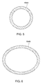
- the lower end portion 104A can have a circular section as shown in FIG. 5
- the upper end portion 104B can have an elliptical section as shown in FIG. 6
- the swing arm 104 can have a varying section that progressively enlarges from the circular section of the lower end portion 104A to the elliptical section of the upper end portion 104B.
- the construction using a tapered shape and varying section can allow the swing arm 104 to have greater strength for torsional loading, and can reduce deflection of the overall frame structure.
- a hub housing 122 can be affixed with the upper end portion 104B of the swing arm 104.
- the hub housing 122 can have a front formed with a recess 125 to define a carry handle 129 for facilitating the portability of the infant swing apparatus 100.
- the front of the hub housing 122 can also be assembled with a lamp 128 that is arranged adjacent to the carry handle 129. The lamp 128 can cast a gentle and ambient light over the child placed on the seat support 108.
- a top portion of the support column 112 can be assembled with a housing portion 130 that can enclose a motorized driving mechanism 132.
- the hub housing 122 and the upper end portion 104B of the swing arm 104 can be pivotally assembled with the top portion of the support column 112, and can be coupled with the driving mechanism 132.
- a control interface 133 comprised of multiple buttons may be arranged on the housing portion 130 for controlling the operation of the driving mechanism 132. Accordingly, the driving mechanism 132 can be operable to cause rotational displacement of the swing arm 104 about the pivot axis R so as to impart a pendulum motion to the seat support 108.
- the pivot axis R of the swing arm 104 can be inclined at an angle K relative to a horizontal axis, and can slope downward toward the rear 112R of the support column 112 and upward toward the front 112F of the support column 112.
- the angle K can be between about 5 and 30 degrees, e.g., 15 degrees.
- the angle K can also be substantially equal to the angle I between the upper portion 112B of the support column 112 and the vertical axis Z.
- This inclination of the pivot axis R can lower the frequency of the swing arm 104 compared to a horizontal pivot axis. Accordingly, the length of the swing arm 104 may be shortened for a more compact volume of the infant swing apparatus 100 without increasing the swing frequency.
- certain embodiments may provide an infant swing apparatus in which the pivot axis R of the swing arm 104 is inclined whereas the support column 112 extends substantially vertical. While the inclination of the pivot axis R may provide certain advantages as described previously, other embodiments of the infant swing apparatus 100 may also be implemented with the support column 112 leaning rearward whereas the pivot axis R is horizontal and parallel to a floor.
- a toy holding bar 136 may be removably assembled with the swing arm 104 adjacent to the hub housing 122.
- the toy holding bar 136 may be pivotally connected with a C-shaped clip 138 that can detachably fasten with the swing arm 104.
- the toy holding bar 136 can be pushed aside or completely removed for better access to the seat support 108.
- the seat support 108 can include a lower part 108A connected with the swing arm 104, and an upper part 108B for receiving a child.
- the lower part 108A of the seat support 108 can be affixed with the lower end portion 104A of the swing arm 104, and the upper part 108B can be pivotally assembled with the lower part 108A. Accordingly, the upper part 108B can rotate about a vertical axis relative to the lower part 108A to adjust the orientation of the seat support 108.
- the upper part 108B of the seat support 108 can include, for example, a U-shaped support arm 140, and a seat frame 142 of an elliptical shape pivotally connected with the support arm 140 via hinges 144.
- the seat frame 142 can be rotated about a horizontal pivot axis relative to the support arm 140 to recline the seat frame 142.
- a vibration unit 148 may also be installed on the seat frame 142 for imparting vibration to the seat support 108.
- FIGS. 7 and 8 are schematic views illustrating exemplary pendulum motion performed by the infant swing apparatus 100.
- the swing arm 104 can swing to a left and a right side of the support column 112 to impart a pendulum motion to the seat support 108.
- the toy holding bar 136 can move along with the oscillating swing arm 104.
- This pendulum motion can swing the seat support 108 sideways (as shown in FIGS. 7 and 8 ) or back and forth (not shown) depending on the orientation of the seat support 108.
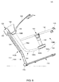
- FIG. 9 is a schematic view illustrating exemplary operation for transporting the infant swing apparatus 100.
- a caregiver can grasp the carry handle 129 to incline the infant swing apparatus 100 toward the rear 112R so that the wheel assemblies 118 are in effective rolling contact against the floor.
- the infant swing apparatus 100 then can be dragged or pushed with little effort.
- the caregiver may also grasp the carry handle 129 to lift the infant swing apparatus 100 above the floor, and then transport it without contact of the base frame 110 with the floor.
- Advantages of the structures described herein include the ability to provide an infant swing apparatus that is more compact in size, have better portability and is easy to use.
Landscapes
- Carriages For Children, Sleds, And Other Hand-Operated Vehicles (AREA)
- Toys (AREA)
Abstract
Description
- The present invention relates to infant swing apparatuses.
- Swing apparatuses can be used by parents to help calming or entertaining a child. An infant swing apparatus typically has a large base, and a swing arm that can travel in a pendulum motion. Unfortunately, most swing apparatuses currently available on the market occupy a significant space. Owing to a large size, they are not convenient to move from one room to another in a house.
- Therefore, there is a need for an infant swing apparatus that can be more compact, is easy to operate, and address at least the foregoing issues.
- The present application describes an infant swing apparatus. In one embodiment, the infant swing apparatus includes a base frame, a rigid support column rising from the base frame and having a front and a rear, and a swing arm arranged at the front of the support column and having a first end portion and a second end portion. The first end portion of the swing arm is connected with a seat support, and the second end portion of the swing arm is pivotally connected with the support column about a pivot axis that is located above the seat support, the swing arm having a tapered shape between the first and second end portions.
-
-
FIG. 1 is a perspective view illustrating an embodiment of an infant swing apparatus; -
FIG. 2 is a side view of the infant swing apparatus shown inFIG. 1 ; -
FIG. 3 is a top view of the infant swing apparatus shown inFIG. 1 ; -
FIG. 4 is a schematic view illustrating the assembly of a motorized driving mechanism in the infant swing apparatus; -
FIG. 5 is a cross-sectional view illustrating the section of a first end portion of a swing arm in the infant swing apparatus; -
FIG. 6 is a cross-sectional view illustrating the section of a second end portion of the swing arm in the infant swing apparatus; -
FIGS. 7 and8 are schematic views illustrating exemplary swing motion performed by the infant swing apparatus; and -
FIG. 9 is a schematic view illustrating exemplary operation for transporting the infant swing apparatus. -
FIG. 1 is a schematic view illustrating an embodiment of aninfant swing apparatus 100,FIG. 2 is a side view of theinfant swing apparatus 100, andFIG. 3 is a top view of theinfant swing apparatus 100. Theinfant swing apparatus 100 can include asupport frame 102, aswing arm 104 and aseat support 108. Thesupport frame 102 can include abase frame 110 extending along a horizontal plane, and arigid support column 112 rising upward from thebase frame 110 and having afront 112F and a rear 112R. Theswing arm 104 can be pivotally connected with thesupport column 112 at thefront 112F thereof and hold theseat support 108 above thebase frame 110. - The
base frame 110 can be formed by the assembly of one or more tube segments, and can form an enlarged loop that defines a support plane P. In one embodiment, thebase frame 110 can have arear edge 110A, afront edge 110B, and a left and aright side segment 110C respectively connected with the rear andfront edges rear edge 110A can be longer than thefront edge 110B, and the left andright side segments 110C can respectively converge from therear edge 110A toward thefront edge 110B. The enlarged area of thebase frame 110 can provide stable resting support on a floor and below theseat support 108. Moreover, therear edge 110A of thebase frame 110 can be assembled withmultiple wheel assemblies 118 that may facilitate transportation of theinfant swing apparatus 100. - It will be appreciated that the illustrated shape of the
base frame 110 is only one possible example, and other shapes may be implemented. - The
support column 112 can have alower portion 112A and anupper portion 112B connected with each other. In one embodiment, the lower andupper portions tube segments base frame 110. Ahousing 124 can enclose an upper region of the two assemblies oftube segments upper portion 112B of thesupport column 112. - The
lower portion 112A can be downwardly affixed with thebase frame 110, and can be connected upwardly with theupper portion 112B. Thelower portion 112A can have an elongated and substantially straight shape, and can extend vertically and perpendicular to the support plane P of thebase frame 110. - The
upper portion 112B can be downwardly connected with thelower portion 112A, and can be upwardly assembled with theswing arm 104 about a pivot axis R located above theseat support 108. Theupper portion 112B can have an elongated and substantially straight shape extending along an axis C, and can lean toward the rear 112R of thesupport column 112. The inclination angle I at which theupper portion 112B of thesupport column 112 is tilted relative to a vertical axis Z can be between about 5 and 30 degrees. Preferably, the inclination angle I can be around 15 degrees. The inclination angle I can be such that a projection of theupper portion 112B on the support plane P of thebase frame 110 can extend rearward past the rear edge 1 l0A of thebase frame 110. - The rearward inclination of the
support column 112 can displace a weight load distribution toward a vertical axis of support defined by thelower portion 112A. As a result, compared to a support column that rises uniformly vertical, the rearward inclination of thesupport column 112 can allow to reduce the size of thebase frame 110. For example, as shown inFIGS. 2 and3 , thebase frame 110 can be reduced such that a front portion of theseat support 108 when projected on the support plane P can extend forward past thefront edge 110B of thebase frame 110. - Referring again to
FIGS. 1-3 , theswing arm 104 can be arranged at thefront 112F of thesupport column 112, and can be formed as an assembly of tube segments. More specifically, theswing arm 104 can have alower end portion 104A connected with theseat support 108, anupper end portion 104B pivotally connected with the a top portion of thesupport column 112, and twosegments upper end portions segment 104C can extend substantially horizontal, and can be affixed with theseat support 108 at thelower end portion 104A. Thesegment 104D can have an elongated shape, and can rise upward from thesegment 104C along anaxis 126 that is substantially parallel to theupper portion 112B of the support column 112 (in particular, theaxis 126 of thesegment 104D of theswing arm 104 can be substantially parallel to the axis C of theupper portion 112B of the support column 112). The angle A between theaxis 126 of thesegment 104D and the vertical axis Z can be substantially equal to the inclination angle I of theupper portion 112B. - In one embodiment, the
swing arm 104 can have a tapered shape that progressively enlarges along the length of theswing arm 104 from thelower end portion 104A to theupper end portion 104B. For example, thelower end portion 104A can have a circular section as shown inFIG. 5 , theupper end portion 104B can have an elliptical section as shown inFIG. 6 , and theswing arm 104 can have a varying section that progressively enlarges from the circular section of thelower end portion 104A to the elliptical section of theupper end portion 104B. The construction using a tapered shape and varying section can allow theswing arm 104 to have greater strength for torsional loading, and can reduce deflection of the overall frame structure. - A
hub housing 122 can be affixed with theupper end portion 104B of theswing arm 104. Thehub housing 122 can have a front formed with arecess 125 to define acarry handle 129 for facilitating the portability of theinfant swing apparatus 100. Moreover, the front of thehub housing 122 can also be assembled with alamp 128 that is arranged adjacent to thecarry handle 129. Thelamp 128 can cast a gentle and ambient light over the child placed on theseat support 108. - Referring to
FIG. 4 , a top portion of thesupport column 112 can be assembled with ahousing portion 130 that can enclose a motorizeddriving mechanism 132. The hub housing 122 and theupper end portion 104B of theswing arm 104 can be pivotally assembled with the top portion of thesupport column 112, and can be coupled with thedriving mechanism 132. Acontrol interface 133 comprised of multiple buttons may be arranged on thehousing portion 130 for controlling the operation of thedriving mechanism 132. Accordingly, thedriving mechanism 132 can be operable to cause rotational displacement of theswing arm 104 about the pivot axis R so as to impart a pendulum motion to theseat support 108. - In one embodiment, the pivot axis R of the
swing arm 104 can be inclined at an angle K relative to a horizontal axis, and can slope downward toward the rear 112R of thesupport column 112 and upward toward thefront 112F of thesupport column 112. The angle K can be between about 5 and 30 degrees, e.g., 15 degrees. In one embodiment, the angle K can also be substantially equal to the angle I between theupper portion 112B of thesupport column 112 and the vertical axis Z. This inclination of the pivot axis R can lower the frequency of theswing arm 104 compared to a horizontal pivot axis. Accordingly, the length of theswing arm 104 may be shortened for a more compact volume of theinfant swing apparatus 100 without increasing the swing frequency. - It will be appreciated that certain embodiments may provide an infant swing apparatus in which the pivot axis R of the
swing arm 104 is inclined whereas thesupport column 112 extends substantially vertical. While the inclination of the pivot axis R may provide certain advantages as described previously, other embodiments of theinfant swing apparatus 100 may also be implemented with thesupport column 112 leaning rearward whereas the pivot axis R is horizontal and parallel to a floor. - Referring again to
FIGS. 1-4 , atoy holding bar 136 may be removably assembled with theswing arm 104 adjacent to thehub housing 122. Thetoy holding bar 136 may be pivotally connected with a C-shapedclip 138 that can detachably fasten with theswing arm 104. Thetoy holding bar 136 can be pushed aside or completely removed for better access to theseat support 108. - The
seat support 108 can include alower part 108A connected with theswing arm 104, and anupper part 108B for receiving a child. Thelower part 108A of theseat support 108 can be affixed with thelower end portion 104A of theswing arm 104, and theupper part 108B can be pivotally assembled with thelower part 108A. Accordingly, theupper part 108B can rotate about a vertical axis relative to thelower part 108A to adjust the orientation of theseat support 108. - In one embodiment, the
upper part 108B of theseat support 108 can include, for example, aU-shaped support arm 140, and aseat frame 142 of an elliptical shape pivotally connected with thesupport arm 140 via hinges 144. Theseat frame 142 can be rotated about a horizontal pivot axis relative to thesupport arm 140 to recline theseat frame 142. Avibration unit 148 may also be installed on theseat frame 142 for imparting vibration to theseat support 108. -
FIGS. 7 and8 are schematic views illustrating exemplary pendulum motion performed by theinfant swing apparatus 100. Theswing arm 104 can swing to a left and a right side of thesupport column 112 to impart a pendulum motion to theseat support 108. Thetoy holding bar 136 can move along with theoscillating swing arm 104. This pendulum motion can swing theseat support 108 sideways (as shown inFIGS. 7 and8 ) or back and forth (not shown) depending on the orientation of theseat support 108. - In conjunction with
FIG. 1 ,FIG. 9 is a schematic view illustrating exemplary operation for transporting theinfant swing apparatus 100. A caregiver can grasp thecarry handle 129 to incline theinfant swing apparatus 100 toward the rear 112R so that thewheel assemblies 118 are in effective rolling contact against the floor. Theinfant swing apparatus 100 then can be dragged or pushed with little effort. - Alternatively, the caregiver may also grasp the
carry handle 129 to lift theinfant swing apparatus 100 above the floor, and then transport it without contact of thebase frame 110 with the floor. - Advantages of the structures described herein include the ability to provide an infant swing apparatus that is more compact in size, have better portability and is easy to use.
- Realizations of the infant swing apparatus have been described in the context of particular embodiments. These embodiments are meant to be illustrative and not limiting. Many variations, modifications, additions, and improvements are possible. These and other variations, modifications, additions, and improvements may fall within the scope of the inventions as defined in the claims that follow.
Claims (14)
- An infant swing apparatus (100) comprising:a base frame (110);a support column (112) rising upward from the base frame (110), the support column (112) having a front (112F) and a rear (112R); anda swing arm (104) arranged at the front (112F) of the support column (112) and having a first end portion (104A) and a second end portion (104B), the first end portion (104A) being connected with a seat support (108), the second end portion (104B) being pivotally connected with the support column (112) about a pivot axis (R) that is located above the seat support (108), and the swing arm (104) having a tapered shape between the first and second end portions (104A, 104B).
- The infant swing apparatus (100) according to claim 1, wherein the swing arm (104) has a varying section that enlarges toward the second end portion (104B).
- The infant swing apparatus (100) according to claim 1 or 2, wherein the first end portion (104A) of the swing arm (104) has a circular section, and the second end portion (104B) of the swing arm (104) has an elliptical section.
- The infant swing apparatus (100) according to claim 1, 2 or 3, wherein the swing arm (104) further has a first and a second segment (104C, 104D) that are connected with each other and extend between the first and second end portions (104A, 104B), the first segment (104C) extending substantially horizontally and affixed with the seat support (108) at the first end portion (104A), and the second segment (104D) rising upward from the first segment (104C) and leaning rearward.
- The infant swing apparatus (100) according to any preceding claims, wherein the swing arm (104) is pivotally connected with an upper portion (112B) of the support column (112), the upper portion (112B) of the support column (112) leaning rearward.
- The infant swing apparatus (100) according to claim 5, wherein the base frame (110) has a rear edge (110A), and the upper portion (112B) of the support column (112) extends rearward past the rear edge (110A) of the base frame (110).
- The infant swing apparatus (100) according to claim 6, wherein the rear edge (110A) of the base frame (110) has a plurality of wheel assemblies (118), and the infant swing apparatus (100) is inclinable toward the rear (112R) of the support column (112) to cause the wheel assemblies (118) to be in rolling contact with a floor surface.
- The infant swing apparatus (100) according to claim 5, 6 or 7, wherein the support column (112) further includes a lower portion (112A) connected with the upper portion (112B), the lower portion (112A) extending substantially perpendicular to a support plane (P) defined by the base frame (110).
- The infant swing apparatus (100) according to any preceding claims, wherein the base frame (110) further has a front edge (110B), and a portion of the seat support (108) extends forward past the front edge (110B) of the base frame (110).
- The infant swing apparatus (100) according to any preceding claims, wherein the pivot axis (R) of the swing arm (104) slopes downward toward the rear (112R) of the support column (112).
- The infant swing apparatus (100) according to claim 10, wherein an angle (K) between the pivot axis (R) and a horizontal axis is substantially equal to an inclined angle (I) of an upper portion (112B) of the support column (112) relative to a vertical axis (Z).
- The infant swing apparatus (100) according to any preceding claims, further including a driving mechanism (132) operable to cause rotational displacement of the swing arm (104) about the pivot axis (R), the driving mechanism (132) being assembled with the support column (112).
- The infant swing apparatus (100) according to any preceding claims, wherein the second end portion (104B) of the swing arm (104) is affixed with a hub housing (122), and the hub housing (122) includes a carry handle (129).
- The infant swing apparatus (100) according to claim 13, wherein the hub housing (122) is further assembled with a lamp (128) arranged adjacent to the carry handle (129).
Applications Claiming Priority (3)
| Application Number | Priority Date | Filing Date | Title |
|---|---|---|---|
| US201361852784P | 2013-03-21 | 2013-03-21 | |
| US201361855317P | 2013-05-13 | 2013-05-13 | |
| EP14160882.8A EP2781173B1 (en) | 2013-03-21 | 2014-03-20 | Infant swing apparatus |
Related Parent Applications (2)
| Application Number | Title | Priority Date | Filing Date |
|---|---|---|---|
| EP14160882.8A Division EP2781173B1 (en) | 2013-03-21 | 2014-03-20 | Infant swing apparatus |
| EP14160882.8A Division-Into EP2781173B1 (en) | 2013-03-21 | 2014-03-20 | Infant swing apparatus |
Publications (2)
| Publication Number | Publication Date |
|---|---|
| EP3092920A1 true EP3092920A1 (en) | 2016-11-16 |
| EP3092920B1 EP3092920B1 (en) | 2018-03-14 |
Family
ID=50336164
Family Applications (2)
| Application Number | Title | Priority Date | Filing Date |
|---|---|---|---|
| EP14160882.8A Active EP2781173B1 (en) | 2013-03-21 | 2014-03-20 | Infant swing apparatus |
| EP16176693.6A Active EP3092920B1 (en) | 2013-03-21 | 2014-03-20 | Infant swing apparatus |
Family Applications Before (1)
| Application Number | Title | Priority Date | Filing Date |
|---|---|---|---|
| EP14160882.8A Active EP2781173B1 (en) | 2013-03-21 | 2014-03-20 | Infant swing apparatus |
Country Status (6)
| Country | Link |
|---|---|
| US (1) | US9173503B2 (en) |
| EP (2) | EP2781173B1 (en) |
| CN (1) | CN104055356B (en) |
| AU (1) | AU2014201661B2 (en) |
| ES (2) | ES2666225T3 (en) |
| TW (1) | TWI522072B (en) |
Families Citing this family (29)
| Publication number | Priority date | Publication date | Assignee | Title |
|---|---|---|---|---|
| KR101233026B1 (en) * | 2010-10-22 | 2013-02-20 | 주식회사 싸이버메딕 | Dynamic posture balance training system |
| CN203314544U (en) * | 2013-06-13 | 2013-12-04 | 中山市隆成日用制品有限公司 | Baby rocking chair skeleton capable of reducing width |
| US9433304B2 (en) * | 2014-03-07 | 2016-09-06 | Wonderland Nurserygoods Company Ltd. | Child motion apparatus |
| US9861210B2 (en) | 2015-09-09 | 2018-01-09 | Kids Ii, Inc. | Dual arm child motion device |
| US20160066708A1 (en) * | 2014-09-09 | 2016-03-10 | Kids Ii, Inc. | Wave-motion infant seat |
| US10045635B2 (en) * | 2015-05-26 | 2018-08-14 | Wonderland Switzerland Ag | Child motion apparatus |
| US9750350B2 (en) * | 2015-11-24 | 2017-09-05 | Mattel, Inc. | Bouncing and swiveling infant support structure |
| US10470576B2 (en) * | 2016-05-04 | 2019-11-12 | Aaron DeJule | Movable human support structure |
| US12167796B2 (en) | 2016-05-04 | 2024-12-17 | Aaron DeJule | Human support structure |
| USD859861S1 (en) * | 2017-09-12 | 2019-09-17 | Kids Ii, Inc. | Swing |
| US11439251B2 (en) * | 2017-09-22 | 2022-09-13 | Rohan Patel | Baby sleeping apparatus |
| CN108324013A (en) * | 2018-02-02 | 2018-07-27 | 浙江工业大学 | Intelligent cradle of individualized simulation mother's arms |
| EP3536193A1 (en) * | 2018-03-05 | 2019-09-11 | Ruoey Lung Enterprise Corp. | Base seat for bed or chair |
| US10681993B2 (en) * | 2018-06-14 | 2020-06-16 | Wonderland Switzerland Ag | Swing seat |
| CN109691821B (en) * | 2019-01-07 | 2022-05-13 | 广东省拉迪达科技有限公司 | Swing for children |
| CN111938369A (en) * | 2019-05-17 | 2020-11-17 | 穆蒙蒙 | Infant carrier device and method of operation thereof |
| US11641952B2 (en) | 2019-06-21 | 2023-05-09 | Kids2, Inc. | Modular cradle |
| CN113133612B (en) * | 2020-01-18 | 2026-01-27 | 中山市童印儿童用品有限公司 | Rocking chair for children |
| TWI853679B (en) * | 2020-03-27 | 2024-08-21 | 瑞士商明門瑞士股份有限公司 | Swing apparatus with magnetic drive and control |
| USD977865S1 (en) | 2020-09-17 | 2023-02-14 | Kids2, Inc. | Modular cradle |
| USD979259S1 (en) | 2020-09-17 | 2023-02-28 | Kids2, Inc. | Modular swing |
| USD978545S1 (en) | 2020-09-17 | 2023-02-21 | Kids2, Inc. | Modular highchair |
| USD958897S1 (en) | 2020-09-17 | 2022-07-26 | Kids2, Inc. | Modular toy bar |
| USD1073386S1 (en) * | 2021-07-02 | 2025-05-06 | Wonderland Switzerland Ag | Infant swing |
| GB2613683B (en) | 2021-10-14 | 2024-06-12 | Wonderland Switzerland Ag | Rotatable toy bar and vibration device for child swing |
| CN116261994A (en) * | 2021-12-14 | 2023-06-16 | 明门(中国)幼童用品有限公司 | Swing chair with music soothing function |
| CN114468676B (en) * | 2022-02-18 | 2024-07-02 | 好孩子儿童用品有限公司 | Child carrying device |
| EP4499255A4 (en) * | 2022-03-29 | 2026-03-25 | Wonderland Switzerland Ag | UPWIND VIBRATION ARRANGEMENT AND METHOD FOR USE |
| AU2024343481A1 (en) * | 2023-09-22 | 2026-04-02 | Wonderland Switzerland Ag | Wind up swing assembly and method of use |
Citations (2)
| Publication number | Priority date | Publication date | Assignee | Title |
|---|---|---|---|---|
| US4805902A (en) * | 1987-06-30 | 1989-02-21 | Spalding & Evenflo Companies, Inc. | Inclined-axis pendulum swing |
| US20100201171A1 (en) * | 2005-11-03 | 2010-08-12 | Graco Children's Products Inc. | Child Motion Device |
Family Cites Families (18)
| Publication number | Priority date | Publication date | Assignee | Title |
|---|---|---|---|---|
| US4254990A (en) * | 1979-03-13 | 1981-03-10 | Kelley Eugene M | Stabilized oscillating chair |
| US5803817A (en) | 1996-08-15 | 1998-09-08 | Fisher-Price, Inc. | Infant swing |
| US20020052245A1 (en) | 2000-10-27 | 2002-05-02 | Regalo International | Open top swing |
| US6578212B2 (en) | 2001-11-21 | 2003-06-17 | Cosco Management, Inc. | Cradle |
| US6544128B1 (en) * | 2002-03-20 | 2003-04-08 | Chih-Huang Yang | Swing device with an automatic driving unit |
| US6908397B2 (en) | 2003-03-31 | 2005-06-21 | Mattel, Inc. | Infant support structure with an entertainment device |
| US7563170B2 (en) * | 2005-11-03 | 2009-07-21 | Graca Children's Products Inc. | Child motion device |
| US7614930B2 (en) * | 2005-11-03 | 2009-11-10 | Graco Children's Products Inc. | Inflatable child activity center |
| WO2007056684A2 (en) * | 2005-11-03 | 2007-05-18 | Graco Children's Products Inc. | Child motion device |
| US8070617B2 (en) * | 2007-03-13 | 2011-12-06 | Kolcraft Enterprises, Inc. | Child swing and jumper apparatus and methods of operating the same |
| US7748063B2 (en) * | 2007-11-15 | 2010-07-06 | Excellerate Enterprise Co., Ltd. | Baby soothing device |
| CN101889794A (en) * | 2009-05-19 | 2010-11-24 | 宝钜儿童用品香港股份有限公司 | Baby swing |
| CN101756561B (en) | 2010-01-11 | 2011-08-31 | 好孩子儿童用品有限公司 | Baby rocking chair |
| US8684856B2 (en) | 2010-03-17 | 2014-04-01 | Mattel, Inc. | Infant swing and glider device |
| WO2012037522A1 (en) * | 2010-09-16 | 2012-03-22 | Kids Ii, Inc. | Motion device for children |
| US8602903B2 (en) | 2011-04-12 | 2013-12-10 | Kids Ii, Inc. | Child support repositioning mechanism |
| CN102894731A (en) * | 2011-07-28 | 2013-01-30 | 儿童二代公司 | Children's motion device |
| CN203106466U (en) | 2013-01-07 | 2013-08-07 | 好孩子儿童用品有限公司 | Swing swinging mechanism and baby swing |
-
2014
- 2014-03-19 AU AU2014201661A patent/AU2014201661B2/en active Active
- 2014-03-20 TW TW103110518A patent/TWI522072B/en active
- 2014-03-20 ES ES16176693.6T patent/ES2666225T3/en active Active
- 2014-03-20 US US14/220,610 patent/US9173503B2/en active Active
- 2014-03-20 EP EP14160882.8A patent/EP2781173B1/en active Active
- 2014-03-20 EP EP16176693.6A patent/EP3092920B1/en active Active
- 2014-03-20 ES ES14160882.8T patent/ES2636256T3/en active Active
- 2014-03-20 CN CN201410104157.9A patent/CN104055356B/en active Active
Patent Citations (2)
| Publication number | Priority date | Publication date | Assignee | Title |
|---|---|---|---|---|
| US4805902A (en) * | 1987-06-30 | 1989-02-21 | Spalding & Evenflo Companies, Inc. | Inclined-axis pendulum swing |
| US20100201171A1 (en) * | 2005-11-03 | 2010-08-12 | Graco Children's Products Inc. | Child Motion Device |
Also Published As
| Publication number | Publication date |
|---|---|
| AU2014201661B2 (en) | 2016-01-14 |
| CN104055356A (en) | 2014-09-24 |
| TWI522072B (en) | 2016-02-21 |
| EP3092920B1 (en) | 2018-03-14 |
| US20140287846A1 (en) | 2014-09-25 |
| ES2636256T3 (en) | 2017-10-05 |
| ES2666225T3 (en) | 2018-05-03 |
| CN104055356B (en) | 2016-08-17 |
| TW201436741A (en) | 2014-10-01 |
| EP2781173B1 (en) | 2017-05-03 |
| AU2014201661A1 (en) | 2014-10-09 |
| EP2781173A1 (en) | 2014-09-24 |
| US9173503B2 (en) | 2015-11-03 |
Similar Documents
| Publication | Publication Date | Title |
|---|---|---|
| EP3092920B1 (en) | Infant swing apparatus | |
| US9955799B2 (en) | Child motion device | |
| CN101299949B (en) | children's sports equipment | |
| CN105534136B (en) | Automatic lifting pillow | |
| US8070617B2 (en) | Child swing and jumper apparatus and methods of operating the same | |
| US8556779B2 (en) | Exercise device with gliding footlink pivot guide | |
| TW201318668A (en) | Running machine with workstation | |
| US7722118B2 (en) | Repositionable child support device | |
| CN104523059B (en) | Multifunctional supporting device for seat | |
| US20180098641A1 (en) | Convertible rocker | |
| CN204015741U (en) | Baby's bouncer and compact bouncer | |
| US20150231004A1 (en) | Wheelchair including a tiltable seat | |
| ES2581003T3 (en) | High chair | |
| CN113633524A (en) | An intelligent walker for preventing falls for the elderly | |
| CN204363461U (en) | Seat multifunctional supporter | |
| US20190075935A1 (en) | Bassinet with electromagnetic drive | |
| TWI707646B (en) | Base for bed, chair or sofa | |
| CN211380455U (en) | Base for bed, chair or sofa | |
| JP6006997B2 (en) | Veterinary training equipment | |
| US20220323293A1 (en) | Free-standing swinging and/or hanging seat for erotic purposes | |
| JPH0536425Y2 (en) | ||
| CN104000412B (en) | foldable rocking chair | |
| CN110558760A (en) | Chair assembly structure | |
| TWM435212U (en) | Inclination angle and feet-stop structure for swinging platform |
Legal Events
| Date | Code | Title | Description |
|---|---|---|---|
| PUAI | Public reference made under article 153(3) epc to a published international application that has entered the european phase |
Free format text: ORIGINAL CODE: 0009012 |
|
| 17P | Request for examination filed |
Effective date: 20160628 |
|
| AC | Divisional application: reference to earlier application |
Ref document number: 2781173 Country of ref document: EP Kind code of ref document: P |
|
| AK | Designated contracting states |
Kind code of ref document: A1 Designated state(s): AL AT BE BG CH CY CZ DE DK EE ES FI FR GB GR HR HU IE IS IT LI LT LU LV MC MK MT NL NO PL PT RO RS SE SI SK SM TR |
|
| RBV | Designated contracting states (corrected) |
Designated state(s): AL AT BE BG CH CY CZ DE DK EE ES FI FR GB GR HR HU IE IS IT LI LT LU LV MC MK MT NL NO PL PT RO RS SE SI SK SM TR |
|
| RAP1 | Party data changed (applicant data changed or rights of an application transferred) |
Owner name: WONDERLAND NURSERYGOODS COMPANY LIMITED |
|
| GRAP | Despatch of communication of intention to grant a patent |
Free format text: ORIGINAL CODE: EPIDOSNIGR1 |
|
| RIC1 | Information provided on ipc code assigned before grant |
Ipc: A47D 9/02 20060101AFI20170906BHEP |
|
| INTG | Intention to grant announced |
Effective date: 20170925 |
|
| RAP1 | Party data changed (applicant data changed or rights of an application transferred) |
Owner name: WONDERLAND SWITZERLAND AG |
|
| GRAS | Grant fee paid |
Free format text: ORIGINAL CODE: EPIDOSNIGR3 |
|
| GRAA | (expected) grant |
Free format text: ORIGINAL CODE: 0009210 |
|
| AC | Divisional application: reference to earlier application |
Ref document number: 2781173 Country of ref document: EP Kind code of ref document: P |
|
| AK | Designated contracting states |
Kind code of ref document: B1 Designated state(s): AL AT BE BG CH CY CZ DE DK EE ES FI FR GB GR HR HU IE IS IT LI LT LU LV MC MK MT NL NO PL PT RO RS SE SI SK SM TR |
|
| REG | Reference to a national code |
Ref country code: GB Ref legal event code: FG4D |
|
| REG | Reference to a national code |
Ref country code: CH Ref legal event code: EP Ref country code: CH Ref legal event code: NV Representative=s name: E. BLUM AND CO. AG PATENT- UND MARKENANWAELTE , CH Ref country code: AT Ref legal event code: REF Ref document number: 978025 Country of ref document: AT Kind code of ref document: T Effective date: 20180315 |
|
| REG | Reference to a national code |
Ref country code: IE Ref legal event code: FG4D |
|
| REG | Reference to a national code |
Ref country code: DE Ref legal event code: R096 Ref document number: 602014022477 Country of ref document: DE |
|
| REG | Reference to a national code |
Ref country code: FR Ref legal event code: PLFP Year of fee payment: 5 |
|
| REG | Reference to a national code |
Ref country code: ES Ref legal event code: FG2A Ref document number: 2666225 Country of ref document: ES Kind code of ref document: T3 Effective date: 20180503 |
|
| REG | Reference to a national code |
Ref country code: NL Ref legal event code: FP |
|
| REG | Reference to a national code |
Ref country code: LT Ref legal event code: MG4D |
|
| PG25 | Lapsed in a contracting state [announced via postgrant information from national office to epo] |
Ref country code: HR Free format text: LAPSE BECAUSE OF FAILURE TO SUBMIT A TRANSLATION OF THE DESCRIPTION OR TO PAY THE FEE WITHIN THE PRESCRIBED TIME-LIMIT Effective date: 20180314 Ref country code: LT Free format text: LAPSE BECAUSE OF FAILURE TO SUBMIT A TRANSLATION OF THE DESCRIPTION OR TO PAY THE FEE WITHIN THE PRESCRIBED TIME-LIMIT Effective date: 20180314 Ref country code: CY Free format text: LAPSE BECAUSE OF FAILURE TO SUBMIT A TRANSLATION OF THE DESCRIPTION OR TO PAY THE FEE WITHIN THE PRESCRIBED TIME-LIMIT Effective date: 20180314 Ref country code: FI Free format text: LAPSE BECAUSE OF FAILURE TO SUBMIT A TRANSLATION OF THE DESCRIPTION OR TO PAY THE FEE WITHIN THE PRESCRIBED TIME-LIMIT Effective date: 20180314 Ref country code: NO Free format text: LAPSE BECAUSE OF FAILURE TO SUBMIT A TRANSLATION OF THE DESCRIPTION OR TO PAY THE FEE WITHIN THE PRESCRIBED TIME-LIMIT Effective date: 20180614 |
|
| REG | Reference to a national code |
Ref country code: AT Ref legal event code: MK05 Ref document number: 978025 Country of ref document: AT Kind code of ref document: T Effective date: 20180314 |
|
| PG25 | Lapsed in a contracting state [announced via postgrant information from national office to epo] |
Ref country code: RS Free format text: LAPSE BECAUSE OF FAILURE TO SUBMIT A TRANSLATION OF THE DESCRIPTION OR TO PAY THE FEE WITHIN THE PRESCRIBED TIME-LIMIT Effective date: 20180314 Ref country code: BG Free format text: LAPSE BECAUSE OF FAILURE TO SUBMIT A TRANSLATION OF THE DESCRIPTION OR TO PAY THE FEE WITHIN THE PRESCRIBED TIME-LIMIT Effective date: 20180614 Ref country code: GR Free format text: LAPSE BECAUSE OF FAILURE TO SUBMIT A TRANSLATION OF THE DESCRIPTION OR TO PAY THE FEE WITHIN THE PRESCRIBED TIME-LIMIT Effective date: 20180615 Ref country code: SE Free format text: LAPSE BECAUSE OF FAILURE TO SUBMIT A TRANSLATION OF THE DESCRIPTION OR TO PAY THE FEE WITHIN THE PRESCRIBED TIME-LIMIT Effective date: 20180314 Ref country code: LV Free format text: LAPSE BECAUSE OF FAILURE TO SUBMIT A TRANSLATION OF THE DESCRIPTION OR TO PAY THE FEE WITHIN THE PRESCRIBED TIME-LIMIT Effective date: 20180314 |
|
| PG25 | Lapsed in a contracting state [announced via postgrant information from national office to epo] |
Ref country code: AL Free format text: LAPSE BECAUSE OF FAILURE TO SUBMIT A TRANSLATION OF THE DESCRIPTION OR TO PAY THE FEE WITHIN THE PRESCRIBED TIME-LIMIT Effective date: 20180314 Ref country code: PL Free format text: LAPSE BECAUSE OF FAILURE TO SUBMIT A TRANSLATION OF THE DESCRIPTION OR TO PAY THE FEE WITHIN THE PRESCRIBED TIME-LIMIT Effective date: 20180314 Ref country code: EE Free format text: LAPSE BECAUSE OF FAILURE TO SUBMIT A TRANSLATION OF THE DESCRIPTION OR TO PAY THE FEE WITHIN THE PRESCRIBED TIME-LIMIT Effective date: 20180314 Ref country code: RO Free format text: LAPSE BECAUSE OF FAILURE TO SUBMIT A TRANSLATION OF THE DESCRIPTION OR TO PAY THE FEE WITHIN THE PRESCRIBED TIME-LIMIT Effective date: 20180314 |
|
| PG25 | Lapsed in a contracting state [announced via postgrant information from national office to epo] |
Ref country code: SK Free format text: LAPSE BECAUSE OF FAILURE TO SUBMIT A TRANSLATION OF THE DESCRIPTION OR TO PAY THE FEE WITHIN THE PRESCRIBED TIME-LIMIT Effective date: 20180314 Ref country code: AT Free format text: LAPSE BECAUSE OF FAILURE TO SUBMIT A TRANSLATION OF THE DESCRIPTION OR TO PAY THE FEE WITHIN THE PRESCRIBED TIME-LIMIT Effective date: 20180314 Ref country code: SM Free format text: LAPSE BECAUSE OF FAILURE TO SUBMIT A TRANSLATION OF THE DESCRIPTION OR TO PAY THE FEE WITHIN THE PRESCRIBED TIME-LIMIT Effective date: 20180314 Ref country code: CZ Free format text: LAPSE BECAUSE OF FAILURE TO SUBMIT A TRANSLATION OF THE DESCRIPTION OR TO PAY THE FEE WITHIN THE PRESCRIBED TIME-LIMIT Effective date: 20180314 |
|
| REG | Reference to a national code |
Ref country code: BE Ref legal event code: MM Effective date: 20180331 |
|
| REG | Reference to a national code |
Ref country code: DE Ref legal event code: R097 Ref document number: 602014022477 Country of ref document: DE |
|
| REG | Reference to a national code |
Ref country code: IE Ref legal event code: MM4A |
|
| PG25 | Lapsed in a contracting state [announced via postgrant information from national office to epo] |
Ref country code: LU Free format text: LAPSE BECAUSE OF NON-PAYMENT OF DUE FEES Effective date: 20180320 Ref country code: PT Free format text: LAPSE BECAUSE OF FAILURE TO SUBMIT A TRANSLATION OF THE DESCRIPTION OR TO PAY THE FEE WITHIN THE PRESCRIBED TIME-LIMIT Effective date: 20180716 |
|
| PLBE | No opposition filed within time limit |
Free format text: ORIGINAL CODE: 0009261 |
|
| STAA | Information on the status of an ep patent application or granted ep patent |
Free format text: STATUS: NO OPPOSITION FILED WITHIN TIME LIMIT |
|
| PG25 | Lapsed in a contracting state [announced via postgrant information from national office to epo] |
Ref country code: MC Free format text: LAPSE BECAUSE OF FAILURE TO SUBMIT A TRANSLATION OF THE DESCRIPTION OR TO PAY THE FEE WITHIN THE PRESCRIBED TIME-LIMIT Effective date: 20180314 Ref country code: DK Free format text: LAPSE BECAUSE OF FAILURE TO SUBMIT A TRANSLATION OF THE DESCRIPTION OR TO PAY THE FEE WITHIN THE PRESCRIBED TIME-LIMIT Effective date: 20180314 Ref country code: IE Free format text: LAPSE BECAUSE OF NON-PAYMENT OF DUE FEES Effective date: 20180320 |
|
| 26N | No opposition filed |
Effective date: 20181217 |
|
| PG25 | Lapsed in a contracting state [announced via postgrant information from national office to epo] |
Ref country code: BE Free format text: LAPSE BECAUSE OF NON-PAYMENT OF DUE FEES Effective date: 20180331 Ref country code: SI Free format text: LAPSE BECAUSE OF FAILURE TO SUBMIT A TRANSLATION OF THE DESCRIPTION OR TO PAY THE FEE WITHIN THE PRESCRIBED TIME-LIMIT Effective date: 20180314 |
|
| PG25 | Lapsed in a contracting state [announced via postgrant information from national office to epo] |
Ref country code: MT Free format text: LAPSE BECAUSE OF NON-PAYMENT OF DUE FEES Effective date: 20180320 |
|
| PG25 | Lapsed in a contracting state [announced via postgrant information from national office to epo] |
Ref country code: MK Free format text: LAPSE BECAUSE OF NON-PAYMENT OF DUE FEES Effective date: 20180314 Ref country code: HU Free format text: LAPSE BECAUSE OF FAILURE TO SUBMIT A TRANSLATION OF THE DESCRIPTION OR TO PAY THE FEE WITHIN THE PRESCRIBED TIME-LIMIT; INVALID AB INITIO Effective date: 20140320 |
|
| PG25 | Lapsed in a contracting state [announced via postgrant information from national office to epo] |
Ref country code: IS Free format text: LAPSE BECAUSE OF FAILURE TO SUBMIT A TRANSLATION OF THE DESCRIPTION OR TO PAY THE FEE WITHIN THE PRESCRIBED TIME-LIMIT Effective date: 20180714 |
|
| P01 | Opt-out of the competence of the unified patent court (upc) registered |
Effective date: 20230522 |
|
| PGFP | Annual fee paid to national office [announced via postgrant information from national office to epo] |
Ref country code: ES Payment date: 20250423 Year of fee payment: 12 |
|
| PGFP | Annual fee paid to national office [announced via postgrant information from national office to epo] |
Ref country code: CH Payment date: 20250401 Year of fee payment: 12 |
|
| REG | Reference to a national code |
Ref country code: CH Ref legal event code: U11 Free format text: ST27 STATUS EVENT CODE: U-0-0-U10-U11 (AS PROVIDED BY THE NATIONAL OFFICE) Effective date: 20260401 |
|
| PGFP | Annual fee paid to national office [announced via postgrant information from national office to epo] |
Ref country code: GB Payment date: 20260306 Year of fee payment: 13 |
|
| PGFP | Annual fee paid to national office [announced via postgrant information from national office to epo] |
Ref country code: DE Payment date: 20260305 Year of fee payment: 13 |
|
| PGFP | Annual fee paid to national office [announced via postgrant information from national office to epo] |
Ref country code: IT Payment date: 20260320 Year of fee payment: 13 |
|
| PGFP | Annual fee paid to national office [announced via postgrant information from national office to epo] |
Ref country code: NL Payment date: 20260323 Year of fee payment: 13 |
|
| PGFP | Annual fee paid to national office [announced via postgrant information from national office to epo] |
Ref country code: FR Payment date: 20260306 Year of fee payment: 13 |
|
| PGFP | Annual fee paid to national office [announced via postgrant information from national office to epo] |
Ref country code: TR Payment date: 20260303 Year of fee payment: 13 |