EP3092893B1 - Root intrusion protection of subsurface drip irrigation pipe - Google Patents
Root intrusion protection of subsurface drip irrigation pipe Download PDFInfo
- Publication number
- EP3092893B1 EP3092893B1 EP16169556.4A EP16169556A EP3092893B1 EP 3092893 B1 EP3092893 B1 EP 3092893B1 EP 16169556 A EP16169556 A EP 16169556A EP 3092893 B1 EP3092893 B1 EP 3092893B1
- Authority
- EP
- European Patent Office
- Prior art keywords
- layer
- tube
- herbicide
- barrier layer
- drip irrigation
- Prior art date
- Legal status (The legal status is an assumption and is not a legal conclusion. Google has not performed a legal analysis and makes no representation as to the accuracy of the status listed.)
- Active
Links
Images


Classifications
-
- A—HUMAN NECESSITIES
- A01—AGRICULTURE; FORESTRY; ANIMAL HUSBANDRY; HUNTING; TRAPPING; FISHING
- A01G—HORTICULTURE; CULTIVATION OF VEGETABLES, FLOWERS, RICE, FRUIT, VINES, HOPS OR SEAWEED; FORESTRY; WATERING
- A01G25/00—Watering gardens, fields, sports grounds or the like
- A01G25/06—Watering arrangements making use of perforated pipe-lines located in the soil
-
- A—HUMAN NECESSITIES
- A01—AGRICULTURE; FORESTRY; ANIMAL HUSBANDRY; HUNTING; TRAPPING; FISHING
- A01M—CATCHING, TRAPPING OR SCARING OF ANIMALS; APPARATUS FOR THE DESTRUCTION OF NOXIOUS ANIMALS OR NOXIOUS PLANTS
- A01M21/00—Apparatus for the destruction of unwanted vegetation, e.g. weeds
-
- F—MECHANICAL ENGINEERING; LIGHTING; HEATING; WEAPONS; BLASTING
- F16—ENGINEERING ELEMENTS AND UNITS; GENERAL MEASURES FOR PRODUCING AND MAINTAINING EFFECTIVE FUNCTIONING OF MACHINES OR INSTALLATIONS; THERMAL INSULATION IN GENERAL
- F16L—PIPES; JOINTS OR FITTINGS FOR PIPES; SUPPORTS FOR PIPES, CABLES OR PROTECTIVE TUBING; MEANS FOR THERMAL INSULATION IN GENERAL
- F16L11/00—Hoses, i.e. flexible pipes
- F16L11/04—Hoses, i.e. flexible pipes made of rubber or flexible plastics
- F16L11/12—Hoses, i.e. flexible pipes made of rubber or flexible plastics with arrangements for particular purposes, e.g. specially profiled, with protecting layer, heated, electrically conducting
-
- Y—GENERAL TAGGING OF NEW TECHNOLOGICAL DEVELOPMENTS; GENERAL TAGGING OF CROSS-SECTIONAL TECHNOLOGIES SPANNING OVER SEVERAL SECTIONS OF THE IPC; TECHNICAL SUBJECTS COVERED BY FORMER USPC CROSS-REFERENCE ART COLLECTIONS [XRACs] AND DIGESTS
- Y02—TECHNOLOGIES OR APPLICATIONS FOR MITIGATION OR ADAPTATION AGAINST CLIMATE CHANGE
- Y02A—TECHNOLOGIES FOR ADAPTATION TO CLIMATE CHANGE
- Y02A40/00—Adaptation technologies in agriculture, forestry, livestock or agroalimentary production
- Y02A40/10—Adaptation technologies in agriculture, forestry, livestock or agroalimentary production in agriculture
- Y02A40/22—Improving land use; Improving water use or availability; Controlling erosion
Definitions
- the device can be made by co-extruding the beads 62 at twelve inch intervals in which the separate beads are approximately one inch long and extruded in the vicinity of the dripper exit holes 64. This can be done by a timer control on the extrusion die output to stop and start the bead extrusion process.
- the beads are bonded by hot meld adhesion to the tube material.
Landscapes
- Life Sciences & Earth Sciences (AREA)
- Engineering & Computer Science (AREA)
- Environmental Sciences (AREA)
- Soil Sciences (AREA)
- Water Supply & Treatment (AREA)
- General Engineering & Computer Science (AREA)
- Insects & Arthropods (AREA)
- Pest Control & Pesticides (AREA)
- Wood Science & Technology (AREA)
- Zoology (AREA)
- Mechanical Engineering (AREA)
- Catching Or Destruction (AREA)
- Agricultural Chemicals And Associated Chemicals (AREA)
- Rigid Pipes And Flexible Pipes (AREA)
Description
- This invention relates to slow-release materials and a process for controlling the diffusion rate at which a slow-release material diffuses from a substrate or a carrier, and more particularly, to drip irrigation devices having a controlled release rate of a herbicide that inhibits root growth by incorporating a layer of barrier material between the herbicide and the wall of the drip irrigation tube to reduce the movement of the herbicide through the wall of the pipe.
- Subsurface drip irrigation is a well-known irrigation technique with many advantages. A major problem with subsurface drip irrigation is root intrusion into the drip irrigation device such as tapes and pipes. Three techniques exist for preventing root intrusion and include periodic injection of a herbicide through the drip irrigation system, continuous addition of a herbicide to the irrigation water, and/or compounding a herbicide into the plastic material of the drip irrigation device to slowly release it into the soil around the dripper of the device.
WO0131999 WO9513882 - Dinitro-anilines are the herbicides most commonly used in these methods. Dinitro-anilines have very low solubility in water. While some of the herbicide is carried in the water in suspension through the dripper into the soil, a large proportion of the herbicide migrates through the wall of the drip irrigation pipe into the soil around the dripper and a lot of herbicide ends up too far from the emission points from the dripper that needs to be protected. The addition of dinitro-anilines to the dripper can also impair the adhesion of the dripper to the wall of the drip irrigation pipe or tube.
- The slow-release of dinitro-aniline from polymers to protect subsurface drip irrigation systems from root intrusion is well-known. In certain applications, dinitro-aniline is incorporated into the dripper itself. This technology works well with heavy walled tube and round drippers, however, does not work very well with thin-walled drip irrigation tubes or tape. Tapes are formed by various techniques with embossed or printed flow patterns. For tapes, there is no thick molded part or extruded sections into which one can conveniently incorporate the dinitro-aniline. For thin-walled tubes, small flat drippers which are stuck to the side of the wall have been developed and adhesion to the wall is reduced by the addition of dinitro-aniline. Because the release rate of dinitro-aniline is directly proportional to the surface area and inversely proportional to the thickness, it was difficult to achieve a long life cycle for thin-walled tubes and tapes incorporating dinitro-aniline.
- Many subsurface drip irrigation systems are protected from root intrusion by means of periodical or continuous injection of a herbicide into the irrigation water. In these cases, between irrigation cycles a large proportion of the herbicide is absorbed into the walls of the tube and from there into the soil far away from the outlet. And, during irrigation cycles, the outlets closest to the injection point receive more herbicide than those at the end of the system. The result is excessive application of the herbicide with both environmental risks and economic costs. In the case of compounding the herbicide into the drip irrigation device to create a herbicide impregnated tube, due to the large surface area a low concentration of the herbicide in the plastic of the tube will deliver enough herbicide to the water and then into the soil to prevent root intrusion. However, in this scenario herbicide will be lost by moving directly into the soil far away from the emission points where the protection against root intrusion is needed. Further, because the herbicide is infused throughout the wall of the tube, the diffusion through the wall and into the soil results in a short useful life of the product. Consequently, a need exists for an improved subsurface drip irrigation system to prevent root intrusion which addresses the drawbacks of existing systems.
- The present invention is a subsurface drip irrigation system comprising a drip irrigation tube which is extruded and having a herbicide compounded into the extruded tube. The tube includes a barrier layer on the outside of the tube to prevent movement of the herbicide directly into the soil. The herbicide migrates from the tube into the water and within the tube before exiting through the dripper into the soil. According to the invention, a bead containing the herbicide is extruded and (partially) buried into the wall of the tube. The herbicide is slowly released from the bead into the water which in turn passes through the dripper into the soil. The bead can be continuous or it can be in short lengths placed near to the dripper. A layer of barrier material may be placed between the bead and the wall to reduce movement of the herbicide into the wall. The barrier layer can be a complete or partial inner lining or the barrier material can be used as an outer lining of the entire tube. Incorporating a barrier wall for the tube also improves efficiency for embodiments where periodic injection of the herbicide into the water through the drip system or a continuous addition of a herbicide into the irrigation water are utilized.
- These and other aspects of the present invention will be more fully understood by reference to the following detailed description and accompanying drawings.
-
-
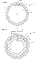
FIG. 1 is a cross-sectional view of a drip irrigation tape or tube having an internal flow path with a layer having a bioactive material comprising a herbicide within a polymeric material and an outer barrier layer; -
FIG. 2 is a cross-sectional view of a drip irrigation tape or tube similar toFIG. 1 including a bactericide layer positioned with the herbicide layer; -
FIG. 3 is a fragmentary cross-sectional perspective view illustrating a drip irrigation tape or tube having an internal flow path with a continuous bead of slow release herbicide-impregnated polymeric material extruded as a continuous bead alongside the flow path and a barrier layer; -
FIG. 4 is a fragmentary cross-sectional perspective view showing a drip irrigation tape or tube similar toFIG. 3 in which separate beads are located adjacent to the exit holes of a dripper flow path; -
FIG. 5 is a cross-section view showing a drip irrigation tape or tube in which the bead of herbicide-impregnated polymeric material is embedded within the wall of the tape or tube having barrier material; and -
FIG. 6 is a cross-sectional view of a drip irrigation tape or tube having an external emitter or dripper. -
FIG. 1 illustrates a cross-section of a drip irrigation tape ortube 10 not according to the present invention. The tape or tube is a thin-walled product. Such thin-walled tape or tube products are defined by wall thickness generally in the range of about 4 to about 50 mils. It is believed that it is most useful for a drip irrigation tape product to have a wall thickness in the range of about 4 to about 20 mils. A typical wall thickness of such tape products is about 8 mils, although tape products can have a wall thickness up to about 40 mils. It can be useful with thin-walled tubes generally to have a thickness of about 30 to about 50 mils. The tape or tube preferably is made of low density polyethylene.FIG. 1 illustrates a thin-walled tube 12 comprising aninner layer 14 and anouter layer 16. The inner layer is a polyethylene or polyolefin containing a herbicide and theouter layer 16 is a barrier layer preventing the herbicide from moving from the inner layer outwardly into soil in which thedrip irrigation device 10 is positioned during use. - Positioned on the
inside wall 18 of the inner layer is an emitter ordripper 20 having aninlet 22 for receipt of water through theflow path 24. The flow path extends continuously along the inside of thetube 12. The water entersinlet 22 in the emitter and out of the device throughoutlet 26 which extends through the inner andouter layers outlet 26 extending through the tube are similarly spaced at intervals along the tube. Theoutlets 26 supply water at a low drip rate and at predetermined spaced-apart intervals along an irrigation line. - As indicated, the
tube 12 is a two-layer extrusion wherein the inner layer is a polyolefin containing a herbicide that is slowly released into the water in theflow path 24 through known techniques. The herbicides most commonly used are dinitro-anilines such as trifluralin or pendimethalin. The outer layer is a barrier layer preventing the herbicide from moving from the inner layer directly into the soil. The outer layer can be any one of several barrier resins including but not limited to Saran, EVA, Nylon, PVDC, EVOH, Barex and compounds thereof with or without nano-clays or other additives to further improve the barrier properties. The barrier layer can also be a polyolefin compound containing a barrier material such as nano-clay or submicron silica or a powdered iron oxide of magnetite. Since the barrier layer prevents movement of the herbicide out through the inner layer, all of the herbicide will be carried by the water through the dripper into the soil exactly where it is needed to prevent root intrusion. In addition, the outside barrier layers can be selected to improve the physical properties of the drip irrigation device. -
FIG. 2 illustrates an alternativedrip irrigation device 30, not according to the invention, similar todrip irrigation device 10 with the addition of abactericide layer 32 combined with theinner layer 14 and including a dispersed bactericide for use in killing slime-producing bacteria. The bactericide layer and the inner layer are the same layer. -
FIG. 3 illustrates anotherdrip irrigation device 40 comprising amulti-layer tube 42 having aninner layer 44 and anouter layer 46. Theouter layer 46 is a standard flexible supply tube made of low-density polyethylene. Insidelayer 44 is a barrier layer comprising any one of several barrier resins identified earlier. Alternatively, the inner layer can be the standard flexible supply tube and the outer layer can be the barrier material layer. InFIG. 3 acontinuous bead 48 of a bioactive material extends continuously along the inside wall of the tube adjacent the emitter ordripper 50 within theflow path 52. Alternatively the bead can be positioned anywhere along the inside wall of the tube. -
FIG. 4 illustrates anotherdrip irrigation device 60 wherein thebead 62 of bioactive material is not continuous as inFIG. 3 , but rather is separate self-containedbeads 62 located adjacent exit holes 64 of the irrigation line. As a further alternative (not shown), the bead of bioactive material can be formed with a larger cross-section as shown inFIG. 2 and a thinner or reduced cross-section between the exit hole so that the largest surface area of the bead is present in the vicinities of the exit holes. - The bead of bioactive materials can be formed by incorporating the bioactive material into a suitable polymeric binder that can be extruded along the inside of the tube and bonded to the inside wall of the tube.
FIGs. 3 and 4 illustrate the bead extruded as anelongated cylinder 48 or as separatecylindrical shapes 62 essentially circular in cross-section. This configuration maximizes the surface area to volume ratio of the bead which has a beneficial effect on long-term diffusion rate during use. The bioactive material is a herbicide such as trifluralin, pendimethalin or other dinitro-aniline material, although other herbicides may be used. The herbicide is combined with a suitable carrier, such as carbon black, and impregnated uniformly throughout a polymeric binder material such as low-density polyethylene resin or other polyolefin resins. - Slow-release products such as certain herbicides which are incorporated into polymers such as polyethylene used as the encapsulation matrix are compounded by initially absorbing the herbicide into particles of carbon black. The carbon black is used because it is inert, in particulate form, and capable of absorbing and retaining within it the herbicide molecules similar to the absorption characteristics of a sponge. The carbon black and herbicide can be absorbed at a one-to-one ratio and then blended with a small amount of polyethylene resin in particulate form, and this blended material is later mixed into a standard polyethylene carrier material which can then be formed into the bead of bioactive material. As shown in
FIG. 4 , the device can be made by co-extruding thebeads 62 at twelve inch intervals in which the separate beads are approximately one inch long and extruded in the vicinity of the dripper exit holes 64. This can be done by a timer control on the extrusion die output to stop and start the bead extrusion process. The beads are bonded by hot meld adhesion to the tube material. - The bioactive material can also include dispersed nano-clay particles for reducing the diffusion rate of the slow-release bioactive material. The extruded bead of bioactive material could include such nano-clay particles as described in
U.S. Patent 6,821,928 . - The drip irrigation devices of
FIGS. 3 and 4 since they include a barrier layer, prevent the movement of the herbicide into the walls of the dripline so that all the herbicide will be carrier by the water through theinlet 54 into thedripper 50 and out the exit oroutlet hole 64 into the soil exactly where it is needed to prevent root intrusion. For applications where the barrier layer is on the outside of the tube herbicide can be added to both the bead and the inside layer which may be useful in circumstances where a very long life of the device is required. For example, the market for subsurface drip irrigation requires products designed to be used for a range of periods of time. Permanent crops such as vines or olives could require a 20+ year life. Crops like sugar cane and alfalfa are usually replanted about every 7 years. Tomatoes are replanted annually. Using the drip irrigation device of the present invention the device designer can engineer various thicknesses of the tube wall, concentration of the herbicide and the use of nano-clay to match the expected life of root intrusion protection with the crop and the cultural practices of the farmer. In applications which include a bead, the designer can also vary the diameter of the bead as well as the concentration of the herbicide. The decision to use the bead and/or the addition of the herbicide to the tube and/or the impermeable inner or outer lining will depend on the specifics of the particular application. - As indicated the barrier layer can include nano-clays which are nanometer sized clay particles that can be incorporated into the polymeric host carrier to assist in providing the barrier. The presence of the nano-clay particles reduces the porosity of the polymer or to assist in providing the barrier. For example, the barrier layer could contain 2% nano-clay. The specific type of nano-clay incorporated can be as disclosed in
U.S. Patent 6,821,928 . Other types of particles can also be utilized such as submicron silica or magnetite.FIG. 5 illustrates anotherdrip irrigation device 70, not according to the invention, wherein thebead 72 of bioactive material is embedded in theinner wall 74 of thetube 76. The tube includes a barrier layer of nano-clay particles or can be a multiple layer configuration as shown inFIGS. 1-4 . The emitter ordripper 78 is positioned over thebead 72 so that water carries the herbicide out theoutlet hole 80 into the surrounding soil after entering theinlet hole 82 in the dripper from theflowpath 84. Alternatively the dripper and outlet holes can be positioned at other locations on the tube. -
FIG. 6 illustrates anotherdrip irrigation device 90, not according to the invention, having atube 92 similar toFIG. 1 (however any of the tube configurations shown ifFIGS. 2-5 can be used) having an external emitter ordripper 94 which is attached to the tube through theoutlet hole 96 by having abarb 98 located at an end of apost 100.Post 100 extends through the tube so that thebarb 98 is positioned on the inside of the tube.Dripper 94 has aninlet hole 102 in the barb and anoutlet hole 104 on the opposite end. - Although the present invention has been disclosed with various embodiments, it is to be understood that changes and modifications can be made therein which are within the intended scope of the invention as hereinafter claimed.
Claims (14)
- A subsurface drip irrigation device (10) comprising:a tube (12) having a first layer (14) having a releasable herbicide compounded in the first layer (14), and a second barrier layer (16) adjacent the first layer (14);a plurality of outlets (26) extending through the tube (12) in a spaced relationship along a length of the tube (12); anda plurality of drippers (20) positioned on the inside surface (18) of the tube (12) in a spaced relationship such that a dripper (20) is positioned over an outlet (26),wherein the drippers (20) have an inlet (22) for receipt of water flowing through a flow path (24) within the tube (12), andwherein the second barrier layer (16) prevents outward movement of released herbicide from the first layer (14) directly through the first layer (14) into surrounding soil and directs the released herbicide into the flow path (24) for exiting the drip irrigation device (10) with the water through the drippers (20) and the outlets (26) in the tube (12) to prevent root intrusion into the device (10), the releasable herbicide being compounded into a bead (48, 62) positioned into an inside surface of the first layer (14).
- The device (10) of claim 1, wherein the releasable herbicide is compounded into the first layer (14) and the barrier layer (16) is positioned around the first layer (14).
- The device (10) of claim 1, wherein the barrier layer (16) is positioned around the first layer (14), and/or
wherein the barrier layer (16) is positioned on at least a portion of an inside surface of the first layer (14), and/or
wherein the bead (48) is formed as an elongated cylinder and is either a continuous uniform or non-uniform cylinder or separate beads. - The device (10) of claim one of claims 1 to 3, wherein the first layer (14) comprises a polyolefin, and/or
wherein the barrier layer (16) comprises a barrier resin selected from the group including Saran, EVA, Nylon, PVDC, EVOH or Barex,
wherein the barrier layer includes in particular nano-clay particles. - The device (10) of one of claims 1 to 4, wherein the barrier layer (16) is polyethylene having nano-clay, submicron silica or magnetite particles.
- The device (10) of one of claims 1 to 5, wherein the herbicide is a dinitro-aniline.
- The device (10) of one of claims 1 to 6, wherein the first layer (16) comprises a bactericide compounded therein.
- A method for delivering a herbicide contained within a subsurface drip irrigation device (10) comprising the steps of:providing a drip irrigation tube (12), having a first layer (14) having a releasable herbicide compounded in the first layer (14), a second barrier layer (16) adjacent the first layer (14), a plurality of outlets (26) extending through the tube (12) in a spaced relationship along the tube (12), a plurality of drippers (20) positioned on an inside surface (18) of the tube (12) in a spaced relationship over an outlet in the tube (12), the releasable herbicide being compounded into a bead (48, 62) positioned into an inside surface of the first layer (14);providing a stream of water through a flow path (24) in the tube (12);releasing the herbicide into the flow path (24);blocking the herbicide from movement through the tube (12) by the barrier layer (16); anddirecting the herbicide into an inlet in the dripper (20) and out the outlet (26).
- The method of claim 8, wherein the the second barrier layer (16) is positioned around an outside surface of the first layer (14).
- The method of claims 8 or 9, wherein wherein the second barrier layer (16) is positioned on an at least a portion of an inside surface of the first layer (14).
- The method of one of claims 8 to 10, wherein the first layer (14) comprises a polyolefin.
- The method of claim one of claims 8 to 11, wherein the second barrier layer (16) comprises a barrier resin selected from the group including Saran, EVA, Nylon, PVDC, EVOH or Barex,
wherein the second barrier layer (16) includes in particular nano-clay particles. - The method of one of claims 8 to 12, wherein the second barrier layer (16) is polyethylene having nano-clay, submicron silica or magnetite particles.
- The method of one of claims 8 to 13, further comprising releasing a bactericide compounded into the first layer (14) into the flow path.
Priority Applications (2)
| Application Number | Priority Date | Filing Date | Title |
|---|---|---|---|
| SI201630403T SI3092893T1 (en) | 2015-05-13 | 2016-05-13 | Root intrusion protection of subsurface drip irrigation pipe |
| PL16169556T PL3092893T3 (en) | 2015-05-13 | 2016-05-13 | Root intrusion protection of subsurface drip irrigation pipe |
Applications Claiming Priority (2)
| Application Number | Priority Date | Filing Date | Title |
|---|---|---|---|
| US201562161234P | 2015-05-13 | 2015-05-13 | |
| US15/143,359 US20160330918A1 (en) | 2015-05-13 | 2016-04-29 | Root intrusion protection of subsurface drip irrigation pipe |
Publications (2)
| Publication Number | Publication Date |
|---|---|
| EP3092893A1 EP3092893A1 (en) | 2016-11-16 |
| EP3092893B1 true EP3092893B1 (en) | 2019-07-10 |
Family
ID=56026663
Family Applications (1)
| Application Number | Title | Priority Date | Filing Date |
|---|---|---|---|
| EP16169556.4A Active EP3092893B1 (en) | 2015-05-13 | 2016-05-13 | Root intrusion protection of subsurface drip irrigation pipe |
Country Status (16)
| Country | Link |
|---|---|
| US (1) | US20160330918A1 (en) |
| EP (1) | EP3092893B1 (en) |
| CN (1) | CN106134934B (en) |
| AU (1) | AU2016203084B2 (en) |
| BR (1) | BR102016010710A2 (en) |
| CA (1) | CA2929360C (en) |
| CY (1) | CY1122404T1 (en) |
| ES (1) | ES2744928T3 (en) |
| HU (1) | HUE046560T2 (en) |
| MX (1) | MX2016006089A (en) |
| NZ (1) | NZ719722A (en) |
| PE (1) | PE20161501A1 (en) |
| PL (1) | PL3092893T3 (en) |
| PT (1) | PT3092893T (en) |
| RU (1) | RU2650373C2 (en) |
| SI (1) | SI3092893T1 (en) |
Families Citing this family (8)
| Publication number | Priority date | Publication date | Assignee | Title |
|---|---|---|---|---|
| US10278380B2 (en) * | 2015-08-09 | 2019-05-07 | A. I. Innovations N.V. | Rodent, worm and insect resistant irrigation pipe and method of manufacture |
| BR112019006874B1 (en) * | 2016-10-26 | 2022-07-12 | Netafim Ltd | METHOD TO REINFORCE A THIN WALL TUBE AND DRIP IRRIGATION TUBE |
| US12004510B2 (en) | 2018-07-11 | 2024-06-11 | Dow Global Technologies Llc | Pest-resistant irrigation tube |
| ES2784951A1 (en) * | 2019-03-28 | 2020-10-02 | Ibilbide Services S L | Localized irrigation device (Machine-translation by Google Translate, not legally binding) |
| CN111328669B (en) * | 2020-03-06 | 2021-09-28 | 宁夏多源鑫科技有限公司 | Cotton-flax infiltrating irrigation pipeline and processing method thereof |
| IL275753B (en) | 2020-06-30 | 2022-04-01 | Metzerplas Coop Agricultural Organization Ltd | Underground drip irrigation lines enhanced with essential oils |
| ES2901715B2 (en) * | 2020-09-23 | 2022-10-11 | Sist Azud S A | Irrigation system with complexation capacity |
| CN116709904A (en) * | 2020-12-31 | 2023-09-05 | 恩足立普有限公司 | Dripper with antimicrobial coating |
Family Cites Families (12)
| Publication number | Priority date | Publication date | Assignee | Title |
|---|---|---|---|---|
| US5116414A (en) * | 1981-10-26 | 1992-05-26 | Battelle Memorial Institute | Long-term control of root growth |
| DE4223465A1 (en) * | 1992-07-16 | 1994-01-20 | Bayer Ag | Herbicidal agents based on heteroaryloxyacetamides |
| WO1995013882A1 (en) * | 1992-10-26 | 1995-05-26 | Agrifim Irrigation International N.V. | Multi-layer drip irrigation conduit |
| IL143252A0 (en) * | 1998-11-20 | 2002-04-21 | T Systems Int Inc | Drip irrigation hose with root deterrent strip |
| AU1234101A (en) * | 1999-10-29 | 2001-05-14 | Rodney Ruskin | Improving the long-term diffusion rate of controlled release herbicides in thin-walled drip irrigation lines |
| US6382530B1 (en) * | 2000-07-10 | 2002-05-07 | Nelson Irrigation Corporation | Pressure compensating drip tape |
| US6821928B2 (en) * | 2001-11-06 | 2004-11-23 | Rodney Ruskin | Method to reduce the rate of diffusion of slow-release materials through polymers and process for making drip irrigation devices with long-term control of root growth |
| US7648085B2 (en) * | 2006-02-22 | 2010-01-19 | Rain Bird Corporation | Drip emitter |
| MX2010000375A (en) * | 2007-07-09 | 2010-03-01 | Tanhum Feld | Water irrigation system including drip irrigation emitters. |
| WO2009123929A2 (en) * | 2008-04-03 | 2009-10-08 | Rodney Ruskin | Low friction lining for drip irrigation conduits |
| US8959832B2 (en) * | 2011-05-03 | 2015-02-24 | Rodney Ruskin | Weed control and root barrier |
| CN102416693A (en) * | 2011-09-07 | 2012-04-18 | 高利强 | Method for producing inlaid paster-type drip irrigation tube from reworked material and inlaid paster-type drip irrigation tube |
-
2016
- 2016-04-29 US US15/143,359 patent/US20160330918A1/en not_active Abandoned
- 2016-05-04 NZ NZ719722A patent/NZ719722A/en unknown
- 2016-05-06 CA CA2929360A patent/CA2929360C/en active Active
- 2016-05-10 MX MX2016006089A patent/MX2016006089A/en active IP Right Grant
- 2016-05-12 RU RU2016118416A patent/RU2650373C2/en active
- 2016-05-12 PE PE2016000618A patent/PE20161501A1/en active IP Right Grant
- 2016-05-12 CN CN201610318029.3A patent/CN106134934B/en active Active
- 2016-05-12 AU AU2016203084A patent/AU2016203084B2/en active Active
- 2016-05-12 BR BR102016010710A patent/BR102016010710A2/en not_active Application Discontinuation
- 2016-05-13 HU HUE16169556A patent/HUE046560T2/en unknown
- 2016-05-13 PL PL16169556T patent/PL3092893T3/en unknown
- 2016-05-13 SI SI201630403T patent/SI3092893T1/en unknown
- 2016-05-13 ES ES16169556T patent/ES2744928T3/en active Active
- 2016-05-13 EP EP16169556.4A patent/EP3092893B1/en active Active
- 2016-05-13 PT PT161695564T patent/PT3092893T/en unknown
-
2019
- 2019-10-08 CY CY20191101051T patent/CY1122404T1/en unknown
Non-Patent Citations (1)
| Title |
|---|
| None * |
Also Published As
| Publication number | Publication date |
|---|---|
| PL3092893T3 (en) | 2019-12-31 |
| AU2016203084A1 (en) | 2016-12-01 |
| BR102016010710A2 (en) | 2016-11-16 |
| MX2016006089A (en) | 2017-01-09 |
| US20160330918A1 (en) | 2016-11-17 |
| CN106134934A (en) | 2016-11-23 |
| AU2016203084B2 (en) | 2017-07-13 |
| PT3092893T (en) | 2019-10-28 |
| CN106134934B (en) | 2019-12-06 |
| HUE046560T2 (en) | 2020-03-30 |
| ES2744928T3 (en) | 2020-02-26 |
| CA2929360A1 (en) | 2016-11-13 |
| CY1122404T1 (en) | 2021-01-27 |
| RU2016118416A (en) | 2017-11-16 |
| NZ719722A (en) | 2017-06-30 |
| CA2929360C (en) | 2018-06-26 |
| EP3092893A1 (en) | 2016-11-16 |
| PE20161501A1 (en) | 2017-01-12 |
| SI3092893T1 (en) | 2019-11-29 |
| RU2650373C2 (en) | 2018-04-11 |
Similar Documents
| Publication | Publication Date | Title |
|---|---|---|
| AU2016203084B2 (en) | Root intrusion protection of subsurface drip irrigation pipe | |
| AU2002350113B2 (en) | Method to reduce the rate of diffusion of slow-release materials through polymers and process for making drip irrigation devices with long-term control of root growth | |
| US5310438A (en) | Process for making low cost drip irrigation lines using plastic extrusion and film blowing techniques | |
| AU2018330804B2 (en) | Pest repelling drip irrigation pipe | |
| RU2691429C1 (en) | Irrigation pipe resistant to rodents, worms and insects, and a method for production thereof | |
| CN101151419A (en) | Articles for providing barriers | |
| WO2001031999A1 (en) | Improving the long-term diffusion rate of controlled release herbicides in thin-walled drip irrigation lines | |
| US20120117857A1 (en) | Heat-shrinkable protection barriere | |
| ES2134083A1 (en) | COATING POLYOLEFIN RESIN FILM AND METHOD FOR PLANT CULTIVATION. | |
| US8959832B2 (en) | Weed control and root barrier | |
| US11818989B2 (en) | Irrigation device for promoting deep root growth of a plant | |
| JPH0246374B2 (en) | ||
| US4159314A (en) | Insect repellent animal collar | |
| JP6797518B2 (en) | Manufacturing method of synthetic resin pipe | |
| US20030126792A1 (en) | Mechanical barrier to block the growth of plant and tree roots | |
| JP2020008174A5 (en) | ||
| KR20210001119A (en) | Manufacturing method for synthetic resin pipe having loosening preventing structure | |
| TH1222B (en) | The controlled release of compounds by using a plastic metric system. |
Legal Events
| Date | Code | Title | Description |
|---|---|---|---|
| PUAI | Public reference made under article 153(3) epc to a published international application that has entered the european phase |
Free format text: ORIGINAL CODE: 0009012 |
|
| 17P | Request for examination filed |
Effective date: 20160513 |
|
| AK | Designated contracting states |
Kind code of ref document: A1 Designated state(s): AL AT BE BG CH CY CZ DE DK EE ES FI FR GB GR HR HU IE IS IT LI LT LU LV MC MK MT NL NO PL PT RO RS SE SI SK SM TR |
|
| AX | Request for extension of the european patent |
Extension state: BA ME |
|
| RBV | Designated contracting states (corrected) |
Designated state(s): AL AT BE BG CH CY CZ DE DK EE ES FI FR GB GR HR HU IE IS IT LI LT LU LV MC MK MT NL NO PL PT RO RS SE SI SK SM TR |
|
| RIC1 | Information provided on ipc code assigned before grant |
Ipc: A01G 25/06 20060101AFI20181030BHEP Ipc: F16L 11/12 20060101ALI20181030BHEP Ipc: A01M 21/00 20060101ALI20181030BHEP |
|
| GRAP | Despatch of communication of intention to grant a patent |
Free format text: ORIGINAL CODE: EPIDOSNIGR1 |
|
| STAA | Information on the status of an ep patent application or granted ep patent |
Free format text: STATUS: GRANT OF PATENT IS INTENDED |
|
| INTG | Intention to grant announced |
Effective date: 20181219 |
|
| GRAS | Grant fee paid |
Free format text: ORIGINAL CODE: EPIDOSNIGR3 |
|
| GRAA | (expected) grant |
Free format text: ORIGINAL CODE: 0009210 |
|
| STAA | Information on the status of an ep patent application or granted ep patent |
Free format text: STATUS: THE PATENT HAS BEEN GRANTED |
|
| AK | Designated contracting states |
Kind code of ref document: B1 Designated state(s): AL AT BE BG CH CY CZ DE DK EE ES FI FR GB GR HR HU IE IS IT LI LT LU LV MC MK MT NL NO PL PT RO RS SE SI SK SM TR |
|
| REG | Reference to a national code |
Ref country code: GB Ref legal event code: FG4D |
|
| REG | Reference to a national code |
Ref country code: CH Ref legal event code: EP Ref country code: AT Ref legal event code: REF Ref document number: 1152581 Country of ref document: AT Kind code of ref document: T Effective date: 20190715 |
|
| REG | Reference to a national code |
Ref country code: DE Ref legal event code: R096 Ref document number: 602016016539 Country of ref document: DE |
|
| REG | Reference to a national code |
Ref country code: IE Ref legal event code: FG4D |
|
| REG | Reference to a national code |
Ref country code: RO Ref legal event code: EPE |
|
| REG | Reference to a national code |
Ref country code: PT Ref legal event code: SC4A Ref document number: 3092893 Country of ref document: PT Date of ref document: 20191028 Kind code of ref document: T Free format text: AVAILABILITY OF NATIONAL TRANSLATION Effective date: 20191009 |
|
| REG | Reference to a national code |
Ref country code: NL Ref legal event code: FP |
|
| REG | Reference to a national code |
Ref country code: LT Ref legal event code: MG4D |
|
| REG | Reference to a national code |
Ref country code: AT Ref legal event code: MK05 Ref document number: 1152581 Country of ref document: AT Kind code of ref document: T Effective date: 20190710 |
|
| REG | Reference to a national code |
Ref country code: GR Ref legal event code: EP Ref document number: 20190403061 Country of ref document: GR Effective date: 20200122 |
|
| PG25 | Lapsed in a contracting state [announced via postgrant information from national office to epo] |
Ref country code: SE Free format text: LAPSE BECAUSE OF FAILURE TO SUBMIT A TRANSLATION OF THE DESCRIPTION OR TO PAY THE FEE WITHIN THE PRESCRIBED TIME-LIMIT Effective date: 20190710 Ref country code: NO Free format text: LAPSE BECAUSE OF FAILURE TO SUBMIT A TRANSLATION OF THE DESCRIPTION OR TO PAY THE FEE WITHIN THE PRESCRIBED TIME-LIMIT Effective date: 20191010 Ref country code: LT Free format text: LAPSE BECAUSE OF FAILURE TO SUBMIT A TRANSLATION OF THE DESCRIPTION OR TO PAY THE FEE WITHIN THE PRESCRIBED TIME-LIMIT Effective date: 20190710 Ref country code: AT Free format text: LAPSE BECAUSE OF FAILURE TO SUBMIT A TRANSLATION OF THE DESCRIPTION OR TO PAY THE FEE WITHIN THE PRESCRIBED TIME-LIMIT Effective date: 20190710 Ref country code: FI Free format text: LAPSE BECAUSE OF FAILURE TO SUBMIT A TRANSLATION OF THE DESCRIPTION OR TO PAY THE FEE WITHIN THE PRESCRIBED TIME-LIMIT Effective date: 20190710 Ref country code: HR Free format text: LAPSE BECAUSE OF FAILURE TO SUBMIT A TRANSLATION OF THE DESCRIPTION OR TO PAY THE FEE WITHIN THE PRESCRIBED TIME-LIMIT Effective date: 20190710 |
|
| REG | Reference to a national code |
Ref country code: ES Ref legal event code: FG2A Ref document number: 2744928 Country of ref document: ES Kind code of ref document: T3 Effective date: 20200226 |
|
| PG25 | Lapsed in a contracting state [announced via postgrant information from national office to epo] |
Ref country code: AL Free format text: LAPSE BECAUSE OF FAILURE TO SUBMIT A TRANSLATION OF THE DESCRIPTION OR TO PAY THE FEE WITHIN THE PRESCRIBED TIME-LIMIT Effective date: 20190710 Ref country code: LV Free format text: LAPSE BECAUSE OF FAILURE TO SUBMIT A TRANSLATION OF THE DESCRIPTION OR TO PAY THE FEE WITHIN THE PRESCRIBED TIME-LIMIT Effective date: 20190710 Ref country code: IS Free format text: LAPSE BECAUSE OF FAILURE TO SUBMIT A TRANSLATION OF THE DESCRIPTION OR TO PAY THE FEE WITHIN THE PRESCRIBED TIME-LIMIT Effective date: 20191110 Ref country code: RS Free format text: LAPSE BECAUSE OF FAILURE TO SUBMIT A TRANSLATION OF THE DESCRIPTION OR TO PAY THE FEE WITHIN THE PRESCRIBED TIME-LIMIT Effective date: 20190710 |
|
| REG | Reference to a national code |
Ref country code: HU Ref legal event code: AG4A Ref document number: E046560 Country of ref document: HU |
|
| PG25 | Lapsed in a contracting state [announced via postgrant information from national office to epo] |
Ref country code: DK Free format text: LAPSE BECAUSE OF FAILURE TO SUBMIT A TRANSLATION OF THE DESCRIPTION OR TO PAY THE FEE WITHIN THE PRESCRIBED TIME-LIMIT Effective date: 20190710 Ref country code: EE Free format text: LAPSE BECAUSE OF FAILURE TO SUBMIT A TRANSLATION OF THE DESCRIPTION OR TO PAY THE FEE WITHIN THE PRESCRIBED TIME-LIMIT Effective date: 20190710 |
|
| PG25 | Lapsed in a contracting state [announced via postgrant information from national office to epo] |
Ref country code: CZ Free format text: LAPSE BECAUSE OF FAILURE TO SUBMIT A TRANSLATION OF THE DESCRIPTION OR TO PAY THE FEE WITHIN THE PRESCRIBED TIME-LIMIT Effective date: 20190710 Ref country code: SK Free format text: LAPSE BECAUSE OF FAILURE TO SUBMIT A TRANSLATION OF THE DESCRIPTION OR TO PAY THE FEE WITHIN THE PRESCRIBED TIME-LIMIT Effective date: 20190710 Ref country code: SM Free format text: LAPSE BECAUSE OF FAILURE TO SUBMIT A TRANSLATION OF THE DESCRIPTION OR TO PAY THE FEE WITHIN THE PRESCRIBED TIME-LIMIT Effective date: 20190710 Ref country code: IS Free format text: LAPSE BECAUSE OF FAILURE TO SUBMIT A TRANSLATION OF THE DESCRIPTION OR TO PAY THE FEE WITHIN THE PRESCRIBED TIME-LIMIT Effective date: 20200224 |
|
| REG | Reference to a national code |
Ref country code: DE Ref legal event code: R097 Ref document number: 602016016539 Country of ref document: DE |
|
| PLBE | No opposition filed within time limit |
Free format text: ORIGINAL CODE: 0009261 |
|
| STAA | Information on the status of an ep patent application or granted ep patent |
Free format text: STATUS: NO OPPOSITION FILED WITHIN TIME LIMIT |
|
| PG2D | Information on lapse in contracting state deleted |
Ref country code: IS |
|
| 26N | No opposition filed |
Effective date: 20200603 |
|
| PG25 | Lapsed in a contracting state [announced via postgrant information from national office to epo] |
Ref country code: LI Free format text: LAPSE BECAUSE OF NON-PAYMENT OF DUE FEES Effective date: 20200531 Ref country code: MC Free format text: LAPSE BECAUSE OF FAILURE TO SUBMIT A TRANSLATION OF THE DESCRIPTION OR TO PAY THE FEE WITHIN THE PRESCRIBED TIME-LIMIT Effective date: 20190710 Ref country code: CH Free format text: LAPSE BECAUSE OF NON-PAYMENT OF DUE FEES Effective date: 20200531 |
|
| REG | Reference to a national code |
Ref country code: BE Ref legal event code: MM Effective date: 20200531 |
|
| PG25 | Lapsed in a contracting state [announced via postgrant information from national office to epo] |
Ref country code: LU Free format text: LAPSE BECAUSE OF NON-PAYMENT OF DUE FEES Effective date: 20200513 |
|
| PG25 | Lapsed in a contracting state [announced via postgrant information from national office to epo] |
Ref country code: IE Free format text: LAPSE BECAUSE OF NON-PAYMENT OF DUE FEES Effective date: 20200513 |
|
| PG25 | Lapsed in a contracting state [announced via postgrant information from national office to epo] |
Ref country code: BE Free format text: LAPSE BECAUSE OF NON-PAYMENT OF DUE FEES Effective date: 20200531 |
|
| REG | Reference to a national code |
Ref country code: FR Ref legal event code: PLFP Year of fee payment: 7 |
|
| PG25 | Lapsed in a contracting state [announced via postgrant information from national office to epo] |
Ref country code: MT Free format text: LAPSE BECAUSE OF FAILURE TO SUBMIT A TRANSLATION OF THE DESCRIPTION OR TO PAY THE FEE WITHIN THE PRESCRIBED TIME-LIMIT Effective date: 20190710 |
|
| PG25 | Lapsed in a contracting state [announced via postgrant information from national office to epo] |
Ref country code: MK Free format text: LAPSE BECAUSE OF FAILURE TO SUBMIT A TRANSLATION OF THE DESCRIPTION OR TO PAY THE FEE WITHIN THE PRESCRIBED TIME-LIMIT Effective date: 20190710 |
|
| PGFP | Annual fee paid to national office [announced via postgrant information from national office to epo] |
Ref country code: RO Payment date: 20220509 Year of fee payment: 7 Ref country code: HU Payment date: 20220511 Year of fee payment: 7 Ref country code: BG Payment date: 20220530 Year of fee payment: 7 |
|
| PGFP | Annual fee paid to national office [announced via postgrant information from national office to epo] |
Ref country code: SI Payment date: 20220504 Year of fee payment: 7 |
|
| PGFP | Annual fee paid to national office [announced via postgrant information from national office to epo] |
Ref country code: CY Payment date: 20220512 Year of fee payment: 7 |
|
| REG | Reference to a national code |
Ref country code: DE Ref legal event code: R082 Ref document number: 602016016539 Country of ref document: DE Representative=s name: DILG, HAEUSLER, SCHINDELMANN PATENTANWALTSGESE, DE Ref country code: DE Ref legal event code: R081 Ref document number: 602016016539 Country of ref document: DE Owner name: CAST ENVIRONMENTAL SOLUTIONS, LLC, BRYN MAWR, US Free format text: FORMER OWNER: A. I. INNOVATIONS N. V., SAN RAFAEL, CA, US Ref country code: DE Ref legal event code: R082 Ref document number: 602016016539 Country of ref document: DE Representative=s name: GRUENECKER PATENT- UND RECHTSANWAELTE PARTG MB, DE |
|
| REG | Reference to a national code |
Ref country code: GB Ref legal event code: 732E Free format text: REGISTERED BETWEEN 20230504 AND 20230510 |
|
| P01 | Opt-out of the competence of the unified patent court (upc) registered |
Effective date: 20230505 |
|
| REG | Reference to a national code |
Ref country code: DE Ref legal event code: R082 Ref document number: 602016016539 Country of ref document: DE Representative=s name: DILG, HAEUSLER, SCHINDELMANN PATENTANWALTSGESE, DE |
|
| PG25 | Lapsed in a contracting state [announced via postgrant information from national office to epo] |
Ref country code: SI Free format text: LAPSE BECAUSE OF NON-PAYMENT OF DUE FEES Effective date: 20230514 Ref country code: RO Free format text: LAPSE BECAUSE OF NON-PAYMENT OF DUE FEES Effective date: 20230513 Ref country code: HU Free format text: LAPSE BECAUSE OF NON-PAYMENT OF DUE FEES Effective date: 20230514 Ref country code: CY Free format text: LAPSE BECAUSE OF NON-PAYMENT OF DUE FEES Effective date: 20230513 |
|
| REG | Reference to a national code |
Ref country code: SI Ref legal event code: KO00 Effective date: 20240222 |
|
| REG | Reference to a national code |
Ref country code: NL Ref legal event code: PD Owner name: CAST ENVIRONMENTAL SOLUTIONS, LLC; US Free format text: DETAILS ASSIGNMENT: CHANGE OF OWNER(S), ASSIGNMENT; FORMER OWNER NAME: A. I. INNOVATIONS N. V. Effective date: 20240418 |
|
| REG | Reference to a national code |
Ref country code: ES Ref legal event code: PC2A Owner name: CAST ENVIRONMENTAL SOLUTIONS, LLC. Effective date: 20241007 |
|
| PG25 | Lapsed in a contracting state [announced via postgrant information from national office to epo] |
Ref country code: BG Free format text: LAPSE BECAUSE OF NON-PAYMENT OF DUE FEES Effective date: 20230513 |
|
| PG25 | Lapsed in a contracting state [announced via postgrant information from national office to epo] |
Ref country code: BG Free format text: LAPSE BECAUSE OF NON-PAYMENT OF DUE FEES Effective date: 20230513 |
|
| PGFP | Annual fee paid to national office [announced via postgrant information from national office to epo] |
Ref country code: NL Payment date: 20250526 Year of fee payment: 10 |
|
| PGFP | Annual fee paid to national office [announced via postgrant information from national office to epo] |
Ref country code: PL Payment date: 20250418 Year of fee payment: 10 Ref country code: DE Payment date: 20250529 Year of fee payment: 10 |
|
| PGFP | Annual fee paid to national office [announced via postgrant information from national office to epo] |
Ref country code: GB Payment date: 20250527 Year of fee payment: 10 Ref country code: ES Payment date: 20250602 Year of fee payment: 10 |
|
| PGFP | Annual fee paid to national office [announced via postgrant information from national office to epo] |
Ref country code: IT Payment date: 20250521 Year of fee payment: 10 |
|
| PGFP | Annual fee paid to national office [announced via postgrant information from national office to epo] |
Ref country code: PT Payment date: 20250421 Year of fee payment: 10 |
|
| PGFP | Annual fee paid to national office [announced via postgrant information from national office to epo] |
Ref country code: FR Payment date: 20250526 Year of fee payment: 10 |
|
| PGFP | Annual fee paid to national office [announced via postgrant information from national office to epo] |
Ref country code: GR Payment date: 20250528 Year of fee payment: 10 |
|
| PGFP | Annual fee paid to national office [announced via postgrant information from national office to epo] |
Ref country code: TR Payment date: 20250428 Year of fee payment: 10 |