EP3091825A1 - Cable management device - Google Patents
Cable management device Download PDFInfo
- Publication number
- EP3091825A1 EP3091825A1 EP16150187.9A EP16150187A EP3091825A1 EP 3091825 A1 EP3091825 A1 EP 3091825A1 EP 16150187 A EP16150187 A EP 16150187A EP 3091825 A1 EP3091825 A1 EP 3091825A1
- Authority
- EP
- European Patent Office
- Prior art keywords
- cable management
- management arm
- rod
- arm
- end portion
- Prior art date
- Legal status (The legal status is an assumption and is not a legal conclusion. Google has not performed a legal analysis and makes no representation as to the accuracy of the status listed.)
- Granted
Links
Images





Classifications
-
- H—ELECTRICITY
- H05—ELECTRIC TECHNIQUES NOT OTHERWISE PROVIDED FOR
- H05K—PRINTED CIRCUITS; CASINGS OR CONSTRUCTIONAL DETAILS OF ELECTRIC APPARATUS; MANUFACTURE OF ASSEMBLAGES OF ELECTRICAL COMPONENTS
- H05K7/00—Constructional details common to different types of electric apparatus
- H05K7/14—Mounting supporting structure in casing or on frame or rack
- H05K7/1485—Servers; Data center rooms, e.g. 19-inch computer racks
- H05K7/1488—Cabinets therefor, e.g. chassis or racks or mechanical interfaces between blades and support structures
- H05K7/1491—Cabinets therefor, e.g. chassis or racks or mechanical interfaces between blades and support structures having cable management arrangements
-
- F—MECHANICAL ENGINEERING; LIGHTING; HEATING; WEAPONS; BLASTING
- F16—ENGINEERING ELEMENTS AND UNITS; GENERAL MEASURES FOR PRODUCING AND MAINTAINING EFFECTIVE FUNCTIONING OF MACHINES OR INSTALLATIONS; THERMAL INSULATION IN GENERAL
- F16L—PIPES; JOINTS OR FITTINGS FOR PIPES; SUPPORTS FOR PIPES, CABLES OR PROTECTIVE TUBING; MEANS FOR THERMAL INSULATION IN GENERAL
- F16L3/00—Supports for pipes, cables or protective tubing, e.g. hangers, holders, clamps, cleats, clips, brackets
- F16L3/01—Supports for pipes, cables or protective tubing, e.g. hangers, holders, clamps, cleats, clips, brackets for supporting or guiding the pipes, cables or protective tubing, between relatively movable points, e.g. movable channels
- F16L3/015—Supports for pipes, cables or protective tubing, e.g. hangers, holders, clamps, cleats, clips, brackets for supporting or guiding the pipes, cables or protective tubing, between relatively movable points, e.g. movable channels using articulated- or supple-guiding elements
-
- H—ELECTRICITY
- H02—GENERATION; CONVERSION OR DISTRIBUTION OF ELECTRIC POWER
- H02G—INSTALLATION OF ELECTRIC CABLES OR LINES, OR OF COMBINED OPTICAL AND ELECTRIC CABLES OR LINES
- H02G11/00—Arrangements of electric cables or lines between relatively-movable parts
Definitions
- the present invention relates to a cable management device and more particularly to a cable management device for managing the cables of an object (e.g., a piece of electronic equipment).
- an object e.g., a piece of electronic equipment
- a slide rail assembly typically includes at least two slide rails which can be longitudinally displaced relative to each other to bring the slide rail assembly into an extended or retracted state.
- a pair of slide rail assemblies can be used to mount a piece of electronic equipment (e.g., a server) to two pairs of posts of a rack so that the electronic equipment can be pulled out of and retracted into the rack via the pair of slide rail assemblies.
- the cables of the electronic equipment are arranged on a cable management arm (CMA), which can keep the cables in neat arrangement while the pair of slide rail assemblies are being pulled out or retracted.
- CMA cable management arm
- the present invention relates to a cable management device for managing the cables of an object.
- a cable management device includes a first cable management arm, a second cable management arm, and a first rod.
- the second cable management arm is movably connected to the first cable management arm.
- the first rod is attached between the first cable management arm and the second cable management arm and has a first portion and a second portion, wherein the first portion is connected to one of the first cable management arm and the second cable management arm and the second portion can be driven by the other of the first cable management arm and the second cable management arm.
- the angle by which the second cable management arm can be unfolded with respect to the first cable management arm is kept within a predetermined range by the first rod.
- the first cable management arm has a first end portion
- the second cable management arm has a first end portion pivotally connected to an upper part of the first cable management arm that is adjacent to the first end portion of the first cable management arm.
- the cable management device further includes a third cable management arm and a fourth cable management arm, the fourth cable management arm is pivotally connected to an upper part of the third cable management arm, the second cable management arm further has a second end portion, and the third cable management arm is pivotally connected to an upper part of the second cable management arm that is adjacent to the second end portion of the second cable management arm.
- the first portion of the first rod is pivotally connected to the first cable management arm, one of the first rod and the second cable management arm further has a first guide groove, and a first guide member is movably mounted in the first guide groove to enable relative movement of the first rod and the second cable management arm.
- the second portion of the first rod forms a blocking portion at a predetermined position of the first guide groove such that the first guide member can move in the first guide groove only within a range of movement between the first portion of the first rod and the second portion of the first rod.
- the cable management device further includes a second rod attached between the second cable management arm and the third cable management arm, and the second rod has a first portion and a second portion.
- the first portion of the second rod is connected to one of the second cable management arm and the third cable management arm.
- the second portion of the second rod can be driven by the other of the second cable management arm and the third cable management arm.
- One of the second rod and the third cable management arm further has a second guide groove, and a second guide member is movably mounted in the second guide groove to enable relative movement of the second rod and the third cable management arm.
- the angle by which the third cable management arm can be unfolded with respect to the second cable management arm is kept within a predetermined range by the second rod.
- the second portion of the second rod forms a blocking portion at a predetermined position of the second guide groove such that the second guide member can move in the second guide groove only within a range of movement between the first portion of the second rod and the second portion of the second rod.
- the cable management device further includes a third rod attached between the third cable management arm and the fourth cable management arm, and the third rod has a first portion and a second portion.
- the first portion of the third rod is connected to one of the third cable management arm and the fourth cable management arm.
- the second portion of the third rod can be driven by the other of the third cable management arm and the fourth cable management arm.
- One of the third rod and the fourth cable management arm further has a third guide groove, and a third guide member is movably mounted in the third guide groove to enable relative movement of the third rod and the fourth cable management arm.
- the angle by which the fourth cable management arm can be unfolded with respect to the third cable management arm is kept within a predetermined range by the third rod.
- the second portion of the third rod forms a blocking portion at a predetermined position of the third guide groove such that the third guide member can move in the third guide groove only within a range of movement between the first portion of the third rod and the second portion of the third rod.
- the first cable management arm has a first end portion and a second end portion which are connected to the slide rail assemblies respectively.
- the second cable management arm has a first end portion and a second end portion.
- the first end portion of the second cable management arm is movably connected to the first cable management arm at a position adjacent to the first end portion of the first cable management arm.
- the third cable management arm is movably connected to the second cable management arm at a position adjacent to the second end portion of the second cable management arm.
- the first rod is attached between the first cable management arm and the second cable management arm and has a first portion and a second portion, wherein the first portion is connected to one of the first cable management arm and the second cable management arm and the second portion can be driven by the other of the first cable management arm and the second cable management arm.
- the second rod is attached between the second cable management arm and the third cable management arm and has a first portion and a second portion. The first portion of the second rod is connected to one of the second cable management arm and the third cable management arm. The second portion of the second rod can be driven by the other of the second cable management arm and the third cable management arm.
- a cable management device is adapted for use with a rack-based system, wherein the rack-based system provides a pair of slide rail assemblies for mounting an object to two pairs of posts of a rack.
- Each of the slide rail assemblies includes a first rail and a second rail longitudinally displaceable relative to the first rail.
- the first rail of each slide rail assembly is attached to a corresponding pair of posts while the second rail of each slide rail assembly is mounted with the object.
- the cable management device includes a first cable management arm, a second cable management arm, a third cable management arm, and a fourth cable management arm.
- the first cable management arm includes a first end portion and a second end portion which correspond to each other, wherein the first end portion and the second end portion are connected to the first rails of the slide rail assemblies respectively.
- the second cable management arm includes a first end portion and a second end portion which correspond to each other. The first end portion of the second cable management arm is movably connected to the first end portion of the first cable management arm.
- the third cable management arm includes a first end portion and a second end portion which correspond to each other. The second end portion of the third cable management arm is movably connected to the second end portion of the second cable management arm.
- the fourth cable management arm includes a first end portion and a second end portion which correspond to each other. The first end portion of the fourth cable management arm is movably connected to the first end portion of the third cable management arm. The second end portion of the fourth cable management arm is connected to one of the second rails of the pair of slide rail assemblies or the object.
- the cable management device has more than two movably connected cable management arms, and that a rod can be arranged between each two adjacent cable management arms so that relative movement of the two cable management arms is kept within a predetermined range.
- FIG. 1 shows a cable management device 20 in an embodiment of the present invention.
- the cable management device 20 is adapted for use with a rack-based system configured to mount an object 22 to a rack 24.
- the object 22 can be the chassis of a piece of electronic equipment or any other article to be supported in the rack 24; the present invention imposes no limitations in this respect.
- the object 22 is mounted on two opposite sides to two pairs of posts of the rack 24 via a pair of slide rail assemblies respectively.
- one lateral side of the object 22 is mounted to one pair of posts, e.g., a first post 28a and a second post 28b, via a first slide rail assembly 26, and the opposite lateral side of the object 22 is mounted to the other pair of posts, e.g., a first post 32a and a second post 32b, via a second slide rail assembly 30.
- Each of the first slide rail assembly 26 and the second slide rail assembly 30 includes a first rail 34 and a second rail 36 longitudinally displaceable relative to the first rail 34, and preferably further includes a third rail 38 movably connected between the first rail 34 and the second rail 36 to increase the distance by which the second rail 36 can be displaced relative to the first rail 34.
- the first rail 34 of each slide rail assembly is attached to the corresponding pair of posts while the second rail 36 of each slide rail assembly is mounted with the object 22.
- the object 22 can be pulled out of and retracted into the rack 24.
- the cable management device 20 serves to support or store the cables (not shown) extending from and lying behind the object 22.
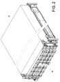
- the cable management device 20 can be brought into an unfolded state by pulling the second rails 36 out relative to the first rails 34 and be brought into the folded state as shown in FIG. 2 by retracting the second rails 36 relative to the first rails 34.
- the cable management device 20 includes at least two cable management arms, such as a first cable management arm 100, a second cable management arm 200, a third cable management arm 300, and a fourth cable management arm 400.
- the cable management arms 100, 200, 300, and 400 are stacked together so that more space is available for use in the rack 24.
- the cable management device 20 further includes an auxiliary member 40 mounted to the second rail 36 of one of the first slide rail assembly 26 and the second slide rail assembly 30.
- the auxiliary member 40 includes an extension base 42 and at least one connecting portion, such as a connecting portion 44a and another connecting portion 44b, both connected to the extension base 42.
- the extension base 42 has a height.
- the two connecting portions 44a and 44b extend in different directions so that the auxiliary member 40 is applicable to both the first slide rail assembly 26 and the second slide rail assembly 30. Thanks to the height of the extension base 42, the connecting portion 44a corresponds to the fourth cable management arm 400.
- the first cable management arm 100, the second cable management arm 200, the third cable management arm 300, and the fourth cable management arm 400 are all configured to include two corresponding portions, such as a first end portion 20a and a second end portion 20b.
- Each cable management arm has a cable management feature, such as a receiving space S, between the first end portion 20a and the second end portion 20b, or each cable management arm is attached with a plurality of cable management features arranged between the first end portion 20a and the second end portion 20b at intervals. These cable management features serve to receive and manage the aforesaid cables.
- the first end portion 20a and the second end portion 20b of the first cable management arm 100 can be connected to the first rails 34 of the two slide rail assemblies (namely the first slide rail assembly 26 and the second slide rail assembly 30) respectively. At least one of the first and second end portions 20a and 20b of the first cable management arm 100 can be further mounted with a connecting member 46 in a detachable manner. In this embodiment, each of the first and second end portions 20a and 20b of the first cable management arm 100 is connected by a connecting member 46 to a connecting base 35 provided adjacent to a rear portion of the first rail 34 of the corresponding slide rail assembly.
- each of the first and second end portions 20a and 20b of the first cable management arm 100 is connected by a connecting member to the corresponding post (e.g., the second post 28b or 32b) of the rack 24.
- a connecting member e.g., the second post 28b or 32b
- the second cable management arm 200 is movably connected to the first cable management arm 100.
- the first end portion 20a of the second cable management arm 200 is movably connected to an upper part of the first cable management arm 100 that is adjacent to the first end portion 20a of the first cable management arm 100.
- the first end portion 20a of the second cable management arm 200 is pivotally connected via a first pivotal connecting member 48 to an upper part of the first cable management arm 100 that is adjacent to the first end portion 20a of the first cable management arm 100.
- the second cable arrangement arm 200 is arranged at a position higher than the first cable management arm 100.
- the third cable management arm 300 is movably connected to the second cable management arm 200.
- the second end portion 20b of the third cable management arm 300 is movably connected to an upper part of the second cable management arm 200 that is adjacent to the second end portion 20b of the second cable management arm 200.
- the second end portion 20b of the third cable management arm 300 is pivotally connected via a second pivotal connecting member 50 to an upper part of the second cable management arm 200 that is adjacent to the second end portion 20b of the second cable management arm 200.
- the third cable arrangement arm 300 is arranged at a position higher than the second cable management arm 200.
- the fourth cable management arm 400 is movably connected to the third cable management arm 300.
- the first end portion 20a of the fourth cable management arm 400 is movably connected to an upper part of the third cable management arm 300 that is adjacent to the first end portion 20a of the third cable management arm 300.
- the first end portion 20a of the fourth cable management arm 400 is pivotally connected via a third pivotal connecting member 52 to an upper part of the third cable management arm 300 that is adjacent to the first end portion 20a of the third cable management arm 300.
- the fourth cable arrangement arm 400 is arranged at a position higher than the third cable management arm 300.
- the second end portion 20b of the fourth cable management arm 400 is connected to the second rail 36 of one of the slide rail assemblies (e.g., the first slide rail assembly 26 or the second slide rail assembly 30) or to the object 22.
- the second end portion 20b of the fourth cable management arm 400 is further mounted with another connecting member 54 in a detachable manner.
- This connecting member 54 can connect the second end portion 20b of the fourth cable management arm 400 to the connecting portion 44a of the auxiliary member 40 that is mounted to the second rail 36 (not shown in FIG. 3 due to limitation of the viewing angle) of the second slide rail assembly 30, in order for the fourth cable management arm 400 to be driven by the second rail 36 of the second slide rail assembly 30 when this second rail 36 is displaced relative to the corresponding first rail 34.
- the cable management device 20 further includes at least one rod which allows two interconnected ones of the cable management arms 100, 200, 300, and 400 to stay within a predetermined range of movement.
- a first rod 150, a second rod 250, and a third rod 350 are provided by way of example.
- the first rod 150 is attached between the first cable management arm 100 and the second cable management arm 200.
- the first rod 150 has a first portion 152 and a second portion 154, wherein the first portion 152 is connected (e.g., pivotally connected) to one of the first and second cable management arms 100 and 200 (e.g., the first cable management arm 100) and the second portion 154 can be driven by the other of the first and second cable management arms 100 and 200 (e.g., the second cable management arm 200).
- the angle hereinafter also referred to as the unfolding angle
- the second cable management arm 200 can be unfolded with respect to the first cable management arm 100 is kept within a predetermined range by the first rod 150.
- one of the first rod 150 and the second cable management arm 200 further has a first guide groove 156.
- a first guide member 158 is attached to one of the first rod 150 and the second cable management arm 200.
- the first rod 150 that has the first guide groove 156
- the first guide member 158 is attached to the second cable management arm 200 and movably mounted in the first guide groove 156. With the first guide member 158 movably mounted in the first guide groove 156, the first rod 150 and the second cable management arm 200 can move relative to each other.
- the second portion 154 forms a blocking portion at a predetermined position of the first guide groove 156 (e.g., the second portion 154 is at a position distant from the first portion 152 of the first rod 150) such that the first guide member 158 can move in the first guide groove 156 only within a range of movement between the first portion 152 and the second portion 154.
- the second rod 250 is attached between the second cable management arm 200 and the third cable management arm 300.
- the second rod 250 has a first portion 252 and a second portion 254, wherein the first portion 252 is connected (e.g., pivotally connected) to one of the second and third cable management arms 200 and 300 (e.g., the second cable management arm 200) and the second portion 254 can be driven by the other of the second and third cable management arms 200 and 300 (e.g., the third cable management arm 300).
- the angle hereinafter also referred to as the unfolding angle
- the third cable management arm 300 can be unfolded with respect to the second cable management arm 200 is kept within a predetermined range by the second rod 250.
- one of the second rod 250 and the third cable management arm 300 further has a second guide groove 256.
- a second guide member 258 is attached to one of the second rod 250 and the third cable management arm 300.
- the second rod 250 that has the second guide groove 256
- the second guide member 258 is attached to the third cable management arm 300 and movably mounted in the second guide groove 256. With the second guide member 258 movably mounted in the second guide groove 256, the second rod 250 and the third cable management arm 300 can move relative to each other.
- the second portion 254 forms a blocking portion at a predetermined position of the second guide groove 256 (e.g., the second portion 254 is at a position distant from the first portion 252 of the second rod 250) such that the second guide member 258 can move in the second guide groove 256 only within a range of movement between the first portion 252 and the second portion 254.
- the third rod 350 is attached between the third cable management arm 300 and the fourth cable management arm 400.
- the third rod 350 has a first portion 352 and a second portion 354, wherein the first portion 352 is connected (e.g., pivotally connected) to one of the third and fourth cable management arms 300 and 400 (e.g., the third cable management arm 300) and the second portion 354 can be driven by the other of the third and fourth cable management arms 300 and 400 (e.g., the fourth cable management arm 400).
- the angle hereinafter also referred to as the unfolding angle
- the fourth cable management arm 400 can be unfolded with respect to the third cable management arm 300 is kept within a predetermined range by the third rod 350.
- one of the third rod 350 and the fourth cable management arm 400 further has a third guide groove 356.
- a third guide member 358 is attached to one of the third rod 350 and the fourth cable management arm 400.
- the third rod 350 that has the third guide groove 356, and the third guide member 358 is attached to the fourth cable management arm 400 and movably mounted in the third guide groove 356.
- the third guide member 358 movably mounted in the third guide groove 356, the third rod 350 and the fourth cable management arm 400 can move relative to each other.
- the second portion 354 forms a blocking portion at a predetermined position of the third guide groove 356 (e.g., the second portion 354 is at a position distant from the first portion 352 of the third rod 350) such that the third guide member 358 can move in the third guide groove 356 only within a range of movement between the first portion 352 and the second portion 354.
- the cable management device 20 may further include a blocking member 56 and an elastic plate 58 provided at the blocking member 56.
- the blocking member 56 has a height corresponding at least to the stacked height of the first cable management arm 100 and the second cable management arm 200.
- the height of the blocking member 56 corresponds to the stacked height of the first cable management arm 100, the second cable management arm 200, and the third cable management arm 300 by way of example.
- the blocking member 56 can produce a blocking effect on the second cable management arm 200 and the third cable management arm 300 while the second cable management arm 200, the third cable management arm 300, and the fourth cable management arm 400 are being folded with respect to the first cable management arm 100.
- the height, and consequently the blocking effect, of the blocking member 56 can be adjusted according to practical needs.
- the blocking member 56 is detachably mounted to one of the first cable management arm 100 and the fourth cable management arm 400.
- the blocking member 56 is mounted to the first cable management arm 100.
- each of the first cable management arm 100 and the fourth cable management arm 400 can be provided with a plurality of mounting portions 60 for mounting the blocking member 56.
- the blocking member 56 itself has a plurality of holes 62.
- the elastic plate 58 corresponds to one of the holes 62.
- Each hole 62 has a large-diameter portion 64 and a small-diameter portion 66 in communication with the large-diameter portion 64 to resemble a keyhole.
- the elastic plate 58 has a stop wall 68 provided adjacent to the border between the large-diameter portion 64 and the small-diameter portion 66 of the corresponding hole 62. According to the arrangement described above, assembly can be carried out by passing each mounting portion 60 of the first cable management arm 100 through the large-diameter portion 64 of the corresponding hole 62 of the blocking member 56 and then displacing the mounting portions 60 to the small-diameter portions 66 of the holes 62 respectively, with the stop wall 68 of the elastic plate 58 blocking one of the mounting portions 60. Thus, the blocking member 56 is rapidly mounted to the first cable management arm 100.
- the elastic plate 58 can be pulled in such a way that the stop wall 68 of the elastic plate 58 no longer blocks the mounting portion 60, and then the blocking member 56 can be rapidly detached from the first cable management arm 100.
- the cable management device 20 is in the folded state when the first slide rail assembly 26 and the second slide rail assembly 30 are in the retracted state.
- the fourth cable management arm 400 of the cable management device 20 is driven to move and gradually unfolds with respect to the third cable management arm 300.
- the cable management device 20 keeps unfolding when the object 22 is further pulled out in the direction D, as shown in FIG. 7 . More specifically, the fourth cable management arm 400 is further moved during the process such that the third cable management arm 300 and the second cable management arm 200 are sequentially driven to displace relative to the first cable management arm 100. Because of the cable management arms 100, 200, 300, and 400, the cable management device 20 can unfold to a greater length than a common two-section cable management arm. Moreover, the first rod 150, the second rod 250, and the third rod 350 can keep relative movement between the first and second cable management arms 100 and 200, between the second and third cable management arms 200 and 300, and between the third and fourth cable management arms 300 and 400 within a predetermined range respectively.
- the angle of pivotal rotation between each two pivotally connected cable management arms is kept in a predetermined range by the corresponding rod, and this allows the cable management arms 100, 200, 300, and 400 to pivot, and hence shift, within a predetermined range of movement.
- the third guide member 358 of the fourth cable management arm 400 will be moved in the third guide groove 356 of the third rod 350 until blocked by the second portion 354 of the third rod 350.
- the fourth cable management arm 400 has reached a limit of its range of movement relative to the third cable management arm 300 and therefore can unfold no more with respect to the third cable management arm 300.
- the angle by which the fourth cable management arm 400 can pivot with respect to the third cable management arm 300 is kept within a predetermined range by the third rod 350.
- movement of the third cable management arm 300 with respect to the second cable management arm 200 is kept within a predetermined range by the second rod 250 (e.g., the angle by which the third cable management arm 300 can pivot with respect to the second cable management arm 200 is kept within a predetermined range by the second rod 250)
- movement of the second cable management arm 200 with respect to the first cable management arm 100 is kept within a predetermined range by the first rod 150 (e.g., the angle by which the second cable management arm 200 can pivot with respect to the first cable management arm 100 is kept within a predetermined range by the first rod 150).
- the operation of the first and second rods 150 and 250 is similar to that of the third rod 350 and for the sake of simplicity will not be described repeatedly.
- the cable management device 20 can be installed in a different way from described above.
- the cable management device 20 can be turned 180 degrees such that the first cable management arm 100 is moved from the bottom layer to the top layer and the fourth cable management arm 400, from the top layer to the bottom layer.
- the blocking member 56 is detached from the mounting portions 60 of the first cable management arm 100 and mounted to the mounting portions 60 of the fourth cable management arm 400.
- the connecting member 46 at the first end portion 20a of the first cable management arm 100 is detached and then mounted to the first end portion 20a of the fourth cable management arm 400.
- the first end portion 20a and the second end portion 20b of the fourth cable management arm 400 can be mounted to the first rails 34 of the second slide rail assembly 30 and of the first slide rail assembly 26 respectively, and the second end portion 20b of the first cable management arm 100 can be mounted to the connecting portion 44a of the auxiliary member 40 that is mounted to the second rail 36 of the first slide rail assembly 26. That is to say, the cable management device 20 of the present invention can be connected to and unfold along with the first slide rail assembly 26 as well as the second slide rail assembly 30 (see FIG. 3 ), thereby providing cable management on either the left or the right side.
- the second end portion 20b of the first cable management arm 100 of the cable management device 20 is so connected that, when the second rail 36 of the first slide rail assembly 26 is displaced relative to the corresponding first rail 34, the first cable management arm 100 is moved and brings the cable management device 20 into an unfolded state.
Landscapes
- Engineering & Computer Science (AREA)
- General Engineering & Computer Science (AREA)
- Computer Hardware Design (AREA)
- Microelectronics & Electronic Packaging (AREA)
- Mechanical Engineering (AREA)
- Electric Cable Arrangement Between Relatively Moving Parts (AREA)
Abstract
Description
- The present invention relates to a cable management device and more particularly to a cable management device for managing the cables of an object (e.g., a piece of electronic equipment).
- A slide rail assembly typically includes at least two slide rails which can be longitudinally displaced relative to each other to bring the slide rail assembly into an extended or retracted state. In a rack-based system, for example, a pair of slide rail assemblies can be used to mount a piece of electronic equipment (e.g., a server) to two pairs of posts of a rack so that the electronic equipment can be pulled out of and retracted into the rack via the pair of slide rail assemblies. Generally, the cables of the electronic equipment are arranged on a cable management arm (CMA), which can keep the cables in neat arrangement while the pair of slide rail assemblies are being pulled out or retracted. Techniques related to cable management arms are disclosed, for instance, in
US Patent Nos. 6,945,504 B2 ;7,712,615 B2 ; and8,231,014 B2 . - The present invention relates to a cable management device for managing the cables of an object.
- According to one aspect of the present invention, a cable management device includes a first cable management arm, a second cable management arm, and a first rod. The second cable management arm is movably connected to the first cable management arm. The first rod is attached between the first cable management arm and the second cable management arm and has a first portion and a second portion, wherein the first portion is connected to one of the first cable management arm and the second cable management arm and the second portion can be driven by the other of the first cable management arm and the second cable management arm. Thus, the angle by which the second cable management arm can be unfolded with respect to the first cable management arm is kept within a predetermined range by the first rod.
- Preferably, the first cable management arm has a first end portion, and the second cable management arm has a first end portion pivotally connected to an upper part of the first cable management arm that is adjacent to the first end portion of the first cable management arm.
- Preferably, the cable management device further includes a third cable management arm and a fourth cable management arm, the fourth cable management arm is pivotally connected to an upper part of the third cable management arm, the second cable management arm further has a second end portion, and the third cable management arm is pivotally connected to an upper part of the second cable management arm that is adjacent to the second end portion of the second cable management arm.
- Preferably, the first portion of the first rod is pivotally connected to the first cable management arm, one of the first rod and the second cable management arm further has a first guide groove, and a first guide member is movably mounted in the first guide groove to enable relative movement of the first rod and the second cable management arm.
- Preferably, the second portion of the first rod forms a blocking portion at a predetermined position of the first guide groove such that the first guide member can move in the first guide groove only within a range of movement between the first portion of the first rod and the second portion of the first rod.
- Preferably, the cable management device further includes a second rod attached between the second cable management arm and the third cable management arm, and the second rod has a first portion and a second portion. The first portion of the second rod is connected to one of the second cable management arm and the third cable management arm. The second portion of the second rod can be driven by the other of the second cable management arm and the third cable management arm. One of the second rod and the third cable management arm further has a second guide groove, and a second guide member is movably mounted in the second guide groove to enable relative movement of the second rod and the third cable management arm. Thus, the angle by which the third cable management arm can be unfolded with respect to the second cable management arm is kept within a predetermined range by the second rod.
- Preferably, the second portion of the second rod forms a blocking portion at a predetermined position of the second guide groove such that the second guide member can move in the second guide groove only within a range of movement between the first portion of the second rod and the second portion of the second rod.
- Preferably, the cable management device further includes a third rod attached between the third cable management arm and the fourth cable management arm, and the third rod has a first portion and a second portion. The first portion of the third rod is connected to one of the third cable management arm and the fourth cable management arm. The second portion of the third rod can be driven by the other of the third cable management arm and the fourth cable management arm. One of the third rod and the fourth cable management arm further has a third guide groove, and a third guide member is movably mounted in the third guide groove to enable relative movement of the third rod and the fourth cable management arm. Thus, the angle by which the fourth cable management arm can be unfolded with respect to the third cable management arm is kept within a predetermined range by the third rod.
- Preferably, the second portion of the third rod forms a blocking portion at a predetermined position of the third guide groove such that the third guide member can move in the third guide groove only within a range of movement between the first portion of the third rod and the second portion of the third rod.
- According to another aspect of the present invention, a cable management device for use with a pair of slide rail assemblies includes a first cable management arm, a second cable management arm, a third cable management arm, a first rod, and a second rod. The first cable management arm has a first end portion and a second end portion which are connected to the slide rail assemblies respectively. The second cable management arm has a first end portion and a second end portion. The first end portion of the second cable management arm is movably connected to the first cable management arm at a position adjacent to the first end portion of the first cable management arm. The third cable management arm is movably connected to the second cable management arm at a position adjacent to the second end portion of the second cable management arm. The first rod is attached between the first cable management arm and the second cable management arm and has a first portion and a second portion, wherein the first portion is connected to one of the first cable management arm and the second cable management arm and the second portion can be driven by the other of the first cable management arm and the second cable management arm. Thus, the angle by which the second cable management arm can be unfolded with respect to the first cable management arm is kept within a predetermined range by the first rod. The second rod is attached between the second cable management arm and the third cable management arm and has a first portion and a second portion. The first portion of the second rod is connected to one of the second cable management arm and the third cable management arm. The second portion of the second rod can be driven by the other of the second cable management arm and the third cable management arm.
- According to still another aspect of the present invention, a cable management device is adapted for use with a rack-based system, wherein the rack-based system provides a pair of slide rail assemblies for mounting an object to two pairs of posts of a rack. Each of the slide rail assemblies includes a first rail and a second rail longitudinally displaceable relative to the first rail. The first rail of each slide rail assembly is attached to a corresponding pair of posts while the second rail of each slide rail assembly is mounted with the object. The cable management device includes a first cable management arm, a second cable management arm, a third cable management arm, and a fourth cable management arm. The first cable management arm includes a first end portion and a second end portion which correspond to each other, wherein the first end portion and the second end portion are connected to the first rails of the slide rail assemblies respectively. The second cable management arm includes a first end portion and a second end portion which correspond to each other. The first end portion of the second cable management arm is movably connected to the first end portion of the first cable management arm. The third cable management arm includes a first end portion and a second end portion which correspond to each other. The second end portion of the third cable management arm is movably connected to the second end portion of the second cable management arm. The fourth cable management arm includes a first end portion and a second end portion which correspond to each other. The first end portion of the fourth cable management arm is movably connected to the first end portion of the third cable management arm. The second end portion of the fourth cable management arm is connected to one of the second rails of the pair of slide rail assemblies or the object.
- One of the advantageous features of applying the present invention is that the cable management device has more than two movably connected cable management arms, and that a rod can be arranged between each two adjacent cable management arms so that relative movement of the two cable management arms is kept within a predetermined range.
-
-
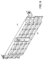
FIG. 1 is a perspective view in which the cable management device in an embodiment of the present invention is applied to a rack-based system and has been brought into an unfolded state by pulling out the second rails of a pair of slide rail assemblies relative to the first rails; -
FIG. 2 is a perspective view of the cable management device inFIG. 1 in the folded state; -
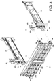
FIG. 3 is an exploded perspective view of the cable management device in an embodiment of the present invention, showing that the first cable management arm can be connected to the first rails of a pair of slide rail assemblies, and that a portion of the fourth cable management arm can be connected to the auxiliary member of the second rail of one of the slide rail assemblies; -
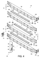
FIG. 4 is an exploded perspective view of the cable management device in an embodiment of the present invention; -
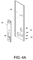
FIG. 4A is an exploded perspective view of the blocking member and the elastic plate in an embodiment of the present invention; -
FIG. 5 is a top view in which the cable management device in an embodiment of the present invention is in the folded stated while a pair of slide rail assemblies are in the retracted state; -
FIG. 6 is a top view showing how the cable management device inFIG. 5 gradually unfolds while an object is pulled via the pair of slide rail assemblies to a position outside a rack; -
FIG. 7 is a top view showing how the cable management device inFIG. 6 further unfolds while the object is further pulled out of the rack; -
FIG. 8 is a perspective view in which the cable management device in an embodiment of the present invention is in the folded state, showing that the cable management device can also be turned upside down for installation; -
FIG. 9 is a perspective view of the cable management device inFIG. 8 after it is turned upside down, with the cable management arms stacked in a reverse order; -
FIG. 10 is another perspective view of the cable management device inFIG. 8 after it is turned upside down, with the blocking member detached from the first cable management arm, and the connecting member previously at the first end portion of the first cable management arm also detached; -
FIG. 11 is yet another perspective view of the cable management device inFIG. 8 after it is turned upside down, with the blocking member mounted to the fourth cable management arm, and the connecting member previously at the first end portion of the first cable management arm now mounted to the first end portion of the fourth cable management arm, showing that the fourth cable management arm can be connected to the first rails of a pair of slide rail assemblies, and that a portion of the first cable management arm can be connected to the auxiliary member of the second rail of one of the slide rail assemblies; and -
FIG. 12 is a perspective view showing that the first cable management arm of the cable management device inFIG. 11 is connected to the first slide rail assembly, and that the cable management device can be brought into an unfolded state by moving the second rail of the first slide rail assembly relative to the corresponding first rail. -
FIG. 1 shows acable management device 20 in an embodiment of the present invention. Thecable management device 20 is adapted for use with a rack-based system configured to mount anobject 22 to arack 24. Theobject 22 can be the chassis of a piece of electronic equipment or any other article to be supported in therack 24; the present invention imposes no limitations in this respect. Theobject 22 is mounted on two opposite sides to two pairs of posts of therack 24 via a pair of slide rail assemblies respectively. More specifically, one lateral side of theobject 22 is mounted to one pair of posts, e.g., afirst post 28a and asecond post 28b, via a firstslide rail assembly 26, and the opposite lateral side of theobject 22 is mounted to the other pair of posts, e.g., afirst post 32a and asecond post 32b, via a secondslide rail assembly 30. Each of the firstslide rail assembly 26 and the secondslide rail assembly 30 includes afirst rail 34 and asecond rail 36 longitudinally displaceable relative to thefirst rail 34, and preferably further includes athird rail 38 movably connected between thefirst rail 34 and thesecond rail 36 to increase the distance by which thesecond rail 36 can be displaced relative to thefirst rail 34. Thefirst rail 34 of each slide rail assembly is attached to the corresponding pair of posts while thesecond rail 36 of each slide rail assembly is mounted with theobject 22. According to the arrangement described above, theobject 22 can be pulled out of and retracted into therack 24. Thecable management device 20 serves to support or store the cables (not shown) extending from and lying behind theobject 22. Thecable management device 20 can be brought into an unfolded state by pulling thesecond rails 36 out relative to thefirst rails 34 and be brought into the folded state as shown inFIG. 2 by retracting thesecond rails 36 relative to the first rails 34. - Referring to
FIG. 3 , thecable management device 20 includes at least two cable management arms, such as a firstcable management arm 100, a secondcable management arm 200, a thirdcable management arm 300, and a fourthcable management arm 400. When in the folded state, thecable management arms rack 24. Preferably, thecable management device 20 further includes anauxiliary member 40 mounted to thesecond rail 36 of one of the firstslide rail assembly 26 and the secondslide rail assembly 30. Theauxiliary member 40 includes anextension base 42 and at least one connecting portion, such as a connectingportion 44a and another connectingportion 44b, both connected to theextension base 42. Theextension base 42 has a height. The two connectingportions auxiliary member 40 is applicable to both the firstslide rail assembly 26 and the secondslide rail assembly 30. Thanks to the height of theextension base 42, the connectingportion 44a corresponds to the fourthcable management arm 400. - As shown in
FIG. 3 andFIG. 4 , the firstcable management arm 100, the secondcable management arm 200, the thirdcable management arm 300, and the fourthcable management arm 400 are all configured to include two corresponding portions, such as afirst end portion 20a and asecond end portion 20b. Each cable management arm has a cable management feature, such as a receiving space S, between thefirst end portion 20a and thesecond end portion 20b, or each cable management arm is attached with a plurality of cable management features arranged between thefirst end portion 20a and thesecond end portion 20b at intervals. These cable management features serve to receive and manage the aforesaid cables. - The
first end portion 20a and thesecond end portion 20b of the firstcable management arm 100 can be connected to thefirst rails 34 of the two slide rail assemblies (namely the firstslide rail assembly 26 and the second slide rail assembly 30) respectively. At least one of the first andsecond end portions cable management arm 100 can be further mounted with a connectingmember 46 in a detachable manner. In this embodiment, each of the first andsecond end portions cable management arm 100 is connected by a connectingmember 46 to a connectingbase 35 provided adjacent to a rear portion of thefirst rail 34 of the corresponding slide rail assembly. Alternatively, in an embodiment that is not shown, each of the first andsecond end portions cable management arm 100 is connected by a connecting member to the corresponding post (e.g., thesecond post rack 24. The present invention imposes no limitations in this regard. - The second
cable management arm 200 is movably connected to the firstcable management arm 100. For instance, thefirst end portion 20a of the secondcable management arm 200 is movably connected to an upper part of the firstcable management arm 100 that is adjacent to thefirst end portion 20a of the firstcable management arm 100. More specifically, thefirst end portion 20a of the secondcable management arm 200 is pivotally connected via a first pivotal connectingmember 48 to an upper part of the firstcable management arm 100 that is adjacent to thefirst end portion 20a of the firstcable management arm 100. As a result, the secondcable arrangement arm 200 is arranged at a position higher than the firstcable management arm 100. - The third
cable management arm 300 is movably connected to the secondcable management arm 200. For instance, thesecond end portion 20b of the thirdcable management arm 300 is movably connected to an upper part of the secondcable management arm 200 that is adjacent to thesecond end portion 20b of the secondcable management arm 200. More specifically, thesecond end portion 20b of the thirdcable management arm 300 is pivotally connected via a second pivotal connectingmember 50 to an upper part of the secondcable management arm 200 that is adjacent to thesecond end portion 20b of the secondcable management arm 200. As a result, the thirdcable arrangement arm 300 is arranged at a position higher than the secondcable management arm 200. - The fourth
cable management arm 400 is movably connected to the thirdcable management arm 300. For instance, thefirst end portion 20a of the fourthcable management arm 400 is movably connected to an upper part of the thirdcable management arm 300 that is adjacent to thefirst end portion 20a of the thirdcable management arm 300. More specifically, thefirst end portion 20a of the fourthcable management arm 400 is pivotally connected via a third pivotal connectingmember 52 to an upper part of the thirdcable management arm 300 that is adjacent to thefirst end portion 20a of the thirdcable management arm 300. As a result, the fourthcable arrangement arm 400 is arranged at a position higher than the thirdcable management arm 300. On the other hand, thesecond end portion 20b of the fourthcable management arm 400 is connected to thesecond rail 36 of one of the slide rail assemblies (e.g., the firstslide rail assembly 26 or the second slide rail assembly 30) or to theobject 22. In this embodiment, thesecond end portion 20b of the fourthcable management arm 400 is further mounted with another connectingmember 54 in a detachable manner. This connectingmember 54 can connect thesecond end portion 20b of the fourthcable management arm 400 to the connectingportion 44a of theauxiliary member 40 that is mounted to the second rail 36 (not shown inFIG. 3 due to limitation of the viewing angle) of the secondslide rail assembly 30, in order for the fourthcable management arm 400 to be driven by thesecond rail 36 of the secondslide rail assembly 30 when thissecond rail 36 is displaced relative to the correspondingfirst rail 34. - Preferably, the
cable management device 20 further includes at least one rod which allows two interconnected ones of thecable management arms first rod 150, asecond rod 250, and athird rod 350 are provided by way of example. - The
first rod 150 is attached between the firstcable management arm 100 and the secondcable management arm 200. In this embodiment, thefirst rod 150 has afirst portion 152 and asecond portion 154, wherein thefirst portion 152 is connected (e.g., pivotally connected) to one of the first and secondcable management arms 100 and 200 (e.g., the first cable management arm 100) and thesecond portion 154 can be driven by the other of the first and secondcable management arms 100 and 200 (e.g., the second cable management arm 200). Thus, the angle (hereinafter also referred to as the unfolding angle) by which the secondcable management arm 200 can be unfolded with respect to the firstcable management arm 100 is kept within a predetermined range by thefirst rod 150. More specifically, one of thefirst rod 150 and the secondcable management arm 200 further has afirst guide groove 156. In addition, afirst guide member 158 is attached to one of thefirst rod 150 and the secondcable management arm 200. Here, by way of example, it is thefirst rod 150 that has thefirst guide groove 156, and thefirst guide member 158 is attached to the secondcable management arm 200 and movably mounted in thefirst guide groove 156. With thefirst guide member 158 movably mounted in thefirst guide groove 156, thefirst rod 150 and the secondcable management arm 200 can move relative to each other. Besides, thesecond portion 154 forms a blocking portion at a predetermined position of the first guide groove 156 (e.g., thesecond portion 154 is at a position distant from thefirst portion 152 of the first rod 150) such that thefirst guide member 158 can move in thefirst guide groove 156 only within a range of movement between thefirst portion 152 and thesecond portion 154. - The
second rod 250 is attached between the secondcable management arm 200 and the thirdcable management arm 300. In this embodiment, thesecond rod 250 has afirst portion 252 and asecond portion 254, wherein thefirst portion 252 is connected (e.g., pivotally connected) to one of the second and thirdcable management arms 200 and 300 (e.g., the second cable management arm 200) and thesecond portion 254 can be driven by the other of the second and thirdcable management arms 200 and 300 (e.g., the third cable management arm 300). Thus, the angle (hereinafter also referred to as the unfolding angle) by which the thirdcable management arm 300 can be unfolded with respect to the secondcable management arm 200 is kept within a predetermined range by thesecond rod 250. More specifically, one of thesecond rod 250 and the thirdcable management arm 300 further has asecond guide groove 256. In addition, asecond guide member 258 is attached to one of thesecond rod 250 and the thirdcable management arm 300. Here, by way of example, it is thesecond rod 250 that has thesecond guide groove 256, and thesecond guide member 258 is attached to the thirdcable management arm 300 and movably mounted in thesecond guide groove 256. With thesecond guide member 258 movably mounted in thesecond guide groove 256, thesecond rod 250 and the thirdcable management arm 300 can move relative to each other. Besides, thesecond portion 254 forms a blocking portion at a predetermined position of the second guide groove 256 (e.g., thesecond portion 254 is at a position distant from thefirst portion 252 of the second rod 250) such that thesecond guide member 258 can move in thesecond guide groove 256 only within a range of movement between thefirst portion 252 and thesecond portion 254. - The
third rod 350 is attached between the thirdcable management arm 300 and the fourthcable management arm 400. In this embodiment, thethird rod 350 has afirst portion 352 and asecond portion 354, wherein thefirst portion 352 is connected (e.g., pivotally connected) to one of the third and fourthcable management arms 300 and 400 (e.g., the third cable management arm 300) and thesecond portion 354 can be driven by the other of the third and fourthcable management arms 300 and 400 (e.g., the fourth cable management arm 400). Thus, the angle (hereinafter also referred to as the unfolding angle) by which the fourthcable management arm 400 can be unfolded with respect to the thirdcable management arm 300 is kept within a predetermined range by thethird rod 350. More specifically, one of thethird rod 350 and the fourthcable management arm 400 further has athird guide groove 356. In addition, athird guide member 358 is attached to one of thethird rod 350 and the fourthcable management arm 400. Here, by way of example, it is thethird rod 350 that has thethird guide groove 356, and thethird guide member 358 is attached to the fourthcable management arm 400 and movably mounted in thethird guide groove 356. With thethird guide member 358 movably mounted in thethird guide groove 356, thethird rod 350 and the fourthcable management arm 400 can move relative to each other. Besides, thesecond portion 354 forms a blocking portion at a predetermined position of the third guide groove 356 (e.g., thesecond portion 354 is at a position distant from thefirst portion 352 of the third rod 350) such that thethird guide member 358 can move in thethird guide groove 356 only within a range of movement between thefirst portion 352 and thesecond portion 354. - The
cable management device 20 may further include a blockingmember 56 and anelastic plate 58 provided at the blockingmember 56. The blockingmember 56 has a height corresponding at least to the stacked height of the firstcable management arm 100 and the secondcable management arm 200. Here, the height of the blockingmember 56 corresponds to the stacked height of the firstcable management arm 100, the secondcable management arm 200, and the thirdcable management arm 300 by way of example. The blockingmember 56 can produce a blocking effect on the secondcable management arm 200 and the thirdcable management arm 300 while the secondcable management arm 200, the thirdcable management arm 300, and the fourthcable management arm 400 are being folded with respect to the firstcable management arm 100. In practice, the height, and consequently the blocking effect, of the blockingmember 56 can be adjusted according to practical needs. The blockingmember 56 is detachably mounted to one of the firstcable management arm 100 and the fourthcable management arm 400. Here, by way of example, the blockingmember 56 is mounted to the firstcable management arm 100. More specifically, each of the firstcable management arm 100 and the fourthcable management arm 400 can be provided with a plurality of mountingportions 60 for mounting the blockingmember 56. The blockingmember 56 itself has a plurality ofholes 62. As shown inFIG. 4 andFIG. 4A , theelastic plate 58 corresponds to one of theholes 62. Eachhole 62 has a large-diameter portion 64 and a small-diameter portion 66 in communication with the large-diameter portion 64 to resemble a keyhole. Theelastic plate 58 has astop wall 68 provided adjacent to the border between the large-diameter portion 64 and the small-diameter portion 66 of the correspondinghole 62. According to the arrangement described above, assembly can be carried out by passing each mountingportion 60 of the firstcable management arm 100 through the large-diameter portion 64 of the correspondinghole 62 of the blockingmember 56 and then displacing the mountingportions 60 to the small-diameter portions 66 of theholes 62 respectively, with thestop wall 68 of theelastic plate 58 blocking one of the mountingportions 60. Thus, the blockingmember 56 is rapidly mounted to the firstcable management arm 100. When it is desired to remove the blockingmember 56 from the firstcable management arm 100, theelastic plate 58 can be pulled in such a way that thestop wall 68 of theelastic plate 58 no longer blocks the mountingportion 60, and then the blockingmember 56 can be rapidly detached from the firstcable management arm 100. - Referring to
FIG. 5 , thecable management device 20 is in the folded state when the firstslide rail assembly 26 and the secondslide rail assembly 30 are in the retracted state. - When the
object 22 is displaced by pulling thesecond rails 36 out of therack 24 in a direction D relative to thefirst rails 34, as shown inFIG. 6 , the fourthcable management arm 400 of thecable management device 20 is driven to move and gradually unfolds with respect to the thirdcable management arm 300. - The
cable management device 20 keeps unfolding when theobject 22 is further pulled out in the direction D, as shown inFIG. 7 . More specifically, the fourthcable management arm 400 is further moved during the process such that the thirdcable management arm 300 and the secondcable management arm 200 are sequentially driven to displace relative to the firstcable management arm 100. Because of thecable management arms cable management device 20 can unfold to a greater length than a common two-section cable management arm. Moreover, thefirst rod 150, thesecond rod 250, and thethird rod 350 can keep relative movement between the first and secondcable management arms cable management arms cable management arms cable management arms cable management arm 400 is being unfolded with respect to the thirdcable management arm 300, thethird guide member 358 of the fourthcable management arm 400 will be moved in thethird guide groove 356 of thethird rod 350 until blocked by thesecond portion 354 of thethird rod 350. Once thethird guide member 358 is prevented from further displacement in thethird guide groove 356, the fourthcable management arm 400 has reached a limit of its range of movement relative to the thirdcable management arm 300 and therefore can unfold no more with respect to the thirdcable management arm 300. In this embodiment, for example, the angle by which the fourthcable management arm 400 can pivot with respect to the thirdcable management arm 300 is kept within a predetermined range by thethird rod 350. By the same token, movement of the thirdcable management arm 300 with respect to the secondcable management arm 200 is kept within a predetermined range by the second rod 250 (e.g., the angle by which the thirdcable management arm 300 can pivot with respect to the secondcable management arm 200 is kept within a predetermined range by the second rod 250), and movement of the secondcable management arm 200 with respect to the firstcable management arm 100 is kept within a predetermined range by the first rod 150 (e.g., the angle by which the secondcable management arm 200 can pivot with respect to the firstcable management arm 100 is kept within a predetermined range by the first rod 150). The operation of the first andsecond rods third rod 350 and for the sake of simplicity will not be described repeatedly. - Referring to
FIG. 8 andFIG. 9 , thecable management device 20 can be installed in a different way from described above. For example, thecable management device 20 can be turned 180 degrees such that the firstcable management arm 100 is moved from the bottom layer to the top layer and the fourthcable management arm 400, from the top layer to the bottom layer. - Further, as shown in
FIG. 10 andFIG. 11 , the blockingmember 56 is detached from the mountingportions 60 of the firstcable management arm 100 and mounted to the mountingportions 60 of the fourthcable management arm 400. Also, the connectingmember 46 at thefirst end portion 20a of the firstcable management arm 100 is detached and then mounted to thefirst end portion 20a of the fourthcable management arm 400. Thus, thefirst end portion 20a and thesecond end portion 20b of the fourthcable management arm 400 can be mounted to thefirst rails 34 of the secondslide rail assembly 30 and of the firstslide rail assembly 26 respectively, and thesecond end portion 20b of the firstcable management arm 100 can be mounted to the connectingportion 44a of theauxiliary member 40 that is mounted to thesecond rail 36 of the firstslide rail assembly 26. That is to say, thecable management device 20 of the present invention can be connected to and unfold along with the firstslide rail assembly 26 as well as the second slide rail assembly 30 (seeFIG. 3 ), thereby providing cable management on either the left or the right side. - As shown in
FIG. 12 , thesecond end portion 20b of the firstcable management arm 100 of thecable management device 20 is so connected that, when thesecond rail 36 of the firstslide rail assembly 26 is displaced relative to the correspondingfirst rail 34, the firstcable management arm 100 is moved and brings thecable management device 20 into an unfolded state. - While the present invention has been disclosed through the foregoing preferred embodiments, the embodiments are not intended to be restrictive of the invention. The scope of patent protection sought by the applicant is defined by the appended claims.
Claims (14)
- A cable management device (20), comprising:a first cable management arm (100);a second cable management arm (200) movably connected to the first cable management arm (100); anda first rod (150) attached between the first cable management arm (100) and the second cable management arm (200), the first rod (150) having a first portion (152) and a second portion (154), wherein the first portion (152) of the first rod (150) is connected to one of the first cable management arm (100) and the second cable management arm (200), and the second portion (154) of the first rod (150) is configured to be driven by the other of the first cable management arm (100) and the second cable management arm (200), such that an unfolding angle of the second cable management arm (200) with respect to the first cable management arm (100) is kept within a predetermined range by the first rod (150).
- The cable management device (20) as claimed in claim 1, wherein the cable management device (20) is configured for use with a pair of slide rail assemblies (26, 30), and wherein the first cable management arm (100) has a first end portion (20a) and a second end portion (20b), and the first end portion (20a) and the second end portion (20b) of the first cable management arm (100) are respectively connected to the slide rail assemblies (26, 30).
- The cable management device (20) as claimed in claim 1, wherein the cable management device (20) is adapted to managing cables of an object (22) mounted between a second rail (36) of a first slide rail assembly (26) and a second rail (36) of a second slide rail assembly (30) in a rack-based system, and wherein the first cable management arm (100) has a first end portion (20a) and a second end portion (20b), and the first end portion (20a) and the second end portion (20b) of the first cable management (100) are connected to a first rail (34) of the first slide rail assembly (26) and a first rail (34) of the second slide rail assembly (30) respectively.
- The cable management device (20) as claimed in claim 1, wherein the first cable management arm (100) has a first end portion (20a), and the second cable management arm (200) has a first end portion (20a) pivotally connected to an upper part of the first cable management arm (100) that is adjacent to the first end portion (20a) of the first cable management arm (100).
- The cable management device (20) as claimed in claim 2 or 3, wherein the second cable management arm (200) has a first end portion (20a) pivotally connected to an upper part of the first cable management arm (100) that is adjacent to the first end portion (20a) of the first cable management arm (100).
- The cable management device (20) as claimed in claim 4 or 5, further comprising a third cable management arm (300) and a fourth cable management arm (400), the fourth cable management arm (400) being pivotally connected to an upper part of the third cable management arm (300), the second cable management arm (200) having a second end portion (20b), the third cable management arm (300) being pivotally connected to an upper part of the second cable management arm (200) that is adjacent to the second end portion (20b) of the second cable management arm (200).
- The cable management device (20) as claimed in any one of claims 1-3, wherein the first portion (152) of the first rod (150) is pivotally connected to the first cable management arm (100), one of the first rod (150) and the second cable management arm (200) has a first guide groove (156), the other of the first rod (150) and the second cable management arm (200) has a first guide member (158) attached thereto, and the first guide member (158) is movably mounted in the first guide groove (156) to enable relative movement of the first rod (150) and the second cable management arm (200).
- The cable management device (20) as claimed in claim 7, wherein the first guide groove (156) is disposed on the first rod (150), the first guide member (158) is attached to the second cable management arm (200), and the second portion (154) of the first rod (150) forms a blocking portion at a predetermined position of the first guide groove (156) such that the first guide member (158) is movable in the first guide groove (156) only within a range of movement between the first portion (152) of the first rod (150) and the second portion (154) of the first rod (150).
- The cable management device (20) as claimed in claim 6, further comprising a second rod (250) attached between the second cable management arm (200) and the third cable management arm (300), the second rod (250) having a first portion (252) and a second portion (254), wherein the first portion (252) of the second rod (250) is connected to one of the second cable management arm (200) and the third cable management arm (300), the second portion (254) of the second rod (250) is configured to be driven by the other of the second cable management arm (200) and the third cable management arm (300), one of the second rod (250) and the third cable management arm (300) has a second guide groove (256), the other of the second rod (250) and the third cable management arm (300) has a second guide member (258) attached thereto, and the second guide member (258) is movably mounted in the second guide groove (256) to enable relative movement of the second rod (250) and the third cable management arm (300), such that an unfolding angle of the third cable management arm (300) with respect to the second cable management arm (200) is kept within a predetermined range by the second rod (250).
- The cable management device (20) as claimed in claim 9, wherein the second guide groove (256) is disposed on the second rod (250), the second guide member (258) is attached to the third cable management arm (300), and the second portion (254) of the second rod (250) forms a blocking portion at a predetermined position of the second guide groove (256) such that the second guide member (258) is movable in the second guide groove (256) only within a range of movement between the first portion (252) of the second rod (250) and the second portion (254) of the second rod (250).
- The cable management device (20) as claimed in claim 6, further comprising a third rod (350) attached between the third cable management arm (300) and the fourth cable management arm (400), the third rod (350) having a first portion (352) and a second portion (354), wherein the first portion (352) of the third rod (350) is connected to one of the third cable management arm (300) and the fourth cable management arm (400), the second portion (354) of the third rod (350) is configured to be driven by the other of the third cable management arm (300) and the fourth cable management arm (400), one of the third rod (350) and the fourth cable management arm (400) has a third guide groove (356), the other of the third rod (350) and the fourth cable management arm (400) has a third guide member (358) attached thereto, and the third guide member (358) is movably mounted in the third guide groove (356) to enable relative movement of the third rod (350) and the fourth cable management arm (400), such that an unfolding angle of the fourth cable management arm (400) with respect to the third cable management arm (300) is kept within a predetermined range by the third rod (350).
- The cable management device (20) as claimed in claim 11, wherein the third guide groove (356) is disposed on the third rod (350), the third guide member (358) is attached to the fourth cable management arm (400), and the second portion (354) of the third rod (350) forms a blocking portion at a predetermined position of the third guide groove (356) such that the third guide member (358) is movable in the third guide groove (356) only within a range of movement between the first portion (352) of the third rod (350) and the second portion (354) of the third rod (350).
- The cable management device (20) as claimed in any one of claims 6 and 9-12, further comprising a blocking member (56) detachably mounted to one of the first cable management arm (100) and the fourth cable management arm (400), the blocking member (56) having a height in order to provide a blocking effect when the second cable management arm (200) and the third cable management arm (300) of the cable management device (20) are being folded relative to the first cable management arm (100).
- The cable management device (20) as claimed in claim 13, further comprising an elastic plate (58) provided at the blocking member (56), each of the first cable management arm (100) and the fourth cable management arm (400) having a plurality of mounting portions (60) for mounting the blocking member (56), the blocking member (56) having a plurality of holes (62), the elastic plate (58) corresponding to one of the holes (62), each said hole (62) having a large-diameter portion (64) and a small-diameter portion (66) in communication with the large-diameter portion (64), the elastic plate (58) having a stop wall (68) provided adjacent to a border between the large-diameter portion (64) and the small-diameter portion (66) of the corresponding hole (62).
Applications Claiming Priority (1)
| Application Number | Priority Date | Filing Date | Title |
|---|---|---|---|
| TW104114358A TWI556711B (en) | 2015-05-05 | 2015-05-05 | Cable management device |
Publications (2)
| Publication Number | Publication Date |
|---|---|
| EP3091825A1 true EP3091825A1 (en) | 2016-11-09 |
| EP3091825B1 EP3091825B1 (en) | 2019-06-12 |
Family
ID=55072532
Family Applications (1)
| Application Number | Title | Priority Date | Filing Date |
|---|---|---|---|
| EP16150187.9A Active EP3091825B1 (en) | 2015-05-05 | 2016-01-05 | Cable management device |
Country Status (4)
| Country | Link |
|---|---|
| US (1) | US9668372B2 (en) |
| EP (1) | EP3091825B1 (en) |
| JP (1) | JP6254573B2 (en) |
| TW (1) | TWI556711B (en) |
Cited By (2)
| Publication number | Priority date | Publication date | Assignee | Title |
|---|---|---|---|---|
| EP3442316A1 (en) * | 2017-08-10 | 2019-02-13 | King Slide Works Co., Ltd. | Cable management device and connecting assembly for rack system |
| WO2020065608A1 (en) * | 2018-09-28 | 2020-04-02 | Pnp Discover Srl | Auxiliary system for industrial plants |
Families Citing this family (19)
| Publication number | Priority date | Publication date | Assignee | Title |
|---|---|---|---|---|
| CA2959323A1 (en) * | 2016-02-29 | 2017-08-29 | Masterbrand Cabinets, Inc. | Compact drawer outlet |
| TWI600242B (en) * | 2016-08-31 | 2017-09-21 | 川湖科技股份有限公司 | Slide rail assembly and cable management device thereof |
| US10292299B2 (en) * | 2016-09-29 | 2019-05-14 | Facebook, Inc. | Cable management system |
| US10291969B2 (en) * | 2017-02-14 | 2019-05-14 | Go!Foton Holdings, Inc. | Rear cable management |
| US10117348B2 (en) | 2017-03-09 | 2018-10-30 | International Business Machines Corporation | Cable management bracket |
| US10575429B2 (en) | 2017-04-04 | 2020-02-25 | Cisco Technology, Inc. | Adjustable cable management slide and direction control for optimized routing |
| TWI617233B (en) * | 2017-06-28 | 2018-03-01 | 川湖科技股份有限公司 | Rack system and connecting assembly for rack system |
| CN109219304B (en) * | 2017-07-04 | 2020-05-19 | 川湖科技股份有限公司 | Connection assembly for rack system |
| JP7156657B2 (en) * | 2017-09-12 | 2022-10-19 | Necプラットフォームズ株式会社 | cable support unit |
| TWI649512B (en) * | 2018-02-07 | 2019-02-01 | 川湖科技股份有限公司 | Connecting device |
| US11047743B2 (en) * | 2018-07-23 | 2021-06-29 | International Business Machines Corporation | Cognitive thermal cable holder |
| TWI683637B (en) * | 2018-07-27 | 2020-02-01 | 川湖科技股份有限公司 | Support assembly and cable management kit |
| TWI677275B (en) * | 2018-08-20 | 2019-11-11 | 川湖科技股份有限公司 | Coupling assembly and cable management device thereof |
| WO2020148596A1 (en) * | 2019-01-14 | 2020-07-23 | Igus Gmbh | Compact conduit for clean room applications, and casing and clamping fixture for said conduit |
| TWI681703B (en) | 2019-02-25 | 2020-01-01 | 川湖科技股份有限公司 | Slide rail mechanism and supporting assembly thereof |
| US11464131B2 (en) * | 2020-02-07 | 2022-10-04 | Seagate Technology Llc | Cable management assembly |
| EP3971622A1 (en) | 2020-07-02 | 2022-03-23 | Go!Foton Holdings, Inc. | Intelligent optical switch |
| JP7479245B2 (en) * | 2020-08-20 | 2024-05-08 | 株式会社クボタ | Wire rod support device and work vehicle |
| TWI792431B (en) * | 2021-07-21 | 2023-02-11 | 新加坡商鴻運科股份有限公司 | Cable management device |
Citations (6)
| Publication number | Priority date | Publication date | Assignee | Title |
|---|---|---|---|---|
| US6945504B2 (en) | 2002-08-20 | 2005-09-20 | King Slide Works Co., Ltd. | Adjustable cable management arm for furniture |
| US20070017883A1 (en) * | 2005-07-19 | 2007-01-25 | International Business Machines Corporation | Cable management system with adjustable length arm |
| DE202008011723U1 (en) * | 2007-09-06 | 2008-12-24 | King Slide Works Co., Ltd., Lu-Chu Hsiang | Cable rack mount |
| US7712615B2 (en) | 2004-10-15 | 2010-05-11 | King Slide Works Co., Ltd. | Support slide assembly for cable management arm |
| US20100193646A1 (en) * | 2008-09-03 | 2010-08-05 | King Slide Works Co., Ltd. | Support slide assembly for a cable management arm |
| EP2744314A1 (en) * | 2012-12-13 | 2014-06-18 | King Slide Works Co., Ltd. | Cable Management Arm |
Family Cites Families (19)
| Publication number | Priority date | Publication date | Assignee | Title |
|---|---|---|---|---|
| JPS6321142Y2 (en) * | 1981-03-20 | 1988-06-10 | ||
| US5746389A (en) * | 1996-12-18 | 1998-05-05 | E-Systems, Inc. | Cable retractor |
| US6070742A (en) | 1998-10-28 | 2000-06-06 | Dell Usa, L.P. | Multi-segment, nesting, low profile cable management arm |
| US6972949B1 (en) | 2003-12-03 | 2005-12-06 | Unisys Corporation | Cable routing system |
| JP3116135U (en) * | 2004-12-08 | 2005-12-02 | 川湖科技股▲分▼有限公司 | Cable management arm |
| US7258583B1 (en) | 2005-01-31 | 2007-08-21 | Central Industrial Supply Company | Cable management arm having cable retention members |
| JP2009254156A (en) * | 2008-04-08 | 2009-10-29 | Hitachi Kokusai Electric Inc | Cable guiding arrangement |
| CN101562958B (en) * | 2008-04-16 | 2012-11-21 | 鸿富锦精密工业(深圳)有限公司 | Wire-management device |
| US8564946B2 (en) * | 2009-01-08 | 2013-10-22 | Hewlett-Packard Development Company, L.P. | Computer including hot-pluggable disk storage drives that are mounted in an in-line arrangement |
| US20100181440A1 (en) * | 2009-01-21 | 2010-07-22 | Ortronics, Inc. | Articulated Cable Management Systems and Methods For Use Thereof |
| JP2012156197A (en) | 2011-01-24 | 2012-08-16 | Yaskawa Electric Corp | Electrical apparatus |
| TWM449433U (en) * | 2012-06-20 | 2013-03-21 | Echostreams Innovative Solutions | Wire organizing holder and its casing segment |
| US9144174B2 (en) * | 2012-12-07 | 2015-09-22 | King Slide Works Co., Ltd. | Cable management arm assembly |
| TWI478456B (en) * | 2013-02-22 | 2015-03-21 | King Slide Works Co Ltd | Cable management arm |
| US9617796B2 (en) * | 2013-10-04 | 2017-04-11 | Electro Mechanical Industries, Inc. | Cable management system |
| US9370121B2 (en) * | 2014-03-24 | 2016-06-14 | King Slide Works Co., Ltd. | Cable management device |
| US20150342081A1 (en) * | 2014-05-22 | 2015-11-26 | Nan Juen International Co., Ltd. | Case cable organizer structure |
| JP3197090U (en) * | 2015-02-06 | 2015-04-16 | 川湖科技股▲分▼有限公司 | Cable management kit |
| US9332669B1 (en) * | 2015-02-13 | 2016-05-03 | Martas Precision Slide Co., Ltd. | Cable management arm of server rack |
-
2015
- 2015-05-05 TW TW104114358A patent/TWI556711B/en active
- 2015-12-11 US US14/966,304 patent/US9668372B2/en active Active
- 2015-12-28 JP JP2015256131A patent/JP6254573B2/en active Active
-
2016
- 2016-01-05 EP EP16150187.9A patent/EP3091825B1/en active Active
Patent Citations (7)
| Publication number | Priority date | Publication date | Assignee | Title |
|---|---|---|---|---|
| US6945504B2 (en) | 2002-08-20 | 2005-09-20 | King Slide Works Co., Ltd. | Adjustable cable management arm for furniture |
| US7712615B2 (en) | 2004-10-15 | 2010-05-11 | King Slide Works Co., Ltd. | Support slide assembly for cable management arm |
| US20070017883A1 (en) * | 2005-07-19 | 2007-01-25 | International Business Machines Corporation | Cable management system with adjustable length arm |
| DE202008011723U1 (en) * | 2007-09-06 | 2008-12-24 | King Slide Works Co., Ltd., Lu-Chu Hsiang | Cable rack mount |
| US20100193646A1 (en) * | 2008-09-03 | 2010-08-05 | King Slide Works Co., Ltd. | Support slide assembly for a cable management arm |
| US8231014B2 (en) | 2008-09-03 | 2012-07-31 | King Slide Works Co., Ltd. | Support slide assembly for a cable management arm |
| EP2744314A1 (en) * | 2012-12-13 | 2014-06-18 | King Slide Works Co., Ltd. | Cable Management Arm |
Cited By (2)
| Publication number | Priority date | Publication date | Assignee | Title |
|---|---|---|---|---|
| EP3442316A1 (en) * | 2017-08-10 | 2019-02-13 | King Slide Works Co., Ltd. | Cable management device and connecting assembly for rack system |
| WO2020065608A1 (en) * | 2018-09-28 | 2020-04-02 | Pnp Discover Srl | Auxiliary system for industrial plants |
Also Published As
| Publication number | Publication date |
|---|---|
| EP3091825B1 (en) | 2019-06-12 |
| TWI556711B (en) | 2016-11-01 |
| TW201640985A (en) | 2016-11-16 |
| JP6254573B2 (en) | 2017-12-27 |
| US9668372B2 (en) | 2017-05-30 |
| JP2016213433A (en) | 2016-12-15 |
| US20160330859A1 (en) | 2016-11-10 |
Similar Documents
| Publication | Publication Date | Title |
|---|---|---|
| EP3091825B1 (en) | Cable management device | |
| US10910804B2 (en) | Cable management device and coupling assembly for rack system | |
| US9861193B2 (en) | Bracket device | |
| EP3094165B1 (en) | Slide rail assembly | |
| US11690193B2 (en) | Support assembly and cable management kit | |
| EP3291659B1 (en) | Slide rail assembly applied to a rack system for mounting an object to a rack | |
| EP3442316B1 (en) | Cable management device and connecting assembly for rack system | |
| JP6224178B2 (en) | Slide rail kit | |
| JP6817348B2 (en) | Connecting assembly and its cable management device | |
| US20170095078A1 (en) | Slide rail assembly and bracket device thereof | |
| US10333286B2 (en) | Slide rail assembly and cable management device thereof | |
| US10645838B2 (en) | Slide rail assembly and cable management device thereof | |
| CN105530794B (en) | Wire arranging frame | |
| TWI607723B (en) | Slide rail assembly | |
| EP3030065B1 (en) | Cable management arm supporting device and mounting assembly thereof | |
| TWI601470B (en) | Cable management device for a rack server | |
| EP3700310A1 (en) | Slide rail mechanism and supporting assembly thereof | |
| CN106304741B (en) | Wire arranging device | |
| JP3533123B2 (en) | Cable holding structure for rack mount electronic equipment | |
| EP2919480A1 (en) | Cable management arm assembly |
Legal Events
| Date | Code | Title | Description |
|---|---|---|---|
| PUAI | Public reference made under article 153(3) epc to a published international application that has entered the european phase |
Free format text: ORIGINAL CODE: 0009012 |
|
| AK | Designated contracting states |
Kind code of ref document: A1 Designated state(s): AL AT BE BG CH CY CZ DE DK EE ES FI FR GB GR HR HU IE IS IT LI LT LU LV MC MK MT NL NO PL PT RO RS SE SI SK SM TR |
|
| AX | Request for extension of the european patent |
Extension state: BA ME |
|
| STAA | Information on the status of an ep patent application or granted ep patent |
Free format text: STATUS: REQUEST FOR EXAMINATION WAS MADE |
|
| 17P | Request for examination filed |
Effective date: 20161208 |
|
| RBV | Designated contracting states (corrected) |
Designated state(s): AL AT BE BG CH CY CZ DE DK EE ES FI FR GB GR HR HU IE IS IT LI LT LU LV MC MK MT NL NO PL PT RO RS SE SI SK SM TR |
|
| STAA | Information on the status of an ep patent application or granted ep patent |
Free format text: STATUS: EXAMINATION IS IN PROGRESS |
|
| 17Q | First examination report despatched |
Effective date: 20170310 |
|
| GRAP | Despatch of communication of intention to grant a patent |
Free format text: ORIGINAL CODE: EPIDOSNIGR1 |
|
| STAA | Information on the status of an ep patent application or granted ep patent |
Free format text: STATUS: GRANT OF PATENT IS INTENDED |
|
| INTG | Intention to grant announced |
Effective date: 20190103 |
|
| GRAS | Grant fee paid |
Free format text: ORIGINAL CODE: EPIDOSNIGR3 |
|
| GRAA | (expected) grant |
Free format text: ORIGINAL CODE: 0009210 |
|
| STAA | Information on the status of an ep patent application or granted ep patent |
Free format text: STATUS: THE PATENT HAS BEEN GRANTED |
|
| AK | Designated contracting states |
Kind code of ref document: B1 Designated state(s): AL AT BE BG CH CY CZ DE DK EE ES FI FR GB GR HR HU IE IS IT LI LT LU LV MC MK MT NL NO PL PT RO RS SE SI SK SM TR |
|
| REG | Reference to a national code |
Ref country code: GB Ref legal event code: FG4D |
|
| REG | Reference to a national code |
Ref country code: CH Ref legal event code: EP |
|
| REG | Reference to a national code |
Ref country code: AT Ref legal event code: REF Ref document number: 1144283 Country of ref document: AT Kind code of ref document: T Effective date: 20190615 |
|
| REG | Reference to a national code |
Ref country code: DE Ref legal event code: R096 Ref document number: 602016014975 Country of ref document: DE |
|
| REG | Reference to a national code |
Ref country code: IE Ref legal event code: FG4D |
|
| REG | Reference to a national code |
Ref country code: NL Ref legal event code: MP Effective date: 20190612 |
|
| REG | Reference to a national code |
Ref country code: LT Ref legal event code: MG4D |
|
| PG25 | Lapsed in a contracting state [announced via postgrant information from national office to epo] |
Ref country code: HR Free format text: LAPSE BECAUSE OF FAILURE TO SUBMIT A TRANSLATION OF THE DESCRIPTION OR TO PAY THE FEE WITHIN THE PRESCRIBED TIME-LIMIT Effective date: 20190612 Ref country code: NO Free format text: LAPSE BECAUSE OF FAILURE TO SUBMIT A TRANSLATION OF THE DESCRIPTION OR TO PAY THE FEE WITHIN THE PRESCRIBED TIME-LIMIT Effective date: 20190912 Ref country code: SE Free format text: LAPSE BECAUSE OF FAILURE TO SUBMIT A TRANSLATION OF THE DESCRIPTION OR TO PAY THE FEE WITHIN THE PRESCRIBED TIME-LIMIT Effective date: 20190612 Ref country code: FI Free format text: LAPSE BECAUSE OF FAILURE TO SUBMIT A TRANSLATION OF THE DESCRIPTION OR TO PAY THE FEE WITHIN THE PRESCRIBED TIME-LIMIT Effective date: 20190612 Ref country code: AL Free format text: LAPSE BECAUSE OF FAILURE TO SUBMIT A TRANSLATION OF THE DESCRIPTION OR TO PAY THE FEE WITHIN THE PRESCRIBED TIME-LIMIT Effective date: 20190612 Ref country code: LT Free format text: LAPSE BECAUSE OF FAILURE TO SUBMIT A TRANSLATION OF THE DESCRIPTION OR TO PAY THE FEE WITHIN THE PRESCRIBED TIME-LIMIT Effective date: 20190612 |
|
| PG25 | Lapsed in a contracting state [announced via postgrant information from national office to epo] |
Ref country code: BG Free format text: LAPSE BECAUSE OF FAILURE TO SUBMIT A TRANSLATION OF THE DESCRIPTION OR TO PAY THE FEE WITHIN THE PRESCRIBED TIME-LIMIT Effective date: 20190912 Ref country code: LV Free format text: LAPSE BECAUSE OF FAILURE TO SUBMIT A TRANSLATION OF THE DESCRIPTION OR TO PAY THE FEE WITHIN THE PRESCRIBED TIME-LIMIT Effective date: 20190612 Ref country code: RS Free format text: LAPSE BECAUSE OF FAILURE TO SUBMIT A TRANSLATION OF THE DESCRIPTION OR TO PAY THE FEE WITHIN THE PRESCRIBED TIME-LIMIT Effective date: 20190612 |
|
| REG | Reference to a national code |
Ref country code: AT Ref legal event code: MK05 Ref document number: 1144283 Country of ref document: AT Kind code of ref document: T Effective date: 20190612 |
|
| PG25 | Lapsed in a contracting state [announced via postgrant information from national office to epo] |
Ref country code: SK Free format text: LAPSE BECAUSE OF FAILURE TO SUBMIT A TRANSLATION OF THE DESCRIPTION OR TO PAY THE FEE WITHIN THE PRESCRIBED TIME-LIMIT Effective date: 20190612 Ref country code: RO Free format text: LAPSE BECAUSE OF FAILURE TO SUBMIT A TRANSLATION OF THE DESCRIPTION OR TO PAY THE FEE WITHIN THE PRESCRIBED TIME-LIMIT Effective date: 20190612 Ref country code: EE Free format text: LAPSE BECAUSE OF FAILURE TO SUBMIT A TRANSLATION OF THE DESCRIPTION OR TO PAY THE FEE WITHIN THE PRESCRIBED TIME-LIMIT Effective date: 20190612 Ref country code: AT Free format text: LAPSE BECAUSE OF FAILURE TO SUBMIT A TRANSLATION OF THE DESCRIPTION OR TO PAY THE FEE WITHIN THE PRESCRIBED TIME-LIMIT Effective date: 20190612 Ref country code: NL Free format text: LAPSE BECAUSE OF FAILURE TO SUBMIT A TRANSLATION OF THE DESCRIPTION OR TO PAY THE FEE WITHIN THE PRESCRIBED TIME-LIMIT Effective date: 20190612 Ref country code: CZ Free format text: LAPSE BECAUSE OF FAILURE TO SUBMIT A TRANSLATION OF THE DESCRIPTION OR TO PAY THE FEE WITHIN THE PRESCRIBED TIME-LIMIT Effective date: 20190612 Ref country code: PT Free format text: LAPSE BECAUSE OF FAILURE TO SUBMIT A TRANSLATION OF THE DESCRIPTION OR TO PAY THE FEE WITHIN THE PRESCRIBED TIME-LIMIT Effective date: 20191014 |
|
| PG25 | Lapsed in a contracting state [announced via postgrant information from national office to epo] |
Ref country code: SM Free format text: LAPSE BECAUSE OF FAILURE TO SUBMIT A TRANSLATION OF THE DESCRIPTION OR TO PAY THE FEE WITHIN THE PRESCRIBED TIME-LIMIT Effective date: 20190612 Ref country code: IS Free format text: LAPSE BECAUSE OF FAILURE TO SUBMIT A TRANSLATION OF THE DESCRIPTION OR TO PAY THE FEE WITHIN THE PRESCRIBED TIME-LIMIT Effective date: 20191012 Ref country code: IT Free format text: LAPSE BECAUSE OF FAILURE TO SUBMIT A TRANSLATION OF THE DESCRIPTION OR TO PAY THE FEE WITHIN THE PRESCRIBED TIME-LIMIT Effective date: 20190612 Ref country code: ES Free format text: LAPSE BECAUSE OF FAILURE TO SUBMIT A TRANSLATION OF THE DESCRIPTION OR TO PAY THE FEE WITHIN THE PRESCRIBED TIME-LIMIT Effective date: 20190612 |
|
| REG | Reference to a national code |
Ref country code: DE Ref legal event code: R097 Ref document number: 602016014975 Country of ref document: DE |
|
| PG25 | Lapsed in a contracting state [announced via postgrant information from national office to epo] |
Ref country code: TR Free format text: LAPSE BECAUSE OF FAILURE TO SUBMIT A TRANSLATION OF THE DESCRIPTION OR TO PAY THE FEE WITHIN THE PRESCRIBED TIME-LIMIT Effective date: 20190612 |
|
| PLBE | No opposition filed within time limit |
Free format text: ORIGINAL CODE: 0009261 |
|
| STAA | Information on the status of an ep patent application or granted ep patent |
Free format text: STATUS: NO OPPOSITION FILED WITHIN TIME LIMIT |
|
| PG25 | Lapsed in a contracting state [announced via postgrant information from national office to epo] |
Ref country code: PL Free format text: LAPSE BECAUSE OF FAILURE TO SUBMIT A TRANSLATION OF THE DESCRIPTION OR TO PAY THE FEE WITHIN THE PRESCRIBED TIME-LIMIT Effective date: 20190612 Ref country code: DK Free format text: LAPSE BECAUSE OF FAILURE TO SUBMIT A TRANSLATION OF THE DESCRIPTION OR TO PAY THE FEE WITHIN THE PRESCRIBED TIME-LIMIT Effective date: 20190612 |
|
| 26N | No opposition filed |
Effective date: 20200313 |
|
| PG25 | Lapsed in a contracting state [announced via postgrant information from national office to epo] |
Ref country code: SI Free format text: LAPSE BECAUSE OF FAILURE TO SUBMIT A TRANSLATION OF THE DESCRIPTION OR TO PAY THE FEE WITHIN THE PRESCRIBED TIME-LIMIT Effective date: 20190612 Ref country code: IS Free format text: LAPSE BECAUSE OF FAILURE TO SUBMIT A TRANSLATION OF THE DESCRIPTION OR TO PAY THE FEE WITHIN THE PRESCRIBED TIME-LIMIT Effective date: 20200224 |
|
| PG2D | Information on lapse in contracting state deleted |
Ref country code: IS |
|
| PG25 | Lapsed in a contracting state [announced via postgrant information from national office to epo] |
Ref country code: MC Free format text: LAPSE BECAUSE OF FAILURE TO SUBMIT A TRANSLATION OF THE DESCRIPTION OR TO PAY THE FEE WITHIN THE PRESCRIBED TIME-LIMIT Effective date: 20190612 |
|
| REG | Reference to a national code |
Ref country code: CH Ref legal event code: PL |
|
| REG | Reference to a national code |
Ref country code: BE Ref legal event code: MM Effective date: 20200131 |
|
| PG25 | Lapsed in a contracting state [announced via postgrant information from national office to epo] |
Ref country code: LU Free format text: LAPSE BECAUSE OF NON-PAYMENT OF DUE FEES Effective date: 20200105 Ref country code: FR Free format text: LAPSE BECAUSE OF NON-PAYMENT OF DUE FEES Effective date: 20200131 |
|
| PG25 | Lapsed in a contracting state [announced via postgrant information from national office to epo] |
Ref country code: BE Free format text: LAPSE BECAUSE OF NON-PAYMENT OF DUE FEES Effective date: 20200131 Ref country code: CH Free format text: LAPSE BECAUSE OF NON-PAYMENT OF DUE FEES Effective date: 20200131 Ref country code: LI Free format text: LAPSE BECAUSE OF NON-PAYMENT OF DUE FEES Effective date: 20200131 |
|
| PG25 | Lapsed in a contracting state [announced via postgrant information from national office to epo] |
Ref country code: MT Free format text: LAPSE BECAUSE OF FAILURE TO SUBMIT A TRANSLATION OF THE DESCRIPTION OR TO PAY THE FEE WITHIN THE PRESCRIBED TIME-LIMIT Effective date: 20190612 Ref country code: CY Free format text: LAPSE BECAUSE OF FAILURE TO SUBMIT A TRANSLATION OF THE DESCRIPTION OR TO PAY THE FEE WITHIN THE PRESCRIBED TIME-LIMIT Effective date: 20190612 |
|
| PG25 | Lapsed in a contracting state [announced via postgrant information from national office to epo] |
Ref country code: MK Free format text: LAPSE BECAUSE OF FAILURE TO SUBMIT A TRANSLATION OF THE DESCRIPTION OR TO PAY THE FEE WITHIN THE PRESCRIBED TIME-LIMIT Effective date: 20190612 |
|
| PG25 | Lapsed in a contracting state [announced via postgrant information from national office to epo] |
Ref country code: GR Free format text: LAPSE BECAUSE OF FAILURE TO SUBMIT A TRANSLATION OF THE DESCRIPTION OR TO PAY THE FEE WITHIN THE PRESCRIBED TIME-LIMIT Effective date: 20190612 |
|
| PGFP | Annual fee paid to national office [announced via postgrant information from national office to epo] |
Ref country code: GB Payment date: 20251106 Year of fee payment: 11 |
|
| PGFP | Annual fee paid to national office [announced via postgrant information from national office to epo] |
Ref country code: IE Payment date: 20251106 Year of fee payment: 11 |
|
| PGFP | Annual fee paid to national office [announced via postgrant information from national office to epo] |
Ref country code: DE Payment date: 20251111 Year of fee payment: 11 |