EP3091797A1 - Method and apparatus for controlling transmit power in wireless communication system - Google Patents
Method and apparatus for controlling transmit power in wireless communication system Download PDFInfo
- Publication number
- EP3091797A1 EP3091797A1 EP16176291.9A EP16176291A EP3091797A1 EP 3091797 A1 EP3091797 A1 EP 3091797A1 EP 16176291 A EP16176291 A EP 16176291A EP 3091797 A1 EP3091797 A1 EP 3091797A1
- Authority
- EP
- European Patent Office
- Prior art keywords
- pucch
- transmit power
- transmitting
- antenna
- transmit
- Prior art date
- Legal status (The legal status is an assumption and is not a legal conclusion. Google has not performed a legal analysis and makes no representation as to the accuracy of the status listed.)
- Granted
Links
- 238000000034 method Methods 0.000 title claims abstract description 35
- 238000004891 communication Methods 0.000 title claims abstract description 22
- 230000005540 biological transmission Effects 0.000 claims description 37
- 230000001419 dependent effect Effects 0.000 claims description 4
- 101000741965 Homo sapiens Inactive tyrosine-protein kinase PRAG1 Proteins 0.000 claims 2
- 102100038659 Inactive tyrosine-protein kinase PRAG1 Human genes 0.000 claims 2
- 238000010586 diagram Methods 0.000 description 25
- 230000002776 aggregation Effects 0.000 description 7
- 238000004220 aggregation Methods 0.000 description 7
- 108010003272 Hyaluronate lyase Proteins 0.000 description 5
- 238000012544 monitoring process Methods 0.000 description 5
- 125000004122 cyclic group Chemical group 0.000 description 4
- 238000013468 resource allocation Methods 0.000 description 4
- 238000013507 mapping Methods 0.000 description 2
- 230000010363 phase shift Effects 0.000 description 2
- 230000004913 activation Effects 0.000 description 1
- 230000007423 decrease Effects 0.000 description 1
- 230000007774 longterm Effects 0.000 description 1
- 238000010295 mobile communication Methods 0.000 description 1
- 238000012986 modification Methods 0.000 description 1
- 230000004048 modification Effects 0.000 description 1
Images


Classifications
-
- H—ELECTRICITY
- H04—ELECTRIC COMMUNICATION TECHNIQUE
- H04W—WIRELESS COMMUNICATION NETWORKS
- H04W52/00—Power management, e.g. TPC [Transmission Power Control], power saving or power classes
- H04W52/04—TPC
- H04W52/06—TPC algorithms
- H04W52/14—Separate analysis of uplink or downlink
- H04W52/146—Uplink power control
-
- H—ELECTRICITY
- H04—ELECTRIC COMMUNICATION TECHNIQUE
- H04B—TRANSMISSION
- H04B7/00—Radio transmission systems, i.e. using radiation field
- H04B7/02—Diversity systems; Multi-antenna system, i.e. transmission or reception using multiple antennas
- H04B7/04—Diversity systems; Multi-antenna system, i.e. transmission or reception using multiple antennas using two or more spaced independent antennas
- H04B7/06—Diversity systems; Multi-antenna system, i.e. transmission or reception using multiple antennas using two or more spaced independent antennas at the transmitting station
- H04B7/0613—Diversity systems; Multi-antenna system, i.e. transmission or reception using multiple antennas using two or more spaced independent antennas at the transmitting station using simultaneous transmission
- H04B7/0615—Diversity systems; Multi-antenna system, i.e. transmission or reception using multiple antennas using two or more spaced independent antennas at the transmitting station using simultaneous transmission of weighted versions of same signal
- H04B7/0619—Diversity systems; Multi-antenna system, i.e. transmission or reception using multiple antennas using two or more spaced independent antennas at the transmitting station using simultaneous transmission of weighted versions of same signal using feedback from receiving side
- H04B7/0652—Feedback error handling
-
- H—ELECTRICITY
- H04—ELECTRIC COMMUNICATION TECHNIQUE
- H04B—TRANSMISSION
- H04B7/00—Radio transmission systems, i.e. using radiation field
- H04B7/02—Diversity systems; Multi-antenna system, i.e. transmission or reception using multiple antennas
- H04B7/04—Diversity systems; Multi-antenna system, i.e. transmission or reception using multiple antennas using two or more spaced independent antennas
- H04B7/06—Diversity systems; Multi-antenna system, i.e. transmission or reception using multiple antennas using two or more spaced independent antennas at the transmitting station
- H04B7/0686—Hybrid systems, i.e. switching and simultaneous transmission
- H04B7/0689—Hybrid systems, i.e. switching and simultaneous transmission using different transmission schemes, at least one of them being a diversity transmission scheme
-
- H—ELECTRICITY
- H04—ELECTRIC COMMUNICATION TECHNIQUE
- H04J—MULTIPLEX COMMUNICATION
- H04J11/00—Orthogonal multiplex systems, e.g. using WALSH codes
-
- H—ELECTRICITY
- H04—ELECTRIC COMMUNICATION TECHNIQUE
- H04L—TRANSMISSION OF DIGITAL INFORMATION, e.g. TELEGRAPHIC COMMUNICATION
- H04L5/00—Arrangements affording multiple use of the transmission path
- H04L5/003—Arrangements for allocating sub-channels of the transmission path
- H04L5/0053—Allocation of signaling, i.e. of overhead other than pilot signals
- H04L5/0055—Physical resource allocation for ACK/NACK
-
- H—ELECTRICITY
- H04—ELECTRIC COMMUNICATION TECHNIQUE
- H04L—TRANSMISSION OF DIGITAL INFORMATION, e.g. TELEGRAPHIC COMMUNICATION
- H04L5/00—Arrangements affording multiple use of the transmission path
- H04L5/003—Arrangements for allocating sub-channels of the transmission path
- H04L5/0053—Allocation of signaling, i.e. of overhead other than pilot signals
- H04L5/0057—Physical resource allocation for CQI
-
- H—ELECTRICITY
- H04—ELECTRIC COMMUNICATION TECHNIQUE
- H04W—WIRELESS COMMUNICATION NETWORKS
- H04W52/00—Power management, e.g. TPC [Transmission Power Control], power saving or power classes
- H04W52/04—TPC
- H04W52/18—TPC being performed according to specific parameters
- H04W52/24—TPC being performed according to specific parameters using SIR [Signal to Interference Ratio] or other wireless path parameters
- H04W52/242—TPC being performed according to specific parameters using SIR [Signal to Interference Ratio] or other wireless path parameters taking into account path loss
-
- H—ELECTRICITY
- H04—ELECTRIC COMMUNICATION TECHNIQUE
- H04W—WIRELESS COMMUNICATION NETWORKS
- H04W52/00—Power management, e.g. TPC [Transmission Power Control], power saving or power classes
- H04W52/04—TPC
- H04W52/30—TPC using constraints in the total amount of available transmission power
- H04W52/32—TPC of broadcast or control channels
- H04W52/322—Power control of broadcast channels
-
- H—ELECTRICITY
- H04—ELECTRIC COMMUNICATION TECHNIQUE
- H04W—WIRELESS COMMUNICATION NETWORKS
- H04W52/00—Power management, e.g. TPC [Transmission Power Control], power saving or power classes
- H04W52/04—TPC
- H04W52/30—TPC using constraints in the total amount of available transmission power
- H04W52/32—TPC of broadcast or control channels
- H04W52/325—Power control of control or pilot channels
-
- H—ELECTRICITY
- H04—ELECTRIC COMMUNICATION TECHNIQUE
- H04W—WIRELESS COMMUNICATION NETWORKS
- H04W52/00—Power management, e.g. TPC [Transmission Power Control], power saving or power classes
- H04W52/04—TPC
- H04W52/38—TPC being performed in particular situations
- H04W52/42—TPC being performed in particular situations in systems with time, space, frequency or polarisation diversity
-
- H—ELECTRICITY
- H04—ELECTRIC COMMUNICATION TECHNIQUE
- H04W—WIRELESS COMMUNICATION NETWORKS
- H04W72/00—Local resource management
- H04W72/04—Wireless resource allocation
- H04W72/044—Wireless resource allocation based on the type of the allocated resource
- H04W72/0473—Wireless resource allocation based on the type of the allocated resource the resource being transmission power
-
- H—ELECTRICITY
- H04—ELECTRIC COMMUNICATION TECHNIQUE
- H04W—WIRELESS COMMUNICATION NETWORKS
- H04W72/00—Local resource management
- H04W72/20—Control channels or signalling for resource management
- H04W72/21—Control channels or signalling for resource management in the uplink direction of a wireless link, i.e. towards the network
-
- H—ELECTRICITY
- H04—ELECTRIC COMMUNICATION TECHNIQUE
- H04W—WIRELESS COMMUNICATION NETWORKS
- H04W76/00—Connection management
- H04W76/20—Manipulation of established connections
- H04W76/27—Transitions between radio resource control [RRC] states
Definitions
- the present invention relates to wireless communication, and more particularly, to a method and apparatus for controlling transmit power in a wireless communication system.
- LTE Long term evolution
- 3GPP 3rd generation partnership project
- TS technical specification
- a physical channel of the LTE can be classified into a data channel, i.e., a physical downlink shared channel (PDSCH) and a physical uplink shared channel (PUSCH), and a control channel, i.e., a physical downlink control channel (PDCCH), a physical control format indicator channel (PCFICH), a physical hybrid-ARQ indicator channel (PHICH), and a physical uplink control channel (PUCCH).
- a data channel i.e., a physical downlink shared channel (PDSCH) and a physical uplink shared channel (PUSCH)
- PUSCH physical uplink shared channel
- a control channel i.e., a physical downlink control channel (PDCCH), a physical control format indicator channel (PCFICH), a physical hybrid-ARQ indicator channel (PHICH), and a physical uplink control channel (PUCCH).
- a PDCCH i.e., a downlink control channel
- a PUCCH i.e., an uplink control channel
- a PUCCH carries an uplink control signal (e.g., ACK (positive-acknowledgement)/NACK (negative-acknowledgement) signals for a HARQ), a CQI (Channel Quality Indicator) indicating the condition of a downlink channel, an SR (Scheduling Request) for requesting the allocation of radio resources for uplink transmission, and so on.
- ACK positive-acknowledgement
- NACK negative-acknowledgement
- CQI Channel Quality Indicator
- multiple antenna transmission can achieve higher link performance compared to single antenna transmission.
- the conventional 3GP LTE does not support multiple antenna transmission in uplink.
- uplink transmit power is needed to consider multiple antenna transmission.
- the present invention provides a method and apparatus for performing an HARQ using a plurality of resources and a plurality of antennas.
- a method of controlling a transmit power in a wireless communication system includes selecting one transmit mode among a plurality of transmit modes, determining the transmit power on the basis of the selected transmit mode, and transmitting an uplink channel by using the transmit power.
- the plurality of transmit modes may include a multiple-antenna transmit mode and a single-antenna transmit mode.
- the plurality of transmit modes may be determined based on the number of transmit antennas.
- the uplink channel may be a physical uplink shared channel (PUSCH) or a physical uplink control channel (PUCCH).
- PUSCH physical uplink shared channel
- PUCCH physical uplink control channel
- the step of determining of the transmit power on the basis of the selected transmit mode may include adding a transmit power control value corresponding to the selected transmit mode to transmit power for the uplink channel.
- One of transmit mode may be selected among the plurality of transmit modes on the basis of a resource allocated to the uplink channel.
- a multiple-antenna transmission mode may be selected, and if the number of resources allocated to the uplink channel is 1, a single-antenna transmission mode may be selected.
- a resource allocated to the uplink channel may be obtained based on a resource used to transmit a downlink control channel.
- a wireless apparatus in another aspect, includes a plurality of antennas, a transceiver configured for transmitting an uplink channel through the plurality of antennas by using transmit power, and a transmit power controller configured for selecting one transmit mode among a plurality of transmit modes and determining the transmit power on the basis of the selected transmit mode.
- FIG. 1 is a diagram showing a wireless communication system.
- a wireless communication system 10 includes one or more base stations (BSs) 11. Each of the BSs 11 provides communication services to a specific geographical area (in general referred to as a cell) 15a, 15b, or 15c. Each of the cells can be divided into a plurality of regions (referred to as sectors).
- BSs base stations
- Each of the cells can be divided into a plurality of regions (referred to as sectors).
- a user equipment (UE) 12 may be fixed or mobile, and may be referred to as another terminology, such as a mobile station (MS), a mobile terminal (MT), a user terminal (UT), a subscriber station (SS), a wireless device, a personal digital assistant (PDA), a wireless modem, a handheld device, etc.
- MS mobile station
- MT mobile terminal
- UT user terminal
- SS subscriber station
- PDA personal digital assistant
- the BS 11 is generally a fixed station that communicates with the UE 12 and may be referred to as another terminology, such as an evolved node-B (eNB), a base transceiver system (BTS), an access point, etc.
- eNB evolved node-B
- BTS base transceiver system
- access point etc.
- downlink implies communication from the BS to the UE
- uplink implies communication from the UE to the BS.
- a transmitter may be a part of the BS, and a receiver may be a part of the MS.
- the transmitter may be a part of the UE, and the receiver may be a part of the BS.
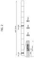
- FIG. 2 is a diagram showing the structure of a radio frame in the 3GPP LTE.
- the section 6 of 3GPP TS 36.211 V8.5.0 (2008-12) "Evolved Universal Terrestrial Radio Access (E-UTRA); Physical Channels and Modulation (Release 8)" may be incorporated herein by reference.
- a radio frame consists of 10 subframes indexed with 0 to 9.
- One subframe consists of 2 slots.
- a time required for transmitting one subframe is defined as a transmission time interval (TTI).
- TTI transmission time interval
- one subframe may have a length of 1 millisecond (ms), and one slot may have a length of 0.5 ms.
- One slot may include a plurality of orthogonal frequency division multiplexing (OFDM) symbols in a time domain.
- OFDM orthogonal frequency division multiplexing
- the OFDM symbol is only for expressing one symbol period in the time domain, and there is no limitation in a multiple access scheme or terminologies.
- the OFDM symbol may also be referred to as another terminology such as a single carrier frequency division multiple access (SC-FDMA) symbol, a symbol period, etc.
- SC-FDMA single carrier frequency division multiple access
- one slot includes 7 OFDM symbols for example, the number of OFDM symbols included in one slot may vary depending on a length of a cyclic prefix (CP).
- CP cyclic prefix
- a resource block is a resource allocation unit, and includes a plurality of subcarriers in one slot. For example, if one slot includes 7 OFDM symbols in a time domain and an RB includes 12 subcarriers in a frequency domain, one RB can include 7x12 resource elements (REs).
- REs resource elements
- a primary synchronization signal is transmitted in last OFDM symbols of a 1st slot, i.e., a 1st slot of a 1st subframe (a subframe indexed with 0), and an 11th slot, i.e., a 1st slot of a 6th subframe (a subframe indexed with 5).
- the PSS is used to obtain OFDM symbol synchronization or slot synchronization, and is in association with a physical cell identify (ID).
- a primary synchronization code (PSC) is a sequence used for the PSS.
- a secondary synchronization signal includes a 1st SSS and a 2nd SSS.
- the 1st SSS and the 2nd SSS are transmitted in an OFDM symbol adjacent to an OFDM symbol in which the PSS is transmitted.
- the SSS is used to obtain frame synchronization.
- the SSS is used to obtain a cell ID together with the PSS.
- the 1st SSS and the 2nd SSS use different secondary synchronization codes (SSCs). If the 1st SSS and the 2nd SSS each include 31 subcarriers, sequences of two SSCs with a length of 31 are respectively used for the 1 st SSS and the 2nd SSS.
- a physical broadcast channel is transmitted in four preceding OFDM symbols of a 2nd slot of the 1st subframe.
- the PBCH carries necessary system information required by a UE to communicate with a BS.
- System information transmitted through the PBCH is referred to as a master information block (MIB).
- MIB master information block
- SIB system information transmitted through a physical downlink control channel
- SIB system information block
- the LTE classifies a physical channel into a data channel, i.e., a physical downlink shared channel (PDSCH) and a physical uplink shared channel (PUSCH), and a control channel, i.e., a physical downlink control channel (PDCCH) and a physical uplink control channel (PUCCH).
- a control channel i.e., a physical downlink control channel (PDCCH) and a physical uplink control channel (PUCCH).
- a downlink control channel i.e., a physical control format indicator channel (PCFICH) and a physical hybrid-ARQ indicator channel (PHICH).
- PCFICH physical control format indicator channel
- PHICH physical hybrid-ARQ indicator channel
- FIG. 3 is a diagram showing the structure of a downlink subframe in the 3GPP LTE.
- a subframe is divided into a control region and a data region in a time domain.
- the control region includes up to three preceding OFDM symbols of a 1st slot in the subframe. The number of OFDM symbols included in the control region may vary.
- a PDCCH is allocated to the control region, and a PDSCH is allocated to the data region.
- the DCI may include resource allocation of the PDSCH (this is referred to as a downlink grant), resource allocation of a PUSCH (this is referred to as an uplink grant), a set of transmit power control commands for individual UEs in any UE group and/or activation of a voice over Internet protocol (VoIP).
- DCI downlink control information
- the DCI may include resource allocation of the PDSCH (this is referred to as a downlink grant), resource allocation of a PUSCH (this is referred to as an uplink grant), a set of transmit power control commands for individual UEs in any UE group and/or activation of a voice over Internet protocol (VoIP).
- VoIP voice over Internet protocol
- a PCFICH transmitted in a 1st OFDM symbol in the subframe carries information regarding the number of OFDM symbols (i.e., a size of the control region) used for transmission of control channels in the subframe.
- a PHICH carries an acknowledgement (ACK)/not-acknowledgement (NACK) signal for uplink hybrid automatic repeat request (HARQ). That is, the ACK/NACK signal for uplink data transmitted by the UE is transmitted over the PHICH.
- ACK acknowledgement
- NACK not-acknowledgement
- FIG. 4 is a diagram showing an example of the resource mapping of PDCCHs.
- the section 6 of 3GPP TS 36.211 V8.5.0 (2008-12) may be incorporated herein by reference.
- R0 denotes a reference signal of a 1st antenna
- R1 denotes a reference signal of a 2nd antenna
- R2 denotes a reference signal of a 3rd antenna
- R3 denotes a reference signal of a 4th antenna.
- a control region in a subframe includes a plurality of control channel elements (CCEs).
- the CCE is a logical allocation unit used to provide the PDCCH with a coding rate depending on a radio channel state, and corresponds to a plurality of resource element groups (REGs).
- REGs resource element groups
- One REG (indicated by a quadruple in FIG. 4 ) includes 4 REs.
- One CCE includes 9 REGs.
- the number of CCEs used to configure one PDCCH may be selected from a set ⁇ 1, 2, 4, 8 ⁇ . Each element of the set ⁇ 1, 2, 4, 8 ⁇ is referred to as a CCE aggregation level.
- a control channel consisting of one or more CCEs performs interleaving in an REG unit, and is mapped to a physical resource after performing cyclic shift based on a cell identifier (ID).
- ID cell identifier
- FIG. 5 is an exemplary view showing the monitoring of PDCCHs.
- blind decoding is used to detect PDCCHs.
- Blind decoding is a method of demasking a specific ID for the CRC of a received PDCCH (referred to a candidate PDCCH) and checking CRC error in order to determine whether the corresponding PDCCH is its own control channel.
- a UE does not know that its own PDCCH is transmitted using which CCE aggregation level or which DCI format at which position within the control region.
- a plurality of PDCCHs can be transmitted in one subframe.
- a UE monitors the plurality of PDCCHs every subframe. Monitoring is an operation of attempting PDCCH decoding by the UE according to a format of the monitored PDCCH.
- the 3GPP LTE uses a search space to reduce an overload caused by blind decoding.
- the search space can be called a monitoring set of CCEs for PDCCHs.
- a UE monitors the PDCCHs within a corresponding search space.
- the search space is classified into a common search space and a UE-specific search space.
- the common search space is a space for searching for a PDCCH having common control information and consists of 16 CCEs indexed with 0 to 15.
- the common search space supports a PDCCH having a CCE aggregation level of ⁇ 4, 8 ⁇ .
- the UE-specific search space supports a PDCCH having a CCE aggregation level of ⁇ 1, 2, 4, 8 ⁇ .
- a method of transmitting an ACK/NACK signal through the PUCCH in the 3GPP LTE is described below.
- FIG. 6 is a diagram showing an example of an uplink subframe in the 3GPP LTE.
- the uplink subframe can be divided into a control region to which a physical uplink control channel (PUCCH) carrying uplink control information is allocated and a data region to which a physical uplink shared channel (PUSCH) carrying uplink data is allocated.
- a PUCCH for a UE is allocated in a pair of resource blocks in a subframe. Resources blocks belonging to the resource block-pair occupy different subcarriers in a first slot and a second slot.
- m is a position index indicating a logical frequency region position of the resource block pair, allocated to PUCCHs within the uplink subframe.
- FIG. 6 shows that resource blocks having the same m value occupy different subcarriers in the two slots.
- a PUCCH supports a multiple formats. PUCCHs having different numbers of bits per subframe can be used in accordance with a modulation scheme dependent on a PUCCH format.
- the table 1 shows an example of modulation schemes and the number of bits per subframe according to PUCCH formats.
- the PUCCH format 1 is used to transmit an SR (Scheduling Request), the PUCCH formats 1a/1b are used to transmit an ACK/NACK signal for an HARQ, the PUCCH format 2 is used to transmit a CQI, and each of the PUCCH formats 2a/2b is used to simultaneously transmit a CQI and an ACK/NACK signal.
- the PUCCH formats 1a/1b are used, but when only the SR is transmitted in a subframe, the PUCCH format 1 is used.
- the PUCCH format 1 is used.
- the ACK/NACK signal modulated in resources to which the SR has been allocated is transmitted.
- Each of all the PUCCH formats uses the cyclic shift (CS) of a sequence in each OFDM symbol.
- the cyclic-shifted sequence is generated by cyclically shifting a base sequence by a specific CS amount.
- the specific CS amount is indicated by a CS index.
- r u (n) e jb n ⁇ / 4
- u indicates a root index
- n indicates an element index where 0 ⁇ n ⁇ N-1
- N indicates the length of the base sequence.
- b(n) is defined in 3GPP TS 36.211 V8.5.0 (2008-12).
- the length of the base sequence is equal to the number of elements included in the base sequence.
- ⁇ can be determined based on a cell ID (identifier) or a slot number within a radio frame. Assuming that the base sequence is mapped to one resource block in the frequency domain, the length of the base sequence N is 12 because one resource block includes 12 subcarriers.
- a different base sequence can be defined on the basis of a different root index.
- available CS indices of the base sequence refer to CS indices that can be derived from the base sequence on the basis of a CS interval. For example, assuming that the length of the base sequence is 12 and the CS interval is 1, a total number of available CS indices of the base sequence is 12. Assuming that the length of the base sequence is 12 and the CS interval is 2, the number of available CS indices of the base sequence is 6.
- PUCCH format 1 A method of transmitting the HARQ ACK/NACK signal in the PUCCH formats 1/1a/1b (hereinafter collectively referred to as a PUCCH format 1) is described below.
- FIG. 7 is a diagram showing the PUCCH format 1 in a normal CP in the 3GPP LTE.
- FIG. 8 is a diagram showing the PUCCH format 1 in an extended CP in the 3GPP LTE.
- the normal CP and the extended CP have different positions and different numbers of reference signals (RSs) because they include different numbers of OFDM symbols in one slot, but have the same ACK/NACK transmission structure.
- RSs reference signals
- a modulation symbol d(0) is generated by modulating an 1-bit ACK/NACK signal through BPSK (Binary Phase Shift Keying) or a 2-bit ACK/NACK signal through QPSK (Quadrature Phase Shift Keying).
- BPSK Binary Phase Shift Keying
- QPSK Quadrature Phase Shift Keying
- one slot includes 5 OFDM symbols for transmitting the ACK/NACK signal.
- One subframe includes 10 OFDM symbols for transmitting the ACK/NACK signal.
- the 1-dimensional spread sequence can be spread using an orthogonal sequence.
- Index (i) [w i (0), w i (1), w i (2), w i (3)] 0 [ +1, +1, +1, +1 ] 1 [ +1, -1, +1, -1 ] 2 [ +1, -1, -1, +1 ]
- a different spreading factor can be used for each slot.
- the last OFDM symbol within a subframe is used in order to transmit an SRS (sounding reference signal).
- SRS sounding reference signal
- 2-dimensional spread sequences s(0), s(1),..., s(9) can be expressed as follows:
- ⁇ s(0), s(1),..., s(9) ⁇ ⁇ wi(0)m(0), wi(1)m(1), wi(2)m(2), wi(3)m(3), wi(4)m(4), wi(0)m(5), wi(1)m(7), wi(2)m(8), wi(3)m(9) ⁇ .
- the 2-dimensional spread sequences ⁇ s(0), s(1),..., s(9) ⁇ are subject to IFFT and then transmitted through corresponding resource blocks. Accordingly, the ACK/NACK signal is transmitted on the PUCCH.
- the orthogonal sequence index i, the CS index I cs , and the resource block index m are parameters necessary to constitute a PUCCH and also resources used to distinguish PUCCHs (or UEs) from each other. Assuming that the number of available CSs is 12 and the number of available orthogonal sequence indices is 3, PUCCHs for a total of 36 UE can be multiplexed to one resource block.
- n (1) PUCCH n CCE +N (1) PUCCH .
- n CCE is the number of first CCEs used to transmit a corresponding DCI (i.e., the allocation of downlink resources used to receive downlink data corresponding to an ACK/NACK signal)
- n (1) PUCCH is a parameter that a BS informs the UE through an upper layer message.
- resources used to transmit a PUCCH are implicitly determined depending on the resources of a corresponding PDCCH. This is because a UE does not separately inform a BS of resources used to transmit a PUCCH for an ACK/NACK signal, but indirectly informs the BS of resources used for a PDCCH used to transmit downlink data.
- FIG. 9 is a diagram showing an example in which an HARQ is performed.
- a UE monitors PDCCHs and receives a PDCCH 501, including a downlink grant, in an n-th subframe.
- the UE receives a downlink transport block through a PDSCH 502 indicated by the downlink grant.
- the UE transmits an ACK/NACK signal for the downlink transport block on the PUCCH 511 in an (n+4)th subframe.
- the ACK/NACK signal becomes an ACK signal if the downlink transport block is successfully decoded and a NACK signal if the downlink transport block is unsuccessfully decoded.
- a BS can retransmit the downlink transport block until the reception of an ACK signal or a maximum number of retransmissions.
- uplink transmit power in the 3GPP LTEE is disclosed.
- P PUSCH min P CMAX , 10 log 10 M PUSCH i + P O_PUSCH j + ⁇ j PL + ⁇ TF i + f i
- P CMAX is the configured UE transmitted power
- M PUSCH (i) is the bandwidth of the PUSCH resource assignment expressed in number of resource blocks valid for subframe i.
- ⁇ (j) is a specific parameter provided by higher layers.
- PL is the downlink pathloss estimate calculated in the UE.
- ⁇ TF (i) is a UE specific parameter.
- f(i) is a UE specific value obtained from a transmit power control (TPC) command.
- P PUSCH min P CMAX , P O_PUCCH + PL + h n CQI , n HARQ + ⁇ F_PUCCH F + g i
- P CMAX and PL are same as the equation 3
- P 0_PUCCH is a parameter composed of the sum of a cell specific parameter P 0_NOMINAL-PUCCH provided by higher layers and a UE specific component P 0_UE_PUCCH provided by higher layers.
- h(n CQI , n HARQ ) is a PUCCH format dependent value.
- ⁇ F_PUCCH (F) is a parameter provided by higher layers.
- g(i) is a UE specific value obtained from a transmit power control (TPC) command.
- FIG. 10 is a diagram showing an example in which an ACK/NACK signal is transmitted via a multi-antenna.
- the time, frequency, and/or code resources used to transmit an ACK/NACK signal are referred to as ACK/NACK resources or PUCCH resources.
- the index of an ACK/NACK resource (also referred to as an ACK/NACK resource index or a PUCCH index) necessary to transmit the ACK/NACK signal on PUCCHs can be expressed into at least any one of the orthogonal sequence index i, the CS index I cs , the resource block index m, and indices for finding the three indices.
- the ACK/NACK resource can include at least any one of an orthogonal sequence, a CS, a resource block, and a combination of them.
- the ACK/NACK resource index is illustrated to be the above resource index n (1) PUCCH in order to clarify the description, the configuration or expression of the ACK/NACK resource is not limited.
- a modulation symbol s1 of an ACK/NACK signal is transmitted through a first antenna 601 using a first ACK/NACK resource and transmitted through a second antenna 602 using second ACK/NACK resources.
- a first orthogonal sequence index I 1 , a first CS index I cs1 , and a first resource block index m 1 are determined based on a first ACK/NACK resource index, and a first PUCCH is configured based on the determined indices.
- a second orthogonal sequence index i 2 , a second CS index I cs2 , and a second resource block index m 2 are determined based on a second ACK/NACK resource index, and a second PUCCH is configured based on the determined indices.
- the modulation symbol s1 is transmitted through the first antenna 601 on the first PUCCH and transmitted through the second antenna 602 on the second PUCCH.
- a single ACK/NACK resource is determined on the basis of resources used to transmit PDCCHs. More specifically, a single resource index (i.e., an index of the ACK/NACK resources) is determined on the basis of the lowest CCE index used to transmit a PDCCH.
- two ACK/NACK resources are needed to implement the example of FIG. 10 . This means that a plurality of ACK/NACK resources has to be allocated for multiple antenna transmission.
- FIG. 11 is a diagram showing a method of determining a plurality of resources.
- a first ACK/NACK resources are determined like the conventional 3GPP LTE, but a second ACK/NACK resources are determined on the basis of a CCE index next to the lowest CCE index.
- the CCE index next to the lowest CCE index may be set to 0 by using cyclic shift.
- N CCE is the total number of CCEs.
- the second ACK/NACK resource index P2 is illustrated to be determined on the basis of an index subsequent to the lowest CCE index, the second ACK/NACK resource index P2 may be determined using (n CCE +b)+N (1) PUCCH , more generally.
- b is a positive or negative integer.
- the wireless apparatus Even if a wireless apparatus supports multiple-antenna transmission, the multiple-antenna transmission cannot always be used. Due to any reason such as non-allocation of resources, etc., the wireless apparatus has to be able to dynamically perform switching between multiple-antenna transmission and single-antenna transmission.
- a UE obtains only a first ACK/NACK resource and cannot obtain a second ACK/NACK resource. If only one ACK/NACK resource is obtained, the UE can transmit an ACK/NACK signal through one antenna by using one ACK/NACK resource. That is, multiple-antenna transmission using two antennas is switched to single-antenna transmission.
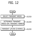
- FIG. 12 is a flowchart showing a transmission power control method according to an embodiment of the present invention.
- a UE selects one transmit mode among a plurality of transmit modes (step S1210).
- the transmit mode is an uplink transmit mode of the UE using multiple antennas or a single antenna.
- Multiple-antenna transmission can be classified according to the number of antennas in use. For example, if up to 4 antennas are supported, the UE can dynamically switch the multiple-antenna transmit mode using two or more antennas and the single-antenna transmit mode using one antenna.
- the multiple-antenna transmission may use different transmit modes when the number of antennas is 2, 3, and 4.
- the UE can determine the transmit mode by the instruction of a BS.
- the BS can instruct the multiple-antenna transmit mode or the single-antenna transmit mode to the UE by using a higher-layer message or a PDCCH.
- the UE can determine the transmit mode on the basis of a resource (i.e., a PUCCH resource) allocated to uplink transmission. If the number of PUCCH resources allocated to the UE is greater than 1, the multiple-antenna transmit mode can be determined as the transmit mode, and if the number of PUCCH resources is 1, the single-antenna transmit mode can be determined as the transmit mode.
- a resource i.e., a PUCCH resource allocated to uplink transmission. If the number of PUCCH resources allocated to the UE is greater than 1, the multiple-antenna transmit mode can be determined as the transmit mode, and if the number of PUCCH resources is 1, the single-antenna transmit mode can be determined as the transmit mode.
- the UE determines transmit power of an uplink channel on the basis of the selected transmit mode (step S1220).
- the transmit power can be determined on the basis of a transmit power offset ⁇ (M) depending on the transmit mode.
- M denotes the transmit mode.
- the UE determines one transmit power offset among ⁇ (1), ⁇ (2), ⁇ (3), and ⁇ (4) according to the selected transmit mode.
- the UE determines the transmit power offset ⁇ (M) according to the transmit mode, and can add the determined transmit power offset to the transmit power of the uplink channel.
- transmit power P PUSCH for PUSCH transmission of Equation 3 can be modified as follows.
- P PUSCH min P CMAX , 10 log 10 M PUSCH i + P O_PUSCH j + ⁇ j L + ⁇ TF i + ⁇ M + f i
- transmit power P PUCCH for PUCCH transmission of Equation 4 can be modified as follows.
- P PUSCH min P CMAX , P O_PUCCH + PL + h n CQI , n HARQ + ⁇ F_PUCCH F + ⁇ M + g i
- the transmit power offset ⁇ (M) can be included in a UE-specific parameter (e.g., ⁇ TF (i), f(i), ⁇ F_PUCCH (F), and g(i)) used to calculate the transmit power.
- a UE-specific parameter e.g., ⁇ TF (i), f(i), ⁇ F_PUCCH (F), and g(i)
- the UE transmits the uplink channel by using the transmit power (step S1230).
- the ACK/NACK signal can be transmitted as shown in FIG. 10 .
- transmit power of each transmit antenna is X dBm. In this case, total transmit power is X+3 dBm.
- the UE can be switched to the single-antenna mode.
- the transmit power maintains the previous transmit power X dBm
- link capability may deteriorate.
- the previous transmit power X dBm is designed by considering a transmit diversity gain. This is because the transmit diversity gain decreases in the single-antenna transmission.
- the proposed method allows the UE to control the transmit power of the uplink channel according to the transmit mode.
- ⁇ (M) The less the number of antennas in use, the greater the transmit power offset ⁇ (M) can be set.
- ⁇ (2) can be set to 0, and ⁇ (1) can be set to K (where K is a positive integer).
- the transmit power offset ⁇ (M) can be pre-defined.
- the BS can send information for obtaining the transmit power offset ⁇ (M) to the UE.
- the BS can send a transmit power offset depending on each transmit mode, or send a difference between a transmit power offset of one transmit mode and a transmit power offset of the remaining transmit modes.
- the information can be transmitted by using system information, an RRC message, a MAC message, or a PDCCH.
- the transmit power offset ⁇ (M) can vary depending on a PUCCH format. This is because a compensation value of the transmit power may differ since the transmit diversity gain varies depending on the PUCCH format.
- FIG. 13 is a block diagram showing a wireless apparatus for implementing an embodiment of the present invention.
- the wireless apparatus may be a part of a UE and implements the embodiment of FIG. 12 .
- a wireless apparatus 1300 includes a data processor 1310, a transmit power controller 1320, a transceiver 1330, and a plurality of antennas 1340.
- the data processor 1310 implements encoding/decoding and modulation/demodulation of traffic data and/or control signals (e.g., CQI and ACK/NACK).
- traffic data and/or control signals e.g., CQI and ACK/NACK.
- the transmit power controller 1320 controls transmit power of an uplink channel. As shown in the embodiment of FIG. 12 , the transmit power controller 1320 can determine a transmit mode, and can determine the transmit power of the uplink channel on the basis of the transmit mode.
- the transceiver 1330 transmits the traffic data and/or the control signals through one or more antennas 1340 on the uplink channel by using the transmit power.
- the data processor 1310, the transmit power controller 1320, and the transceiver 1330 can be implemented by one processor, chipset, or logical circuit.
- the antenna is also referred to as an antenna port, and may be a physical antenna or a logical antenna.
- One logical antenna may include one or more physical antennas.
- aspects of the invention include a method of controlling a transmit power in a wireless communication system, the method comprising: selecting one transmit mode among a plurality of transmit modes; determining the transmit power on the basis of the selected transmit mode; and transmitting an uplink channel by using the transmit power.
- Some aspects include the above method of controlling a transmit power in a wireless communication system, wherein the plurality of transmit modes comprise a multiple-antenna transmit mode and a single-antenna transmit mode.
- Some aspects include the above method of controlling a transmit power in a wireless communication system, wherein the plurality of transmit modes are determined based on the number of transmit antennas.
- Some aspects include the above method of controlling a transmit power in a wireless communication system, wherein the uplink channel is a physical uplink shared channel (PUSCH) or a physical uplink control channel (PUCCH).
- PUSCH physical uplink shared channel
- PUCCH physical uplink control channel
- Some aspects include the above method of controlling a transmit power in a wireless communication system, wherein the step of determining of the transmit power on the basis of the selected transmit mode comprises adding a transmit power control value corresponding to the selected transmit mode to transmit power for the uplink channel.
- Some aspects include the above method of controlling a transmit power in a wireless communication system, wherein one of transmit mode is selected among the plurality of transmit modes on the basis of a resource allocated to the uplink channel.
- Some aspects include the above method of controlling a transmit power in a wireless communication system, wherein, if the number of resources allocated to the uplink channel is greater than 1, a multiple-antenna transmission mode is selected, and if the number of resources allocated to the uplink channel is 1, a single-antenna transmission mode is selected.
- Some aspects include the above method of controlling a transmit power in a wireless communication system, wherein a resource allocated to the uplink channel is obtained based on a resource used to transmit a downlink control channel.
- a wireless apparatus comprising: a plurality of antennas; a transceiver configured for transmitting an uplink channel through the plurality of antennas by using transmit power; and a transmit power controller configured for selecting one transmit mode among a plurality of transmit modes and determining the transmit power on the basis of the selected transmit mode.
- Some aspects include the above wireless apparatus, wherein the plurality of transmit modes comprise a multiple-antenna transmit mode and a single-antenna transmit mode.
- Some aspects include the above wireless apparatus, wherein the transmit power controller selects one transmit mode among the plurality of transmit modes on the basis of a resource allocated to the uplink channel.
Abstract
Description
- The present invention relates to wireless communication, and more particularly, to a method and apparatus for controlling transmit power in a wireless communication system.
- Long term evolution (LTE) based on 3rd generation partnership project (3GPP) technical specification (TS)
release 8 is a promising next-generation mobile communication standard. - As disclosed in 3GPP TS 36.211 V8.5.0 (2008-12) "Evolved Universal Terrestrial Radio Access (E-UTRA); Physical Channels and Modulation (Release 8)", a physical channel of the LTE can be classified into a data channel, i.e., a physical downlink shared channel (PDSCH) and a physical uplink shared channel (PUSCH), and a control channel, i.e., a physical downlink control channel (PDCCH), a physical control format indicator channel (PCFICH), a physical hybrid-ARQ indicator channel (PHICH), and a physical uplink control channel (PUCCH).
- A PDCCH (i.e., a downlink control channel) carries a downlink grant for receiving the PDSCH of a UE (UE) and an uplink grant for transmitting the PUSCH of a UE. A PUCCH (i.e., an uplink control channel) carries an uplink control signal (e.g., ACK (positive-acknowledgement)/NACK (negative-acknowledgement) signals for a HARQ), a CQI (Channel Quality Indicator) indicating the condition of a downlink channel, an SR (Scheduling Request) for requesting the allocation of radio resources for uplink transmission, and so on.
- To guarantee a higher data rate, a technique using a multi-antenna has been introduced.
- Through transmit diversity and spatial multiplexing, multiple antenna transmission can achieve higher link performance compared to single antenna transmission.
- The conventional 3GP LTE does not support multiple antenna transmission in uplink. However, as a next generation communication system employs the multiple antenna uplink, uplink transmit power is needed to consider multiple antenna transmission.
- The present invention provides a method and apparatus for performing an HARQ using a plurality of resources and a plurality of antennas.
- In an aspect, a method of controlling a transmit power in a wireless communication system is provided. The method includes selecting one transmit mode among a plurality of transmit modes, determining the transmit power on the basis of the selected transmit mode, and transmitting an uplink channel by using the transmit power.
- The plurality of transmit modes may include a multiple-antenna transmit mode and a single-antenna transmit mode.
- The plurality of transmit modes may be determined based on the number of transmit antennas.
- The uplink channel may be a physical uplink shared channel (PUSCH) or a physical uplink control channel (PUCCH).
- The step of determining of the transmit power on the basis of the selected transmit mode may include adding a transmit power control value corresponding to the selected transmit mode to transmit power for the uplink channel.
- One of transmit mode may be selected among the plurality of transmit modes on the basis of a resource allocated to the uplink channel.
- If the number of resources allocated to the uplink channel is greater than 1, a multiple-antenna transmission mode may be selected, and if the number of resources allocated to the uplink channel is 1, a single-antenna transmission mode may be selected.
- A resource allocated to the uplink channel may be obtained based on a resource used to transmit a downlink control channel.
- In another aspect, a wireless apparatus includes a plurality of antennas, a transceiver configured for transmitting an uplink channel through the plurality of antennas by using transmit power, and a transmit power controller configured for selecting one transmit mode among a plurality of transmit modes and determining the transmit power on the basis of the selected transmit mode.
- As a user equipment switches a transmit mode, a transmit power can be adjusted. Therefore, link performance can be improved.
-
-
FIG. 1 is a diagram showing a wireless communication system. -
FIG. 2 is a diagram showing the structure of a radio frame in the 3GPP LTE. -
FIG. 3 is a diagram showing the structure of a downlink subframe in the 3GPP LTE. -
FIG. 4 is a diagram showing an example of the resource mapping of PDCCHs. -
FIG. 5 is an exemplary view showing the monitoring of PDCCHs. -
FIG. 6 is a diagram showing an example of an uplink subframe in the 3GPP LTE. -
FIG. 7 is a diagram showing aPUCCH format 1 in a normal CP in the 3GPP LTE. -
FIG. 8 is a diagram showing aPUCCH format 1 in an extended CP in the 3GPP LTE. -
FIG. 9 is a diagram showing an example in which an HARQ is performed. -
FIG. 10 is a diagram showing an example in which an ACK/NACK signal is transmitted in a multi-antenna. -
FIG. 11 is a diagram showing a method of determining a plurality of resources. -
FIG. 12 is a flowchart showing a transmission power control method according to an embodiment of the present invention. -
FIG. 13 is a block diagram showing a wireless apparatus for implementing an embodiment of the present invention. -
FIG. 1 is a diagram showing a wireless communication system. Awireless communication system 10 includes one or more base stations (BSs) 11. Each of theBSs 11 provides communication services to a specific geographical area (in general referred to as a cell) 15a, 15b, or 15c. Each of the cells can be divided into a plurality of regions (referred to as sectors). - A user equipment (UE) 12 may be fixed or mobile, and may be referred to as another terminology, such as a mobile station (MS), a mobile terminal (MT), a user terminal (UT), a subscriber station (SS), a wireless device, a personal digital assistant (PDA), a wireless modem, a handheld device, etc.
- The
BS 11 is generally a fixed station that communicates with the UE 12 and may be referred to as another terminology, such as an evolved node-B (eNB), a base transceiver system (BTS), an access point, etc. - Hereinafter, downlink implies communication from the BS to the UE, and uplink implies communication from the UE to the BS. In the downlink, a transmitter may be a part of the BS, and a receiver may be a part of the MS. In the uplink, the transmitter may be a part of the UE, and the receiver may be a part of the BS.
-
FIG. 2 is a diagram showing the structure of a radio frame in the 3GPP LTE. Thesection 6 of 3GPP TS 36.211 V8.5.0 (2008-12) "Evolved Universal Terrestrial Radio Access (E-UTRA); Physical Channels and Modulation (Release 8)" may be incorporated herein by reference. A radio frame consists of 10 subframes indexed with 0 to 9. One subframe consists of 2 slots. A time required for transmitting one subframe is defined as a transmission time interval (TTI). For example, one subframe may have a length of 1 millisecond (ms), and one slot may have a length of 0.5 ms. - One slot may include a plurality of orthogonal frequency division multiplexing (OFDM) symbols in a time domain. Since the 3GPP LTE uses orthogonal frequency division multiple access (OFDMA) in a downlink, the OFDM symbol is only for expressing one symbol period in the time domain, and there is no limitation in a multiple access scheme or terminologies. For example, the OFDM symbol may also be referred to as another terminology such as a single carrier frequency division multiple access (SC-FDMA) symbol, a symbol period, etc.
- Although it is described that one slot includes 7 OFDM symbols for example, the number of OFDM symbols included in one slot may vary depending on a length of a cyclic prefix (CP). According to 3GPP TS 36.211 V8.5.0 (2008-12), in case of a normal CP, one subframe includes 7 OFDM symbols, and in case of an extended CP, one subframe includes 6 OFDM symbols.
- A resource block (RB) is a resource allocation unit, and includes a plurality of subcarriers in one slot. For example, if one slot includes 7 OFDM symbols in a time domain and an RB includes 12 subcarriers in a frequency domain, one RB can include 7x12 resource elements (REs).
- A primary synchronization signal (PSS) is transmitted in last OFDM symbols of a 1st slot, i.e., a 1st slot of a 1st subframe (a subframe indexed with 0), and an 11th slot, i.e., a 1st slot of a 6th subframe (a subframe indexed with 5). The PSS is used to obtain OFDM symbol synchronization or slot synchronization, and is in association with a physical cell identify (ID). A primary synchronization code (PSC) is a sequence used for the PSS. There are three PSCs in the 3GPP LTE. One of the three PSCs is transmitted using the PSS according to a cell ID. The same PSC is used for each of the last OFDM symbols of the 1st slot and the 11th slot.
- A secondary synchronization signal (SSS) includes a 1st SSS and a 2nd SSS. The 1st SSS and the 2nd SSS are transmitted in an OFDM symbol adjacent to an OFDM symbol in which the PSS is transmitted. The SSS is used to obtain frame synchronization. The SSS is used to obtain a cell ID together with the PSS. The 1st SSS and the 2nd SSS use different secondary synchronization codes (SSCs). If the 1st SSS and the 2nd SSS each include 31 subcarriers, sequences of two SSCs with a length of 31 are respectively used for the 1 st SSS and the 2nd SSS.
- A physical broadcast channel (PBCH) is transmitted in four preceding OFDM symbols of a 2nd slot of the 1st subframe. The PBCH carries necessary system information required by a UE to communicate with a BS. System information transmitted through the PBCH is referred to as a master information block (MIB). In comparison thereto, system information transmitted through a physical downlink control channel (PDCCH) is referred to as a system information block (SIB).
- As disclosed in 3GPP TS 36.211 V8.5.0 (2008-12), the LTE classifies a physical channel into a data channel, i.e., a physical downlink shared channel (PDSCH) and a physical uplink shared channel (PUSCH), and a control channel, i.e., a physical downlink control channel (PDCCH) and a physical uplink control channel (PUCCH). Further, there is a downlink control channel, i.e., a physical control format indicator channel (PCFICH) and a physical hybrid-ARQ indicator channel (PHICH).
-
FIG. 3 is a diagram showing the structure of a downlink subframe in the 3GPP LTE. A subframe is divided into a control region and a data region in a time domain. The control region includes up to three preceding OFDM symbols of a 1st slot in the subframe. The number of OFDM symbols included in the control region may vary. A PDCCH is allocated to the control region, and a PDSCH is allocated to the data region. - Control information transmitted through the PDCCH is referred to as downlink control information (DCI). The DCI may include resource allocation of the PDSCH (this is referred to as a downlink grant), resource allocation of a PUSCH (this is referred to as an uplink grant), a set of transmit power control commands for individual UEs in any UE group and/or activation of a voice over Internet protocol (VoIP).
- A PCFICH transmitted in a 1st OFDM symbol in the subframe carries information regarding the number of OFDM symbols (i.e., a size of the control region) used for transmission of control channels in the subframe.
- A PHICH carries an acknowledgement (ACK)/not-acknowledgement (NACK) signal for uplink hybrid automatic repeat request (HARQ). That is, the ACK/NACK signal for uplink data transmitted by the UE is transmitted over the PHICH.
-
FIG. 4 is a diagram showing an example of the resource mapping of PDCCHs. Thesection 6 of 3GPP TS 36.211 V8.5.0 (2008-12) may be incorporated herein by reference. R0 denotes a reference signal of a 1st antenna, R1 denotes a reference signal of a 2nd antenna, R2 denotes a reference signal of a 3rd antenna, and R3 denotes a reference signal of a 4th antenna. - A control region in a subframe includes a plurality of control channel elements (CCEs). The CCE is a logical allocation unit used to provide the PDCCH with a coding rate depending on a radio channel state, and corresponds to a plurality of resource element groups (REGs). According to an association relation of the number of CCEs and the coding rate provided by the CCEs, a PDCCH format and a possible number of bits of the PDCCH are determined.
- One REG (indicated by a quadruple in
FIG. 4 ) includes 4 REs. One CCE includes 9 REGs. The number of CCEs used to configure one PDCCH may be selected from a set {1, 2, 4, 8}. Each element of the set {1, 2, 4, 8} is referred to as a CCE aggregation level. - A control channel consisting of one or more CCEs performs interleaving in an REG unit, and is mapped to a physical resource after performing cyclic shift based on a cell identifier (ID).
-
FIG. 5 is an exemplary view showing the monitoring of PDCCHs. For the monitoring of PDCCHs, reference can be made tosection 9 of 3GPP TS 36.213 V8.5.0 (2008-12). In the 3GPP LTE, blind decoding is used to detect PDCCHs. Blind decoding is a method of demasking a specific ID for the CRC of a received PDCCH (referred to a candidate PDCCH) and checking CRC error in order to determine whether the corresponding PDCCH is its own control channel. A UE does not know that its own PDCCH is transmitted using which CCE aggregation level or which DCI format at which position within the control region. - A plurality of PDCCHs can be transmitted in one subframe. A UE monitors the plurality of PDCCHs every subframe. Monitoring is an operation of attempting PDCCH decoding by the UE according to a format of the monitored PDCCH.
- The 3GPP LTE uses a search space to reduce an overload caused by blind decoding. The search space can be called a monitoring set of CCEs for PDCCHs. A UE monitors the PDCCHs within a corresponding search space.
- The search space is classified into a common search space and a UE-specific search space. The common search space is a space for searching for a PDCCH having common control information and consists of 16 CCEs indexed with 0 to 15. The common search space supports a PDCCH having a CCE aggregation level of {4, 8}. The UE-specific search space supports a PDCCH having a CCE aggregation level of {1, 2, 4, 8}.
- A method of transmitting an ACK/NACK signal through the PUCCH in the 3GPP LTE is described below.
-
FIG. 6 is a diagram showing an example of an uplink subframe in the 3GPP LTE. The uplink subframe can be divided into a control region to which a physical uplink control channel (PUCCH) carrying uplink control information is allocated and a data region to which a physical uplink shared channel (PUSCH) carrying uplink data is allocated. A PUCCH for a UE is allocated in a pair of resource blocks in a subframe. Resources blocks belonging to the resource block-pair occupy different subcarriers in a first slot and a second slot. InFIG. 6 , m is a position index indicating a logical frequency region position of the resource block pair, allocated to PUCCHs within the uplink subframe.FIG. 6 shows that resource blocks having the same m value occupy different subcarriers in the two slots. - In accordance with 3GPP TS 36.211 V8.5.0 (2008-12), a PUCCH supports a multiple formats. PUCCHs having different numbers of bits per subframe can be used in accordance with a modulation scheme dependent on a PUCCH format.
- The table 1 shows an example of modulation schemes and the number of bits per subframe according to PUCCH formats.
[Table 1] PUCCH Format Modulation Scheme Number of Bits per subframe 1 N/A N/ A 1a BPSK 1 1b QPSK 2 2 QPSK 20 2a QPSK+BPSK 21 2b QPSK+BPSK 22 - The
PUCCH format 1 is used to transmit an SR (Scheduling Request), the PUCCH formats 1a/1b are used to transmit an ACK/NACK signal for an HARQ, thePUCCH format 2 is used to transmit a CQI, and each of the PUCCH formats 2a/2b is used to simultaneously transmit a CQI and an ACK/NACK signal. When only the ACK/NACK signal is transmitted in a subframe, the PUCCH formats 1a/1b are used, but when only the SR is transmitted in a subframe, thePUCCH format 1 is used. When the SR and the ACK/NACK signal are simultaneously transmitted, thePUCCH format 1 is used. The ACK/NACK signal modulated in resources to which the SR has been allocated is transmitted. - Each of all the PUCCH formats uses the cyclic shift (CS) of a sequence in each OFDM symbol. The cyclic-shifted sequence is generated by cyclically shifting a base sequence by a specific CS amount. The specific CS amount is indicated by a CS index.
- An example in which the base sequence ru(n) is defined is shown as:

where u indicates a root index, n indicates an element index where 0≤n≤N-1, and N indicates the length of the base sequence. b(n) is defined in 3GPP TS 36.211 V8.5.0 (2008-12). - The length of the base sequence is equal to the number of elements included in the base sequence. µ can be determined based on a cell ID (identifier) or a slot number within a radio frame. Assuming that the base sequence is mapped to one resource block in the frequency domain, the length of the base sequence N is 12 because one resource block includes 12 subcarriers. A different base sequence can be defined on the basis of a different root index.
- A cyclic-shifted sequence r(n, Ics) can be generated by cyclically shifting a base sequence r(n) as shown:

where Ics is a CS index indicating the CS amount (0≤Ics≤N-1). - Hereinafter, available CS indices of the base sequence refer to CS indices that can be derived from the base sequence on the basis of a CS interval. For example, assuming that the length of the base sequence is 12 and the CS interval is 1, a total number of available CS indices of the base sequence is 12. Assuming that the length of the base sequence is 12 and the CS interval is 2, the number of available CS indices of the base sequence is 6.
- A method of transmitting the HARQ ACK/NACK signal in the PUCCH formats 1/1a/1b (hereinafter collectively referred to as a PUCCH format 1) is described below.
-
FIG. 7 is a diagram showing thePUCCH format 1 in a normal CP in the 3GPP LTE.FIG. 8 is a diagram showing thePUCCH format 1 in an extended CP in the 3GPP LTE. The normal CP and the extended CP have different positions and different numbers of reference signals (RSs) because they include different numbers of OFDM symbols in one slot, but have the same ACK/NACK transmission structure. - A modulation symbol d(0) is generated by modulating an 1-bit ACK/NACK signal through BPSK (Binary Phase Shift Keying) or a 2-bit ACK/NACK signal through QPSK (Quadrature Phase Shift Keying).
- In the normal CP or the extended CP, one slot includes 5 OFDM symbols for transmitting the ACK/NACK signal. One subframe includes 10 OFDM symbols for transmitting the ACK/NACK signal. The modulation symbol d(0) is spread with a cyclic-shifted sequence r(n,Ics). Assuming 1-dimensional spread sequence corresponding to an (i+1)th OFDM symbol in a subframe is m(i), {m(0), m(1),..., m(9)} = {d(0)r(n,Ics), d(0)r(n,Ics), ..., d(0)r(n,Ics)}.
- To increase UE capacity, the 1-dimensional spread sequence can be spread using an orthogonal sequence.
- An orthogonal sequence wi(k), where i is a sequence index and 0≤k≤K-1, having a spreading factor K=4 may use the following sequence.
[Table 2] Index (i) [wi(0), wi(1), wi(2), wi(3)] 0 [ +1, +1, +1, +1 ] 1 [ +1, -1, +1, -1 ] 2 [ +1, -1, -1, +1 ] - The orthogonal sequence wi(k), where i is a sequence index and 0≤k≤K-1, having a spreading factor K=3 may use the following sequence.
[Table 3] Index (i) [ wi(0), wi(1), wi(2) ] 0 [ +1, +1, +1 ] 1 [ + 1, ej2π/3, ej4π/3 ] 2 [ +1, ej4π/3, ej2π/3 ] - A different spreading factor can be used for each slot. In the 3GPP LTE, the last OFDM symbol within a subframe is used in order to transmit an SRS (sounding reference signal). Here, in a PUCCH, a first slot uses the spreading factor K=4 and a second slot uses the spreading factor K=3.
- Accordingly, assuming that a certain orthogonal sequence index i is given, 2-dimensional spread sequences s(0), s(1),..., s(9) can be expressed as follows:
- {s(0), s(1),..., s(9)}={wi(0)m(0), wi(1)m(1), wi(2)m(2), wi(3)m(3), wi(4)m(4), wi(0)m(5), wi(1)m(7), wi(2)m(8), wi(3)m(9)}.
- The CS index Ics can vary depending on a slot number (ns) within a radio frame or a symbol index (ℓ) within a slot or both. Assuming that the first CS index is 0 and the value of a CS index is increased by 1 every OFDM symbol, {s(0), s(1),..., s(9)} = {wi(0)d(0)r(n,0), wi(1)d(1)r(n,1), ..., wi(3)d(9)r(n,9)}, as shown in
FIGs. 7 and8 . - The 2-dimensional spread sequences {s(0), s(1),..., s(9)} are subject to IFFT and then transmitted through corresponding resource blocks. Accordingly, the ACK/NACK signal is transmitted on the PUCCH.
- The orthogonal sequence index i, the CS index Ics, and the resource block index m are parameters necessary to constitute a PUCCH and also resources used to distinguish PUCCHs (or UEs) from each other. Assuming that the number of available CSs is 12 and the number of available orthogonal sequence indices is 3, PUCCHs for a total of 36 UE can be multiplexed to one resource block.
- In the 3GPP LTE, in order for a UE to acquire the above three parameters for constituting the PUCCH, a resource index n(1) PUCCH is defined. The resource index n(1) PUCCH = nCCE+N(1) PUCCH. Here, nCCE is the number of first CCEs used to transmit a corresponding DCI (i.e., the allocation of downlink resources used to receive downlink data corresponding to an ACK/NACK signal), and n(1) PUCCH is a parameter that a BS informs the UE through an upper layer message.
- Consequently, it can be said that resources used to transmit a PUCCH are implicitly determined depending on the resources of a corresponding PDCCH. This is because a UE does not separately inform a BS of resources used to transmit a PUCCH for an ACK/NACK signal, but indirectly informs the BS of resources used for a PDCCH used to transmit downlink data.
-
FIG. 9 is a diagram showing an example in which an HARQ is performed. A UE monitors PDCCHs and receives aPDCCH 501, including a downlink grant, in an n-th subframe. The UE receives a downlink transport block through aPDSCH 502 indicated by the downlink grant. - The UE transmits an ACK/NACK signal for the downlink transport block on the
PUCCH 511 in an (n+4)th subframe. The ACK/NACK signal becomes an ACK signal if the downlink transport block is successfully decoded and a NACK signal if the downlink transport block is unsuccessfully decoded. When the NACK signal is received, a BS can retransmit the downlink transport block until the reception of an ACK signal or a maximum number of retransmissions. - To constitute the
PUCCH 511, the UE uses resource allocation of thePDCCH 501. That is, the lowest CCE index used to transmit thePDCCH 501 becomes nCCE, and a resource index, such as n(1) PUCCH = nCCE+N(1) PUCCH, is determined. - Hereinafter, referring to
section 5 of 3GPP TS 36.213 V8.5.0 (2008-12), uplink transmit power in the 3GPP LTEE is disclosed. - The setting of the UE Transmit power PPUSCH for the PUSCH transmission in subframe i is defined by:

where PCMAX is the configured UE transmitted power, and MPUSCH(i) is the bandwidth of the PUSCH resource assignment expressed in number of resource blocks valid for subframe i. PO_PUSCH(j) is a parameter composed of the sum of a cell specific nominal component PO_NOMINAL_PUSCH(j) provided from higher layers for j=0 and 1 and a UE specific component Po_UE_PUSCH(j) provided by higher layers for j=0 and 1. α(j) is a specific parameter provided by higher layers. PL is the downlink pathloss estimate calculated in the UE. ΔTF(i) is a UE specific parameter. f(i) is a UE specific value obtained from a transmit power control (TPC) command. - The setting of the UE Transmit power PPUCCH for the PUCCH transmission in subframe i is defined by:

where PCMAX and PL are same as theequation 3, and P0_PUCCH is a parameter composed of the sum of a cell specific parameter P0_NOMINAL-PUCCH provided by higher layers and a UE specific component P0_UE_PUCCH provided by higher layers. h(nCQI, nHARQ) is a PUCCH format dependent value. ΔF_PUCCH(F) is a parameter provided by higher layers. g(i) is a UE specific value obtained from a transmit power control (TPC) command. - Hereinafter, multiple antenna transmission in uplink is disclosed.
-
FIG. 10 is a diagram showing an example in which an ACK/NACK signal is transmitted via a multi-antenna. - The time, frequency, and/or code resources used to transmit an ACK/NACK signal are referred to as ACK/NACK resources or PUCCH resources. As described above, the index of an ACK/NACK resource (also referred to as an ACK/NACK resource index or a PUCCH index) necessary to transmit the ACK/NACK signal on PUCCHs can be expressed into at least any one of the orthogonal sequence index i, the CS index Ics, the resource block index m, and indices for finding the three indices. The ACK/NACK resource can include at least any one of an orthogonal sequence, a CS, a resource block, and a combination of them.
- Although the ACK/NACK resource index is illustrated to be the above resource index n(1) PUCCH in order to clarify the description, the configuration or expression of the ACK/NACK resource is not limited.
- A modulation symbol s1 of an ACK/NACK signal is transmitted through a
first antenna 601 using a first ACK/NACK resource and transmitted through asecond antenna 602 using second ACK/NACK resources. - A first orthogonal sequence index I1, a first CS index Ics1, and a first resource block index m1 are determined based on a first ACK/NACK resource index, and a first PUCCH is configured based on the determined indices. A second orthogonal sequence index i2, a second CS index Ics2, and a second resource block index m2 are determined based on a second ACK/NACK resource index, and a second PUCCH is configured based on the determined indices. The modulation symbol s1 is transmitted through the
first antenna 601 on the first PUCCH and transmitted through thesecond antenna 602 on the second PUCCH. - Consequently, since the same ACK/NACK signal is transmitted through different antennas using different resources, transmit diversity gain can be obtained.
- In the conventional 3GPP LTE which only support single antenna transmission, a single ACK/NACK resource is determined on the basis of resources used to transmit PDCCHs. More specifically, a single resource index (i.e., an index of the ACK/NACK resources) is determined on the basis of the lowest CCE index used to transmit a PDCCH. This scheme
- However, two ACK/NACK resources are needed to implement the example of
FIG. 10 . This means that a plurality of ACK/NACK resources has to be allocated for multiple antenna transmission. -
FIG. 11 is a diagram showing a method of determining a plurality of resources. In this method, a first ACK/NACK resources are determined like the conventional 3GPP LTE, but a second ACK/NACK resources are determined on the basis of a CCE index next to the lowest CCE index. - It is assumed that a
CCE index 5 used to transmit a PDCCH for a downlink grant, from among CCE indices, is the lowest index. If the CCE aggregation level L is 1, a first ACK/NACK resource index P1 is determined on the basis of thelowest CCE index 5 as in the existing method, and a second ACK/NACK resource index P2 is determined on the basis of anindex 6 subsequent to thelowest CCE index 5. The same principle is applied to CCE aggregation levels L = 2, 4, and 8. - If the CCE index next to the lowest CCE index is larger than NCCE-1, the CCE index next to the lowest CCE index may be set to 0 by using cyclic shift. NCCE is the total number of CCEs.
- In other words, the first and second ACK/NACK resource indices P1 and P2 may respectively be defined as P1=nCCE+N(1) PUCCH and P2=(nCCE+1)+N(1) PUCCH, respectively, irrespective of their CCE aggregation levels.
- Although the second ACK/NACK resource index P2 is illustrated to be determined on the basis of an index subsequent to the lowest CCE index, the second ACK/NACK resource index P2 may be determined using (nCCE+b)+N(1) PUCCH, more generally. Here, b is a positive or negative integer.
- Now, the proposed uplink transmit power control will be described.
- Even if a wireless apparatus supports multiple-antenna transmission, the multiple-antenna transmission cannot always be used. Due to any reason such as non-allocation of resources, etc., the wireless apparatus has to be able to dynamically perform switching between multiple-antenna transmission and single-antenna transmission.
- In the example of
FIG. 11 , if aCCE index 6 is allocated to another UE, a UE obtains only a first ACK/NACK resource and cannot obtain a second ACK/NACK resource. If only one ACK/NACK resource is obtained, the UE can transmit an ACK/NACK signal through one antenna by using one ACK/NACK resource. That is, multiple-antenna transmission using two antennas is switched to single-antenna transmission. - When a transmit mode is switched, link capability may deteriorate if transmit power cannot be effectively controlled.
-
FIG. 12 is a flowchart showing a transmission power control method according to an embodiment of the present invention. - A UE selects one transmit mode among a plurality of transmit modes (step S1210). The transmit mode is an uplink transmit mode of the UE using multiple antennas or a single antenna.
- Transmission using the multiple antennas is referred to as a multiple-antenna transmit mode, and transmission using the single antenna is referred to as a single-antenna transmit mode. Multiple-antenna transmission can be classified according to the number of antennas in use. For example, if up to 4 antennas are supported, the UE can dynamically switch the multiple-antenna transmit mode using two or more antennas and the single-antenna transmit mode using one antenna. The multiple-antenna transmission may use different transmit modes when the number of antennas is 2, 3, and 4.
- The UE can determine the transmit mode by the instruction of a BS. The BS can instruct the multiple-antenna transmit mode or the single-antenna transmit mode to the UE by using a higher-layer message or a PDCCH.
- The UE can determine the transmit mode on the basis of a resource (i.e., a PUCCH resource) allocated to uplink transmission. If the number of PUCCH resources allocated to the UE is greater than 1, the multiple-antenna transmit mode can be determined as the transmit mode, and if the number of PUCCH resources is 1, the single-antenna transmit mode can be determined as the transmit mode.
- The UE determines transmit power of an uplink channel on the basis of the selected transmit mode (step S1220). The transmit power can be determined on the basis of a transmit power offset Δ(M) depending on the transmit mode. M denotes the transmit mode.
- For example, it is assumed that M=1 denotes a single-antenna transmit mode, M=2 denotes a multiple-antenna transmit mode using two antennas (or two resources), M=3 denotes a multiple-antenna transmit mode using three antennas (or three resources), and M=4 denotes a multiple-antenna transmit mode using four antennas (or four resources). The UE determines one transmit power offset among Δ(1), Δ(2), Δ(3), and Δ(4) according to the selected transmit mode.
- The UE determines the transmit power offset Δ(M) according to the transmit mode, and can add the determined transmit power offset to the transmit power of the uplink channel.
- When the transmit mode is considered, transmit power PPUSCH for PUSCH transmission of
Equation 3 can be modified as follows.
- In addition, transmit power PPUCCH for PUCCH transmission of
Equation 4 can be modified as follows.
- The above equation is for exemplary purposes only, and thus various modifications can be made by those ordinary skilled in the art. For example, the transmit power offset Δ(M) can be included in a UE-specific parameter (e.g., ΔTF(i), f(i), ΔF_PUCCH(F), and g(i)) used to calculate the transmit power.
- The UE transmits the uplink channel by using the transmit power (step S1230). When an ACK/NACK signal is transmitted using two antennas and two PUCCH resources, the ACK/NACK signal can be transmitted as shown in
FIG. 10 . - When the UE switches from the multiple-antenna transmit mode to the single-antenna transmit mode, if the UE performs single-antenna transmission while maintaining the same transmit power as that used in multiple-antenna transmission, link capability may deteriorate.
- For example, it is assumed that two PUCCH resources are allocated to the UE, and the UE transmits an ACK/NACK signal through two antennas in the multiple-antenna transmit mode. It is also assumed that transmit power of each transmit antenna is X dBm. In this case, total transmit power is X+3 dBm.
- When one PUCCH resource is allocated to the UE for a certain reason, the UE can be switched to the single-antenna mode. In this case, if the transmit power maintains the previous transmit power X dBm, link capability may deteriorate. The previous transmit power X dBm is designed by considering a transmit diversity gain. This is because the transmit diversity gain decreases in the single-antenna transmission.
- Therefore, the proposed method allows the UE to control the transmit power of the uplink channel according to the transmit mode.
- The less the number of antennas in use, the greater the transmit power offset Δ(M) can be set. For example, Δ(2) can be set to 0, and Δ(1) can be set to K (where K is a positive integer).
- The transmit power offset Δ(M) can be pre-defined.
- The BS can send information for obtaining the transmit power offset Δ(M) to the UE. The BS can send a transmit power offset depending on each transmit mode, or send a difference between a transmit power offset of one transmit mode and a transmit power offset of the remaining transmit modes. The information can be transmitted by using system information, an RRC message, a MAC message, or a PDCCH.
- The transmit power offset Δ(M) can vary depending on a PUCCH format. This is because a compensation value of the transmit power may differ since the transmit diversity gain varies depending on the PUCCH format.
-
FIG. 13 is a block diagram showing a wireless apparatus for implementing an embodiment of the present invention. The wireless apparatus may be a part of a UE and implements the embodiment ofFIG. 12 . - A
wireless apparatus 1300 includes adata processor 1310, a transmitpower controller 1320, atransceiver 1330, and a plurality ofantennas 1340. - The
data processor 1310 implements encoding/decoding and modulation/demodulation of traffic data and/or control signals (e.g., CQI and ACK/NACK). - The transmit
power controller 1320 controls transmit power of an uplink channel. As shown in the embodiment ofFIG. 12 , the transmitpower controller 1320 can determine a transmit mode, and can determine the transmit power of the uplink channel on the basis of the transmit mode. - The
transceiver 1330 transmits the traffic data and/or the control signals through one ormore antennas 1340 on the uplink channel by using the transmit power. - The
data processor 1310, the transmitpower controller 1320, and thetransceiver 1330 can be implemented by one processor, chipset, or logical circuit. - The antenna is also referred to as an antenna port, and may be a physical antenna or a logical antenna. One logical antenna may include one or more physical antennas.
- In view of the exemplary systems described herein, methodologies that may be implemented in accordance with the disclosed subject matter have been described with reference to several flow diagrams. While for purposed of simplicity, the methodologies are shown and described as a series of steps or blocks, it is to be understood and appreciated that the claimed subject matter is not limited by the order of the steps or blocks, as some steps may occur in different orders or concurrently with other steps from what is depicted and described herein. Moreover, one skilled in the art would understand that the steps illustrated in the flow diagram are not exclusive and other steps may be included or one or more of the steps in the example flow diagram may be deleted without affecting the scope of the present disclosure.
- Aspects of the invention include a method of controlling a transmit power in a wireless communication system, the method comprising: selecting one transmit mode among a plurality of transmit modes; determining the transmit power on the basis of the selected transmit mode; and transmitting an uplink channel by using the transmit power.
- Some aspects include the above method of controlling a transmit power in a wireless communication system, wherein the plurality of transmit modes comprise a multiple-antenna transmit mode and a single-antenna transmit mode.
- Some aspects include the above method of controlling a transmit power in a wireless communication system, wherein the plurality of transmit modes are determined based on the number of transmit antennas.
- Some aspects include the above method of controlling a transmit power in a wireless communication system, wherein the uplink channel is a physical uplink shared channel (PUSCH) or a physical uplink control channel (PUCCH).
- Some aspects include the above method of controlling a transmit power in a wireless communication system, wherein the step of determining of the transmit power on the basis of the selected transmit mode comprises adding a transmit power control value corresponding to the selected transmit mode to transmit power for the uplink channel.
- Some aspects include the above method of controlling a transmit power in a wireless communication system, wherein one of transmit mode is selected among the plurality of transmit modes on the basis of a resource allocated to the uplink channel.
- Some aspects include the above method of controlling a transmit power in a wireless communication system, wherein, if the number of resources allocated to the uplink channel is greater than 1, a multiple-antenna transmission mode is selected, and if the number of resources allocated to the uplink channel is 1, a single-antenna transmission mode is selected.
- Some aspects include the above method of controlling a transmit power in a wireless communication system, wherein a resource allocated to the uplink channel is obtained based on a resource used to transmit a downlink control channel.
- Other aspects of the invention include a wireless apparatus comprising: a plurality of antennas; a transceiver configured for transmitting an uplink channel through the plurality of antennas by using transmit power; and a transmit power controller configured for selecting one transmit mode among a plurality of transmit modes and determining the transmit power on the basis of the selected transmit mode.
- Some aspects include the above wireless apparatus, wherein the plurality of transmit modes comprise a multiple-antenna transmit mode and a single-antenna transmit mode.
- Some aspects include the above wireless apparatus, wherein the transmit power controller selects one transmit mode among the plurality of transmit modes on the basis of a resource allocated to the uplink channel.
Claims (12)
- A method for transmitting a physical uplink control channel, PUCCH, in a wireless communication system, the method performed by a user equipment, UE (1300), having a first antenna port (601) and a second antenna port (602), and comprising:determining the number of antenna ports to be used for transmitting the PUCCH; selecting, by the UE, a transmit power offset value among a pre-stored integer value and higher layer signaled integer values based on the number of the antenna ports used for transmitting the PUCCH;determining an uplink transmit power of the PUCCH based on the transmit power offset value; andtransmitting the PUCCH at the determined uplink transmit power.
- The method of claim 1, wherein the transmitting of the PUCCH comprises:transmitting the PUCCH by using a first PUCCH resource through the first antenna port,transmitting the PUCCH by using a second PUCCH resource through the second antenna port.
- The method of claim 1, wherein the uplink transmit power PPUCCH(i) for the PUCCH at subframe i is determined by:
 where PCMAX(i) is a configured UE transmit power in subframe i,P0_PUCCH is a parameter composed based on provisions by a higher layer,ΔF_PUCCH(F) is a parameter provided by the higher layer,h(nCQI, nHARQ) is a PUCCH format dependent value,PL is a downlink pathloss estimate calculated in the UE,g(i) is a value relating to a UE specific value, andΔ(M) is the transmit power offset value.
 - The method of claim 3, wherein the PUCCH format is one of the PUCCH formats defined by the following table:
PUCCH Format Modulation Scheme Number of Bits per subframe 1 N/A N/A 1a BPSK 1 1b QPSK 2 2 QPSK 20 2a QPSK+BPSK 21 2b QPSK+BPSK 22 - The method of claim 1, wherein the PUCCH includes at least one of a scheduling request, an ACK/NACK for hybrid automatic repeat request, HARQ, and a channel quality indicator, CQI.
- The method of claim 1, wherein the higher layer signaled integer values are received through system information, an RRC message, a MAC message, or a Physical Downlink Control Channel, PDCCH, transmission.
- A user equipment (1300), UE, for transmitting a physical uplink control channel, PUCCH, in a wireless communication system supporting multiple antenna, comprising:a transceiver (1330) connected to a first antenna port and a second antenna port;a controller (1320) configured to:determine the number of antenna ports to be used for transmitting the PUCCH;select a transmit power offset value among a pre-stored integer value and higher layer signaled integer values based on the number of the antenna ports used for transmitting the PUCCH;determine an uplink transmit power of the PUCCH based on the transmit power offset value; andtransmit the PUCCH at the determined uplink transmit power.
- The UE (1300) of claim 7, wherein the transmitting of the PUCCH comprises:transmitting the PUCCH by using a first PUCCH resource through the first antenna port,transmitting the PUCCH by using a second PUCCH resource through the second antenna port.
- The UE (1300) of claim 8, wherein the controller (1320) is further configured to determine the uplink transmit power PPUCCH(i) for the PUCCH at subframe i by:
 where PCMAX(i) is a configured UE transmit power in subframe i,P0_PUCCH is a parameter composed based on provisions by a higher layer,ΔF_PUCCH(F) is a parameter provided by the higher layer,h(nCQI, nHARQ) is a PUCCH format dependent value,PL is a downlink pathloss estimate calculated in the UE,g(i) is a value relating to a UE specific value, andΔ(M) is the transmit power offset value.
 - The UE (1300) of claim 9, wherein the PUCCH format is one of the PUCCH formats defined by the following table:
PUCCH Format Modulation Scheme Number of Bits per subframe 1 N/A N/A 1a BPSK 1 1b QPSK 2 2 QPSK 20 2a QPSK+BPSK 21 2b QPSK+BPSK 22 - The UE (1300) of claim 8, wherein the PUCCH includes at least one of a scheduling request, an ACK/NACK for hybrid automatic repeat request, HARQ, and a channel quality indicator, CQI.
- The UE (1300) of claim 8, wherein the higher layer signaled integer values are received through system information, an RRC message, a MAC message, or a Physical Downlink Control Channel, PDCCH, transmission.
Priority Applications (1)
| Application Number | Priority Date | Filing Date | Title |
|---|---|---|---|
| EP18159549.7A EP3346772B1 (en) | 2009-09-08 | 2010-09-08 | Method and apparatus for controlling transmit power in wireless communication system |
Applications Claiming Priority (3)
| Application Number | Priority Date | Filing Date | Title |
|---|---|---|---|
| US24065209P | 2009-09-08 | 2009-09-08 | |
| KR1020100087344A KR101225928B1 (en) | 2009-09-08 | 2010-09-07 | Method and apparatus for controlling transmit power in wireless communication system |
| EP10815604.3A EP2476282B1 (en) | 2009-09-08 | 2010-09-08 | Method and apparatus for controlling transmit power in wireless communication system |
Related Parent Applications (2)
| Application Number | Title | Priority Date | Filing Date |
|---|---|---|---|
| EP10815604.3A Division EP2476282B1 (en) | 2009-09-08 | 2010-09-08 | Method and apparatus for controlling transmit power in wireless communication system |
| EP10815604.3A Division-Into EP2476282B1 (en) | 2009-09-08 | 2010-09-08 | Method and apparatus for controlling transmit power in wireless communication system |
Related Child Applications (2)
| Application Number | Title | Priority Date | Filing Date |
|---|---|---|---|
| EP18159549.7A Division-Into EP3346772B1 (en) | 2009-09-08 | 2010-09-08 | Method and apparatus for controlling transmit power in wireless communication system |
| EP18159549.7A Division EP3346772B1 (en) | 2009-09-08 | 2010-09-08 | Method and apparatus for controlling transmit power in wireless communication system |
Publications (2)
| Publication Number | Publication Date |
|---|---|
| EP3091797A1 true EP3091797A1 (en) | 2016-11-09 |
| EP3091797B1 EP3091797B1 (en) | 2018-04-18 |
Family
ID=43934356
Family Applications (3)
| Application Number | Title | Priority Date | Filing Date |
|---|---|---|---|
| EP18159549.7A Active EP3346772B1 (en) | 2009-09-08 | 2010-09-08 | Method and apparatus for controlling transmit power in wireless communication system |
| EP10815604.3A Active EP2476282B1 (en) | 2009-09-08 | 2010-09-08 | Method and apparatus for controlling transmit power in wireless communication system |
| EP16176291.9A Active EP3091797B1 (en) | 2009-09-08 | 2010-09-08 | Method and apparatus for controlling transmit power in wireless communication system |
Family Applications Before (2)
| Application Number | Title | Priority Date | Filing Date |
|---|---|---|---|
| EP18159549.7A Active EP3346772B1 (en) | 2009-09-08 | 2010-09-08 | Method and apparatus for controlling transmit power in wireless communication system |
| EP10815604.3A Active EP2476282B1 (en) | 2009-09-08 | 2010-09-08 | Method and apparatus for controlling transmit power in wireless communication system |
Country Status (7)
| Country | Link |
|---|---|
| US (4) | US8634369B2 (en) |
| EP (3) | EP3346772B1 (en) |
| JP (3) | JP5567677B2 (en) |
| KR (1) | KR101225928B1 (en) |
| CN (2) | CN104363645B (en) |
| ES (1) | ES2594897T3 (en) |
| WO (1) | WO2011031059A2 (en) |
Families Citing this family (45)
| Publication number | Priority date | Publication date | Assignee | Title |
|---|---|---|---|---|
| TWI496491B (en) * | 2009-03-17 | 2015-08-11 | Interdigital Patent Holdings | Method and apparatus for uplink power control in multiple-input multiple output |
| KR101225928B1 (en) | 2009-09-08 | 2013-01-24 | 엘지전자 주식회사 | Method and apparatus for controlling transmit power in wireless communication system |
| IN2012DN02811A (en) | 2009-10-02 | 2015-07-24 | Interdigital Patent Holdings | |
| CN102845099B (en) | 2010-03-25 | 2016-02-17 | 夏普株式会社 | Communication means, mobile station apparatus, base station apparatus and mobile communication system |
| CN105471555B (en) | 2010-05-04 | 2019-03-08 | Lg电子株式会社 | The method and user equipment of reference signal are sent in a wireless communication system |
| JP4923161B1 (en) | 2010-09-29 | 2012-04-25 | シャープ株式会社 | Mobile communication system, mobile station apparatus, base station apparatus, communication method, and integrated circuit |
| EP2448167B1 (en) * | 2010-11-02 | 2019-08-21 | LG Electronics Inc. | Method and apparatus for transmitting control information in radio communication system |
| US8582518B2 (en) | 2010-11-09 | 2013-11-12 | Telefonaktiebolaget L M Ericsson (Publ) | Power control for ACK/NACK formats with carrier aggregation |
| US9401791B2 (en) * | 2011-05-10 | 2016-07-26 | Lg Electronics Inc. | Method for transmitting signal using plurality of antenna ports and transmission end apparatus for same |
| JP5739221B2 (en) * | 2011-05-10 | 2015-06-24 | シャープ株式会社 | Base station apparatus, mobile station apparatus, wireless communication method, and integrated circuit |
| CN103548398B (en) * | 2011-05-17 | 2017-06-13 | Lg电子株式会社 | In a wireless communication system by using time division duplex(TDD)The method and its terminal installation of the terminal control uplink transmission power of scheme |
| US9413509B2 (en) | 2011-06-17 | 2016-08-09 | Texas Instruments Incorporated | Hybrid automatic repeat request acknowledge resource allocation for enhanced physical downlink control channel |
| JP5927802B2 (en) | 2011-08-02 | 2016-06-01 | シャープ株式会社 | Base station, terminal and communication method |
| JP5927801B2 (en) | 2011-08-02 | 2016-06-01 | シャープ株式会社 | Base station, terminal and communication method |
| US9635660B2 (en) | 2011-11-16 | 2017-04-25 | Lg Electronics Inc. | Data receiving method and wireless device |
| EP2797253B1 (en) * | 2012-01-27 | 2016-09-14 | LG Electronics Inc. | Method and apparatus for transmitting uplink control information in wireless communication system |
| GB2490985B (en) * | 2012-01-30 | 2013-06-19 | Renesas Mobile Corp | Method and apparatus for activation and deactivation of a transmission mode |
| JP2013187819A (en) * | 2012-03-09 | 2013-09-19 | Sharp Corp | Base station, terminal, communication method and integrated circuit |
| KR101968704B1 (en) | 2012-03-13 | 2019-04-12 | 삼성전자주식회사 | Method and apparatus for determining transmitting power in the mimo communication system |
| CN103327594B (en) * | 2012-03-22 | 2017-04-05 | 电信科学技术研究院 | Ascending power control method, equipment and system |
| KR20130143283A (en) | 2012-06-21 | 2013-12-31 | 주식회사 팬택 | Simultaneously transmitting method of control signal, user equipment, receiving method of control signal, and base station |
| KR101985820B1 (en) | 2012-09-07 | 2019-06-04 | 삼성전자주식회사 | Method and apparatus for transmitting and receiving wireless power |
| WO2014092497A1 (en) * | 2012-12-14 | 2014-06-19 | Lg Electronics Inc. | Method and apparatus for supporting transmission efficiency in a wireless communication system |
| WO2014126435A1 (en) | 2013-02-15 | 2014-08-21 | Samsung Electronics Co., Ltd. | Method and apparatus for power control and multiplexing for device to device communication in wireless cellular communication system |
| KR102213461B1 (en) * | 2013-02-15 | 2021-02-08 | 삼성전자 주식회사 | Method and apparatus for power control and multiplexing for device to device communication in wirelss cellular communication system |
| US9642100B2 (en) * | 2013-03-21 | 2017-05-02 | Panasonic Intellectual Property Management Co., Ltd. | Wireless communication device and transmission-power control device |
| CN105191448B (en) * | 2013-04-19 | 2019-04-05 | Lg电子株式会社 | Poewr control method and equipment in wireless access system |
| US9332465B2 (en) | 2013-10-15 | 2016-05-03 | Qualcomm Incorporated | Long term evolution interference management in unlicensed bands for wi-fi operation |
| EP3101970B1 (en) * | 2014-01-31 | 2019-07-17 | Panasonic Intellectual Property Corporation of America | Terminal, base station, transmission method and reception method |
| WO2015156521A1 (en) | 2014-04-08 | 2015-10-15 | 엘지전자 주식회사 | Method and apparatus for transmitting uplink control information in wireless communication system supporting change of usage of radio resource |
| KR20160123652A (en) * | 2015-04-16 | 2016-10-26 | 삼성전자주식회사 | Electronic device and method for operating communication of the same |
| CN107889206B (en) * | 2016-09-30 | 2023-01-20 | 中兴通讯股份有限公司 | Method and device for processing uplink signal transmission power, base station and terminal |
| CN108282856B (en) | 2017-01-06 | 2023-05-16 | 华为技术有限公司 | Uplink power control method and communication equipment |
| WO2018127100A1 (en) * | 2017-01-06 | 2018-07-12 | 华为技术有限公司 | Uplink power control method and communication apparatus |
| CN108289324A (en) * | 2017-01-09 | 2018-07-17 | 中兴通讯股份有限公司 | The determination method, apparatus and system of transmission power |
| CN108924920B (en) * | 2017-03-24 | 2021-09-03 | 中兴通讯股份有限公司 | Method for determining and configuring transmission power, terminal and base station |
| CN110089162B (en) | 2017-06-16 | 2023-11-03 | 华为技术有限公司 | Method and system for power control of uplink transmissions |
| CN109151898B (en) * | 2017-06-16 | 2023-11-10 | 华为技术有限公司 | Signal transmission method, related device and system |
| US10659274B2 (en) * | 2017-08-09 | 2020-05-19 | Lenovo (Singapore) Pte. Ltd. | Determining transmit power during a random access procedure based on downlink transmit antenna port parameters |
| US10757583B2 (en) * | 2017-08-10 | 2020-08-25 | Qualcomm Incorporated | Uplink-based positioning reference signaling in multi-beam systems |
| CN110324884B (en) | 2018-03-30 | 2021-04-06 | 维沃移动通信有限公司 | Transmission mode determining method and device |
| US10887843B2 (en) * | 2018-05-11 | 2021-01-05 | Lenovo (Singapore) Pte. Ltd. | Method and apparatus for transmitting an uplink transmission based on a pathloss estimate |
| WO2020033660A1 (en) * | 2018-08-10 | 2020-02-13 | Intel Corporation | Downlink control channel signaling for uplink coexistance of multiple service types |
| CN113940021A (en) * | 2019-04-02 | 2022-01-14 | 苹果公司 | System and method for downlink control channel signaling for uplink coexistence of multiple service types |
| EP4082235A4 (en) * | 2020-04-09 | 2023-01-11 | ZTE Corporation | A system and method for signal transmission |
Family Cites Families (45)
| Publication number | Priority date | Publication date | Assignee | Title |
|---|---|---|---|---|
| JP2002206253A (en) | 2001-01-12 | 2002-07-26 | Komatsu Ltd | Hydraulic excavator |
| JP2002256593A (en) | 2001-03-01 | 2002-09-11 | Shin Caterpillar Mitsubishi Ltd | Elevating step structure in construction machine |
| US8179833B2 (en) | 2002-12-06 | 2012-05-15 | Qualcomm Incorporated | Hybrid TDM/OFDM/CDM reverse link transmission |
| KR100591890B1 (en) * | 2003-04-01 | 2006-06-20 | 한국전자통신연구원 | Method for adaptive transmission and receiving in a wireless communication system with multiple antennas |
| KR101050603B1 (en) * | 2004-06-23 | 2011-07-19 | 삼성전자주식회사 | Packet data transmission / reception apparatus and method using multiple antennas in wireless communication system |
| JP4355954B2 (en) | 2005-08-12 | 2009-11-04 | 日立建機株式会社 | Construction machine handrail |
| KR20070072983A (en) | 2006-01-03 | 2007-07-10 | 삼성전자주식회사 | Apparatus and method for transmission mode within transmission frame in wireless relay communication system |
| JP2008011253A (en) | 2006-06-29 | 2008-01-17 | Toshiba Corp | Broadcast receiving device |
| JP4725476B2 (en) | 2006-10-10 | 2011-07-13 | コベルコ建機株式会社 | Construction machinery |
| KR100861562B1 (en) | 2006-11-24 | 2008-10-02 | 볼보 컨스트럭션 이키프먼트 홀딩 스웨덴 에이비 | Folder type handrail for construction equipment |
| KR101371809B1 (en) * | 2007-01-02 | 2014-04-02 | 엘지전자 주식회사 | Method for channel quality information change and data transmission of high speed downlink packet access and communication system thereof |
| US8107987B2 (en) * | 2007-02-14 | 2012-01-31 | Qualcomm Incorporated | Apparatus and method for uplink power control of wireless communications |
| US7986959B2 (en) * | 2007-02-14 | 2011-07-26 | Qualcomm Incorporated | Preamble based uplink power control for LTE |
| JP5047270B2 (en) * | 2007-03-01 | 2012-10-10 | 株式会社エヌ・ティ・ティ・ドコモ | Base station equipment |
| TWI536761B (en) * | 2007-03-07 | 2016-06-01 | 內數位科技公司 | Combined open loop/closed loop method for controlling uplink power of a mobile station, a wtru and an enodeb |
| US20080225776A1 (en) * | 2007-03-14 | 2008-09-18 | Nokia Corporation | Apparatus, methods, and computer program products providing unsolicited HARQ for system information in the downlink |
| EP2141935B1 (en) * | 2007-03-30 | 2015-12-02 | NTT DoCoMo, Inc. | Mobile communication system, base station device, and user device and method |
| US8072918B2 (en) * | 2007-04-03 | 2011-12-06 | Texas Instruments Incorporated | Network-based inter-cell power control for multi-channel wireless networks |
| US20100135424A1 (en) | 2007-05-28 | 2010-06-03 | Mitsubishi Electric Corporation | Communication apparatus |
| US20090046713A1 (en) * | 2007-08-16 | 2009-02-19 | Qualcomm, Incorporated | Method and apparatus for transmitting non-decodable packets |
| US8619684B2 (en) * | 2008-05-01 | 2013-12-31 | Qualcomm Incorporated | Method and apparatus for downlink data arrival |
| US8494572B2 (en) * | 2008-06-24 | 2013-07-23 | Qualcomm Incorporated | Method and apparatus for power control of first data transmission in random access procedure of FDMA communication system |
| US8130667B2 (en) * | 2008-09-19 | 2012-03-06 | Texas Instruments Incorporated | Preamble group selection in random access of wireless networks |
| JP4851506B2 (en) | 2008-10-28 | 2012-01-11 | 日立建機株式会社 | Construction machinery |
| CN101404527B (en) * | 2008-11-11 | 2013-06-05 | 中兴通讯股份有限公司 | Power-control parameter acquirement method and power control method |
| CN103781163B (en) * | 2009-02-09 | 2017-07-04 | 交互数字专利控股公司 | The method and WTRU of up-link power control are carried out in WTRU |
| TWI496491B (en) * | 2009-03-17 | 2015-08-11 | Interdigital Patent Holdings | Method and apparatus for uplink power control in multiple-input multiple output |
| US8938247B2 (en) * | 2009-04-23 | 2015-01-20 | Qualcomm Incorporated | Sounding reference signal for coordinated multi-point operation |
| US8565167B2 (en) * | 2009-07-02 | 2013-10-22 | Nokia Corporation | System and methods for ACK/NAK feedback in TDD communications |
| KR101225928B1 (en) * | 2009-09-08 | 2013-01-24 | 엘지전자 주식회사 | Method and apparatus for controlling transmit power in wireless communication system |
| WO2011056001A2 (en) * | 2009-11-04 | 2011-05-12 | 엘지전자 주식회사 | Terminal device for transmitting a power headroom report in a multi-carrier communication system, and method for same |
| CN105007148B (en) * | 2010-04-01 | 2018-07-20 | Lg电子株式会社 | The method and apparatus of report/reception power climbing space value in wireless access system |
| WO2011137408A2 (en) * | 2010-04-30 | 2011-11-03 | Interdigital Patent Holdings, Inc. | Determination of carriers and multiplexing for uplink control information transmission |
| KR101719002B1 (en) * | 2010-06-07 | 2017-03-23 | 엘지전자 주식회사 | Method and apparatus of transmitting aperiodic sounding reference signal in wireless communication system |
| US9198169B2 (en) * | 2010-12-16 | 2015-11-24 | Lg Electronics Inc. | Method and device for a relay node to transmit a sounding reference signal to a base station in a wireless communication system |
| US10187859B2 (en) * | 2011-02-14 | 2019-01-22 | Qualcomm Incorporated | Power control and user multiplexing for heterogeneous network coordinated multipoint operations |
| WO2012128505A2 (en) * | 2011-03-18 | 2012-09-27 | 엘지전자 주식회사 | Method and device for communicating device-to-device |
| US8737330B2 (en) * | 2011-06-24 | 2014-05-27 | Motorola Mobility Llc | Multi-cluster uplink transmission in wireless communication network |
| US9025476B2 (en) * | 2011-08-10 | 2015-05-05 | Blackberry Limited | Method and system for random access interference mitigation in heterogeneous cellular networks |
| KR20140060485A (en) * | 2011-09-05 | 2014-05-20 | 엘지전자 주식회사 | Terminal apparatus for controlling uplink signal transmission power and method for same |
| US8743791B2 (en) * | 2011-09-22 | 2014-06-03 | Samsung Electronics Co., Ltd. | Apparatus and method for uplink transmission in wireless communication systems |
| US9900849B2 (en) * | 2011-10-03 | 2018-02-20 | Qualcomm Incorporated | SRS optimization for coordinated multi-point transmission and reception |
| US9247563B2 (en) * | 2011-12-23 | 2016-01-26 | Blackberry Limited | Method implemented in a user equipment |
| US8958342B2 (en) * | 2012-04-17 | 2015-02-17 | Ofinno Technologies, Llc | Uplink transmission power in a multicarrier wireless device |
| AU2013266024B2 (en) | 2012-05-24 | 2017-03-09 | IME IP Pty Limited | Load-haul-dump vehicle for confined spaces |
-
2010
- 2010-09-07 KR KR1020100087344A patent/KR101225928B1/en active IP Right Grant
- 2010-09-08 US US13/394,669 patent/US8634369B2/en active Active
- 2010-09-08 EP EP18159549.7A patent/EP3346772B1/en active Active
- 2010-09-08 CN CN201410679658.XA patent/CN104363645B/en active Active
- 2010-09-08 CN CN201080049894.3A patent/CN102598810B/en active Active
- 2010-09-08 ES ES10815604.3T patent/ES2594897T3/en active Active
- 2010-09-08 EP EP10815604.3A patent/EP2476282B1/en active Active
- 2010-09-08 JP JP2012528745A patent/JP5567677B2/en active Active
- 2010-09-08 EP EP16176291.9A patent/EP3091797B1/en active Active
- 2010-09-08 WO PCT/KR2010/006096 patent/WO2011031059A2/en active Application Filing
-
2013
- 2013-10-01 US US14/043,654 patent/US9008027B2/en active Active
-
2014
- 2014-06-19 JP JP2014125934A patent/JP5873897B2/en active Active
-
2015
- 2015-02-27 US US14/633,857 patent/US9414322B2/en active Active
-
2016
- 2016-01-18 JP JP2016006956A patent/JP6251759B2/en active Active
- 2016-07-12 US US15/208,044 patent/US9807697B2/en active Active
Non-Patent Citations (4)
| Title |
|---|
| "3rd Generation Partnership Project; Technical Specification Group Radio Access Network; Evolved Universal Terrestrial Radio Access (E-UTRA); Physical layer procedures (Release 8)", 3GPP STANDARD; 3GPP TS 36.213, 3RD GENERATION PARTNERSHIP PROJECT (3GPP), MOBILE COMPETENCE CENTRE ; 650, ROUTE DES LUCIOLES ; F-06921 SOPHIA-ANTIPOLIS CEDEX ; FRANCE, no. V8.8.0, 1 September 2009 (2009-09-01), pages 1 - 81, XP050377563 * |
| "3rd Generation Partnership Project; Technical Specification Group Radio Access Network; Physical layer procedures (TDD) (Release 8)", 3GPP STANDARD; 3GPP TS 25.224, 3RD GENERATION PARTNERSHIP PROJECT (3GPP), MOBILE COMPETENCE CENTRE ; 650, ROUTE DES LUCIOLES ; F-06921 SOPHIA-ANTIPOLIS CEDEX ; FRANCE, no. V8.5.0, 1 September 2009 (2009-09-01), pages 1 - 80, XP050367158 * |
| DONGCHEOL KIM ET AL: "Proposed Text on Power Control Section for the IEEE 802.16m Amendment", 2 March 2009 (2009-03-02), pages 1 - 9, XP002615056, Retrieved from the Internet <URL:http://ieee802.Org/16> [retrieved on 20101222] * |
| HUAWEI: "Further discussion on multiple antenna transmission for PUCCH", 3GPP DRAFT; R1-093049 FURTHER DISCUSSION ON MULTIPLE ANTENNA TRANSMISSION FOR PUCCH, 3RD GENERATION PARTNERSHIP PROJECT (3GPP), MOBILE COMPETENCE CENTRE ; 650, ROUTE DES LUCIOLES ; F-06921 SOPHIA-ANTIPOLIS CEDEX ; FRANCE, no. Shenzhen, China; 20090818, 18 August 2009 (2009-08-18), XP050351441 * |
Also Published As
| Publication number | Publication date |
|---|---|
| EP2476282A4 (en) | 2015-01-28 |
| CN104363645A (en) | 2015-02-18 |
| EP2476282A2 (en) | 2012-07-18 |
| US20140029554A1 (en) | 2014-01-30 |
| CN102598810B (en) | 2014-12-24 |
| US8634369B2 (en) | 2014-01-21 |
| CN104363645B (en) | 2017-12-08 |
| ES2594897T3 (en) | 2016-12-23 |
| WO2011031059A3 (en) | 2011-07-07 |
| KR20110027591A (en) | 2011-03-16 |
| US20120170533A1 (en) | 2012-07-05 |
| EP3091797B1 (en) | 2018-04-18 |
| US20150173026A1 (en) | 2015-06-18 |
| EP3346772B1 (en) | 2020-04-22 |
| JP6251759B2 (en) | 2017-12-20 |
| CN102598810A (en) | 2012-07-18 |
| US9414322B2 (en) | 2016-08-09 |
| WO2011031059A2 (en) | 2011-03-17 |
| EP3346772A1 (en) | 2018-07-11 |
| US9008027B2 (en) | 2015-04-14 |
| JP5567677B2 (en) | 2014-08-06 |
| JP2013504279A (en) | 2013-02-04 |
| EP2476282B1 (en) | 2016-08-17 |
| KR101225928B1 (en) | 2013-01-24 |
| US9807697B2 (en) | 2017-10-31 |
| JP2014197886A (en) | 2014-10-16 |
| US20160323831A1 (en) | 2016-11-03 |
| JP2016054562A (en) | 2016-04-14 |
| JP5873897B2 (en) | 2016-03-01 |
Similar Documents
| Publication | Publication Date | Title |
|---|---|---|
| US9807697B2 (en) | Method and apparatus for controlling transmit power in wireless communication system | |
| US9756585B2 (en) | Method and apparatus for adjusting sound reference signal transmission power | |
| US20190320438A1 (en) | Communication apparatus and communication method | |
| US10548097B2 (en) | Method and device for controlling transmission power for uplink control channel in carrier aggregation system | |
| US9438403B2 (en) | Method and apparatus for transmitting a reference signal in a wireless communication system | |
| RU2494576C2 (en) | Method and apparatus for transmitting harq ack/nack signal in multi-antenna system | |
| TWI479854B (en) | A mobile communication system, a mobile station apparatus, a base station apparatus, a communication method, and an integrated circuit | |
| US9173208B2 (en) | Mobile station apparatus, base station apparatus, method and integrated circuit | |
| US20160021655A1 (en) | Method and device for transmitting ack/nack in carrier aggregating system | |
| WO2014084566A1 (en) | Method and apparatus for transmitting acknowledgement of reception in wireless communication system |
Legal Events
| Date | Code | Title | Description |
|---|---|---|---|
| PUAI | Public reference made under article 153(3) epc to a published international application that has entered the european phase |
Free format text: ORIGINAL CODE: 0009012 |
|
| AC | Divisional application: reference to earlier application |
Ref document number: 2476282 Country of ref document: EP Kind code of ref document: P |
|
| AK | Designated contracting states |
Kind code of ref document: A1 Designated state(s): AL AT BE BG CH CY CZ DE DK EE ES FI FR GB GR HR HU IE IS IT LI LT LU LV MC MK MT NL NO PL PT RO SE SI SK SM TR |
|
| STAA | Information on the status of an ep patent application or granted ep patent |
Free format text: STATUS: REQUEST FOR EXAMINATION WAS MADE |
|
| 17P | Request for examination filed |
Effective date: 20170509 |
|
| RBV | Designated contracting states (corrected) |
Designated state(s): AL AT BE BG CH CY CZ DE DK EE ES FI FR GB GR HR HU IE IS IT LI LT LU LV MC MK MT NL NO PL PT RO SE SI SK SM TR |
|
| STAA | Information on the status of an ep patent application or granted ep patent |
Free format text: STATUS: EXAMINATION IS IN PROGRESS |
|
| RAP1 | Party data changed (applicant data changed or rights of an application transferred) |
Owner name: LG ELECTRONICS INC. |
|
| 17Q | First examination report despatched |
Effective date: 20170616 |
|
| GRAP | Despatch of communication of intention to grant a patent |
Free format text: ORIGINAL CODE: EPIDOSNIGR1 |
|
| STAA | Information on the status of an ep patent application or granted ep patent |
Free format text: STATUS: GRANT OF PATENT IS INTENDED |
|
| INTG | Intention to grant announced |
Effective date: 20171102 |
|
| GRAS | Grant fee paid |
Free format text: ORIGINAL CODE: EPIDOSNIGR3 |
|
| GRAA | (expected) grant |
Free format text: ORIGINAL CODE: 0009210 |
|
| STAA | Information on the status of an ep patent application or granted ep patent |
Free format text: STATUS: THE PATENT HAS BEEN GRANTED |
|
| RAP1 | Party data changed (applicant data changed or rights of an application transferred) |
Owner name: LG ELECTRONICS INC. |
|
| AC | Divisional application: reference to earlier application |
Ref document number: 2476282 Country of ref document: EP Kind code of ref document: P |
|
| AK | Designated contracting states |
Kind code of ref document: B1 Designated state(s): AL AT BE BG CH CY CZ DE DK EE ES FI FR GB GR HR HU IE IS IT LI LT LU LV MC MK MT NL NO PL PT RO SE SI SK SM TR |
|
| REG | Reference to a national code |
Ref country code: GB Ref legal event code: FG4D |
|
| REG | Reference to a national code |
Ref country code: CH Ref legal event code: EP |
|
| REG | Reference to a national code |
Ref country code: AT Ref legal event code: REF Ref document number: 991751 Country of ref document: AT Kind code of ref document: T Effective date: 20180515 |
|
| REG | Reference to a national code |
Ref country code: IE Ref legal event code: FG4D |
|
| REG | Reference to a national code |
Ref country code: DE Ref legal event code: R096 Ref document number: 602010050114 Country of ref document: DE |
|
| REG | Reference to a national code |
Ref country code: SE Ref legal event code: TRGR |
|
| REG | Reference to a national code |
Ref country code: NL Ref legal event code: FP |
|
| REG | Reference to a national code |
Ref country code: FR Ref legal event code: PLFP Year of fee payment: 9 |
|
| REG | Reference to a national code |
Ref country code: LT Ref legal event code: MG4D |
|
| PG25 | Lapsed in a contracting state [announced via postgrant information from national office to epo] |
Ref country code: FI Free format text: LAPSE BECAUSE OF FAILURE TO SUBMIT A TRANSLATION OF THE DESCRIPTION OR TO PAY THE FEE WITHIN THE PRESCRIBED TIME-LIMIT Effective date: 20180418 Ref country code: BG Free format text: LAPSE BECAUSE OF FAILURE TO SUBMIT A TRANSLATION OF THE DESCRIPTION OR TO PAY THE FEE WITHIN THE PRESCRIBED TIME-LIMIT Effective date: 20180718 Ref country code: AL Free format text: LAPSE BECAUSE OF FAILURE TO SUBMIT A TRANSLATION OF THE DESCRIPTION OR TO PAY THE FEE WITHIN THE PRESCRIBED TIME-LIMIT Effective date: 20180418 Ref country code: NO Free format text: LAPSE BECAUSE OF FAILURE TO SUBMIT A TRANSLATION OF THE DESCRIPTION OR TO PAY THE FEE WITHIN THE PRESCRIBED TIME-LIMIT Effective date: 20180718 Ref country code: LT Free format text: LAPSE BECAUSE OF FAILURE TO SUBMIT A TRANSLATION OF THE DESCRIPTION OR TO PAY THE FEE WITHIN THE PRESCRIBED TIME-LIMIT Effective date: 20180418 Ref country code: ES Free format text: LAPSE BECAUSE OF FAILURE TO SUBMIT A TRANSLATION OF THE DESCRIPTION OR TO PAY THE FEE WITHIN THE PRESCRIBED TIME-LIMIT Effective date: 20180418 Ref country code: PL Free format text: LAPSE BECAUSE OF FAILURE TO SUBMIT A TRANSLATION OF THE DESCRIPTION OR TO PAY THE FEE WITHIN THE PRESCRIBED TIME-LIMIT Effective date: 20180418 |
|
| PG25 | Lapsed in a contracting state [announced via postgrant information from national office to epo] |
Ref country code: GR Free format text: LAPSE BECAUSE OF FAILURE TO SUBMIT A TRANSLATION OF THE DESCRIPTION OR TO PAY THE FEE WITHIN THE PRESCRIBED TIME-LIMIT Effective date: 20180719 Ref country code: LV Free format text: LAPSE BECAUSE OF FAILURE TO SUBMIT A TRANSLATION OF THE DESCRIPTION OR TO PAY THE FEE WITHIN THE PRESCRIBED TIME-LIMIT Effective date: 20180418 Ref country code: HR Free format text: LAPSE BECAUSE OF FAILURE TO SUBMIT A TRANSLATION OF THE DESCRIPTION OR TO PAY THE FEE WITHIN THE PRESCRIBED TIME-LIMIT Effective date: 20180418 |
|
| REG | Reference to a national code |
Ref country code: AT Ref legal event code: MK05 Ref document number: 991751 Country of ref document: AT Kind code of ref document: T Effective date: 20180418 |
|
| PG25 | Lapsed in a contracting state [announced via postgrant information from national office to epo] |
Ref country code: PT Free format text: LAPSE BECAUSE OF FAILURE TO SUBMIT A TRANSLATION OF THE DESCRIPTION OR TO PAY THE FEE WITHIN THE PRESCRIBED TIME-LIMIT Effective date: 20180820 |
|
| REG | Reference to a national code |
Ref country code: DE Ref legal event code: R097 Ref document number: 602010050114 Country of ref document: DE |
|
| PG25 | Lapsed in a contracting state [announced via postgrant information from national office to epo] |
Ref country code: RO Free format text: LAPSE BECAUSE OF FAILURE TO SUBMIT A TRANSLATION OF THE DESCRIPTION OR TO PAY THE FEE WITHIN THE PRESCRIBED TIME-LIMIT Effective date: 20180418 Ref country code: EE Free format text: LAPSE BECAUSE OF FAILURE TO SUBMIT A TRANSLATION OF THE DESCRIPTION OR TO PAY THE FEE WITHIN THE PRESCRIBED TIME-LIMIT Effective date: 20180418 Ref country code: AT Free format text: LAPSE BECAUSE OF FAILURE TO SUBMIT A TRANSLATION OF THE DESCRIPTION OR TO PAY THE FEE WITHIN THE PRESCRIBED TIME-LIMIT Effective date: 20180418 Ref country code: CZ Free format text: LAPSE BECAUSE OF FAILURE TO SUBMIT A TRANSLATION OF THE DESCRIPTION OR TO PAY THE FEE WITHIN THE PRESCRIBED TIME-LIMIT Effective date: 20180418 Ref country code: SK Free format text: LAPSE BECAUSE OF FAILURE TO SUBMIT A TRANSLATION OF THE DESCRIPTION OR TO PAY THE FEE WITHIN THE PRESCRIBED TIME-LIMIT Effective date: 20180418 Ref country code: DK Free format text: LAPSE BECAUSE OF FAILURE TO SUBMIT A TRANSLATION OF THE DESCRIPTION OR TO PAY THE FEE WITHIN THE PRESCRIBED TIME-LIMIT Effective date: 20180418 |
|
| PLBE | No opposition filed within time limit |
Free format text: ORIGINAL CODE: 0009261 |
|
| STAA | Information on the status of an ep patent application or granted ep patent |
Free format text: STATUS: NO OPPOSITION FILED WITHIN TIME LIMIT |
|
| PG25 | Lapsed in a contracting state [announced via postgrant information from national office to epo] |
Ref country code: IT Free format text: LAPSE BECAUSE OF FAILURE TO SUBMIT A TRANSLATION OF THE DESCRIPTION OR TO PAY THE FEE WITHIN THE PRESCRIBED TIME-LIMIT Effective date: 20180418 Ref country code: SM Free format text: LAPSE BECAUSE OF FAILURE TO SUBMIT A TRANSLATION OF THE DESCRIPTION OR TO PAY THE FEE WITHIN THE PRESCRIBED TIME-LIMIT Effective date: 20180418 |
|
| 26N | No opposition filed |
Effective date: 20190121 |
|
| PG25 | Lapsed in a contracting state [announced via postgrant information from national office to epo] |
Ref country code: MC Free format text: LAPSE BECAUSE OF FAILURE TO SUBMIT A TRANSLATION OF THE DESCRIPTION OR TO PAY THE FEE WITHIN THE PRESCRIBED TIME-LIMIT Effective date: 20180418 |
|
| REG | Reference to a national code |
Ref country code: CH Ref legal event code: PL |
|
| PG25 | Lapsed in a contracting state [announced via postgrant information from national office to epo] |
Ref country code: SI Free format text: LAPSE BECAUSE OF FAILURE TO SUBMIT A TRANSLATION OF THE DESCRIPTION OR TO PAY THE FEE WITHIN THE PRESCRIBED TIME-LIMIT Effective date: 20180418 |
|
| REG | Reference to a national code |
Ref country code: BE Ref legal event code: MM Effective date: 20180930 |
|
| REG | Reference to a national code |
Ref country code: IE Ref legal event code: MM4A |
|
| PG25 | Lapsed in a contracting state [announced via postgrant information from national office to epo] |
Ref country code: LU Free format text: LAPSE BECAUSE OF NON-PAYMENT OF DUE FEES Effective date: 20180908 |
|
| PG25 | Lapsed in a contracting state [announced via postgrant information from national office to epo] |
Ref country code: IE Free format text: LAPSE BECAUSE OF NON-PAYMENT OF DUE FEES Effective date: 20180908 |
|
| PG25 | Lapsed in a contracting state [announced via postgrant information from national office to epo] |
Ref country code: LI Free format text: LAPSE BECAUSE OF NON-PAYMENT OF DUE FEES Effective date: 20180930 Ref country code: CH Free format text: LAPSE BECAUSE OF NON-PAYMENT OF DUE FEES Effective date: 20180930 Ref country code: BE Free format text: LAPSE BECAUSE OF NON-PAYMENT OF DUE FEES Effective date: 20180930 |
|
| PG25 | Lapsed in a contracting state [announced via postgrant information from national office to epo] |
Ref country code: MT Free format text: LAPSE BECAUSE OF NON-PAYMENT OF DUE FEES Effective date: 20180908 |
|
| PG25 | Lapsed in a contracting state [announced via postgrant information from national office to epo] |
Ref country code: TR Free format text: LAPSE BECAUSE OF FAILURE TO SUBMIT A TRANSLATION OF THE DESCRIPTION OR TO PAY THE FEE WITHIN THE PRESCRIBED TIME-LIMIT Effective date: 20180418 |
|
| PG25 | Lapsed in a contracting state [announced via postgrant information from national office to epo] |
Ref country code: MK Free format text: LAPSE BECAUSE OF NON-PAYMENT OF DUE FEES Effective date: 20180418 Ref country code: HU Free format text: LAPSE BECAUSE OF FAILURE TO SUBMIT A TRANSLATION OF THE DESCRIPTION OR TO PAY THE FEE WITHIN THE PRESCRIBED TIME-LIMIT; INVALID AB INITIO Effective date: 20100908 Ref country code: CY Free format text: LAPSE BECAUSE OF FAILURE TO SUBMIT A TRANSLATION OF THE DESCRIPTION OR TO PAY THE FEE WITHIN THE PRESCRIBED TIME-LIMIT Effective date: 20180418 |
|
| PG25 | Lapsed in a contracting state [announced via postgrant information from national office to epo] |
Ref country code: IS Free format text: LAPSE BECAUSE OF FAILURE TO SUBMIT A TRANSLATION OF THE DESCRIPTION OR TO PAY THE FEE WITHIN THE PRESCRIBED TIME-LIMIT Effective date: 20180818 |
|
| P01 | Opt-out of the competence of the unified patent court (upc) registered |
Effective date: 20230524 |
|
| PGFP | Annual fee paid to national office [announced via postgrant information from national office to epo] |
Ref country code: NL Payment date: 20230808 Year of fee payment: 14 |
|
| PGFP | Annual fee paid to national office [announced via postgrant information from national office to epo] |
Ref country code: GB Payment date: 20230807 Year of fee payment: 14 |
|
| PGFP | Annual fee paid to national office [announced via postgrant information from national office to epo] |
Ref country code: SE Payment date: 20230807 Year of fee payment: 14 Ref country code: FR Payment date: 20230807 Year of fee payment: 14 Ref country code: DE Payment date: 20230807 Year of fee payment: 14 |