EP3091709A1 - Authentication apparatus, image forming apparatus, authentication method, and image forming method - Google Patents
Authentication apparatus, image forming apparatus, authentication method, and image forming method Download PDFInfo
- Publication number
- EP3091709A1 EP3091709A1 EP16159690.3A EP16159690A EP3091709A1 EP 3091709 A1 EP3091709 A1 EP 3091709A1 EP 16159690 A EP16159690 A EP 16159690A EP 3091709 A1 EP3091709 A1 EP 3091709A1
- Authority
- EP
- European Patent Office
- Prior art keywords
- user
- unit
- departure
- image
- authentication
- Prior art date
- Legal status (The legal status is an assumption and is not a legal conclusion. Google has not performed a legal analysis and makes no representation as to the accuracy of the status listed.)
- Granted
Links
Images


Classifications
-
- H—ELECTRICITY
- H04—ELECTRIC COMMUNICATION TECHNIQUE
- H04N—PICTORIAL COMMUNICATION, e.g. TELEVISION
- H04N1/00—Scanning, transmission or reproduction of documents or the like, e.g. facsimile transmission; Details thereof
- H04N1/44—Secrecy systems
- H04N1/4406—Restricting access, e.g. according to user identity
- H04N1/442—Restricting access, e.g. according to user identity using a biometric data reading device
-
- H—ELECTRICITY
- H04—ELECTRIC COMMUNICATION TECHNIQUE
- H04L—TRANSMISSION OF DIGITAL INFORMATION, e.g. TELEGRAPHIC COMMUNICATION
- H04L63/00—Network architectures or network communication protocols for network security
- H04L63/08—Network architectures or network communication protocols for network security for authentication of entities
- H04L63/0861—Network architectures or network communication protocols for network security for authentication of entities using biometrical features, e.g. fingerprint, retina-scan
-
- H—ELECTRICITY
- H04—ELECTRIC COMMUNICATION TECHNIQUE
- H04N—PICTORIAL COMMUNICATION, e.g. TELEVISION
- H04N1/00—Scanning, transmission or reproduction of documents or the like, e.g. facsimile transmission; Details thereof
- H04N1/00127—Connection or combination of a still picture apparatus with another apparatus, e.g. for storage, processing or transmission of still picture signals or of information associated with a still picture
- H04N1/00249—Connection or combination of a still picture apparatus with another apparatus, e.g. for storage, processing or transmission of still picture signals or of information associated with a still picture with a photographic apparatus, e.g. a photographic printer or a projector
- H04N1/00251—Connection or combination of a still picture apparatus with another apparatus, e.g. for storage, processing or transmission of still picture signals or of information associated with a still picture with a photographic apparatus, e.g. a photographic printer or a projector with an apparatus for taking photographic images, e.g. a camera
-
- H—ELECTRICITY
- H04—ELECTRIC COMMUNICATION TECHNIQUE
- H04N—PICTORIAL COMMUNICATION, e.g. TELEVISION
- H04N1/00—Scanning, transmission or reproduction of documents or the like, e.g. facsimile transmission; Details thereof
- H04N1/00127—Connection or combination of a still picture apparatus with another apparatus, e.g. for storage, processing or transmission of still picture signals or of information associated with a still picture
- H04N1/00326—Connection or combination of a still picture apparatus with another apparatus, e.g. for storage, processing or transmission of still picture signals or of information associated with a still picture with a data reading, recognizing or recording apparatus, e.g. with a bar-code apparatus
- H04N1/00328—Connection or combination of a still picture apparatus with another apparatus, e.g. for storage, processing or transmission of still picture signals or of information associated with a still picture with a data reading, recognizing or recording apparatus, e.g. with a bar-code apparatus with an apparatus processing optically-read information
- H04N1/00336—Connection or combination of a still picture apparatus with another apparatus, e.g. for storage, processing or transmission of still picture signals or of information associated with a still picture with a data reading, recognizing or recording apparatus, e.g. with a bar-code apparatus with an apparatus processing optically-read information with an apparatus performing pattern recognition, e.g. of a face or a geographic feature
-
- H—ELECTRICITY
- H04—ELECTRIC COMMUNICATION TECHNIQUE
- H04N—PICTORIAL COMMUNICATION, e.g. TELEVISION
- H04N1/00—Scanning, transmission or reproduction of documents or the like, e.g. facsimile transmission; Details thereof
- H04N1/0035—User-machine interface; Control console
- H04N1/00405—Output means
- H04N1/00408—Display of information to the user, e.g. menus
- H04N1/00411—Display of information to the user, e.g. menus the display also being used for user input, e.g. touch screen
-
- H—ELECTRICITY
- H04—ELECTRIC COMMUNICATION TECHNIQUE
- H04N—PICTORIAL COMMUNICATION, e.g. TELEVISION
- H04N1/00—Scanning, transmission or reproduction of documents or the like, e.g. facsimile transmission; Details thereof
- H04N1/00885—Power supply means, e.g. arrangements for the control of power supply to the apparatus or components thereof
- H04N1/00888—Control thereof
- H04N1/00891—Switching on or off, e.g. for saving power when not in use
-
- H—ELECTRICITY
- H04—ELECTRIC COMMUNICATION TECHNIQUE
- H04N—PICTORIAL COMMUNICATION, e.g. TELEVISION
- H04N2201/00—Indexing scheme relating to scanning, transmission or reproduction of documents or the like, and to details thereof
- H04N2201/0077—Types of the still picture apparatus
- H04N2201/0094—Multifunctional device, i.e. a device capable of all of reading, reproducing, copying, facsimile transception, file transception
Definitions
- the present invention relates to an authentication apparatus, an image forming apparatus, an authentication method, and an image forming method.
- a CCD camera is provided on an operation panel of a copying machine, a user's face is imaged by the CCD camera, it is determined whether or not a user is a valid user or not by comparing a feature amount of the face image obtained by imaging with the feature amount registered in advance, and in a case where the user is the valid user, the use of the copying machine is permitted (authorized), and in a case where the user is not the valid user, the use of the copying machine is not permitted ( JP-A-2002-111924 ).
- JP-A-2009-64140 there is a technique that when a feature amount of a user's face image obtained by imaging does not matched with a feature amount registered in advance, an input of personal identification information is requested to the user ( JP-A-2009-64140 ).
- JP-A-2009-64140 when the input of the personal identification information is requested, an ID and password input request screen including an ID input unit, a password input unit, or the like is displayed on a display and operation unit to which a touch panel or the like is applied.
- the matching result is a mismatch, and a screen indicating failure of the authentication is displayed to the unregistered user.
- a screen indicating failure of the authentication to be presented to the previous user is displayed to a next user who approaches the device following the previous user.
- the next user is required to perform operation that is essentially unnecessary, such as an operation for converting the display screen from the screen indicating failure of the authentication to the screen for authentication.
- An object of the invention is to prevent information to be presented to the previous user from continuing to be displayed, even after the previous user has already left.
- a first aspect of the invention is directed to an authentication apparatus comprising: an imaging unit that captures a face image of a user; an authenticating unit that authenticates the user using the face image of the user captured by the imaging unit; a display unit that displays failure information if authentication of the user by the authenticating unit is unsuccessful; a departure detecting unit that detects a departure of the user; and a stopping unit that causes the display unit to stop displaying the failure information if the departure detecting unit detects the departure of the user.
- a second aspect of the invention is directed to the authentication apparatus according to the first aspect of the invention, wherein the departure detecting unit comprises an infrared sensor that detects an infrared ray or a camera that captures an image.
- a third aspect of the invention is directed to the authentication apparatus according to the first aspect of the invention, wherein the imaging unit also serves as the departure detecting unit.
- a fourth aspect of the invention is directed to the authentication apparatus according to any one of the first to third aspects of the invention, further comprising a controller that controls power consumption to a lower value if the departure detecting unit detects the departure of the user.
- a fifth aspect of the invention is directed to the authentication apparatus according to any one of the first to fourth aspects of the invention, further comprising: a face detecting unit that detects the face image of the user from the image captured by the imaging unit; and a time measurement unit that measures a time period elapsed from the detection of the face image of the user by the face detecting unit, wherein the display unit displays the failure information if the authentication of the user by the authenticating unit is uncompleted with the elapsed time period having exceeded a first time period.
- a sixth aspect of the invention is directed to the authentication apparatus according to the fifth aspect of the invention, further comprising a changing unit that changes the first time period to a second time period longer than the first time period after the elapsed time exceeded the first time period, wherein the display unit displays second failure information different from the failure information if the elapsed time measured by the time measurement unit exceeds the second time period.
- a seventh aspect of the invention is directed to the authentication apparatus according to the sixth aspect of the invention, wherein the failure information includes information related to authentication using the face image, and wherein the second failure information includes information related to second authentication different from the authentication using the face image.
- An eighth aspect of the invention is directed to the authentication apparatus according to the seventh aspect of the invention, wherein the second authentication is based on an input entered by a user.
- a ninth aspect of the invention is directed to the authentication apparatus according to the sixth aspect of the invention, wherein the changing unit changes the second time period to the first time period if the departure detecting unit detects the departure of the user with the second time period set.
- a tenth aspect of the invention is directed to an image forming apparatus, comprising: an image forming unit that forms an image on a recording material; an imaging unit that captures a face image of a user; an authenticating unit that authenticates the user using the face image of the user captured by the imaging unit in order to permit the user to use the image forming unit; a display unit that displays failure information if authentication by the authenticating unit is unsuccessful; a departure detecting unit that detects a departure of the user; and a stopping unit that causes the display unit to stop displaying the failure information if the departure detecting unit detects the departure of the user.
- An eleventh aspect of the invention is directed to an authentication method comprising: capturing a face image of a user; authenticating the user using the captured face image of the user; displaying failure information if authentication of the user is unsuccessful; detecting a departure of the user; and stopping displaying the failure information if the departure of the user is detected.
- a twelfth aspect of the invention is directed to an image forming method, comprising: forming an image on a recording material; capturing a face image of a user; authenticating the user using the captured face image of the user in order to permit the image to be formed; displaying failure information if the authenticating is unsuccessful; detecting a departure of the user; and stopping displaying the failure information if the departure of the user is detected.
- the fifth aspect of the invention it is possible to allow a time to the user for adjusting an imaging condition of a face.
- the user can perform appropriate authentication.
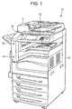
- Fig. 1 is a perspective view of an image forming apparatus 10 of a first exemplary embodiment.
- the image forming apparatus 10 is a multi-function apparatus having a scanning function, a printing function, a copying function, and a facsimile function.
- the image forming apparatus 10 includes a scanner 11, a printer 12, and a user interface (UI) 13.
- the scanner 11 reads an image formed on an original document.
- the printer 12 prints an image on a recording material.
- the user interface 13 receives an operation (instruction) from a user and displays a variety of information to the user when the user operates the image forming apparatus 10.
- the scanner 11 of the first exemplary embodiment is mounted on top of the printer 12.
- the user interface 13 is attached to the scanner 11.
- the user interface 13 is arranged on the front side of the image forming apparatus 10 (the scanner 11) in front of which the user stands to use the image forming apparatus 10.
- the user interface 13 faces upward such that the user standing in front of the front side of the image forming apparatus 10 looks downward on the user interface 13 from above while operating the user interface 13.
- the image forming apparatus 10 further includes a pyroelectric sensor 14, a first camera 15, and a second camera 16.
- the pyroelectric sensor 14 and the first camera 15 are disposed on the front-left side of the printer 12.
- the first camera 15 is disposed above the pyroelectric sensor 14.
- the second camera 16 as an example of an imaging unit is disposed on the left side of the user interface 13 and looks upward.
- the pyroelectric sensor 14 has a function of detecting the movement of a moving body including the user in front of the image forming apparatus 10.
- the first camera 15 is a video camera, and has a function of capturing an image of an area in front of the front side of the image forming apparatus 10.
- the second camera 16 is also a video camera and has a function of capturing the image of an area above the top side of the image forming apparatus 10.
- Each of the pyroelectric sensor 14, the first camera 15, and the second camera 16 functions as a departure detecting unit.
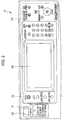
- Fig. 2 is a top view of the user interface 13 of Fig. 1 .
- Fig. 2 also illustrates the second camera 16 arranged on the user interface 13.
- the user interface 13 includes a touch panel 130, a first operation button group 131, a second operation button group 132, and a universal serial bus (USB) memory socket 133.
- the first operation button group 131 is disposed on the right side of the touch panel 130.
- the second operation button group 132, the USB memory socket 133, and the second camera 16 are disposed on the left side of the touch panel 130.
- the touch panel 130 as an example of a display displays information to the user using an image, and has a function of receiving an input from the user.
- the first operation button group 131 and the second operation button group 132 also have a function of receiving an input from the user.
- the USB memory socket 133 has a function of receiving a USB memory from the user.
- the second camera 16 disposed on the user interface 13 is arranged at a location where the image of the face of the user using the image forming apparatus 10 is captured.
- the image (including the image of the face of the user) captured by the second camera 16 is displayed on the touch panel 130.
- Fig. 3 is a block diagram illustrating the image forming apparatus 10.
- the image forming apparatus 10 includes a controller 101, a communication unit 102, an operation unit 103, a display 104, a memory 105, an image reading unit 106, an image forming unit 107, an image capturing and detecting unit 108, a face registration and authenticating unit 109, and a time measurement unit 110.
- the controller 101 functioning as a stopping unit, a controller, and a changing unit includes a central processing unit (CPU), and a memory, and controls the elements of the image forming apparatus 10.
- the CPU executes a program stored on a storage device or the memory 105.
- the memory may include a read-only memory (ROM) or a random-access memory (RAM).
- the ROM pre-stores a program or data.
- the RAM temporarily stores a program or data, and serves as a working area where the CPU executes the program.
- the communication unit 102 is a communication interface to be connected to a communication network (not illustrated).
- the communication unit 102 communicates with a client apparatus or another image forming apparatus (both apparatuses not illustrated) via the communication network.
- the operation unit 103 inputs to the controller 101 information responsive to an operation of the user.
- the operation unit 103 is implemented using the touch panel 130, the first operation button group 131 or the second operation button group 132 disposed on the user interface 13.
- the display 104 displays a variety of information to the user.
- the display 104 is implemented using the touch panel 130 disposed on the user interface 13.
- the memory 105 is a hard disk, for example, and stores a variety of programs and data to be used by the controller 101.
- the image reading unit 106 reads an image of an original document, and generates image data.
- the image reading unit 106 in this case is implemented by the scanner 11.
- the image forming unit 107 forms an image responsive to image data on a recording material sheet, such as a paper sheet.
- a recording material sheet such as a paper sheet.
- the image forming unit 107 is implemented by the printer 12.
- the image forming unit 107 may form image through an electrophotographic system or another system.
- the image capturing and detecting unit 108 captures or detects a imaging target.
- the image capturing and detecting unit 108 may be implemented by the pyroelectric sensor 14, the first camera 15 or the second camera 16.
- the face registration and authenticating unit 109 as an example of an authenticating unit or a face detecting unit registers the face image of a user in advance who is to be permitted to use the image forming apparatus 10.
- the face image of the user is captured and a feature quantity is extracted from the captured face image.
- the identification (ID) of the user, the face image of the user, and the feature quantity extracted from the face image of the user are stored in an associated state.
- the face registration and authenticating unit 109 authenticates the user using the face image.
- the face image of the user is captured, and the feature quantity is extracted from the captured face image.
- the image forming apparatus 10 determines whether the feature quantity obtained presently matches the registered feature quantity. If the two feature quantities match, the user is permitted to use the image forming apparatus 10. If there is no match in the feature quantities, the use of the image forming apparatus 10 is limited or entirely prohibited.
- the time measurement unit 110 is a timer, for example, and measures time in response to an instruction from the controller 101.
- the image forming apparatus 10 performs a scanning operation, a copying operation, a printing operation, a facsimile transmission operation, and a facsimile reception operation.
- the scanning operation reads an image from an original document, and generates image data.
- the scanning operation is performed by the image reading unit 106.
- the copying operation reads an image from an original document, generates image data, and forms an image on a recording material based on the image data.
- the copying operation is performed by the image reading unit 106 and the image forming unit 107.
- the printing operation forms an image on a recording material based on image data received from a client apparatus external to the image forming apparatus 10.
- the printing operation is performed by the communication unit 102 and the image forming unit 107.
- the facsimile transmission operation reads an image from an original document, generates image data, and transmits the generated image data to a facsimile apparatus via the communication unit 102.
- the facsimile transmission operation is performed by the image reading unit 106 and the communication unit 102.
- the facsimile reception operation forms an image on a recording material based image data received from a facsimile apparatus.
- the facsimile reception is performed by the communication unit 102 and the image forming unit 107.
- Fig. 10 illustrates an area where the image forming apparatus 10 detects the presence of a person.
- Fig. 10 is a plan view of the image forming apparatus 10 and an area surrounding the image forming apparatus 10 viewed from above in the height direction of the image forming apparatus 10.
- a sensing area F of the pyroelectric sensor 14 (see Fig. 1 ) is set up in front of the image forming apparatus 10, and has a generally sector shape if viewed from above in height.
- the person enters the sensing area F first.
- An approach sensing area R1 of Fig. 10 is formed in front of the image forming apparatus 10 and has a generally sector shape in a plan view if viewed from above in the direction of height.
- the approach sensing area R1 is set up to generally include the sensing area F.
- the person who approaches the image forming apparatus 10 enters the approach sensing area R1.
- a location labeled "P" in Fig. 10 where the first camera 15 is arranged is referred to as the location of the image forming apparatus 10.
- the approach sensing area R1 is a sector having a central angle of 180 degrees (semi-circle), but the central angle may be an angle other than 180 degrees.
- the first camera 15 is arranged so that the first camera 15 has at least the entire approach sensing area R1 as an imaging area.
- a presence sensing area R2 is set up in front of the image forming apparatus 10 and has a rectangular shape in a plan view if viewed from above in the direction of height.
- the rectangular area has a length W in the direction of width of the image forming apparatus 10 and a length D in the direction of depth of the image forming apparatus 10.
- the length W in the direction of width of the presence sensing area R2 is approximately equal to the length of the image forming apparatus 10 in the direction of width thereof.
- the presence sensing area R2 is closer to the image forming apparatus 10 than the approach sensing area R1. For this reason, the entire presence sensing area R2 is set up to be enclosed in the approach sensing area R1.
- the user of the image forming apparatus 10 enters the presence sensing area R2, and then stays within the presence sensing area R2 to perform an operation using the user interface 13.
- the controller 101 senses a person within each of the approach sensing area R1 and the presence sensing area R2 by analyzing the image captured by the first camera 15.
- the approach sensing area R1 and the presence sensing area R2 are not necessarily set up at a precision level exactly as illustrated Fig. 10 , and it is sufficient enough if the approach sensing area R1 and the presence sensing area R2 are set up at a precision level as high as the level estimated from the image captured by the first camera 15.
- Fig. 11 is a flowchart illustrating the process flow of controlling the mode of the image forming apparatus 10.
- the controller 101 monitors the sensing results of the quantity of infrared light with the pyroelectric sensor 14, and determines whether a person is present within the sensing area F. If a person enters the sensing area F, the controller 101 senses the presence of the person within the sensing area F in response to the sensing results of the pyroelectric sensor 14 (step S1).
- the controller 101 If the presence of the person is sensed within the sensing area F, the controller 101 starts supplying power to the first camera 15 and causes the first camera 15 to begin photographing the approach sensing area R1 (step S2). When the first camera 15 starts photographing, the controller 101 analyzes the image captured from the first camera 15, and then starts sensing the movement of the person by analyzing the image captured from the first camera 15 (step S3).
- the controller 101 estimates the distance from the image forming apparatus 10 to the person while calculating a motion vector indicating the movement of the person.
- the operation of sensing the movement of the person may be a related art technique.
- the controller 101 estimates the distance from the image forming apparatus 10 to the person based on the magnitude of a part of the body of the person detected from the captured image.
- the controller 101 also compares sequentially multiple frames of the captured images by performing a framing operation on the captured images from the first camera unit 15.
- the controller 101 senses the toe as the part of the body of the person, and calculates the motion vector by analyzing the movement of the sensed part.
- the controller 101 corrects the captured image from the first camera unit 15 (into a plan view form), and then senses the movement of the person.
- the controller 101 determines whether the approach of the person is detected within the approach sensing area R1 (step S4).
- the controller 101 may determine that the person is within the approach sensing area R1, and that the person moves toward the image forming apparatus 10.
- the controller 101 determines that the approach of the person has been sensed (yes branch from step S4).
- the controller 101 performs the operation to sense the movement of the person, and repeats the operation in step S4 to determine whether the person approaches (no branch from step S4).
- step S5 the controller 101 shifts the image forming apparatus 10 from the sleep mode to the standard mode (step S5).
- the controller 101 instructs the image forming apparatus 10 to supply power to each unit of the image forming apparatus 10 in response to the standard mode and starts up each unit of the image forming apparatus 10.
- the controller 101 starts supplying power to the second camera 16 and causes the second camera 16 to start photographing the presence sensing area R2.
- the controller 101 does not shift the image forming apparatus 10 to the standard mode immediately when the presence of a person has been sensed within the approach sensing area R1 but shifts the image forming apparatus 10 to the standard mode when the approach of the person to the image forming apparatus 10 has been sensed. This reduces the possibility that the image forming apparatus 10 is shifted to the standard mode when the person simply passes through the approach sensing area R1.
- the controller 101 starts an operation to sense the presence (staying) of the person within the presence sensing area R2 (step S6).
- the controller 101 senses a part of the body of the person by analyzing the captured image from the first camera unit 15, and senses the presence of the person within the presence sensing area R2 in accordance with the location and the size of the sensed part. For example, the controller 101 estimates the distance from the image forming apparatus 10 to the person in response to the size of the detected part of the body, and identifies a direction to the location of the person based on the location of the sensed part of the body.
- the controller 101 determines whether the person is present within the presence sensing area R2 (step S7). If the controller 101 determines that the person is present within the presence sensing area R2 (yes from step S7), processing returns to step S6. The controller 101 repeats the operation to sense the presence of the person within the presence sensing area R2 with the image forming apparatus 10 set in the standard mode until the presence of the person is no longer sensed within the presence sensing area R2.
- the person may move out of the presence sensing area R2 possibly because of the completion of the job with the image forming apparatus 10.
- the controller 101 determines that the person is no longer present within the presence sensing area R2 (no branch from step S7).
- the controller 101 causes the time measurement unit 110 to start measuring time (step S8). In other words, using the time measurement unit 110, the controller 101 measures elapsed time from when the person is no longer present within the presence sensing area R2.
- the controller 101 determines whether a person is present within the presence sensing area R2 (step S9). Once the person has been no longer present within the presence sensing area R2, the controller 101 determines in the operation of step S9 whether the presence of the person is detected again. For example, the person may gradually go away from the image forming apparatus 10 and no person may be present within the presence sensing area R2. The controller 101 then determines that the answer to the operation in step S9 is "no", and proceeds to step S10.
- the controller 101 determines whether the time set in the time measurement unit 110 has elapsed (step S10).
- the set time may be 1 minute, for example. Time different from 1 minute may also be set. If the controller 101 determines that the set time has not elapsed (no branch from step S10), processing returns to step S9. More specifically, the controller 101 determines in each of the steps S9 and S10 whether the period throughout which no person is present within the presence sensing area R2 is equal to the set time.
- step S10 the controller 101 shifts the image forming apparatus 10 from the standard mode to the sleep mode (step S11).
- the controller 101 instructs the image forming apparatus 10 to supply power for the sleep mode to each unit of the image forming apparatus 10 and suspends the operation of each unit in the image forming apparatus 10 that is to be suspended during the sleep mode.
- the controller 101 suspends the operation of the first camera unit 15.
- the controller 101 may sense the presence of a person again before the elapse of the set time from when the person is no longer present within the presence sensing area R2 after the start of the time measurement of the time measurement unit 110. In such a case, the controller 101 determines that the determination in step S9 is affirmative (yes), and processing proceeds to step S12. The controller 101 stops the time measurement of the time measurement unit 110 and resets the time measurement unit 110 (step S12). The controller 101 stops shifting to the sleep mode initiated by the no-presence of the person within the presence sensing area R2, and then returns to step S6. In other words, the controller 101 again executes the operation that applies to the case when the person is present within the presence sensing area R2.
- step S9 the controller 101 also determines that the determination in step S9 is affirmative (yes).
- a face authentication process to be performed by a user who is going to use the image forming apparatus 10 is described below.
- Fig. 4 is a flowchart illustrating the face authentication process of the first exemplary embodiment.
- the face authentication process is performed by the controller 101 and the face registration and authenticating unit 109 in the image forming apparatus 10.
- the pyroelectric sensor 14 may detect a person (user) in step S1 (see Fig. 11 ), the first camera 15 may be started in step S2, and the image forming apparatus 10 may shift from the sleep mode to the standard mode in step S5.
- the face authentication process starts in response to the detection of the presence of the person in step S6, followed by starting a face detection and matching process on the basis of the image captured by the second camera 16 (step S102).
- the image captured by the second camera 16 (hereinafter referred to as a camera image) is displayed on the touch panel 130 in the user interface 13. If the face of the user is present within the sensing area of the second camera 16, the camera image includes the face of the user.
- the image forming apparatus 10 determines whether the face of the user has been detected (step S104). In response to a non-affirmative determination in step S104 (no branch from step S104), processing proceeds to step S116. In response to an affirmative determination in step S104 (yes branch from step S104), the image forming apparatus 10 checks the feature quantity of the detected face against the feature quantity of the registered face to determine whether there is a match (as to whether face matching is successful or not) (step S106). In response to an affirmative determination (yes) in step S106, the image forming apparatus 10 authenticates the user as a matched user (step S108), and completes the face detection and matching process (step S110). The image forming apparatus 10 thus ends the face authentication process.
- step S106 determines whether an error timer using the time measurement unit 110 is untriggered (step S 112). In response to an affirmative determination (yes) in step S 112, the image forming apparatus 10 starts the error timer with a set period of time (first set time T1) (step S 114), and proceeds to step S116. On the other hand, in response to a non-affirmative determination (no) in step S 112, processing proceeds to step S116.
- the image forming apparatus 10 determines whether the set period of time of the started timer (first set time T1) has elapsed (step S116). In response to a non-affirmative determination (no) in step S116, processing returns to step S 104 to repeat the process. In response to an affirmative determination (yes) in step S116, the image forming apparatus 10 causes the touch panel 130 to display an error indication (step S118).
- the image forming apparatus 10 determines whether the user has pressed a close button with the error indication displayed (step S120). In response to a non-affirmative determination (no) in step S120, the image forming apparatus 10 determines whether a departure of the user from the area in front of the image forming apparatus 10 has been detected (step S122). The detection of the departure of the user in step S122 may be carried out in response to detection results by the pyroelectric sensor 14, imaging results by the first camera 15, and imaging results by the second camera 16. In response to a non-affrmative determination (no) in step S122, processing returns to step S120 to continue the process.
- step S120 in response to an affirmative determination (yes) in step S120, or in response to an affirmative determination (yes) in step S122, the image forming apparatus 10 causes the touch panel 130 to stop displaying the error indication (step S124). Processing returns to step S 104 to continue the process.
- Fig. 5 illustrates an example of display screens in the face authentication process of the first exemplary embodiment.
- a user who has registered his or her face (face registered) requests the face authentication with a mask worn.
- the first display screen from the top of Fig. 5 is displayed on the touch panel 130 in step S102.
- the first display screen displays a message to the user on the upper portion thereof, and a camera image captured by the second camera 16 on the lower portion thereof.
- the message here reads "face directly forward and look at center of screen".
- the camera image indicates the face of the user with the mask worn. Since the face is not detected from the camera image (because of the worn mask), the determination in step S104 is non-affirmative (no).
- the second display screen from the top of Fig. 5 is an error screen (error indication) displayed on the touch panel 130 in step S118 if the first set time T1 preset by the error timer in step S 114 has elapsed, and the determination in step S116 is affirmative (yes).
- the screen displays an error message to the user on the upper portion thereof, and a "close button” on the left-hand side of the lower portion thereof and a "authenticate button” on the right-hand side of the lower portion thereof.
- the error messages herein reads "authentication failed. Take off mask or glasses if worn. Press authenticate button for authentication with ID and password.” If the close button is pressed by the user, the determination in step S120 is affirmative (yes).
- the third display screen from the top of Fig. 5 is a screen displayed on the touch panel 130 in step S124 (subsequent to the end of the displaying of the error indication) after an affirmative determination (yes) in step S120.
- the screen displays the same message to the user as the message displayed on the first screen of Fig. 5 on the upper portion thereof and a camera image captured by the second camera 16 on the lower portion thereof.
- the user presses the close button on the second screen of Fig. 5 with the mask removed, and the camera face is the face of the user with the mask removed.
- step S104 An affirmative determination (yes) in step S104 in this case is followed by an affirmative determination (yes) in step S106.
- the user is thus successfully authenticated, and is permitted to use the image forming apparatus 10.
- Fig. 6 illustrates an example of the display screens in the face authentication process of the first exemplary embodiment.
- a user who has not registered his or her face (face unregistered) requests the face authentication process to be performed with no mask worn.
- the first display screen from the top of Fig. 6 is a screen displayed on the touch panel 130 in step S102.
- the first display screen of Fig. 6 is identical to the first display screen of Fig. 5 , and displays a message on the upper portion thereof and a camera image on the lower portion thereof.
- the camera image displays the face of the user having no mask worn.
- the face is detected from the camera image, and an affirmative determination (yes) is performed in step S104. Since the face of the user is not registered in this case, a non-affirmative determination (no) is performed in step S106.
- the second display screen from the top of Fig. 6 is an error screen (error indication) displayed on the touch panel 130 in step S118 if the first set time T1 preset in the error timer started in step S 114 has elapsed and the determination in step S116 is affirmative (yes).
- the error message in the second display screen of Fig. 6 is an example of failure information.
- the second display screen of Fig. 6 is identical to the second display screen of Fig. 5 except the face of the camera image, and the detailed discussion thereof is thus omitted herein.
- the third display screen from the top of Fig. 6 is a screen displayed on the touch panel 130 in step S124 (displayed subsequent to the end of the displaying of the error indication) in response to the affirmative determination (yes) in step S122 subsequent to the non-affirmative determination (no) in step S120.
- the screen displays the same message to the user as the first display screen of Fig. 6 on the upper portion thereof, and a camera image captured by the second camera 16 on the lower portion thereof. Since the determination in step S122 is affirmative (yes), in other words, no user is present in front of the image forming apparatus 10, the camera image indicates no face.
- the touch panel 130 is caused to stop displaying the error message if the departure of the user is detected with the error message displayed on the touch panel 130 to the user. In this way, an error message intended for a previous user is not displayed to a next user who may approach the image forming apparatus 10 in succession to the previous user. As a result, erroneous inputting by the next user is controlled.
- the departure of the user from the area in front of the image forming apparatus 10 is detected based on the detection results of the pyroelectric sensor 14, the imaging results of the first camera 15, and the imaging results of the second camera 16. Since the pyroelectric sensor 14 and the first camera 15 are arranged on the front side of the image forming apparatus 10, the detection results of the pyroelectric sensor 14 and the imaging results of the first camera 15 allow the departure of the user to be easily detected. If the imaging results of the second camera 16 are used, the camera image displayed on the touch panel 130 is shared as an image from which the departure of the user is detected.
- the structure of the image forming apparatus 10 may be simplified.
- the displaying of the error message is stopped when the departure of the user from the image forming apparatus 10 is detected.
- the present invention is not limited to this configuration.
- the controller 101 may start a power saving control operation in addition to the stopping of the displaying of the error message.
- the power saving control operation may include causing the touch panel 130 to stop backlighting, and shifting to a power saving mode in which power supplying to some elements of the image forming apparatus 10 is stopped.
- a second exemplary embodiment is partially different in the face authentication process from the first exemplary embodiment.
- elements identical to those in the first exemplary embodiment are designated with the same reference numerals, and the detailed discussion thereof is omitted herein.
- Fig. 7 is a flowchart illustrating the face authentication process of the second exemplary embodiment.
- the face authentication process is also carried out by the controller 101 and the authenticating unit 109 in the image forming apparatus 10.
- the pyroelectric sensor 14 may detect a person (user) in step S1 (see Fig. 11 ), the first camera 15 may be started in step S2, and the image forming apparatus 10 may shift from the sleep mode to the standard mode in step S5.
- the face authentication process starts in response to the detection of the presence of a person in step S6.
- the set period of time T is set to be the first set time T1 (step S202).
- a face detection and matching process starts in response to the image captured by the second camera 16 (step S204).
- step S204 the image captured by the second camera 16 is displayed on the touch panel 130 in the user interface 13. If the face of the user is present within the imaging area of the second camera 16, the camera image includes the face of the user.
- the image forming apparatus 10 determines whether the face of the user has been detected (step S206). In response to a non-affirmative determination in step S206 (no branch from step S206), processing proceeds to step S218. In response to an affirmative determination in step S206 (yes branch from step S206), the image forming apparatus 10 checks the feature quantity of the detected face against the feature quantity of the registered face to determine whether there is a match (as to whether face matching is successful or not) (step S208). In response to an affirmative determination (yes) in step S208, the image forming apparatus 10 authenticates the user as a matched user (step S210), and completes the face detection and matching process (step S212). The image forming apparatus 10 thus ends the face authentication process.
- step S208 determines whether an error timer using the time measurement unit 110 is untriggered (step S214). In response to an affirmative determination (yes) in step S214, the image forming apparatus 10 starts the error timer with the time setting T (step S216), and proceeds to step S218. On the other hand, in response to a non-affirmative determination (no) in step S214, processing proceeds to step S218.
- the image forming apparatus 10 determines whether the set period T of time of the started timer has elapsed (step S218). In response to a non-affirmative determination (no) in step S218, processing returns to step S206 to repeat the process. In response to an affirmative determination (yes) in step S218, the image forming apparatus 10 determines whether the set time T is set to be the first set time T1 (step S220).
- step S220 determines whether the departure of the user from the area in front of the image forming apparatus 10 has been detected (step S226).
- the departure of the user from the image forming apparatus 10 is detected in step S226 based on the detection results of the pyroelectric sensor 14, the imaging results of the first camera 15, or the imaging results of the second camera 16. If the determination in step S226 is non-affirmative (no), processing returns to step S206 to repeat the process.
- step S226 If the determination in step S226 is affirmative (yes), the time setting T is set to be the first time T1 (step S228).
- the image forming apparatus 10 causes the touch panel 130 to end the displaying of the confirmation screen (step S230). Processing returns to step S206 to repeat the process.
- step S220 determines whether the authenticate button has been pressed by the user (step S234). If the determination in step S234 is affirmative (yes), the image forming apparatus 10 shifts to keyboard authentication in which authentication is performed using an ID or password manually input by the user.
- the keyboard authentication is another authentication example different from the face authentication.
- step S234 determines the departure of the user from the area in front of the image forming apparatus 10 is detected with the error screen displayed (step S236). If the determination in step S236 is non-affirmative (no), processing returns to step S234 to continue the process. If the determination in step S236 is affirmative (yes), the time setting T is set to be the first set time T1. The image forming apparatus 10 causes the touch panel 130 to quit displaying the error screen (step S240). Processing returns to step S206 to repeat the process.
- Fig. 8 illustrates an example of display screens in the face authentication process of the second exemplary embodiment.
- a user who has completed face registration requests the face authentication to be performed with a mask worn.
- the first display screen from the top of Fig. 8 is a screen displayed on the touch panel 130 in step S204.
- the screen displays a message to the user on the upper portion thereof and a camera image captured by the second camera 16 on the lower portion thereof.
- the message herein reads "face directly forward and look at center of screen".
- the camera image displayed herein includes the face of the user with a mask worn. Since the face is not detected from the camera image (because of the worn mask), the determination in step S206 is non-affirmative (no).
- the second display screen from the top of Fig. 8 is a confirmation screen displayed on the touch panel 130 in step S222 if the first set time T1 set in step S202 on the error timer started in step S216 elapses, and the determination in step S218 is affirmative (yes), followed by an affirmative determination (yes) in step S220.
- the screen displays an error message to the user on the upper portion thereof and a camera screen on the lower portion thereof.
- the error message herein reads "Authentication failed. Take off mask or glasses if worn”.
- the time setting T is changed from the first set time T1 to the second set time T2 (T2 > T1) in step S224.
- the first set time T1 is set to be about 5 seconds
- the second set time T2 is set to be about 20 seconds.
- the third display screen from the top of Fig. 8 is a screen displayed on the touch panel 130 subsequent to the non-affirmative determination (no) in step S226.
- the screen displays the same error message to the user as the second display screen of Fig. 8 on the upper portion thereof and a camera image captured by the second camera 16 on the lower portion thereof. Since the user has taken his or her mask off on the confirmation screen in the second display screen of Fig. 8 , the camera image includes the face of the user.
- step S206 The determination in step S206 is affirmative (yes), followed by the affirmative determination (yes) in step S208.
- the user is thus successfully authenticated and permitted to use the image forming apparatus 10.
- Fig. 9 illustrates another example of the display screens of the face authentication process of the second exemplary embodiment.
- a user who has not registered his or her face (face unregistered) requests the face authentication with no mask worn.
- the first display screen from the top of Fig. 9 is a screen displayed on the touch panel 130 in step S204.
- the first display screen of Fig. 9 is identical to the first display screen of Fig. 8 .
- the screen displays a message on the upper portion thereof and a camera image on the lower portion thereof.
- the camera image includes the face of the user with no mask worn. The face is thus detected from the camera image, and the determination in step S206 is affirmative (yes). Since the face of the user is not registered on the other hand, the determination in step S208 is non-affirmative (no).
- the second screen from the top of Fig. 9 is a confirmation screen displayed on the touch panel 130 in step S222 if the first set time T1 set in step S202 on the error timer started in step S216 elapses, and the determination in step S218 is affirmative (yes), followed by the affirmative determination in step S220.
- An error message in the second screen of Fig. 9 is an example of the failure information.
- the second screen of Fig. 9 is similar to the second screen of Fig. 8 , and the detailed discussion thereof is omitted herein.
- the time setting T is changed from the first set time T1 to the second set time T2 (T2 > T1) in step S224.
- the third screen from the top of Fig. 9 is an error screen displayed on the touch panel 130 in step S232 if the determination in step S220 is non-affirmative (no) with the time setting T set to the second set time T2 in step S224.
- the error message in the third screen of Fig. 9 is another example of the failure information.
- the screen displays a message to the user on the upper portion thereof, a "close button” on the lower left portion thereof, and a "register button” on the lower right portion thereof.
- the message herein reads "Authentication failed. Press authenticate button for authentication with ID and password or press register button for registration". If the authenticate button is pressed by the user, the determination in step S234 is affirmative (yes).
- the fourth screen from the top of Fig. 9 is a screen (subsequent to the end of the error indication) displayed on the touch panel 130 in step S240 if the determination in step S234 is non-affirmative (no), followed by the affirmative determination (yes) in step S236.
- the screen displays the same message to the user as the first screen of Fig. 9 on the upper portion thereof, and a camera image captured by the second camera 16. Note that the determination in step S236 is affirmative (yes). Since no user is present in front of the image forming apparatus 10, no user's face is included in the camera image.
- the face authentication process continues if the "confirmation screen" is displayed in step S222. In contrast, the face authentication process is suspended if the "error screen” is displayed in step S232.
- the image forming apparatus 10 causes the touch panel 130 to stop displaying the error message if the departure of the user is detected with the error message displayed on the touch panel 130. In this way, an error message intended for a previous user is not displayed to a next user who may approach the image forming apparatus 10 in succession to the previous user. As a result, erroneous inputting by the next user is controlled.
- a first error message (confirmation screen) including information related to the face authentication is displayed to the user, and then, a second error message (error screen) including information related to authentication other than the face authentication is displayed to the user.
- the user is thus allowed to be authenticated in a different authentication method.
- the first error message (confirmation screen) is displayed after the time elapse of the first set time T1
- the second error message (error screen) is displayed after the time elapse of the second set time T2 longer than the first set time. Since the first error message is displayed with the first set time T1 elapsed, the user has time to adjust how the user's face is captured, before the suspension of the face authentication. The second set time T2 longer than the first set time T1 makes it more difficult for the authentication method to simply return back to the face authentication method. Note that the user may desire to be authenticated in an authentication method other than the face authentication method or may desire to register the face image.
- the authentication is performed by checking the face image of the user captured by the second camera 16 against the face image of the registered user. As long as the face image captured from the user is used, a variety of authentication techniques may be used.
Landscapes
- Engineering & Computer Science (AREA)
- Signal Processing (AREA)
- Multimedia (AREA)
- Artificial Intelligence (AREA)
- Computer Vision & Pattern Recognition (AREA)
- Human Computer Interaction (AREA)
- Computing Systems (AREA)
- Health & Medical Sciences (AREA)
- Computer Hardware Design (AREA)
- Computer Security & Cryptography (AREA)
- Biomedical Technology (AREA)
- General Engineering & Computer Science (AREA)
- Computer Networks & Wireless Communication (AREA)
- General Health & Medical Sciences (AREA)
- Control Or Security For Electrophotography (AREA)
- Accessory Devices And Overall Control Thereof (AREA)
- Collating Specific Patterns (AREA)
- Image Processing (AREA)
- Facsimiles In General (AREA)
- Image Analysis (AREA)
Abstract
Description
- The present invention relates to an authentication apparatus, an image forming apparatus, an authentication method, and an image forming method.
- As described in the related art, there is a technique that a CCD camera is provided on an operation panel of a copying machine, a user's face is imaged by the CCD camera, it is determined whether or not a user is a valid user or not by comparing a feature amount of the face image obtained by imaging with the feature amount registered in advance, and in a case where the user is the valid user, the use of the copying machine is permitted (authorized), and in a case where the user is not the valid user, the use of the copying machine is not permitted (
JP-A-2002-111924 - As described in another related art, there is a technique that when a feature amount of a user's face image obtained by imaging does not matched with a feature amount registered in advance, an input of personal identification information is requested to the user (
JP-A-2009-64140 JP-A-2009-64140 - Here, it is considered that, in a case where an unregistered user who is not permitted to use a device tries to perform authentication (face authentication) based on imaging of a face image, the matching result is a mismatch, and a screen indicating failure of the authentication is displayed to the unregistered user. However, in such a case, in a case where the unregistered user (previous user) leaves from the device, a screen indicating failure of the authentication to be presented to the previous user is displayed to a next user who approaches the device following the previous user. In such a case, the next user is required to perform operation that is essentially unnecessary, such as an operation for converting the display screen from the screen indicating failure of the authentication to the screen for authentication.
- An object of the invention is to prevent information to be presented to the previous user from continuing to be displayed, even after the previous user has already left.
- A first aspect of the invention is directed to an authentication apparatus comprising: an imaging unit that captures a face image of a user; an authenticating unit that authenticates the user using the face image of the user captured by the imaging unit; a display unit that displays failure information if authentication of the user by the authenticating unit is unsuccessful; a departure detecting unit that detects a departure of the user; and a stopping unit that causes the display unit to stop displaying the failure information if the departure detecting unit detects the departure of the user.
- A second aspect of the invention is directed to the authentication apparatus according to the first aspect of the invention, wherein the departure detecting unit comprises an infrared sensor that detects an infrared ray or a camera that captures an image.
- A third aspect of the invention is directed to the authentication apparatus according to the first aspect of the invention, wherein the imaging unit also serves as the departure detecting unit.
- A fourth aspect of the invention is directed to the authentication apparatus according to any one of the first to third aspects of the invention, further comprising a controller that controls power consumption to a lower value if the departure detecting unit detects the departure of the user.
- A fifth aspect of the invention is directed to the authentication apparatus according to any one of the first to fourth aspects of the invention, further comprising: a face detecting unit that detects the face image of the user from the image captured by the imaging unit; and a time measurement unit that measures a time period elapsed from the detection of the face image of the user by the face detecting unit, wherein the display unit displays the failure information if the authentication of the user by the authenticating unit is uncompleted with the elapsed time period having exceeded a first time period.
- A sixth aspect of the invention is directed to the authentication apparatus according to the fifth aspect of the invention, further comprising a changing unit that changes the first time period to a second time period longer than the first time period after the elapsed time exceeded the first time period, wherein the display unit displays second failure information different from the failure information if the elapsed time measured by the time measurement unit exceeds the second time period.
- A seventh aspect of the invention is directed to the authentication apparatus according to the sixth aspect of the invention, wherein the failure information includes information related to authentication using the face image, and wherein the second failure information includes information related to second authentication different from the authentication using the face image.
- An eighth aspect of the invention is directed to the authentication apparatus according to the seventh aspect of the invention, wherein the second authentication is based on an input entered by a user.
- A ninth aspect of the invention is directed to the authentication apparatus according to the sixth aspect of the invention, wherein the changing unit changes the second time period to the first time period if the departure detecting unit detects the departure of the user with the second time period set.
- A tenth aspect of the invention is directed to an image forming apparatus, comprising: an image forming unit that forms an image on a recording material; an imaging unit that captures a face image of a user; an authenticating unit that authenticates the user using the face image of the user captured by the imaging unit in order to permit the user to use the image forming unit; a display unit that displays failure information if authentication by the authenticating unit is unsuccessful; a departure detecting unit that detects a departure of the user; and a stopping unit that causes the display unit to stop displaying the failure information if the departure detecting unit detects the departure of the user.
- An eleventh aspect of the invention is directed to an authentication method comprising: capturing a face image of a user; authenticating the user using the captured face image of the user; displaying failure information if authentication of the user is unsuccessful; detecting a departure of the user; and stopping displaying the failure information if the departure of the user is detected.
- A twelfth aspect of the invention is directed to an image forming method, comprising: forming an image on a recording material; capturing a face image of a user; authenticating the user using the captured face image of the user in order to permit the image to be formed; displaying failure information if the authenticating is unsuccessful; detecting a departure of the user; and stopping displaying the failure information if the departure of the user is detected.
- According to the first and eleventh aspects of the invention, it is possible to prevent information to be presented to the previous user from continuing to be displayed, even after the previous user has already left.
- According to the second aspect of the invention, it is possible to easily detect the departure of the user.
- According to the third aspect of the invention, it is possible to simplify the structure of the apparatus.
- According to the fourth aspect of the invention, it is possible to suppress wasteful power consumption.
- According to the fifth aspect of the invention, it is possible to allow a time to the user for adjusting an imaging condition of a face.
- According to the sixth aspect of the invention, it is possible to suppress continuous presentation of the same failure information.
- According to the seventh aspect of the invention, it is possible to present appropriate failure information to the user.
- According to the eighth aspect of the invention, even in a case where the face authentication fails, the user can perform appropriate authentication.
- According to the ninth aspect of the invention, even in a case where a new user appears, it is possible to appropriately instruct to the new user.
- According to the tenth and twelfth aspects of the invention, it is possible to prevent information to be presented to the previous user from continuing to be displayed, even after the previous user has already left.
- Exemplary embodiments of the present invention will be described in detail based on the following figures, wherein:
-
Fig. 1 is a perspective view of an image forming apparatus; -
Fig. 2 is a top view of a user interface; -
Fig. 3 is a block diagram of the image forming apparatus; -
Fig. 4 is a flowchart illustrating a face authentication process of a first exemplary embodiment; -
Fig. 5 illustrates an example of display screens in the face authentication process of the first exemplary embodiment; -
Fig. 6 illustrates another example of the display screens in the face authentication process of the first exemplary embodiment; -
Fig. 7 is a flowchart illustrating the face authentication process of a second exemplary embodiment; -
Fig. 8 illustrates an example of display screens in the face authentication process of the second exemplary embodiment; -
Fig. 9 illustrates another example of the display screens of the face authentication process of the second exemplary embodiment; -
Fig. 10 illustrates an area where the image forming apparatus detects the presence of a person; and -
Fig. 11 is a flowchart illustrating a process control flow of a mode of the image forming apparatus. - Exemplary embodiments of the invention are described with reference to the drawings.
-
Fig. 1 is a perspective view of animage forming apparatus 10 of a first exemplary embodiment. Theimage forming apparatus 10 is a multi-function apparatus having a scanning function, a printing function, a copying function, and a facsimile function. - The
image forming apparatus 10 includes ascanner 11, aprinter 12, and a user interface (UI) 13. Thescanner 11 reads an image formed on an original document. Theprinter 12 prints an image on a recording material. Theuser interface 13 receives an operation (instruction) from a user and displays a variety of information to the user when the user operates theimage forming apparatus 10. - The
scanner 11 of the first exemplary embodiment is mounted on top of theprinter 12. Theuser interface 13 is attached to thescanner 11. Theuser interface 13 is arranged on the front side of the image forming apparatus 10 (the scanner 11) in front of which the user stands to use theimage forming apparatus 10. Theuser interface 13 faces upward such that the user standing in front of the front side of theimage forming apparatus 10 looks downward on theuser interface 13 from above while operating theuser interface 13. - The
image forming apparatus 10 further includes apyroelectric sensor 14, afirst camera 15, and asecond camera 16. Thepyroelectric sensor 14 and thefirst camera 15 are disposed on the front-left side of theprinter 12. Thefirst camera 15 is disposed above thepyroelectric sensor 14. Thesecond camera 16 as an example of an imaging unit is disposed on the left side of theuser interface 13 and looks upward. - The
pyroelectric sensor 14 has a function of detecting the movement of a moving body including the user in front of theimage forming apparatus 10. Thefirst camera 15 is a video camera, and has a function of capturing an image of an area in front of the front side of theimage forming apparatus 10. Thesecond camera 16 is also a video camera and has a function of capturing the image of an area above the top side of theimage forming apparatus 10. Each of thepyroelectric sensor 14, thefirst camera 15, and thesecond camera 16 functions as a departure detecting unit. -
Fig. 2 is a top view of theuser interface 13 ofFig. 1 .Fig. 2 also illustrates thesecond camera 16 arranged on theuser interface 13. - The
user interface 13 includes atouch panel 130, a firstoperation button group 131, a second operation button group 132, and a universal serial bus (USB)memory socket 133. The firstoperation button group 131 is disposed on the right side of thetouch panel 130. The second operation button group 132, theUSB memory socket 133, and thesecond camera 16 are disposed on the left side of thetouch panel 130. - The
touch panel 130 as an example of a display displays information to the user using an image, and has a function of receiving an input from the user. The firstoperation button group 131 and the second operation button group 132 also have a function of receiving an input from the user. TheUSB memory socket 133 has a function of receiving a USB memory from the user. - The
second camera 16 disposed on theuser interface 13 is arranged at a location where the image of the face of the user using theimage forming apparatus 10 is captured. The image (including the image of the face of the user) captured by thesecond camera 16 is displayed on thetouch panel 130. -
Fig. 3 is a block diagram illustrating theimage forming apparatus 10. Theimage forming apparatus 10 includes acontroller 101, acommunication unit 102, anoperation unit 103, adisplay 104, amemory 105, animage reading unit 106, animage forming unit 107, an image capturing and detectingunit 108, a face registration and authenticatingunit 109, and atime measurement unit 110. - The
controller 101 functioning as a stopping unit, a controller, and a changing unit includes a central processing unit (CPU), and a memory, and controls the elements of theimage forming apparatus 10. The CPU executes a program stored on a storage device or thememory 105. The memory may include a read-only memory (ROM) or a random-access memory (RAM). The ROM pre-stores a program or data. The RAM temporarily stores a program or data, and serves as a working area where the CPU executes the program. - The
communication unit 102 is a communication interface to be connected to a communication network (not illustrated). Thecommunication unit 102 communicates with a client apparatus or another image forming apparatus (both apparatuses not illustrated) via the communication network. - The
operation unit 103 inputs to thecontroller 101 information responsive to an operation of the user. In this case, theoperation unit 103 is implemented using thetouch panel 130, the firstoperation button group 131 or the second operation button group 132 disposed on theuser interface 13. - The
display 104 displays a variety of information to the user. Thedisplay 104 is implemented using thetouch panel 130 disposed on theuser interface 13. - The
memory 105 is a hard disk, for example, and stores a variety of programs and data to be used by thecontroller 101. - The
image reading unit 106 reads an image of an original document, and generates image data. Theimage reading unit 106 in this case is implemented by thescanner 11. - The
image forming unit 107 forms an image responsive to image data on a recording material sheet, such as a paper sheet. In this case, theimage forming unit 107 is implemented by theprinter 12. Theimage forming unit 107 may form image through an electrophotographic system or another system. - The image capturing and detecting
unit 108 captures or detects a imaging target. The image capturing and detectingunit 108 may be implemented by thepyroelectric sensor 14, thefirst camera 15 or thesecond camera 16. - The face registration and authenticating
unit 109 as an example of an authenticating unit or a face detecting unit registers the face image of a user in advance who is to be permitted to use theimage forming apparatus 10. In the registration, the face image of the user is captured and a feature quantity is extracted from the captured face image. The identification (ID) of the user, the face image of the user, and the feature quantity extracted from the face image of the user are stored in an associated state. When the user uses theimage forming apparatus 10, the face registration and authenticatingunit 109 authenticates the user using the face image. In the authentication, the face image of the user is captured, and the feature quantity is extracted from the captured face image. Theimage forming apparatus 10 determines whether the feature quantity obtained presently matches the registered feature quantity. If the two feature quantities match, the user is permitted to use theimage forming apparatus 10. If there is no match in the feature quantities, the use of theimage forming apparatus 10 is limited or entirely prohibited. - The
time measurement unit 110 is a timer, for example, and measures time in response to an instruction from thecontroller 101. - The
image forming apparatus 10 performs a scanning operation, a copying operation, a printing operation, a facsimile transmission operation, and a facsimile reception operation. The scanning operation reads an image from an original document, and generates image data. The scanning operation is performed by theimage reading unit 106. The copying operation reads an image from an original document, generates image data, and forms an image on a recording material based on the image data. The copying operation is performed by theimage reading unit 106 and theimage forming unit 107. The printing operation forms an image on a recording material based on image data received from a client apparatus external to theimage forming apparatus 10. The printing operation is performed by thecommunication unit 102 and theimage forming unit 107. The facsimile transmission operation reads an image from an original document, generates image data, and transmits the generated image data to a facsimile apparatus via thecommunication unit 102. The facsimile transmission operation is performed by theimage reading unit 106 and thecommunication unit 102. The facsimile reception operation forms an image on a recording material based image data received from a facsimile apparatus. The facsimile reception is performed by thecommunication unit 102 and theimage forming unit 107. -
Fig. 10 illustrates an area where theimage forming apparatus 10 detects the presence of a person.Fig. 10 is a plan view of theimage forming apparatus 10 and an area surrounding theimage forming apparatus 10 viewed from above in the height direction of theimage forming apparatus 10. - Referring to
Fig. 10 , a sensing area F of the pyroelectric sensor 14 (seeFig. 1 ) is set up in front of theimage forming apparatus 10, and has a generally sector shape if viewed from above in height. When a person intending to use theimage forming apparatus 10 approaches theimage forming apparatus 10, the person enters the sensing area F first. - An approach sensing area R1 of
Fig. 10 is formed in front of theimage forming apparatus 10 and has a generally sector shape in a plan view if viewed from above in the direction of height. The approach sensing area R1 is set up to generally include the sensing area F. The person who approaches theimage forming apparatus 10 enters the approach sensing area R1. A location labeled "P" inFig. 10 where thefirst camera 15 is arranged is referred to as the location of theimage forming apparatus 10. The approach sensing area R1 is a sector having a central angle of 180 degrees (semi-circle), but the central angle may be an angle other than 180 degrees. However, thefirst camera 15 is arranged so that thefirst camera 15 has at least the entire approach sensing area R1 as an imaging area. - A presence sensing area R2 is set up in front of the
image forming apparatus 10 and has a rectangular shape in a plan view if viewed from above in the direction of height. The rectangular area has a length W in the direction of width of theimage forming apparatus 10 and a length D in the direction of depth of theimage forming apparatus 10. The length W in the direction of width of the presence sensing area R2 is approximately equal to the length of theimage forming apparatus 10 in the direction of width thereof. The presence sensing area R2 is closer to theimage forming apparatus 10 than the approach sensing area R1. For this reason, the entire presence sensing area R2 is set up to be enclosed in the approach sensing area R1. The user of theimage forming apparatus 10 enters the presence sensing area R2, and then stays within the presence sensing area R2 to perform an operation using theuser interface 13. - The
controller 101 senses a person within each of the approach sensing area R1 and the presence sensing area R2 by analyzing the image captured by thefirst camera 15. The approach sensing area R1 and the presence sensing area R2 are not necessarily set up at a precision level exactly as illustratedFig. 10 , and it is sufficient enough if the approach sensing area R1 and the presence sensing area R2 are set up at a precision level as high as the level estimated from the image captured by thefirst camera 15. -
Fig. 11 is a flowchart illustrating the process flow of controlling the mode of theimage forming apparatus 10. - With the
image forming apparatus 10 operating in the sleep mode, thecontroller 101 monitors the sensing results of the quantity of infrared light with thepyroelectric sensor 14, and determines whether a person is present within the sensing area F. If a person enters the sensing area F, thecontroller 101 senses the presence of the person within the sensing area F in response to the sensing results of the pyroelectric sensor 14 (step S1). - If the presence of the person is sensed within the sensing area F, the
controller 101 starts supplying power to thefirst camera 15 and causes thefirst camera 15 to begin photographing the approach sensing area R1 (step S2). When thefirst camera 15 starts photographing, thecontroller 101 analyzes the image captured from thefirst camera 15, and then starts sensing the movement of the person by analyzing the image captured from the first camera 15 (step S3). - In the operation of sensing the movement of the person in step S3, the
controller 101 estimates the distance from theimage forming apparatus 10 to the person while calculating a motion vector indicating the movement of the person. The operation of sensing the movement of the person may be a related art technique. For example, thecontroller 101 estimates the distance from theimage forming apparatus 10 to the person based on the magnitude of a part of the body of the person detected from the captured image. Thecontroller 101 also compares sequentially multiple frames of the captured images by performing a framing operation on the captured images from thefirst camera unit 15. In this case, thecontroller 101 senses the toe as the part of the body of the person, and calculates the motion vector by analyzing the movement of the sensed part. For example, thecontroller 101 corrects the captured image from the first camera unit 15 (into a plan view form), and then senses the movement of the person. - The
controller 101 determines whether the approach of the person is detected within the approach sensing area R1 (step S4). Thecontroller 101 may determine that the person is within the approach sensing area R1, and that the person moves toward theimage forming apparatus 10. Thecontroller 101 then determines that the approach of the person has been sensed (yes branch from step S4). - Note that during the period throughout which the
pyroelectric sensor 14 senses the presence of the person, thecontroller 101 performs the operation to sense the movement of the person, and repeats the operation in step S4 to determine whether the person approaches (no branch from step S4). - In the yes branch from step S4, the
controller 101 shifts theimage forming apparatus 10 from the sleep mode to the standard mode (step S5). Thecontroller 101 instructs theimage forming apparatus 10 to supply power to each unit of theimage forming apparatus 10 in response to the standard mode and starts up each unit of theimage forming apparatus 10. Thecontroller 101 starts supplying power to thesecond camera 16 and causes thesecond camera 16 to start photographing the presence sensing area R2. - The
controller 101 does not shift theimage forming apparatus 10 to the standard mode immediately when the presence of a person has been sensed within the approach sensing area R1 but shifts theimage forming apparatus 10 to the standard mode when the approach of the person to theimage forming apparatus 10 has been sensed. This reduces the possibility that theimage forming apparatus 10 is shifted to the standard mode when the person simply passes through the approach sensing area R1. - The
controller 101 starts an operation to sense the presence (staying) of the person within the presence sensing area R2 (step S6). Thecontroller 101 senses a part of the body of the person by analyzing the captured image from thefirst camera unit 15, and senses the presence of the person within the presence sensing area R2 in accordance with the location and the size of the sensed part. For example, thecontroller 101 estimates the distance from theimage forming apparatus 10 to the person in response to the size of the detected part of the body, and identifies a direction to the location of the person based on the location of the sensed part of the body. - The
controller 101 determines whether the person is present within the presence sensing area R2 (step S7). If thecontroller 101 determines that the person is present within the presence sensing area R2 (yes from step S7), processing returns to step S6. Thecontroller 101 repeats the operation to sense the presence of the person within the presence sensing area R2 with theimage forming apparatus 10 set in the standard mode until the presence of the person is no longer sensed within the presence sensing area R2. - The person may move out of the presence sensing area R2 possibly because of the completion of the job with the
image forming apparatus 10. In such a case, thecontroller 101 determines that the person is no longer present within the presence sensing area R2 (no branch from step S7). Thecontroller 101 causes thetime measurement unit 110 to start measuring time (step S8). In other words, using thetime measurement unit 110, thecontroller 101 measures elapsed time from when the person is no longer present within the presence sensing area R2. - The
controller 101 determines whether a person is present within the presence sensing area R2 (step S9). Once the person has been no longer present within the presence sensing area R2, thecontroller 101 determines in the operation of step S9 whether the presence of the person is detected again. For example, the person may gradually go away from theimage forming apparatus 10 and no person may be present within the presence sensing area R2. Thecontroller 101 then determines that the answer to the operation in step S9 is "no", and proceeds to step S10. - The
controller 101 determines whether the time set in thetime measurement unit 110 has elapsed (step S10). The set time may be 1 minute, for example. Time different from 1 minute may also be set. If thecontroller 101 determines that the set time has not elapsed (no branch from step S10), processing returns to step S9. More specifically, thecontroller 101 determines in each of the steps S9 and S10 whether the period throughout which no person is present within the presence sensing area R2 is equal to the set time. - In response to the affirmative determination (yes branch from step S10), the
controller 101 shifts theimage forming apparatus 10 from the standard mode to the sleep mode (step S11). In this operation, thecontroller 101 instructs theimage forming apparatus 10 to supply power for the sleep mode to each unit of theimage forming apparatus 10 and suspends the operation of each unit in theimage forming apparatus 10 that is to be suspended during the sleep mode. When the presence of the person is no longer sensed within the sensing area F, thecontroller 101 suspends the operation of thefirst camera unit 15. - The
controller 101 may sense the presence of a person again before the elapse of the set time from when the person is no longer present within the presence sensing area R2 after the start of the time measurement of thetime measurement unit 110. In such a case, thecontroller 101 determines that the determination in step S9 is affirmative (yes), and processing proceeds to step S12. Thecontroller 101 stops the time measurement of thetime measurement unit 110 and resets the time measurement unit 110 (step S12). Thecontroller 101 stops shifting to the sleep mode initiated by the no-presence of the person within the presence sensing area R2, and then returns to step S6. In other words, thecontroller 101 again executes the operation that applies to the case when the person is present within the presence sensing area R2. - It is assumed herein that the same person has returned back. If a different person comes into the presence sensing area R2, the
controller 101 also determines that the determination in step S9 is affirmative (yes). - A face authentication process to be performed by a user who is going to use the
image forming apparatus 10 is described below. -
Fig. 4 is a flowchart illustrating the face authentication process of the first exemplary embodiment. The face authentication process is performed by thecontroller 101 and the face registration and authenticatingunit 109 in theimage forming apparatus 10. - The
pyroelectric sensor 14 may detect a person (user) in step S1 (seeFig. 11 ), thefirst camera 15 may be started in step S2, and theimage forming apparatus 10 may shift from the sleep mode to the standard mode in step S5. The face authentication process starts in response to the detection of the presence of the person in step S6, followed by starting a face detection and matching process on the basis of the image captured by the second camera 16 (step S102). In step S102, the image captured by the second camera 16 (hereinafter referred to as a camera image) is displayed on thetouch panel 130 in theuser interface 13. If the face of the user is present within the sensing area of thesecond camera 16, the camera image includes the face of the user. - The
image forming apparatus 10 determines whether the face of the user has been detected (step S104). In response to a non-affirmative determination in step S104 (no branch from step S104), processing proceeds to step S116. In response to an affirmative determination in step S104 (yes branch from step S104), theimage forming apparatus 10 checks the feature quantity of the detected face against the feature quantity of the registered face to determine whether there is a match (as to whether face matching is successful or not) (step S106). In response to an affirmative determination (yes) in step S106, theimage forming apparatus 10 authenticates the user as a matched user (step S108), and completes the face detection and matching process (step S110). Theimage forming apparatus 10 thus ends the face authentication process. - In response to a non-affirmative determination (no) in step S106, the
image forming apparatus 10 determines whether an error timer using thetime measurement unit 110 is untriggered (step S 112). In response to an affirmative determination (yes) in step S 112, theimage forming apparatus 10 starts the error timer with a set period of time (first set time T1) (step S 114), and proceeds to step S116. On the other hand, in response to a non-affirmative determination (no) in step S 112, processing proceeds to step S116. - The
image forming apparatus 10 determines whether the set period of time of the started timer (first set time T1) has elapsed (step S116). In response to a non-affirmative determination (no) in step S116, processing returns to stepS 104 to repeat the process. In response to an affirmative determination (yes) in step S116, theimage forming apparatus 10 causes thetouch panel 130 to display an error indication (step S118). - The
image forming apparatus 10 determines whether the user has pressed a close button with the error indication displayed (step S120). In response to a non-affirmative determination (no) in step S120, theimage forming apparatus 10 determines whether a departure of the user from the area in front of theimage forming apparatus 10 has been detected (step S122). The detection of the departure of the user in step S122 may be carried out in response to detection results by thepyroelectric sensor 14, imaging results by thefirst camera 15, and imaging results by thesecond camera 16. In response to a non-affrmative determination (no) in step S122, processing returns to step S120 to continue the process. - On the other hand, in response to an affirmative determination (yes) in step S120, or in response to an affirmative determination (yes) in step S122, the
image forming apparatus 10 causes thetouch panel 130 to stop displaying the error indication (step S124). Processing returns to stepS 104 to continue the process. - A variety of display screens presented on the
touch panel 130 in the face authentication process of the first exemplary embodiment are described below. -
Fig. 5 illustrates an example of display screens in the face authentication process of the first exemplary embodiment. Referring toFig. 5 , a user who has registered his or her face (face registered) requests the face authentication with a mask worn. - The first display screen from the top of
Fig. 5 is displayed on thetouch panel 130 in step S102. The first display screen displays a message to the user on the upper portion thereof, and a camera image captured by thesecond camera 16 on the lower portion thereof. The message here reads "face directly forward and look at center of screen". The camera image indicates the face of the user with the mask worn. Since the face is not detected from the camera image (because of the worn mask), the determination in step S104 is non-affirmative (no). - The second display screen from the top of
Fig. 5 is an error screen (error indication) displayed on thetouch panel 130 in step S118 if the first set time T1 preset by the error timer instep S 114 has elapsed, and the determination in step S116 is affirmative (yes). The screen displays an error message to the user on the upper portion thereof, and a "close button" on the left-hand side of the lower portion thereof and a "authenticate button" on the right-hand side of the lower portion thereof. The error messages herein reads "authentication failed. Take off mask or glasses if worn. Press authenticate button for authentication with ID and password." If the close button is pressed by the user, the determination in step S120 is affirmative (yes). - The third display screen from the top of
Fig. 5 is a screen displayed on thetouch panel 130 in step S124 (subsequent to the end of the displaying of the error indication) after an affirmative determination (yes) in step S120. The screen displays the same message to the user as the message displayed on the first screen ofFig. 5 on the upper portion thereof and a camera image captured by thesecond camera 16 on the lower portion thereof. However, the user presses the close button on the second screen ofFig. 5 with the mask removed, and the camera face is the face of the user with the mask removed. - An affirmative determination (yes) in step S104 in this case is followed by an affirmative determination (yes) in step S106. The user is thus successfully authenticated, and is permitted to use the
image forming apparatus 10. -
Fig. 6 illustrates an example of the display screens in the face authentication process of the first exemplary embodiment. Referring toFig. 6 , a user who has not registered his or her face (face unregistered) requests the face authentication process to be performed with no mask worn. - The first display screen from the top of
Fig. 6 is a screen displayed on thetouch panel 130 in step S102. The first display screen ofFig. 6 is identical to the first display screen ofFig. 5 , and displays a message on the upper portion thereof and a camera image on the lower portion thereof. However, note that the camera image displays the face of the user having no mask worn. In this example, the face is detected from the camera image, and an affirmative determination (yes) is performed in step S104. Since the face of the user is not registered in this case, a non-affirmative determination (no) is performed in step S106. - The second display screen from the top of
Fig. 6 is an error screen (error indication) displayed on thetouch panel 130 in step S118 if the first set time T1 preset in the error timer started instep S 114 has elapsed and the determination in step S116 is affirmative (yes). The error message in the second display screen ofFig. 6 is an example of failure information. The second display screen ofFig. 6 is identical to the second display screen ofFig. 5 except the face of the camera image, and the detailed discussion thereof is thus omitted herein. - The third display screen from the top of
Fig. 6 is a screen displayed on thetouch panel 130 in step S124 (displayed subsequent to the end of the displaying of the error indication) in response to the affirmative determination (yes) in step S122 subsequent to the non-affirmative determination (no) in step S120. The screen displays the same message to the user as the first display screen ofFig. 6 on the upper portion thereof, and a camera image captured by thesecond camera 16 on the lower portion thereof. Since the determination in step S122 is affirmative (yes), in other words, no user is present in front of theimage forming apparatus 10, the camera image indicates no face. - In the first exemplary embodiment, the
touch panel 130 is caused to stop displaying the error message if the departure of the user is detected with the error message displayed on thetouch panel 130 to the user. In this way, an error message intended for a previous user is not displayed to a next user who may approach theimage forming apparatus 10 in succession to the previous user. As a result, erroneous inputting by the next user is controlled. - In the first exemplary embodiment, the departure of the user from the area in front of the
image forming apparatus 10 is detected based on the detection results of thepyroelectric sensor 14, the imaging results of thefirst camera 15, and the imaging results of thesecond camera 16. Since thepyroelectric sensor 14 and thefirst camera 15 are arranged on the front side of theimage forming apparatus 10, the detection results of thepyroelectric sensor 14 and the imaging results of thefirst camera 15 allow the departure of the user to be easily detected. If the imaging results of thesecond camera 16 are used, the camera image displayed on thetouch panel 130 is shared as an image from which the departure of the user is detected. The structure of theimage forming apparatus 10 may be simplified. - In accordance with the first exemplary embodiment, the displaying of the error message is stopped when the departure of the user from the
image forming apparatus 10 is detected. The present invention is not limited to this configuration. For example, if the departure of the user from theimage forming apparatus 10 is detected, thecontroller 101 may start a power saving control operation in addition to the stopping of the displaying of the error message. The power saving control operation may include causing thetouch panel 130 to stop backlighting, and shifting to a power saving mode in which power supplying to some elements of theimage forming apparatus 10 is stopped. - A second exemplary embodiment is partially different in the face authentication process from the first exemplary embodiment. In the second exemplary embodiment, elements identical to those in the first exemplary embodiment are designated with the same reference numerals, and the detailed discussion thereof is omitted herein.
-
Fig. 7 is a flowchart illustrating the face authentication process of the second exemplary embodiment. The face authentication process is also carried out by thecontroller 101 and the authenticatingunit 109 in theimage forming apparatus 10. - The
pyroelectric sensor 14 may detect a person (user) in step S1 (seeFig. 11 ), thefirst camera 15 may be started in step S2, and theimage forming apparatus 10 may shift from the sleep mode to the standard mode in step S5. The face authentication process starts in response to the detection of the presence of a person in step S6. The set period of time T is set to be the first set time T1 (step S202). A face detection and matching process starts in response to the image captured by the second camera 16 (step S204). In step S204, the image captured by thesecond camera 16 is displayed on thetouch panel 130 in theuser interface 13. If the face of the user is present within the imaging area of thesecond camera 16, the camera image includes the face of the user. - The
image forming apparatus 10 determines whether the face of the user has been detected (step S206). In response to a non-affirmative determination in step S206 (no branch from step S206), processing proceeds to step S218. In response to an affirmative determination in step S206 (yes branch from step S206), theimage forming apparatus 10 checks the feature quantity of the detected face against the feature quantity of the registered face to determine whether there is a match (as to whether face matching is successful or not) (step S208). In response to an affirmative determination (yes) in step S208, theimage forming apparatus 10 authenticates the user as a matched user (step S210), and completes the face detection and matching process (step S212). Theimage forming apparatus 10 thus ends the face authentication process. - In response to a non-affirmative determination (no) in step S208, the
image forming apparatus 10 determines whether an error timer using thetime measurement unit 110 is untriggered (step S214). In response to an affirmative determination (yes) in step S214, theimage forming apparatus 10 starts the error timer with the time setting T (step S216), and proceeds to step S218. On the other hand, in response to a non-affirmative determination (no) in step S214, processing proceeds to step S218. - The
image forming apparatus 10 determines whether the set period T of time of the started timer has elapsed (step S218). In response to a non-affirmative determination (no) in step S218, processing returns to step S206 to repeat the process. In response to an affirmative determination (yes) in step S218, theimage forming apparatus 10 determines whether the set time T is set to be the first set time T1 (step S220). - If the determination in step S220 is affirmative (yes), the
image forming apparatus 10 causes thetouch panel 130 to display a confirmation screen (step S222), and sets the time setting T to be a second set time T2 longer than the first set time T1 (T2 > T1) (step S224). With the confirmation screen displayed, theimage forming apparatus 10 determines whether the departure of the user from the area in front of theimage forming apparatus 10 has been detected (step S226). The departure of the user from theimage forming apparatus 10 is detected in step S226 based on the detection results of thepyroelectric sensor 14, the imaging results of thefirst camera 15, or the imaging results of thesecond camera 16. If the determination in step S226 is non-affirmative (no), processing returns to step S206 to repeat the process. - If the determination in step S226 is affirmative (yes), the time setting T is set to be the first time T1 (step S228). The
image forming apparatus 10 causes thetouch panel 130 to end the displaying of the confirmation screen (step S230). Processing returns to step S206 to repeat the process. - If the determination in step S220 is non-affirmative (no), the
image forming apparatus 10 causes thetouch panel 130 to display an error screen different from the confirmation screen (step S232). With the error screen displayed, theimage forming apparatus 10 determines whether the authenticate button has been pressed by the user (step S234). If the determination in step S234 is affirmative (yes), theimage forming apparatus 10 shifts to keyboard authentication in which authentication is performed using an ID or password manually input by the user. The keyboard authentication is another authentication example different from the face authentication. - If the determination in step S234 is non-affirmative (no), the
image forming apparatus 10 determines the departure of the user from the area in front of theimage forming apparatus 10 is detected with the error screen displayed (step S236). If the determination in step S236 is non-affirmative (no), processing returns to step S234 to continue the process. If the determination in step S236 is affirmative (yes), the time setting T is set to be the first set time T1. Theimage forming apparatus 10 causes thetouch panel 130 to quit displaying the error screen (step S240). Processing returns to step S206 to repeat the process. - A variety of screen examples displayed on the
touch panel 130 in the face authentication process of the second exemplary embodiment are described below. -
Fig. 8 illustrates an example of display screens in the face authentication process of the second exemplary embodiment. Referring toFig. 8 , as described with reference to the first exemplary embodiment described with reference toFig. 5 , a user who has completed face registration requests the face authentication to be performed with a mask worn. - The first display screen from the top of
Fig. 8 is a screen displayed on thetouch panel 130 in step S204. The screen displays a message to the user on the upper portion thereof and a camera image captured by thesecond camera 16 on the lower portion thereof. The message herein reads "face directly forward and look at center of screen". The camera image displayed herein includes the face of the user with a mask worn. Since the face is not detected from the camera image (because of the worn mask), the determination in step S206 is non-affirmative (no). - The second display screen from the top of
Fig. 8 is a confirmation screen displayed on thetouch panel 130 in step S222 if the first set time T1 set in step S202 on the error timer started in step S216 elapses, and the determination in step S218 is affirmative (yes), followed by an affirmative determination (yes) in step S220. The screen displays an error message to the user on the upper portion thereof and a camera screen on the lower portion thereof. The error message herein reads "Authentication failed. Take off mask or glasses if worn". In this state, the time setting T is changed from the first set time T1 to the second set time T2 (T2 > T1) in step S224. In this example, the first set time T1 is set to be about 5 seconds, and the second set time T2 is set to be about 20 seconds. - The third display screen from the top of
Fig. 8 is a screen displayed on thetouch panel 130 subsequent to the non-affirmative determination (no) in step S226. The screen displays the same error message to the user as the second display screen ofFig. 8 on the upper portion thereof and a camera image captured by thesecond camera 16 on the lower portion thereof. Since the user has taken his or her mask off on the confirmation screen in the second display screen ofFig. 8 , the camera image includes the face of the user. - The determination in step S206 is affirmative (yes), followed by the affirmative determination (yes) in step S208. The user is thus successfully authenticated and permitted to use the
image forming apparatus 10. -
Fig. 9 illustrates another example of the display screens of the face authentication process of the second exemplary embodiment. As in the first exemplary embodiment described with reference toFig. 6 , a user who has not registered his or her face (face unregistered) requests the face authentication with no mask worn. - The first display screen from the top of
Fig. 9 is a screen displayed on thetouch panel 130 in step S204. The first display screen ofFig. 9 is identical to the first display screen ofFig. 8 . The screen displays a message on the upper portion thereof and a camera image on the lower portion thereof. The camera image includes the face of the user with no mask worn. The face is thus detected from the camera image, and the determination in step S206 is affirmative (yes). Since the face of the user is not registered on the other hand, the determination in step S208 is non-affirmative (no). - The second screen from the top of
Fig. 9 is a confirmation screen displayed on thetouch panel 130 in step S222 if the first set time T1 set in step S202 on the error timer started in step S216 elapses, and the determination in step S218 is affirmative (yes), followed by the affirmative determination in step S220. An error message in the second screen ofFig. 9 is an example of the failure information. The second screen ofFig. 9 is similar to the second screen ofFig. 8 , and the detailed discussion thereof is omitted herein. In this state, the time setting T is changed from the first set time T1 to the second set time T2 (T2 > T1) in step S224. - The third screen from the top of
Fig. 9 is an error screen displayed on thetouch panel 130 in step S232 if the determination in step S220 is non-affirmative (no) with the time setting T set to the second set time T2 in step S224. The error message in the third screen ofFig. 9 is another example of the failure information. The screen displays a message to the user on the upper portion thereof, a "close button" on the lower left portion thereof, and a "register button" on the lower right portion thereof. The message herein reads "Authentication failed. Press authenticate button for authentication with ID and password or press register button for registration". If the authenticate button is pressed by the user, the determination in step S234 is affirmative (yes). - The fourth screen from the top of
Fig. 9 is a screen (subsequent to the end of the error indication) displayed on thetouch panel 130 in step S240 if the determination in step S234 is non-affirmative (no), followed by the affirmative determination (yes) in step S236. The screen displays the same message to the user as the first screen ofFig. 9 on the upper portion thereof, and a camera image captured by thesecond camera 16. Note that the determination in step S236 is affirmative (yes). Since no user is present in front of theimage forming apparatus 10, no user's face is included in the camera image. - In the second exemplary embodiment, the face authentication process continues if the "confirmation screen" is displayed in step S222. In contrast, the face authentication process is suspended if the "error screen" is displayed in step S232.
- As described above, the
image forming apparatus 10 causes thetouch panel 130 to stop displaying the error message if the departure of the user is detected with the error message displayed on thetouch panel 130. In this way, an error message intended for a previous user is not displayed to a next user who may approach theimage forming apparatus 10 in succession to the previous user. As a result, erroneous inputting by the next user is controlled. - In accordance with the second exemplary embodiment, a first error message (confirmation screen) including information related to the face authentication is displayed to the user, and then, a second error message (error screen) including information related to authentication other than the face authentication is displayed to the user. The user is thus allowed to be authenticated in a different authentication method.
- In accordance with the second exemplary embodiment, the first error message (confirmation screen) is displayed after the time elapse of the first set time T1, and the second error message (error screen) is displayed after the time elapse of the second set time T2 longer than the first set time. Since the first error message is displayed with the first set time T1 elapsed, the user has time to adjust how the user's face is captured, before the suspension of the face authentication. The second set time T2 longer than the first set time T1 makes it more difficult for the authentication method to simply return back to the face authentication method. Note that the user may desire to be authenticated in an authentication method other than the face authentication method or may desire to register the face image.
- In each of the exemplary embodiments, the authentication is performed by checking the face image of the user captured by the
second camera 16 against the face image of the registered user. As long as the face image captured from the user is used, a variety of authentication techniques may be used. - The foregoing description of the exemplary embodiments of the present invention has been provided for the purposes of illustration and description. It is not intended to be exhaustive or to limit the invention to the precise forms disclosed. Obviously, many modifications and variations will be apparent to practitioners skilled in the art. The embodiments were chosen and described in order to best explain the principles of the invention and its practical applications, thereby enabling others skilled in the art to understand the invention for various embodiments and with the various modifications as are suited to the particular use contemplated. It is intended that the scope of the invention be defined by the following claims and their equivalents.
Claims (12)
- An authentication apparatus comprising:an imaging unit that captures a face image of a user;an authenticating unit that authenticates the user using the face image of the user captured by the imaging unit;a display unit that displays failure information if authentication of the user by the authenticating unit is unsuccessful;a departure detecting unit that detects a departure of the user; anda stopping unit that causes the display unit to stop displaying the failure information if the departure detecting unit detects the departure of the user.
- The authentication apparatus according to Claim 1, wherein the departure detecting unit comprises an infrared sensor that detects an infrared ray or a camera that captures an image.
- The authentication apparatus according to Claim 1, wherein the imaging unit also serves as the departure detecting unit.
- The authentication apparatus according to any one of Claims 1 to 3, further comprising a controller that controls power consumption to a lower value if the departure detecting unit detects the departure of the user.
- The authentication apparatus according to any one of Claims 1 to 4, further comprising:a face detecting unit that detects the face image of the user from the image captured by the imaging unit; anda time measurement unit that measures a time period elapsed from the detection of the face image of the user by the face detecting unit,wherein the display unit displays the failure information if the authentication of the user by the authenticating unit is uncompleted with the elapsed time period having exceeded a first time period.
- The authentication apparatus according to Claim 5, further comprising a changing unit that changes the first time period to a second time period longer than the first time period after the elapsed time exceeded the first time period,
wherein the display unit displays second failure information different from the failure information if the elapsed time measured by the time measurement unit exceeds the second time period. - The authentication apparatus according to Claim 6, wherein the failure information includes information related to authentication using the face image, and wherein the second failure information includes information related to second authentication different from the authentication using the face image.
- The authentication apparatus according to Claim 7, wherein the second authentication is based on an input entered by a user.
- The authentication apparatus according to Claim 6, wherein the changing unit changes the second time period to the first time period if the departure detecting unit detects the departure of the user with the second time period set.
- An image forming apparatus, comprising:an image forming unit that forms an image on a recording material;an imaging unit that captures a face image of a user;an authenticating unit that authenticates the user using the face image of the user captured by the imaging unit in order to permit the user to use the image forming unit;a display unit that displays failure information if authentication by the authenticating unit is unsuccessful;a departure detecting unit that detects a departure of the user; anda stopping unit that causes the display unit to stop displaying the failure information if the departure detecting unit detects the departure of the user.
- An authentication method comprising:capturing a face image of a user;authenticating the user using the captured face image of the user;displaying failure information if authentication of the user is unsuccessful;detecting a departure of the user; andstopping displaying the failure information if the departure of the user is detected.
- An image forming method, comprising:forming an image on a recording material;capturing a face image of a user;authenticating the user using the captured face image of the user in order to permit the image to be formed;displaying failure information if the authenticating is unsuccessful;detecting a departure of the user; andstopping displaying the failure information if the departure of the user is detected.
Applications Claiming Priority (1)
| Application Number | Priority Date | Filing Date | Title |
|---|---|---|---|
| JP2015095652A JP6558064B2 (en) | 2015-05-08 | 2015-05-08 | Authentication apparatus and image forming apparatus |
Publications (2)
| Publication Number | Publication Date |
|---|---|
| EP3091709A1 true EP3091709A1 (en) | 2016-11-09 |
| EP3091709B1 EP3091709B1 (en) | 2017-08-16 |
Family
ID=55527370
Family Applications (1)
| Application Number | Title | Priority Date | Filing Date |
|---|---|---|---|
| EP16159690.3A Active EP3091709B1 (en) | 2015-05-08 | 2016-03-10 | Authentication apparatus, image forming apparatus, authentication method, and image forming method |
Country Status (3)
| Country | Link |
|---|---|
| US (1) | US10205853B2 (en) |
| EP (1) | EP3091709B1 (en) |
| JP (1) | JP6558064B2 (en) |
Cited By (1)
| Publication number | Priority date | Publication date | Assignee | Title |
|---|---|---|---|---|
| CN115431648A (en) * | 2021-06-04 | 2022-12-06 | 精工爱普生株式会社 | Printing system, information processing apparatus, and recording medium |
Families Citing this family (14)
| Publication number | Priority date | Publication date | Assignee | Title |
|---|---|---|---|---|
| US10915780B2 (en) * | 2016-01-29 | 2021-02-09 | Micro Focus Llc | Error block determination |
| JP6601621B2 (en) * | 2016-02-05 | 2019-11-06 | コニカミノルタ株式会社 | Image forming apparatus, print control method, and print control program |
| JP2018158481A (en) * | 2017-03-22 | 2018-10-11 | コニカミノルタ株式会社 | Image formation system, image formation apparatus and auxiliary operation execution program |
| JP6835223B2 (en) | 2017-06-26 | 2021-02-24 | 日本電気株式会社 | Face recognition device, face recognition method and program |
| CN119105724A (en) | 2018-05-04 | 2024-12-10 | 谷歌有限责任公司 | Hotword-free deployment of automated assistant function |
| CN118567472A (en) | 2018-05-04 | 2024-08-30 | 谷歌有限责任公司 | Adaptive automatic assistant based on detected mouth movement and/or gaze |
| WO2019212567A1 (en) | 2018-05-04 | 2019-11-07 | Google Llc | Invoking automated assistant function(s) based on detected gesture and gaze |
| JP7132872B2 (en) * | 2019-02-26 | 2022-09-07 | シャープ株式会社 | MFP |
| JP7054847B2 (en) * | 2019-03-04 | 2022-04-15 | パナソニックIpマネジメント株式会社 | Face recognition registration device and face recognition registration method |
| JP2021193268A (en) * | 2019-12-10 | 2021-12-23 | 日本電気株式会社 | Information processing system |
| US11336789B1 (en) * | 2020-12-22 | 2022-05-17 | Xerox Corporation | Controlling a multi-function device based on a user limit associated with a policy |
| JP7659484B2 (en) * | 2021-11-02 | 2025-04-09 | パラマウントベッド株式会社 | Information processing device, information processing method, and program |
| JP7215637B1 (en) | 2021-12-08 | 2023-01-31 | 日本電気株式会社 | AUTHENTICATION DEVICE, AUTHENTICATION SYSTEM, SCREEN GENERATION METHOD AND PROGRAM |
| US12548558B2 (en) | 2022-01-19 | 2026-02-10 | Google Llc | Mitigating false positives and/or false negatives in hot word free adaptation of automated assistant |
Citations (4)
| Publication number | Priority date | Publication date | Assignee | Title |
|---|---|---|---|---|
| JP2002111924A (en) | 2000-09-29 | 2002-04-12 | Omron Corp | Image forming apparatus, control method for image forming apparatus, control apparatus, and network system |
| JP2009064140A (en) | 2007-09-05 | 2009-03-26 | Toshiba Corp | Personal authentication device and personal authentication management system |
| US20150047018A1 (en) * | 2013-08-09 | 2015-02-12 | Fuji Xerox Co., Ltd. | Image processing apparatus, image processing method, and non-transitory computer readable medium |
| US20150124277A1 (en) * | 2013-11-01 | 2015-05-07 | Fuji Xerox Co., Ltd. | Information processing apparatus, information processing method, and non-transitory computer readable medium |
Family Cites Families (17)
| Publication number | Priority date | Publication date | Assignee | Title |
|---|---|---|---|---|
| JP2001236325A (en) * | 2000-02-23 | 2001-08-31 | Merittsu:Kk | Individual identification system and its using method |
| JP3970573B2 (en) | 2001-10-19 | 2007-09-05 | アルパイン株式会社 | Facial image recognition apparatus and method |
| JP2003141088A (en) * | 2001-11-05 | 2003-05-16 | Oki Electric Ind Co Ltd | Information processor, lock control method for information processor and lock control program for information processor |
| JP5749627B2 (en) * | 2005-02-10 | 2015-07-15 | 富士通株式会社 | Information providing apparatus and information providing method |
| JPWO2006098053A1 (en) * | 2005-03-15 | 2008-08-21 | シャープ株式会社 | Mobile terminal device, image information matching method for mobile terminal device, image information matching program, and recording medium |
| JP4646731B2 (en) * | 2005-08-08 | 2011-03-09 | シャープ株式会社 | Portable information terminal device |
| JP4859589B2 (en) * | 2006-08-16 | 2012-01-25 | 富士通株式会社 | Secure display device |
| JP2008146449A (en) * | 2006-12-12 | 2008-06-26 | Konica Minolta Holdings Inc | Authentication system, authentication method and program |
| JP5808974B2 (en) | 2011-07-29 | 2015-11-10 | セコム株式会社 | Face image authentication device |
| US8572707B2 (en) * | 2011-08-18 | 2013-10-29 | Teletech Holdings, Inc. | Multiple authentication mechanisms for accessing service center supporting a variety of products |
| US9066125B2 (en) * | 2012-02-10 | 2015-06-23 | Advanced Biometric Controls, Llc | Secure display |
| JP5284504B1 (en) * | 2012-03-02 | 2013-09-11 | 株式会社東芝 | Electronic device, control method of electronic device, control program, and recording medium |
| US10002297B2 (en) * | 2012-06-20 | 2018-06-19 | Imprivata, Inc. | Active presence detection with depth sensing |
| JP5998831B2 (en) * | 2012-10-15 | 2016-09-28 | 富士ゼロックス株式会社 | Power supply control device, image processing device, power supply control program |
| JP5892123B2 (en) * | 2013-08-20 | 2016-03-23 | 富士ゼロックス株式会社 | Information processing apparatus and information processing program |
| JP5909215B2 (en) * | 2013-08-27 | 2016-04-26 | シャープ株式会社 | Authentication apparatus and image forming apparatus |
| JP6700661B2 (en) * | 2015-01-30 | 2020-05-27 | キヤノン株式会社 | Image processing apparatus, image processing method, and image processing system |
-
2015
- 2015-05-08 JP JP2015095652A patent/JP6558064B2/en active Active
- 2015-10-23 US US14/921,334 patent/US10205853B2/en active Active
-
2016
- 2016-03-10 EP EP16159690.3A patent/EP3091709B1/en active Active
Patent Citations (4)
| Publication number | Priority date | Publication date | Assignee | Title |
|---|---|---|---|---|
| JP2002111924A (en) | 2000-09-29 | 2002-04-12 | Omron Corp | Image forming apparatus, control method for image forming apparatus, control apparatus, and network system |
| JP2009064140A (en) | 2007-09-05 | 2009-03-26 | Toshiba Corp | Personal authentication device and personal authentication management system |
| US20150047018A1 (en) * | 2013-08-09 | 2015-02-12 | Fuji Xerox Co., Ltd. | Image processing apparatus, image processing method, and non-transitory computer readable medium |
| US20150124277A1 (en) * | 2013-11-01 | 2015-05-07 | Fuji Xerox Co., Ltd. | Information processing apparatus, information processing method, and non-transitory computer readable medium |
Cited By (4)
| Publication number | Priority date | Publication date | Assignee | Title |
|---|---|---|---|---|
| CN115431648A (en) * | 2021-06-04 | 2022-12-06 | 精工爱普生株式会社 | Printing system, information processing apparatus, and recording medium |
| US20220391152A1 (en) * | 2021-06-04 | 2022-12-08 | Seiko Epson Corporation | Printing system, information processing apparatus, and control program |
| CN115431648B (en) * | 2021-06-04 | 2023-11-10 | 精工爱普生株式会社 | Printing system, information processing apparatus, and recording medium |
| US11934717B2 (en) * | 2021-06-04 | 2024-03-19 | Seiko Epson Corporation | Printing system, information processing apparatus, and control program for user authentication |
Also Published As
| Publication number | Publication date |
|---|---|
| US20160330346A1 (en) | 2016-11-10 |
| JP6558064B2 (en) | 2019-08-14 |
| EP3091709B1 (en) | 2017-08-16 |
| US10205853B2 (en) | 2019-02-12 |
| JP2016212624A (en) | 2016-12-15 |
Similar Documents
| Publication | Publication Date | Title |
|---|---|---|
| EP3091709B1 (en) | Authentication apparatus, image forming apparatus, authentication method, and image forming method | |
| US10965837B2 (en) | Authentication device and authentication method | |
| US9524129B2 (en) | Information processing apparatus, including display of face image, information processing method, and non-transitory computer readable medium | |
| US20150043790A1 (en) | Image processing apparatus and non-transitory computer readable medium | |
| JP6439478B2 (en) | Device with face recognition function | |
| US9576186B2 (en) | Image processing apparatus, image processing method, and non-transitory computer readable medium | |
| JP5244580B2 (en) | Electronics | |
| US8508771B2 (en) | Control of job information recording based on whether logged in user changes | |
| JP6112823B2 (en) | Information processing apparatus, information processing method, and computer-readable program | |
| US10489097B2 (en) | Image processing device and non-transitory computer readable medium | |
| JP2015153293A (en) | Image forming system, image forming apparatus, network camera apparatus, image forming apparatus control method, network camera apparatus control method, and program | |
| EP3128454A1 (en) | Authentication apparatus and processing apparatus | |
| JP6963437B2 (en) | Information processing device and its control method and program | |
| JP5873853B2 (en) | Image forming apparatus | |
| JP2018197980A (en) | Image display apparatus, image forming apparatus, control program, and control method | |
| JP2019142126A (en) | Image formation apparatus, control method, and program | |
| JP6358313B2 (en) | Information processing apparatus and program | |
| JP2017033357A (en) | Authentication device | |
| JP2017034518A (en) | Authentication device and processing device | |
| JP6569386B2 (en) | Image processing device | |
| JP6635182B2 (en) | Image processing device and program | |
| JP2019142125A (en) | Image forming device, control method thereof, and program | |
| JP2017069876A (en) | Processing apparatus | |
| EP3282388A1 (en) | Authentication apparatus for carrying out authentication based on captured image, authentication method and server | |
| JP2019209585A (en) | Image formation apparatus, control method and program of image formation apparatus |
Legal Events
| Date | Code | Title | Description |
|---|---|---|---|
| PUAI | Public reference made under article 153(3) epc to a published international application that has entered the european phase |
Free format text: ORIGINAL CODE: 0009012 |
|
| AK | Designated contracting states |
Kind code of ref document: A1 Designated state(s): AL AT BE BG CH CY CZ DE DK EE ES FI FR GB GR HR HU IE IS IT LI LT LU LV MC MK MT NL NO PL PT RO RS SE SI SK SM TR |
|
| AX | Request for extension of the european patent |
Extension state: BA ME |
|
| GRAP | Despatch of communication of intention to grant a patent |
Free format text: ORIGINAL CODE: EPIDOSNIGR1 |
|
| 17P | Request for examination filed |
Effective date: 20170209 |
|
| RBV | Designated contracting states (corrected) |
Designated state(s): AL AT BE BG CH CY CZ DE DK EE ES FI FR GB GR HR HU IE IS IT LI LT LU LV MC MK MT NL NO PL PT RO RS SE SI SK SM TR |
|
| INTG | Intention to grant announced |
Effective date: 20170317 |
|
| RIC1 | Information provided on ipc code assigned before grant |
Ipc: H04L 29/06 20060101AFI20170303BHEP |
|
| GRAS | Grant fee paid |
Free format text: ORIGINAL CODE: EPIDOSNIGR3 |
|
| GRAA | (expected) grant |
Free format text: ORIGINAL CODE: 0009210 |
|
| AK | Designated contracting states |
Kind code of ref document: B1 Designated state(s): AL AT BE BG CH CY CZ DE DK EE ES FI FR GB GR HR HU IE IS IT LI LT LU LV MC MK MT NL NO PL PT RO RS SE SI SK SM TR |
|
| REG | Reference to a national code |
Ref country code: GB Ref legal event code: FG4D |
|
| REG | Reference to a national code |
Ref country code: CH Ref legal event code: EP |
|
| REG | Reference to a national code |
Ref country code: IE Ref legal event code: FG4D |
|
| REG | Reference to a national code |
Ref country code: AT Ref legal event code: REF Ref document number: 920104 Country of ref document: AT Kind code of ref document: T Effective date: 20170915 |
|
| REG | Reference to a national code |
Ref country code: DE Ref legal event code: R096 Ref document number: 602016000226 Country of ref document: DE |
|
| REG | Reference to a national code |
Ref country code: NL Ref legal event code: MP Effective date: 20170816 |
|
| REG | Reference to a national code |
Ref country code: LT Ref legal event code: MG4D |
|
| REG | Reference to a national code |
Ref country code: AT Ref legal event code: MK05 Ref document number: 920104 Country of ref document: AT Kind code of ref document: T Effective date: 20170816 |
|
| PG25 | Lapsed in a contracting state [announced via postgrant information from national office to epo] |
Ref country code: NO Free format text: LAPSE BECAUSE OF FAILURE TO SUBMIT A TRANSLATION OF THE DESCRIPTION OR TO PAY THE FEE WITHIN THE PRESCRIBED TIME-LIMIT Effective date: 20171116 Ref country code: FI Free format text: LAPSE BECAUSE OF FAILURE TO SUBMIT A TRANSLATION OF THE DESCRIPTION OR TO PAY THE FEE WITHIN THE PRESCRIBED TIME-LIMIT Effective date: 20170816 Ref country code: NL Free format text: LAPSE BECAUSE OF FAILURE TO SUBMIT A TRANSLATION OF THE DESCRIPTION OR TO PAY THE FEE WITHIN THE PRESCRIBED TIME-LIMIT Effective date: 20170816 Ref country code: AT Free format text: LAPSE BECAUSE OF FAILURE TO SUBMIT A TRANSLATION OF THE DESCRIPTION OR TO PAY THE FEE WITHIN THE PRESCRIBED TIME-LIMIT Effective date: 20170816 Ref country code: LT Free format text: LAPSE BECAUSE OF FAILURE TO SUBMIT A TRANSLATION OF THE DESCRIPTION OR TO PAY THE FEE WITHIN THE PRESCRIBED TIME-LIMIT Effective date: 20170816 Ref country code: SE Free format text: LAPSE BECAUSE OF FAILURE TO SUBMIT A TRANSLATION OF THE DESCRIPTION OR TO PAY THE FEE WITHIN THE PRESCRIBED TIME-LIMIT Effective date: 20170816 |
|
| REG | Reference to a national code |
Ref country code: FR Ref legal event code: PLFP Year of fee payment: 3 |
|
| PG25 | Lapsed in a contracting state [announced via postgrant information from national office to epo] |
Ref country code: GR Free format text: LAPSE BECAUSE OF FAILURE TO SUBMIT A TRANSLATION OF THE DESCRIPTION OR TO PAY THE FEE WITHIN THE PRESCRIBED TIME-LIMIT Effective date: 20171117 Ref country code: ES Free format text: LAPSE BECAUSE OF FAILURE TO SUBMIT A TRANSLATION OF THE DESCRIPTION OR TO PAY THE FEE WITHIN THE PRESCRIBED TIME-LIMIT Effective date: 20170816 Ref country code: LV Free format text: LAPSE BECAUSE OF FAILURE TO SUBMIT A TRANSLATION OF THE DESCRIPTION OR TO PAY THE FEE WITHIN THE PRESCRIBED TIME-LIMIT Effective date: 20170816 Ref country code: BG Free format text: LAPSE BECAUSE OF FAILURE TO SUBMIT A TRANSLATION OF THE DESCRIPTION OR TO PAY THE FEE WITHIN THE PRESCRIBED TIME-LIMIT Effective date: 20171116 Ref country code: RS Free format text: LAPSE BECAUSE OF FAILURE TO SUBMIT A TRANSLATION OF THE DESCRIPTION OR TO PAY THE FEE WITHIN THE PRESCRIBED TIME-LIMIT Effective date: 20170816 Ref country code: IS Free format text: LAPSE BECAUSE OF FAILURE TO SUBMIT A TRANSLATION OF THE DESCRIPTION OR TO PAY THE FEE WITHIN THE PRESCRIBED TIME-LIMIT Effective date: 20171216 Ref country code: PL Free format text: LAPSE BECAUSE OF FAILURE TO SUBMIT A TRANSLATION OF THE DESCRIPTION OR TO PAY THE FEE WITHIN THE PRESCRIBED TIME-LIMIT Effective date: 20170816 |
|
| PG25 | Lapsed in a contracting state [announced via postgrant information from national office to epo] |
Ref country code: DK Free format text: LAPSE BECAUSE OF FAILURE TO SUBMIT A TRANSLATION OF THE DESCRIPTION OR TO PAY THE FEE WITHIN THE PRESCRIBED TIME-LIMIT Effective date: 20170816 Ref country code: CZ Free format text: LAPSE BECAUSE OF FAILURE TO SUBMIT A TRANSLATION OF THE DESCRIPTION OR TO PAY THE FEE WITHIN THE PRESCRIBED TIME-LIMIT Effective date: 20170816 |
|
| REG | Reference to a national code |
Ref country code: DE Ref legal event code: R097 Ref document number: 602016000226 Country of ref document: DE |
|
| PG25 | Lapsed in a contracting state [announced via postgrant information from national office to epo] |
Ref country code: SK Free format text: LAPSE BECAUSE OF FAILURE TO SUBMIT A TRANSLATION OF THE DESCRIPTION OR TO PAY THE FEE WITHIN THE PRESCRIBED TIME-LIMIT Effective date: 20170816 Ref country code: IT Free format text: LAPSE BECAUSE OF FAILURE TO SUBMIT A TRANSLATION OF THE DESCRIPTION OR TO PAY THE FEE WITHIN THE PRESCRIBED TIME-LIMIT Effective date: 20170816 Ref country code: EE Free format text: LAPSE BECAUSE OF FAILURE TO SUBMIT A TRANSLATION OF THE DESCRIPTION OR TO PAY THE FEE WITHIN THE PRESCRIBED TIME-LIMIT Effective date: 20170816 Ref country code: SM Free format text: LAPSE BECAUSE OF FAILURE TO SUBMIT A TRANSLATION OF THE DESCRIPTION OR TO PAY THE FEE WITHIN THE PRESCRIBED TIME-LIMIT Effective date: 20170816 |
|
| PLBE | No opposition filed within time limit |
Free format text: ORIGINAL CODE: 0009261 |
|
| STAA | Information on the status of an ep patent application or granted ep patent |
Free format text: STATUS: NO OPPOSITION FILED WITHIN TIME LIMIT |
|
| 26N | No opposition filed |
Effective date: 20180517 |
|
| PG25 | Lapsed in a contracting state [announced via postgrant information from national office to epo] |
Ref country code: SI Free format text: LAPSE BECAUSE OF FAILURE TO SUBMIT A TRANSLATION OF THE DESCRIPTION OR TO PAY THE FEE WITHIN THE PRESCRIBED TIME-LIMIT Effective date: 20170816 |
|
| PG25 | Lapsed in a contracting state [announced via postgrant information from national office to epo] |
Ref country code: MC Free format text: LAPSE BECAUSE OF FAILURE TO SUBMIT A TRANSLATION OF THE DESCRIPTION OR TO PAY THE FEE WITHIN THE PRESCRIBED TIME-LIMIT Effective date: 20170816 |
|
| REG | Reference to a national code |
Ref country code: BE Ref legal event code: MM Effective date: 20180331 |
|
| REG | Reference to a national code |
Ref country code: IE Ref legal event code: MM4A |
|
| PG25 | Lapsed in a contracting state [announced via postgrant information from national office to epo] |
Ref country code: LU Free format text: LAPSE BECAUSE OF NON-PAYMENT OF DUE FEES Effective date: 20180310 |
|
| PG25 | Lapsed in a contracting state [announced via postgrant information from national office to epo] |
Ref country code: IE Free format text: LAPSE BECAUSE OF NON-PAYMENT OF DUE FEES Effective date: 20180310 |
|
| PG25 | Lapsed in a contracting state [announced via postgrant information from national office to epo] |
Ref country code: BE Free format text: LAPSE BECAUSE OF NON-PAYMENT OF DUE FEES Effective date: 20180331 |
|
| REG | Reference to a national code |
Ref country code: CH Ref legal event code: PL |
|
| PG25 | Lapsed in a contracting state [announced via postgrant information from national office to epo] |
Ref country code: CH Free format text: LAPSE BECAUSE OF NON-PAYMENT OF DUE FEES Effective date: 20190331 Ref country code: LI Free format text: LAPSE BECAUSE OF NON-PAYMENT OF DUE FEES Effective date: 20190331 Ref country code: MT Free format text: LAPSE BECAUSE OF NON-PAYMENT OF DUE FEES Effective date: 20180310 |
|
| PG25 | Lapsed in a contracting state [announced via postgrant information from national office to epo] |
Ref country code: TR Free format text: LAPSE BECAUSE OF FAILURE TO SUBMIT A TRANSLATION OF THE DESCRIPTION OR TO PAY THE FEE WITHIN THE PRESCRIBED TIME-LIMIT Effective date: 20170816 |
|
| PG25 | Lapsed in a contracting state [announced via postgrant information from national office to epo] |
Ref country code: PT Free format text: LAPSE BECAUSE OF FAILURE TO SUBMIT A TRANSLATION OF THE DESCRIPTION OR TO PAY THE FEE WITHIN THE PRESCRIBED TIME-LIMIT Effective date: 20170816 |
|
| PG25 | Lapsed in a contracting state [announced via postgrant information from national office to epo] |
Ref country code: RO Free format text: LAPSE BECAUSE OF FAILURE TO SUBMIT A TRANSLATION OF THE DESCRIPTION OR TO PAY THE FEE WITHIN THE PRESCRIBED TIME-LIMIT Effective date: 20170816 Ref country code: MK Free format text: LAPSE BECAUSE OF NON-PAYMENT OF DUE FEES Effective date: 20170816 Ref country code: HR Free format text: LAPSE BECAUSE OF FAILURE TO SUBMIT A TRANSLATION OF THE DESCRIPTION OR TO PAY THE FEE WITHIN THE PRESCRIBED TIME-LIMIT Effective date: 20170816 Ref country code: HU Free format text: LAPSE BECAUSE OF FAILURE TO SUBMIT A TRANSLATION OF THE DESCRIPTION OR TO PAY THE FEE WITHIN THE PRESCRIBED TIME-LIMIT; INVALID AB INITIO Effective date: 20160310 Ref country code: CY Free format text: LAPSE BECAUSE OF FAILURE TO SUBMIT A TRANSLATION OF THE DESCRIPTION OR TO PAY THE FEE WITHIN THE PRESCRIBED TIME-LIMIT Effective date: 20170816 |
|
| PG25 | Lapsed in a contracting state [announced via postgrant information from national office to epo] |
Ref country code: AL Free format text: LAPSE BECAUSE OF FAILURE TO SUBMIT A TRANSLATION OF THE DESCRIPTION OR TO PAY THE FEE WITHIN THE PRESCRIBED TIME-LIMIT Effective date: 20170816 |
|
| REG | Reference to a national code |
Ref country code: DE Ref legal event code: R081 Ref document number: 602016000226 Country of ref document: DE Owner name: FUJIFILM BUSINESS INNOVATION CORP., JP Free format text: FORMER OWNER: FUJI XEROX CO., LTD., TOKYO, JP |
|
| REG | Reference to a national code |
Ref country code: DE Ref legal event code: R079 Ref document number: 602016000226 Country of ref document: DE Free format text: PREVIOUS MAIN CLASS: H04L0029060000 Ipc: H04L0065000000 |
|
| P01 | Opt-out of the competence of the unified patent court (upc) registered |
Effective date: 20230512 |
|
| PGFP | Annual fee paid to national office [announced via postgrant information from national office to epo] |
Ref country code: GB Payment date: 20260202 Year of fee payment: 11 |
|
| PGFP | Annual fee paid to national office [announced via postgrant information from national office to epo] |
Ref country code: DE Payment date: 20260128 Year of fee payment: 11 |
|
| PGFP | Annual fee paid to national office [announced via postgrant information from national office to epo] |
Ref country code: FR Payment date: 20260209 Year of fee payment: 11 |