EP3091383A1 - Optical fiber ribbon, optical fiber cable, and method for manufacturing optical fiber ribbon - Google Patents
Optical fiber ribbon, optical fiber cable, and method for manufacturing optical fiber ribbon Download PDFInfo
- Publication number
- EP3091383A1 EP3091383A1 EP15861486.7A EP15861486A EP3091383A1 EP 3091383 A1 EP3091383 A1 EP 3091383A1 EP 15861486 A EP15861486 A EP 15861486A EP 3091383 A1 EP3091383 A1 EP 3091383A1
- Authority
- EP
- European Patent Office
- Prior art keywords
- optical fiber
- optical fibers
- marking
- ribbon
- fiber ribbon
- Prior art date
- Legal status (The legal status is an assumption and is not a legal conclusion. Google has not performed a legal analysis and makes no representation as to the accuracy of the status listed.)
- Granted
Links
Images



Classifications
-
- G—PHYSICS
- G02—OPTICS
- G02B—OPTICAL ELEMENTS, SYSTEMS OR APPARATUS
- G02B6/00—Light guides; Structural details of arrangements comprising light guides and other optical elements, e.g. couplings
- G02B6/44—Mechanical structures for providing tensile strength and external protection for fibres, e.g. optical transmission cables
- G02B6/4479—Manufacturing methods of optical cables
- G02B6/4482—Code or colour marking
-
- G—PHYSICS
- G02—OPTICS
- G02B—OPTICAL ELEMENTS, SYSTEMS OR APPARATUS
- G02B6/00—Light guides; Structural details of arrangements comprising light guides and other optical elements, e.g. couplings
- G02B6/44—Mechanical structures for providing tensile strength and external protection for fibres, e.g. optical transmission cables
-
- G—PHYSICS
- G02—OPTICS
- G02B—OPTICAL ELEMENTS, SYSTEMS OR APPARATUS
- G02B6/00—Light guides; Structural details of arrangements comprising light guides and other optical elements, e.g. couplings
- G02B6/44—Mechanical structures for providing tensile strength and external protection for fibres, e.g. optical transmission cables
- G02B6/4401—Optical cables
- G02B6/4403—Optical cables with ribbon structure
-
- G—PHYSICS
- G02—OPTICS
- G02B—OPTICAL ELEMENTS, SYSTEMS OR APPARATUS
- G02B6/00—Light guides; Structural details of arrangements comprising light guides and other optical elements, e.g. couplings
- G02B6/44—Mechanical structures for providing tensile strength and external protection for fibres, e.g. optical transmission cables
- G02B6/4401—Optical cables
- G02B6/4403—Optical cables with ribbon structure
- G02B6/4404—Multi-podded
-
- G—PHYSICS
- G02—OPTICS
- G02B—OPTICAL ELEMENTS, SYSTEMS OR APPARATUS
- G02B6/00—Light guides; Structural details of arrangements comprising light guides and other optical elements, e.g. couplings
- G02B6/44—Mechanical structures for providing tensile strength and external protection for fibres, e.g. optical transmission cables
- G02B6/4401—Optical cables
- G02B6/4405—Optical cables with longitudinally spaced waveguide clamping
-
- G—PHYSICS
- G02—OPTICS
- G02B—OPTICAL ELEMENTS, SYSTEMS OR APPARATUS
- G02B6/00—Light guides; Structural details of arrangements comprising light guides and other optical elements, e.g. couplings
- G02B6/44—Mechanical structures for providing tensile strength and external protection for fibres, e.g. optical transmission cables
- G02B6/4479—Manufacturing methods of optical cables
- G02B6/448—Ribbon cables
Definitions
- the present invention relates to an optical fiber ribbon provided with markings.
- Patent Literature 1 discloses an optical fiber ribbon in which a marking is provided such that the marking substantially makes a full round around the circumferential surface of an optical fiber.
- Patent Literature 2 discloses an optical fiber ribbon in which a marking is provided only to a portion, in the circumferential direction, of a cover layer.
- each optical fiber is increased at the marking section.
- This increase in diameter may heighten the possibility of an increase in optical transmission loss caused by distortion, and may also heighten the possibility of clogging/blocking etc. in a die during the steps for coloring and/or ribbon-forming.
- An objective of the invention is to improve identifiability of optical fiber ribbons.
- a primary aspect of the invention for achieving the aforementioned objective is an optical fiber ribbon including: at least three optical fibers arranged side by side; and a plurality of connection parts that each connect two adjacent ones of the optical fibers, the connection parts being provided intermittently in a length direction of the optical fibers and in a width direction of the optical fibers.
- a marking for identifying the optical fiber ribbon is provided to each optical fiber. The position, in the optical fiber's circumferential direction, of the marking provided to at least one of the optical fibers is different from the position, in the optical fiber's circumferential direction, of the marking provided to another optical fiber.
- the present invention can improve identifiability of optical fiber ribbons.
- an optical fiber ribbon including: at least three optical fibers arranged side by side; and a plurality of connection parts that each connect two adjacent ones of the optical fibers, the connection parts being provided intermittently in a length direction of the optical fibers and in a width direction of the optical fibers.
- a marking for identifying the optical fiber ribbon is provided to each optical fiber. The position, in the optical fiber's circumferential direction, of the marking provided to at least one of the optical fibers is different from the position, in the optical fiber's circumferential direction, of the marking provided to another optical fiber.
- the position, in the circumferential direction, of the marking provided to at least one of the optical fibers is different from the position, in the circumferential direction, of the marking provided to another optical fiber. Therefore, even in cases where a marking of a certain optical fiber is blocked by adjacent optical fibers and is difficult to observe, the marking on another optical fiber can be visually recognized. Thus, the identifiability of the optical fiber ribbon can be improved.
- a plurality of the markings are provided respectively at different positions in the length direction of a certain one of the optical fibers; and the markings of the certain optical fiber are formed respectively at different positions in the circumferential direction. In this way, it is possible to make the position, in the circumferential direction, of the marking provided to at least one of the optical fibers different from the position, in the circumferential direction, of the marking provided to another optical fiber.
- a colored layer is formed on each of the optical fibers, the colored layers of the respective optical fibers having different colors from one another; and each marking is formed under the colored layer. In this way, the marking is protected by the colored layer, and thus, the marking can be made less prone to come off.
- optical fiber cable made by covering a plurality of the aforementioned optical fiber ribbons with a sheath.
- optical fiber cable including optical fiber ribbons having improved identifiability.
- Also disclosed is a method for producing an optical fiber ribbon the method involving: a printing step of printing a marking for identifying the optical fiber ribbon to a portion, in a length direction, of an optical fiber; and a ribbon-forming step of forming the optical fiber ribbon by intermittently applying a resin to a plurality of the optical fibers and curing the resin in a state where a position, in the optical fiber's circumferential direction, of the marking provided to at least one of the optical fibers is made different from a position, in the optical fiber's circumferential direction, of the marking provided to another optical fiber.
- the position, in the circumferential direction, of the marking provided to at least one of the optical fibers is different from the position, in the circumferential direction, of the marking provided to another optical fiber. Therefore, even in cases where a marking of a certain optical fiber is blocked by adjacent optical fibers and is difficult to observe, the marking on another optical fiber can be visually recognized. Thus, the identifiability of the optical fiber ribbon can be improved.
- the markings are printed by transferring an ink from a roller respectively to a plurality of the optical fibers. In this way, markings can be printed respectively onto a plurality of optical fibers at high speed.
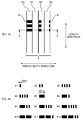
- Fig. 1 is a perspective view of an optical fiber ribbon 1 according to the present embodiment.
- Fig. 2A is a plan view of the optical fiber ribbon 1 according to the present embodiment.
- Fig. 2B is a diagram illustrating examples (Identification Nos. 1 to 12) of markings 6.
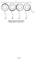
- Fig. 3 is a cross-sectional view of the optical fiber ribbon according to the present embodiment, taken along line A-A.
- Fig. 4 is a diagram illustrating an example of an intermittently connected optical fiber ribbon 1.
- jacketed optical fibers 2 (2A to 2D).
- a "jacketed optical fiber 2" may be referred to simply as an optical fiber.
- a jacketed optical fiber 2 is made by providing a secondary coating on a bare optical fiber.
- a "jacketed optical fiber 2" may be referred to as a primary-coated optical fiber.
- the optical fiber ribbon 1 of the present embodiment includes: four jacketed optical fibers 2A to 2D arranged side by side; and connection parts 6 that each connect two adjacent ones of the jacketed optical fibers 2.
- connection parts 6 that each connect two adjacent ones of the jacketed optical fibers 2.
- Fig. 4 (note that markings 6 are omitted from Fig. 4 to illustrate the connection parts 3)
- a plurality of connection parts 3 are arranged intermittently in the length direction.
- the plurality of connection parts 3 of the optical fiber ribbon 1 are arranged intermittently and two-dimensionally in the length direction and the ribbon's width direction.
- connection parts 3 connect two adjacent jacketed optical fibers 2 by, e.g., an ultraviolet-curable resin or a thermoplastic resin. Regions other than the connection parts 3 between the two adjacent jacketed optical fibers 2 constitute non-connected parts 8. In the non-connected parts 8, the two adjacent jacketed optical fibers 2 are not restrained. Thus, the optical fiber ribbon 1 can be rolled up into a cylindrical form (a bundle), or folded up, and the multitude of jacketed optical fibers 2 can be bundled with high density.
- the intermittently connected optical fiber ribbon 1 is not limited to the example illustrated in Figs. 1 to 4 .
- the number of jacketed optical fibers 2 constituting the intermittently connected optical fiber ribbon 1 may be changed (e.g., to eight fibers or twelve fibers).
- the arrangement of the connection parts 3 may be changed.
- Markings 6 are provided for identifying/distinguishing a certain optical fiber ribbon from other optical fiber ribbons.
- the size (width) of each marking 6 is about 3 to 30 mm in the length direction of the jacketed optical fiber 2.
- a plurality of markings 6 are printed as a set.
- the optical fiber ribbon is identified by the number of markings 6.
- the width of the markings 6 does not have to be the same; for example, as illustrated in Fig. 2B , marks with different widths may be used in combination.
- the marking 6 may have a wavy form.
- the color of the markings 6 does not have to be the same, and markings with different colors may be used in combination.
- the position, in the optical fiber's circumferential direction, of the marking 6 provided to at least one of the jacketed optical fibers 2 is different from the position, in the optical fiber's circumferential direction, of the marking 6 provided to another jacketed optical fiber 2. More specifically, as illustrated in the figures, the markings 6 provided to the respective jacketed optical fibers 2A to 2D are positioned so that they face different directions in terms of the circumferential direction. Herein, the markings 6 on the respective jacketed optical fibers 2A to 2D are not positioned uniformly in the circumferential direction, but are arranged randomly.
- the position, in the circumferential direction, of the marking 6 provided to at least one of the jacketed optical fibers 2 is different from the position, in the circumferential direction, of the marking 6 provided to another jacketed optical fiber 2. Therefore, even in cases where a marking 6 of a certain jacketed optical fiber 2 is blocked by adjacent jacketed optical fibers 2 and is difficult to observe, the marking 6 on another jacketed optical fiber 2 can be visually recognized. Thus, the identifiability of the optical fiber ribbon 1 can be improved.
- the markings 6 on the optical fibers 2A, 2B, and 2D can be visually recognized.
- the marking 6 on the optical fiber 2C can be visually recognized.
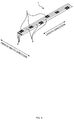
- Fig. 5A is a perspective view of a 12-fiber optical fiber ribbon 1.
- Fig. 5B is a perspective view when the 12-fiber optical fiber ribbon 1 is bundled up.
- Figs. 5A and 5B illustrate a 12-fiber optical fiber ribbon 1 instead of the aforementioned 4-fiber optical fiber ribbon 1.
- Fig. 5A illustrates a state in which the optical fiber ribbon 1--in which the positions, in the circumferential direction, of the respective markings 6 lack unity--is bundled up. Because the positions, in the circumferential direction, of the respective markings 6 are random, the markings 6 on some of the jacketed optical fibers 2 can be visually recognized from the periphery, even when the optical fiber ribbon 1 is bundled up.
- Fig. 6A is a perspective view of an optical fiber ribbon 1' according to a reference example.
- Fig. 6B is a perspective view when the optical fiber ribbon 1' according to the reference example is bundled up.
- Figs. 6A and 6B also illustrate a 12-fiber optical fiber ribbon 1' in order to clearly indicate the difference from the present embodiment.
- Fig. 6B illustrates a state in which this optical fiber ribbon 1' is bundled up such that the ribbon's upper surface faces inward.
- the positions of the markings 6' are uniform and face only toward the upper surface side, it is absolutely impossible, or extremely difficult, to visually recognize the markings 6' when the ribbon is bundled up such that the upper surface faces inward.
- visual recognizability is less likely to be impaired even when the optical fiber ribbon 1 is bundled up.
- the present embodiment describes an example of a jacketed optical fiber 2 in which three markings 6 are printed as a set, the number of markings 6 is not limited thereto.
- the optical fiber ribbons may be made distinguishable from one another by varying the shapes of the markings among optical fiber ribbons.
- Fig. 7 is a diagram illustrating the circumferential angle of a marking 6.
- Fig. 7 illustrates a cross section of a single optical fiber 2. The figure also illustrates a marking 6 and a colored layer 7 of the optical fiber 2, and also illustrates the marking 6's circumferential angle ⁇ from the center of the optical fiber 2.
- the circumferential angle ⁇ is preferably about 100 to 120 degrees, but may be smaller.
- the circumferential angle ⁇ may be within a range from 60 to 70 degrees.
- a colored layer 7 is formed on each jacketed optical fiber 2.
- the colored layers 7 of the respective jacketed optical fibers 2A to 2D are formed so as to have different colors from one another.
- the marking 6 is formed under the colored layer 7. In this way, the marking 6 is protected by the colored layer 7, and thus, the marking 6 can be made less prone to come off.
- Fig. 8 is a diagram illustrating how the markings 6 are arranged.
- Fig. 8 illustrates an example of a distance Lm between markings 6, and a distance Lc between connection parts 3.
- the distance Lm between markings 6 is greater than the distance Lc between connection parts 3.
- the distance Lm between markings 6 may be about 150 mm, and the distance Lc between connection parts 3 may be about 40 mm to 100 mm.
- the positions of the markings 6 formed on the respective jacketed optical fibers 2A to 2D substantially match one another in the length direction of the jacketed optical fibers 2.
- the positions of the connection parts 3 are varied in the length direction of the respective jacketed optical fibers 2A to 2D.
- Fig. 8 also illustrates that, in a certain one of the jacketed optical fibers 2, a plurality of markings 6 provided respectively at different positions in the length direction of the certain jacketed optical fiber 2 are formed respectively at different positions in the circumferential direction. In this way, the positions of the markings 6 in the circumferential direction can be made more random.
- the positions, in the circumferential direction, of adjacent markings 6 are to be arranged randomly.
- the circumferential-direction arrangement does not necessarily have to be random. It is only necessary that the position, in the circumferential direction, of the marking 6 provided to at least one of the jacketed optical fibers 2 is different from the position, in the circumferential direction, of the marking 6 provided to another jacketed optical fiber 2. In this way, even in cases where a marking 6 of a certain jacketed optical fiber 2 is blocked by adjacent jacketed optical fibers 2 and is difficult to observe, the marking 6 on another jacketed optical fiber 2 can be visually recognized. Thus, the identifiability of the optical fiber ribbon 1 can be improved.
- Fig. 9 is a diagram illustrating steps for producing an optical fiber ribbon 1 according to the present embodiment.
- the figure illustrates a feeding device 11, a printing unit 12, a coloring unit 13, a color curing unit 14, a ribbon-forming unit 15, a ribbon curing unit 16, and a take-up drum 17 which are used in the steps for producing the optical fiber ribbon 1.
- the feeding device 11 includes feeding drums 11A to 11D on which the jacketed optical fibers 2A to 2D are respectively wound.
- the number of feeding drums 11A to 11D matches the number of jacketed optical fibers 2A to 2D included in the optical fiber ribbon 1; thus, in this example, four feeding drums 11A to 11D are provided.
- the feeding drums 11A to 11D feed the four jacketed optical fibers 2A to 2D, respectively.
- the printing unit 12 prints the aforementioned markings 6 on a portion, in the jacketed optical fiber's length direction, of the respective four jacketed optical fibers 2A to 2D fed out from the respective feeding devices 11A to 11D.
- an inkjet printer may be employed for the printing unit 6, but it is more preferable to employ a printing device that transfers an ink from a roller respectively to the plurality of jacketed optical fibers, because printing can be performed simultaneously to a plurality of jacketed optical fibers at high speed with a single printing device.
- the printing unit 6 does not print the marking 6 to the entire circumference, in the circumferential direction, of each jacketed optical fiber 2, but prints the marking only on one side.
- the markings 6 of the respective four jacketed optical fibers 2A to 2D face the same direction in the circumferential direction.
- the coloring unit 13 applies coloring agents having different colors from one another to the respective four jacketed optical fibers 2A to 2D.
- Ultraviolet-curable resin is employed for the coloring agents. For example, blue, white, yellow, and gray ultraviolet-curable resins are applied respectively to the four optical fibers.
- optical fiber ribbons 1 are identified/distinguished from one another by the markings 6, whereas the jacketed optical fibers in a single optical fiber ribbon 1 are distinguished from one another by the color of the respective colored layer.
- the printing unit 12 is arranged upstream of the coloring unit 13 in the transporting direction of the jacketed optical fibers 2 is because it is difficult to perform printing after coloring. If the markings 6 were to be printed after coloring, the markings 6 would slightly protrude in the radial direction of each jacketed optical fiber 2. Such protrusions may get snagged on various sliding parts in the production steps described below, which may lead to production defects. In contrast, by forming the colored layer 7 after printing the markings 6, no protrusions are created, and thus, the possibility of production defects can be reduced significantly. Also, in this way, the markings 6 can be protected by the colored layer 7.
- the distance from the printing unit 12 to the ribbon-forming unit 15 can be increased.
- the amount of rotation of each optical fiber can be increased--and thus the position of the marking 6 can be further shifted in the circumferential direction--until each optical fiber reaches the ribbon-forming unit 15.
- the positions of the respective markings 6 can be made more random among the plurality of jacketed optical fibers 2.
- the positions, in the circumferential direction, of respective markings 6 in a single jacketed optical fiber 2 can be made more random.
- the color curing unit 14 irradiates the ultraviolet-curable resin applied by the aforementioned coloring unit 13 with ultraviolet rays, and cures the resin.
- the ribbon-forming unit 15 applies ultraviolet-curable resin between adjacent jacketed optical fibers 2 at predetermined intervals in the length direction of the jacketed optical fibers 2, in order to form the aforementioned connection parts 3.
- the jacketed optical fibers 2A to 2D provided with the ultraviolet-curable resin pass through the ribbon curing unit 16.
- the ribbon curing unit 16 irradiates the uncured connection parts 3 with ultraviolet rays, and cures the ultraviolet-curable resin in the connection parts 3.
- the positions of the markings are shifted randomly in the circumferential direction.
- the connection parts 3 are cured by the ribbon-forming unit 15, the position, in the circumferential direction, of the marking 6 provided to at least one of the jacketed optical fibers 2 is made different from the position, in the circumferential direction, of the marking 6 provided to another jacketed optical fiber 2.
- the optical fiber ribbon 1 produced as above is taken up by the take-up drum 17.
- the optical fiber ribbon 1 is taken up by a single take-up drum 17.
- tension applied to the jacketed optical fibers 2A to 2D is applied by the take-up drum 17; because a single take-up drum 17 takes up the four jacketed optical fibers 2A to 2D, the tension applied to each of these jacketed optical fibers is substantially the same.
- the jacketed optical fibers 2A to 2D are transported downstream at substantially the same speed.
- the positions of the markings 6 on the respective jacketed optical fibers 2A to 2D are all located at substantially the same position in the length direction of the optical fiber ribbon 1, even when they are taken up as an optical fiber ribbon 1.
- each of the jacketed optical fibers 2 is transported while rotating clockwise or counterclockwise about its core. This occurs because of, e.g., force produced by the uncurling of the jacketed optical fibers 2 when they are fed out from the respective feeding drums 11, and individual variations among the production devices used for applying the aforementioned production steps to the four jacketed optical fibers 2A to 2D. Another reason is considered to be the difference in force applied to the respective jacketed optical fibers 2 when the jacketed optical fibers 2--which were separate from one another in the color curing unit 14--are gathered together in the ribbon-forming unit 15.
- the markings 6 are printed on the four jacketed optical fibers 2 so as to face the same direction in the circumferential direction.
- each jacketed optical fiber 2 separately undergoes individual rotational displacement.
- the four jacketed optical fibers 2 separately rotate in the circumferential direction by different amounts.
- the position, in the circumferential direction, of the marking 6 provided to at least one of the jacketed optical fibers 2 becomes different from the position, in the circumferential direction, of the marking 6 provided to another jacketed optical fiber 2.
- the jacketed optical fibers 2 were made to rotate separately in the circumferential direction by different amounts by employing the curling created in the fibers by the feeding drums, individual variations among devices, and the difference in force applied to the jacketed optical fibers 2, as described above.
- Fig. 10 is a diagram illustrating an optical fiber cable according to the present embodiment.
- An optical fiber cable 10 can be produced by: gathering a plurality of optical fiber ribbons 1 produced by the aforementioned production steps; winding a wrapping tape 4 around the ribbons; and covering the wrapping tape 4 with a sheath 5. Even when a plurality of optical fiber ribbons 1 are gathered together, the optical fiber ribbons 1 can be distinguished from one another because the respective optical fiber ribbons have different numbers of markings 6.
- the position, in the circumferential direction, of the marking provided to at least one of the jacketed optical fibers 2 is different from the position, in the circumferential direction, of the marking provided to another jacketed optical fiber. Therefore, even in cases where a marking of a certain jacketed optical fiber is blocked by adjacent optical fibers and is difficult to observe, the marking on another jacketed optical fiber can be visually recognized. Thus, the identifiability of the optical fiber ribbon 1 can be improved.
Landscapes
- Physics & Mathematics (AREA)
- General Physics & Mathematics (AREA)
- Optics & Photonics (AREA)
- Engineering & Computer Science (AREA)
- Manufacturing & Machinery (AREA)
- Optical Fibers, Optical Fiber Cores, And Optical Fiber Bundles (AREA)
Abstract
Description
- The present invention relates to an optical fiber ribbon provided with markings.
- Markings are provided to optical fibers of an optical fiber ribbon in order to identify a specific optical fiber ribbon from among a plurality of optical fiber ribbons.
Patent Literature 1 discloses an optical fiber ribbon in which a marking is provided such that the marking substantially makes a full round around the circumferential surface of an optical fiber.Patent Literature 2 discloses an optical fiber ribbon in which a marking is provided only to a portion, in the circumferential direction, of a cover layer. -
- Patent Literature 1:
JP 2013-88619A - Patent Literature 2:
JP 2012-173603A - In the optical fiber ribbon disclosed in
Patent Literature 1, the outer diameter of each optical fiber is increased at the marking section. This increase in diameter may heighten the possibility of an increase in optical transmission loss caused by distortion, and may also heighten the possibility of clogging/blocking etc. in a die during the steps for coloring and/or ribbon-forming. Moreover, it is difficult to produce an optical fiber ribbon while printing markings to substantially the entire circumferential surface of the respective optical fibers. Even if it were possible to provide markings to the entire circumference of the respective optical fibers, there would be an increase in the amount of ink used. - On the other hand, in cases where a marking is provided only partially in the circumferential direction as in the optical fiber ribbon disclosed in
Patent Literature 2, the marking cannot be visually recognized, for example, when viewed from the opposite side from where the marking is provided. This may impair the identifiability of the optical fiber ribbon. - An objective of the invention is to improve identifiability of optical fiber ribbons.
- A primary aspect of the invention for achieving the aforementioned objective is an optical fiber ribbon including: at least three optical fibers arranged side by side; and a plurality of connection parts that each connect two adjacent ones of the optical fibers, the connection parts being provided intermittently in a length direction of the optical fibers and in a width direction of the optical fibers. A marking for identifying the optical fiber ribbon is provided to each optical fiber. The position, in the optical fiber's circumferential direction, of the marking provided to at least one of the optical fibers is different from the position, in the optical fiber's circumferential direction, of the marking provided to another optical fiber.
- Other features of the invention are disclosed in the following Description and Drawings.
- The present invention can improve identifiability of optical fiber ribbons.
-
- [
Fig. 1] Fig. 1 is a perspective view of anoptical fiber ribbon 1 according to an embodiment. - [
Fig. 2] Fig. 2A is a plan view of anoptical fiber ribbon 1 according to an embodiment.Fig. 2B is a diagram illustrating examples (Identification Nos. 1 to 12) ofmarkings 6. - [
Fig. 3] Fig. 3 is a cross-sectional view of an optical fiber ribbon according to an embodiment, taken along line A-A. - [
Fig. 4] Fig. 4 is a diagram illustrating an example of an intermittently connectedoptical fiber ribbon 1. - [
Fig. 5] Fig. 5A is a perspective view of a 12-fiberoptical fiber ribbon 1.Fig. 5B is a perspective view when the 12-fiberoptical fiber ribbon 1 is bundled up. - [
Fig. 6] Fig. 6A is a perspective view of an optical fiber ribbon 1' according to a reference example.Fig. 6B is a perspective view when the optical fiber ribbon 1' according to the reference example is bundled up. - [
Fig. 7] Fig. 7 is a diagram illustrating the circumferential angle of amarking 6. - [
Fig. 8] Fig. 8 is a diagram illustrating howmarkings 6 are arranged. - [
Fig. 9] Fig. 9 is a diagram illustrating steps for producing anoptical fiber ribbon 1 according to an embodiment. - [
Fig. 10] Fig. 10 is a diagram illustrating anoptical fiber cable 10 according to an embodiment. - At least the following matters are disclosed in the Description and Drawings below.
- Disclosed is an optical fiber ribbon including: at least three optical fibers arranged side by side; and a plurality of connection parts that each connect two adjacent ones of the optical fibers, the connection parts being provided intermittently in a length direction of the optical fibers and in a width direction of the optical fibers. A marking for identifying the optical fiber ribbon is provided to each optical fiber. The position, in the optical fiber's circumferential direction, of the marking provided to at least one of the optical fibers is different from the position, in the optical fiber's circumferential direction, of the marking provided to another optical fiber.
- According to the aforementioned optical fiber ribbon, the position, in the circumferential direction, of the marking provided to at least one of the optical fibers is different from the position, in the circumferential direction, of the marking provided to another optical fiber. Therefore, even in cases where a marking of a certain optical fiber is blocked by adjacent optical fibers and is difficult to observe, the marking on another optical fiber can be visually recognized. Thus, the identifiability of the optical fiber ribbon can be improved.
- It is preferable that: a plurality of the markings are provided respectively at different positions in the length direction of a certain one of the optical fibers; and the markings of the certain optical fiber are formed respectively at different positions in the circumferential direction. In this way, it is possible to make the position, in the circumferential direction, of the marking provided to at least one of the optical fibers different from the position, in the circumferential direction, of the marking provided to another optical fiber.
- It is preferable that: a colored layer is formed on each of the optical fibers, the colored layers of the respective optical fibers having different colors from one another; and each marking is formed under the colored layer. In this way, the marking is protected by the colored layer, and thus, the marking can be made less prone to come off.
- Also disclosed is an optical fiber cable made by covering a plurality of the aforementioned optical fiber ribbons with a sheath. Thus, it is possible to provide an optical fiber cable including optical fiber ribbons having improved identifiability.
- Also disclosed is a method for producing an optical fiber ribbon, the method involving: a printing step of printing a marking for identifying the optical fiber ribbon to a portion, in a length direction, of an optical fiber; and a ribbon-forming step of forming the optical fiber ribbon by intermittently applying a resin to a plurality of the optical fibers and curing the resin in a state where a position, in the optical fiber's circumferential direction, of the marking provided to at least one of the optical fibers is made different from a position, in the optical fiber's circumferential direction, of the marking provided to another optical fiber.
- According to an optical fiber ribbon produced by the aforementioned production method, the position, in the circumferential direction, of the marking provided to at least one of the optical fibers is different from the position, in the circumferential direction, of the marking provided to another optical fiber. Therefore, even in cases where a marking of a certain optical fiber is blocked by adjacent optical fibers and is difficult to observe, the marking on another optical fiber can be visually recognized. Thus, the identifiability of the optical fiber ribbon can be improved.
- It is preferable that, in the printing step, the markings are printed by transferring an ink from a roller respectively to a plurality of the optical fibers. In this way, markings can be printed respectively onto a plurality of optical fibers at high speed.
-
Fig. 1 is a perspective view of anoptical fiber ribbon 1 according to the present embodiment.Fig. 2A is a plan view of theoptical fiber ribbon 1 according to the present embodiment.Fig. 2B is a diagram illustrating examples (Identification Nos. 1 to 12) ofmarkings 6.Fig. 3 is a cross-sectional view of the optical fiber ribbon according to the present embodiment, taken along line A-A.Fig. 4 is a diagram illustrating an example of an intermittently connectedoptical fiber ribbon 1. - These figures illustrate jacketed optical fibers 2 (2A to 2D). However, a "jacketed
optical fiber 2" may be referred to simply as an optical fiber. A jacketedoptical fiber 2 is made by providing a secondary coating on a bare optical fiber. Alternatively, a "jacketedoptical fiber 2" may be referred to as a primary-coated optical fiber. - As illustrated in these figures, the
optical fiber ribbon 1 of the present embodiment includes: four jacketedoptical fibers 2A to 2D arranged side by side; andconnection parts 6 that each connect two adjacent ones of the jacketedoptical fibers 2. As illustrated inFig. 4 (note thatmarkings 6 are omitted fromFig. 4 to illustrate the connection parts 3), between two adjacent jacketedoptical fibers 2, a plurality ofconnection parts 3 are arranged intermittently in the length direction. The plurality ofconnection parts 3 of theoptical fiber ribbon 1 are arranged intermittently and two-dimensionally in the length direction and the ribbon's width direction. - The
connection parts 3 connect two adjacent jacketedoptical fibers 2 by, e.g., an ultraviolet-curable resin or a thermoplastic resin. Regions other than theconnection parts 3 between the two adjacent jacketedoptical fibers 2 constitutenon-connected parts 8. In thenon-connected parts 8, the two adjacent jacketedoptical fibers 2 are not restrained. Thus, theoptical fiber ribbon 1 can be rolled up into a cylindrical form (a bundle), or folded up, and the multitude of jacketedoptical fibers 2 can be bundled with high density. - The intermittently connected
optical fiber ribbon 1 is not limited to the example illustrated inFigs. 1 to 4 . For example, the number of jacketedoptical fibers 2 constituting the intermittently connectedoptical fiber ribbon 1 may be changed (e.g., to eight fibers or twelve fibers). Also, the arrangement of theconnection parts 3 may be changed. -
Markings 6 are provided for identifying/distinguishing a certain optical fiber ribbon from other optical fiber ribbons. The size (width) of each marking 6 is about 3 to 30 mm in the length direction of the jacketedoptical fiber 2. A plurality ofmarkings 6 are printed as a set. The optical fiber ribbon is identified by the number ofmarkings 6. The width of themarkings 6 does not have to be the same; for example, as illustrated inFig. 2B , marks with different widths may be used in combination. The marking 6 may have a wavy form. The color of themarkings 6 does not have to be the same, and markings with different colors may be used in combination. - The position, in the optical fiber's circumferential direction, of the marking 6 provided to at least one of the jacketed
optical fibers 2 is different from the position, in the optical fiber's circumferential direction, of the marking 6 provided to another jacketedoptical fiber 2. More specifically, as illustrated in the figures, themarkings 6 provided to the respective jacketedoptical fibers 2A to 2D are positioned so that they face different directions in terms of the circumferential direction. Herein, themarkings 6 on the respective jacketedoptical fibers 2A to 2D are not positioned uniformly in the circumferential direction, but are arranged randomly. - According to this
optical fiber ribbon 1, the position, in the circumferential direction, of the marking 6 provided to at least one of the jacketedoptical fibers 2 is different from the position, in the circumferential direction, of the marking 6 provided to another jacketedoptical fiber 2. Therefore, even in cases where a marking 6 of a certain jacketedoptical fiber 2 is blocked by adjacent jacketedoptical fibers 2 and is difficult to observe, the marking 6 on another jacketedoptical fiber 2 can be visually recognized. Thus, the identifiability of theoptical fiber ribbon 1 can be improved. - For example, even in cases where there is an optical fiber whose marking 6 cannot be visually recognized at all, like the
optical fiber 2C inFig. 2A , themarkings 6 on theoptical fibers Fig. 2A , the marking 6 on theoptical fiber 2C can be visually recognized. -
Fig. 5A is a perspective view of a 12-fiberoptical fiber ribbon 1.Fig. 5B is a perspective view when the 12-fiberoptical fiber ribbon 1 is bundled up. In order to demonstrate the effect of the present embodiment more clearly,Figs. 5A and 5B illustrate a 12-fiberoptical fiber ribbon 1 instead of the aforementioned 4-fiberoptical fiber ribbon 1. - The positions, in the circumferential direction, of the
respective markings 6 on each of the jacketedoptical fibers 2 of theoptical fiber ribbon 1 illustrated inFig. 5A are random, and completely lack unity.Fig. 5B illustrates a state in which theoptical fiber ribbon 1--in which the positions, in the circumferential direction, of therespective markings 6 lack unity--is bundled up. Because the positions, in the circumferential direction, of therespective markings 6 are random, themarkings 6 on some of the jacketedoptical fibers 2 can be visually recognized from the periphery, even when theoptical fiber ribbon 1 is bundled up. -
Fig. 6A is a perspective view of an optical fiber ribbon 1' according to a reference example.Fig. 6B is a perspective view when the optical fiber ribbon 1' according to the reference example is bundled up.Figs. 6A and 6B also illustrate a 12-fiber optical fiber ribbon 1' in order to clearly indicate the difference from the present embodiment. - In the optical fiber ribbon 1' of the reference example, the markings 6' are provided only on the upper surface side of the respective jacketed
optical fibers 2.Fig. 6B illustrates a state in which this optical fiber ribbon 1' is bundled up such that the ribbon's upper surface faces inward. As illustrated in the figure, because the positions of the markings 6' are uniform and face only toward the upper surface side, it is absolutely impossible, or extremely difficult, to visually recognize the markings 6' when the ribbon is bundled up such that the upper surface faces inward. In contrast, according to theoptical fiber ribbon 1 of the present embodiment as illustrated inFigs. 5A and 5B , visual recognizability is less likely to be impaired even when theoptical fiber ribbon 1 is bundled up. - It should be noted that, although the present embodiment describes an example of a jacketed
optical fiber 2 in which threemarkings 6 are printed as a set, the number ofmarkings 6 is not limited thereto. Other than by varying the number ofmarkings 6, the optical fiber ribbons may be made distinguishable from one another by varying the shapes of the markings among optical fiber ribbons. -
Fig. 7 is a diagram illustrating the circumferential angle of amarking 6.Fig. 7 illustrates a cross section of a singleoptical fiber 2. The figure also illustrates amarking 6 and acolored layer 7 of theoptical fiber 2, and also illustrates the marking 6's circumferential angle α from the center of theoptical fiber 2. - In the present embodiment, the circumferential angle α is preferably about 100 to 120 degrees, but may be smaller. For example, the circumferential angle α may be within a range from 60 to 70 degrees.
- As illustrated in
Fig. 7 , acolored layer 7 is formed on each jacketedoptical fiber 2. Thecolored layers 7 of the respective jacketedoptical fibers 2A to 2D are formed so as to have different colors from one another. The marking 6 is formed under thecolored layer 7. In this way, the marking 6 is protected by thecolored layer 7, and thus, the marking 6 can be made less prone to come off. -
Fig. 8 is a diagram illustrating how themarkings 6 are arranged.Fig. 8 illustrates an example of a distance Lm betweenmarkings 6, and a distance Lc betweenconnection parts 3. In the present embodiment, the distance Lm betweenmarkings 6 is greater than the distance Lc betweenconnection parts 3. For example, the distance Lm betweenmarkings 6 may be about 150 mm, and the distance Lc betweenconnection parts 3 may be about 40 mm to 100 mm. - As a matter of course, the positions of the
markings 6 formed on the respective jacketedoptical fibers 2A to 2D substantially match one another in the length direction of the jacketedoptical fibers 2. On the other hand, the positions of theconnection parts 3 are varied in the length direction of the respective jacketedoptical fibers 2A to 2D. -
Fig. 8 also illustrates that, in a certain one of the jacketedoptical fibers 2, a plurality ofmarkings 6 provided respectively at different positions in the length direction of the certain jacketedoptical fiber 2 are formed respectively at different positions in the circumferential direction. In this way, the positions of themarkings 6 in the circumferential direction can be made more random. - The above describes that the positions, in the circumferential direction, of
adjacent markings 6 are to be arranged randomly. However, the circumferential-direction arrangement does not necessarily have to be random. It is only necessary that the position, in the circumferential direction, of the marking 6 provided to at least one of the jacketedoptical fibers 2 is different from the position, in the circumferential direction, of the marking 6 provided to another jacketedoptical fiber 2. In this way, even in cases where a marking 6 of a certain jacketedoptical fiber 2 is blocked by adjacent jacketedoptical fibers 2 and is difficult to observe, the marking 6 on another jacketedoptical fiber 2 can be visually recognized. Thus, the identifiability of theoptical fiber ribbon 1 can be improved. -
Fig. 9 is a diagram illustrating steps for producing anoptical fiber ribbon 1 according to the present embodiment. The figure illustrates afeeding device 11, aprinting unit 12, acoloring unit 13, acolor curing unit 14, a ribbon-formingunit 15, aribbon curing unit 16, and a take-up drum 17 which are used in the steps for producing theoptical fiber ribbon 1. - The
feeding device 11 includes feedingdrums 11A to 11D on which the jacketedoptical fibers 2A to 2D are respectively wound. The number of feedingdrums 11A to 11D matches the number of jacketedoptical fibers 2A to 2D included in theoptical fiber ribbon 1; thus, in this example, four feedingdrums 11A to 11D are provided. The feedingdrums 11A to 11D feed the four jacketedoptical fibers 2A to 2D, respectively. - The
printing unit 12 prints theaforementioned markings 6 on a portion, in the jacketed optical fiber's length direction, of the respective four jacketedoptical fibers 2A to 2D fed out from therespective feeding devices 11A to 11D. For example, an inkjet printer may be employed for theprinting unit 6, but it is more preferable to employ a printing device that transfers an ink from a roller respectively to the plurality of jacketed optical fibers, because printing can be performed simultaneously to a plurality of jacketed optical fibers at high speed with a single printing device. - The
printing unit 6 does not print themarking 6 to the entire circumference, in the circumferential direction, of each jacketedoptical fiber 2, but prints the marking only on one side. Thus, at theprinting unit 12, themarkings 6 of the respective four jacketedoptical fibers 2A to 2D face the same direction in the circumferential direction. - The
coloring unit 13 applies coloring agents having different colors from one another to the respective four jacketedoptical fibers 2A to 2D. Ultraviolet-curable resin is employed for the coloring agents. For example, blue, white, yellow, and gray ultraviolet-curable resins are applied respectively to the four optical fibers. By applying different coloring agents respectively to the four jacketedoptical fibers 2A to 2D, the jacketedoptical fibers 2A to 2D in a singleoptical fiber ribbon 1 can be distinguished from one another. - As described above,
optical fiber ribbons 1 are identified/distinguished from one another by themarkings 6, whereas the jacketed optical fibers in a singleoptical fiber ribbon 1 are distinguished from one another by the color of the respective colored layer. - One of the reasons that the
printing unit 12 is arranged upstream of thecoloring unit 13 in the transporting direction of the jacketedoptical fibers 2 is because it is difficult to perform printing after coloring. If themarkings 6 were to be printed after coloring, themarkings 6 would slightly protrude in the radial direction of each jacketedoptical fiber 2. Such protrusions may get snagged on various sliding parts in the production steps described below, which may lead to production defects. In contrast, by forming thecolored layer 7 after printing themarkings 6, no protrusions are created, and thus, the possibility of production defects can be reduced significantly. Also, in this way, themarkings 6 can be protected by thecolored layer 7. - Also, by arranging the
printing unit 12 on the upstream side, the distance from theprinting unit 12 to the ribbon-formingunit 15 can be increased. By increasing the distance from theprinting unit 12 to the ribbon-formingunit 15, the amount of rotation of each optical fiber can be increased--and thus the position of the marking 6 can be further shifted in the circumferential direction--until each optical fiber reaches the ribbon-formingunit 15. Thus, the positions of therespective markings 6 can be made more random among the plurality of jacketedoptical fibers 2. Also, the positions, in the circumferential direction, ofrespective markings 6 in a single jacketedoptical fiber 2 can be made more random. - The
color curing unit 14 irradiates the ultraviolet-curable resin applied by theaforementioned coloring unit 13 with ultraviolet rays, and cures the resin. - The ribbon-forming
unit 15 applies ultraviolet-curable resin between adjacent jacketedoptical fibers 2 at predetermined intervals in the length direction of the jacketedoptical fibers 2, in order to form theaforementioned connection parts 3. The jacketedoptical fibers 2A to 2D provided with the ultraviolet-curable resin pass through theribbon curing unit 16. Theribbon curing unit 16 irradiates theuncured connection parts 3 with ultraviolet rays, and cures the ultraviolet-curable resin in theconnection parts 3. - While the jacketed
optical fibers 2 are transported from theprinting unit 12 to the ribbon-formingunit 15, the positions of the markings are shifted randomly in the circumferential direction. As a result, when theconnection parts 3 are cured by the ribbon-formingunit 15, the position, in the circumferential direction, of the marking 6 provided to at least one of the jacketedoptical fibers 2 is made different from the position, in the circumferential direction, of the marking 6 provided to another jacketedoptical fiber 2. - The
optical fiber ribbon 1 produced as above is taken up by the take-up drum 17. Theoptical fiber ribbon 1 is taken up by a single take-up drum 17. Thus, tension applied to the jacketedoptical fibers 2A to 2D is applied by the take-up drum 17; because a single take-up drum 17 takes up the four jacketedoptical fibers 2A to 2D, the tension applied to each of these jacketed optical fibers is substantially the same. Thus, even after the formation of themarkings 6 on the respective jacketedoptical fibers 2A to 2D, the jacketedoptical fibers 2A to 2D are transported downstream at substantially the same speed. Thus, the positions of themarkings 6 on the respective jacketedoptical fibers 2A to 2D are all located at substantially the same position in the length direction of theoptical fiber ribbon 1, even when they are taken up as anoptical fiber ribbon 1. - On the other hand, during the course in which the jacketed
optical fibers 2A to 2D are fed out from therespective feeding drums 11A to 11D and reach the ribbon-formingunit 15 while undergoing various steps, each of the jacketedoptical fibers 2 is transported while rotating clockwise or counterclockwise about its core. This occurs because of, e.g., force produced by the uncurling of the jacketedoptical fibers 2 when they are fed out from the respective feeding drums 11, and individual variations among the production devices used for applying the aforementioned production steps to the four jacketedoptical fibers 2A to 2D. Another reason is considered to be the difference in force applied to the respective jacketedoptical fibers 2 when the jacketedoptical fibers 2--which were separate from one another in thecolor curing unit 14--are gathered together in the ribbon-formingunit 15. - In the
printing unit 12, themarkings 6 are printed on the four jacketedoptical fibers 2 so as to face the same direction in the circumferential direction. However, due to the aforementioned mechanical action occurring in the circumferential direction, each jacketedoptical fiber 2 separately undergoes individual rotational displacement. Also, because there is a long distance until the jacketedoptical fibers 2 reach the ribbon-formingunit 15, the four jacketedoptical fibers 2 separately rotate in the circumferential direction by different amounts. Thus, when the optical fibers reach the ribbon-formingunit 15, the position, in the circumferential direction, of the marking 6 provided to at least one of the jacketedoptical fibers 2 becomes different from the position, in the circumferential direction, of the marking 6 provided to another jacketedoptical fiber 2. - In the present example, the jacketed
optical fibers 2 were made to rotate separately in the circumferential direction by different amounts by employing the curling created in the fibers by the feeding drums, individual variations among devices, and the difference in force applied to the jacketedoptical fibers 2, as described above. However, it is instead possible to provide a device that makes the jacketedoptical fibers 2A to 2D rotate separately in the circumferential direction by different amounts, and rotationally displace each of the jacketedoptical fibers 2 actively in the circumferential direction by different amounts. -
Fig. 10 is a diagram illustrating an optical fiber cable according to the present embodiment. Anoptical fiber cable 10 can be produced by: gathering a plurality ofoptical fiber ribbons 1 produced by the aforementioned production steps; winding awrapping tape 4 around the ribbons; and covering thewrapping tape 4 with asheath 5. Even when a plurality ofoptical fiber ribbons 1 are gathered together, theoptical fiber ribbons 1 can be distinguished from one another because the respective optical fiber ribbons have different numbers ofmarkings 6. - As regards the
optical fiber ribbon 1, the position, in the circumferential direction, of the marking provided to at least one of the jacketedoptical fibers 2 is different from the position, in the circumferential direction, of the marking provided to another jacketed optical fiber. Therefore, even in cases where a marking of a certain jacketed optical fiber is blocked by adjacent optical fibers and is difficult to observe, the marking on another jacketed optical fiber can be visually recognized. Thus, the identifiability of theoptical fiber ribbon 1 can be improved. - The foregoing embodiments are for facilitating the understanding of the present invention, and are not to be construed as limiting the present invention. The present invention may be modified and/or improved without departing from the gist thereof, and it goes without saying that the present invention encompasses any equivalents thereof.
-
- 1:
- Optical fiber ribbon;
- 2:
- Jacketed optical fiber;
- 3:
- Connection part;
- 4:
- Wrapping tape;
- 5:
- Sheath;
- 6:
- Marking;
- 7:
- Colored layer;
- 8:
- Non-connected part;
- 10:
- Optical fiber cable;
- 11:
- Feeding device;
- 12:
- Printing unit;
- 13:
- Coloring unit;
- 14:
- Color curing unit;
- 15:
- Ribbon-forming unit;
- 16:
- Ribbon curing unit;
- 17:
- Take-up drum.
Claims (6)
- An optical fiber ribbon comprising:at least three optical fibers arranged side by side; anda plurality of connection parts that each connect two adjacent ones of the optical fibers, the connection parts being provided intermittently in a length direction of the optical fibers and in a width direction of the optical fibers, wherein:a marking for identifying the optical fiber ribbon is provided to each optical fiber; anda position, in the optical fiber's circumferential direction, of the marking provided to at least one of the optical fibers is different from a position, in the optical fiber's circumferential direction, of the marking provided to another optical fiber.
- The optical fiber ribbon according to claim 1, wherein:a plurality of the markings are provided respectively at different positions in the length direction of a certain one of the optical fibers; andthe markings of the certain optical fiber are formed respectively at different positions in the circumferential direction.
- The optical fiber ribbon according to claim 1 or 2, wherein:a colored layer is formed on each of the optical fibers, the colored layers of the respective optical fibers having different colors from one another; andeach marking is formed under the colored layer.
- An optical fiber cable made by covering a plurality of the optical fiber ribbons according to any one of claims 1 to 3 with a sheath.
- A method for producing an optical fiber ribbon, the method comprising:a printing step of printing a marking for identifying the optical fiber ribbon to a portion, in a length direction, of an optical fiber; anda ribbon-forming step of forming the optical fiber ribbon by intermittently applying a resin to a plurality of the optical fibers and curing the resin in a state where a position, in the optical fiber's circumferential direction, of the marking provided to at least one of the optical fibers is made different from a position, in the optical fiber's circumferential direction, of the marking provided to another optical fiber.
- The method for producing an optical fiber ribbon according to claim 5, wherein, in the printing step, the markings are printed by transferring an ink from a roller respectively to a plurality of the optical fibers.
Priority Applications (1)
| Application Number | Priority Date | Filing Date | Title |
|---|---|---|---|
| EP21196647.8A EP3943995A1 (en) | 2014-11-20 | 2015-11-05 | Optical fiber ribbon, optical fiber cable, and method for producing optical fiber ribbon |
Applications Claiming Priority (2)
| Application Number | Priority Date | Filing Date | Title |
|---|---|---|---|
| JP2014235500A JP6412779B2 (en) | 2014-11-20 | 2014-11-20 | Optical fiber ribbon, optical fiber cable, and optical fiber ribbon manufacturing method |
| PCT/JP2015/081129 WO2016080195A1 (en) | 2014-11-20 | 2015-11-05 | Optical fiber ribbon, optical fiber cable, and method for manufacturing optical fiber ribbon |
Related Child Applications (1)
| Application Number | Title | Priority Date | Filing Date |
|---|---|---|---|
| EP21196647.8A Division EP3943995A1 (en) | 2014-11-20 | 2015-11-05 | Optical fiber ribbon, optical fiber cable, and method for producing optical fiber ribbon |
Publications (3)
| Publication Number | Publication Date |
|---|---|
| EP3091383A1 true EP3091383A1 (en) | 2016-11-09 |
| EP3091383A4 EP3091383A4 (en) | 2017-10-11 |
| EP3091383B1 EP3091383B1 (en) | 2021-09-15 |
Family
ID=56013746
Family Applications (2)
| Application Number | Title | Priority Date | Filing Date |
|---|---|---|---|
| EP15861486.7A Active EP3091383B1 (en) | 2014-11-20 | 2015-11-05 | Optical fiber ribbon, optical fiber cable, and method for manufacturing optical fiber ribbon |
| EP21196647.8A Withdrawn EP3943995A1 (en) | 2014-11-20 | 2015-11-05 | Optical fiber ribbon, optical fiber cable, and method for producing optical fiber ribbon |
Family Applications After (1)
| Application Number | Title | Priority Date | Filing Date |
|---|---|---|---|
| EP21196647.8A Withdrawn EP3943995A1 (en) | 2014-11-20 | 2015-11-05 | Optical fiber ribbon, optical fiber cable, and method for producing optical fiber ribbon |
Country Status (9)
| Country | Link |
|---|---|
| US (1) | US10185110B2 (en) |
| EP (2) | EP3091383B1 (en) |
| JP (1) | JP6412779B2 (en) |
| CN (1) | CN105917261B (en) |
| AU (1) | AU2015351263B2 (en) |
| CA (1) | CA2930793C (en) |
| ES (1) | ES2892328T3 (en) |
| TW (1) | TWI579612B (en) |
| WO (1) | WO2016080195A1 (en) |
Cited By (1)
| Publication number | Priority date | Publication date | Assignee | Title |
|---|---|---|---|---|
| AT525543B1 (en) * | 2022-05-16 | 2023-05-15 | Medek & Schoerner Gmbh | Fiber optic ribbon and method of making same |
Families Citing this family (36)
| Publication number | Priority date | Publication date | Assignee | Title |
|---|---|---|---|---|
| JP6106253B1 (en) * | 2015-12-04 | 2017-03-29 | 株式会社フジクラ | OPTICAL FIBER TAPE, OPTICAL FIBER TAPE MANUFACTURING METHOD, AND ULTRAVIOLET-CURABLE RESIN COMPOSITION USED FOR FORMING INTERCONNECTION OF INTERNAL FIXED OPTICAL FIBER TAPE |
| AU2016386157A1 (en) * | 2016-01-13 | 2018-07-19 | Sumitomo Electric Industries, Ltd. | Intermittent-connection-type optical fiber tape core, optical cable, and method for manufacturing intermittent-connection-type optical fiber tape core |
| US10989888B2 (en) * | 2016-02-02 | 2021-04-27 | Ofs Fitel, Llc | Flexible ribbon structure and method for making |
| EP3258219A1 (en) * | 2016-06-15 | 2017-12-20 | Eidgenössische Materialprüfungs- und Forschungsanstalt EMPA | In-situ and real time quality control in additive manufacturing process |
| CA3045290A1 (en) * | 2016-11-29 | 2018-06-07 | Corning Optical Communications LLC | Laser sintered flexible ribbon |
| EP3561564B1 (en) * | 2016-12-20 | 2025-07-16 | Furukawa Electric Co., Ltd. | Method for manufacturing optical fiber intermittent tape core and optical fiber intermittent tape core |
| WO2018174004A1 (en) * | 2017-03-21 | 2018-09-27 | 住友電気工業株式会社 | Optical fiber cable |
| EP3602155A1 (en) | 2017-03-21 | 2020-02-05 | Corning Research & Development Corporation | Fiber optic cable assembly with thermoplastically overcoated fusion splice, and related method and apparatus |
| PL3652576T3 (en) | 2017-07-11 | 2022-11-07 | Prysmian S.P.A. | An optical fiber ribbon assembly and a method of producing the same |
| AU2017423261B2 (en) * | 2017-07-11 | 2023-07-20 | Prysmian S.P.A. | An optical fiber ribbon and a method of producing the same |
| WO2019021998A1 (en) * | 2017-07-24 | 2019-01-31 | 住友電気工業株式会社 | Optical fiber ribbon and optical fiber cable |
| EP3665521B1 (en) | 2017-08-08 | 2023-11-08 | Corning Research & Development Corporation | Rollable optical fiber ribbon with low attenuation, large mode field diameter optical fiber and cable |
| US11500171B2 (en) | 2018-01-15 | 2022-11-15 | Prysmian S.P.A. | Optical fiber ribbon and a method and system of producing the same |
| US11256051B2 (en) | 2018-01-15 | 2022-02-22 | Prysmian S.P.A. | Flexible optical-fiber ribbon |
| AU2018401778C1 (en) | 2018-01-15 | 2024-08-08 | Prysmian S.P.A. | A method for producing a flexible optical fiber ribbon and said ribbon. |
| CN112888978B (en) | 2018-09-07 | 2023-01-13 | 康宁公司 | Optical fiber fanout assembly with ribbonized interface for multi-way fusion splicing and method of making same |
| US10976492B2 (en) | 2018-09-07 | 2021-04-13 | Corning Incorporated | Cable with overcoated non-coplanar groups of fusion spliced optical fibers, and fabrication method |
| US11125962B2 (en) * | 2018-12-06 | 2021-09-21 | Sterlite Technologies Limited | Rollable optical fiber ribbon with colour line marking |
| US11287597B2 (en) * | 2019-01-09 | 2022-03-29 | Corning Incorporated | Apparatus and methods for marking optical fibers using an ink stream |
| US11131817B2 (en) | 2019-05-09 | 2021-09-28 | Go!Foton Holdings, Inc. | Multi-fiber cable |
| WO2020250826A1 (en) | 2019-06-11 | 2020-12-17 | 住友電気工業株式会社 | Resin composition, optical fiber secondary coating material, optical fiber and manufacturing method of optical fiber |
| US11360265B2 (en) * | 2019-07-31 | 2022-06-14 | Corning Research & Development Corporation | Fiber optic cable assembly with overlapping bundled strength members, and fabrication method and apparatus |
| JP7426206B2 (en) * | 2019-09-04 | 2024-02-01 | 株式会社フジクラ | Optical fiber tape, optical fiber tape direction identification method and fusion splicing device |
| JP7157026B2 (en) * | 2019-09-12 | 2022-10-19 | 株式会社フジクラ | Optical fiber alignment method, optical fiber fusion splicing method, method for manufacturing optical fiber tape with connector, and intermittent connection type optical fiber tape |
| US10884213B1 (en) * | 2019-11-14 | 2021-01-05 | Prysmian S.P.A. | Optical-fiber ribbon with distorted sinusoidal adhesive pattern and method therefor |
| CN111552042A (en) * | 2020-05-27 | 2020-08-18 | 江苏亨通光电股份有限公司 | Anti-counterfeiting process for optical cable |
| US11886009B2 (en) | 2020-10-01 | 2024-01-30 | Corning Research & Development Corporation | Coating fusion spliced optical fibers and subsequent processing methods thereof |
| EP4237893A4 (en) * | 2020-10-29 | 2025-01-22 | Corning Research & Development Corporation | Intermittently bonded optical fiber ribbon with joining ribbon matrices |
| US11808983B2 (en) | 2020-11-24 | 2023-11-07 | Corning Research & Development Corporation | Multi-fiber splice protector with compact splice-on furcation housing |
| WO2022130855A1 (en) | 2020-12-16 | 2022-06-23 | 住友電気工業株式会社 | Resin composition, secondary coating material for optical fiber, optical fiber, and method for manufacturing optical fiber |
| US11442238B2 (en) | 2020-12-22 | 2022-09-13 | Prysmian S.P.A. | Optical-fiber ribbon with spaced optical-fiber units |
| US11860429B2 (en) | 2020-12-22 | 2024-01-02 | Prysmian S.P.A. | Optical-fiber ribbon with spaced optical-fiber units |
| US11460652B2 (en) | 2020-12-22 | 2022-10-04 | Prysmian S.P.A. | Optical-fiber ribbon with adhesive-free gaps |
| CN112904511B (en) * | 2021-02-18 | 2022-12-02 | 杭州富通通信技术股份有限公司 | Skeleton cable |
| CN117136323A (en) * | 2021-03-03 | 2023-11-28 | 康宁研究与开发公司 | Ribbon printing scheme using color pointers |
| US11867947B2 (en) | 2021-04-30 | 2024-01-09 | Corning Research & Development Corporation | Cable assembly having routable splice protectors |
Family Cites Families (38)
| Publication number | Priority date | Publication date | Assignee | Title |
|---|---|---|---|---|
| US4751613A (en) * | 1986-05-28 | 1988-06-14 | Adc Telecommunications, Inc. | Low RF emission fiber optic transmission system |
| JPH0233010U (en) * | 1988-08-26 | 1990-03-01 | ||
| US5076881A (en) * | 1989-07-14 | 1991-12-31 | At&T Bell Laboratories | Apparatus for fabricating an optical fiber ribbon |
| US4980007A (en) * | 1989-07-14 | 1990-12-25 | At&T Bell Laboratories | Methods of fabricating an optical fiber ribbon |
| US5412497A (en) * | 1992-02-24 | 1995-05-02 | Fujitsu Limited | Optical communication device with optical modules and optical fiber supporting plates |
| FR2694417B1 (en) * | 1992-07-31 | 1994-09-16 | Alcatel Cable | Ribbon of individualized optical fibers. |
| DE19525816A1 (en) * | 1995-07-15 | 1997-01-16 | Alcatel Kabel Ag | Optical fiber with color coding |
| EP0811862B1 (en) * | 1996-06-03 | 2004-08-25 | Nippon Telegraph And Telephone Corporation | Board-to-board and unit-to-unit optical interconnection system |
| WO2000013054A1 (en) * | 1998-09-02 | 2000-03-09 | The Whitaker Corporation | Transceiver housing and ejection mechanism therefore |
| US20020030872A1 (en) * | 1999-05-27 | 2002-03-14 | Edwin Dair | Method and apparatus for multiboard fiber optic modules and fiber optic module arrays |
| US20040069997A1 (en) * | 1999-05-27 | 2004-04-15 | Edwin Dair | Method and apparatus for multiboard fiber optic modules and fiber optic module arrays |
| US20020033979A1 (en) * | 1999-05-27 | 2002-03-21 | Edwin Dair | Method and apparatus for multiboard fiber optic modules and fiber optic module arrays |
| US7116912B2 (en) * | 1999-05-27 | 2006-10-03 | Jds Uniphase Corporation | Method and apparatus for pluggable fiber optic modules |
| US6952532B2 (en) * | 1999-05-27 | 2005-10-04 | Jds Uniphase Corporation | Method and apparatus for multiboard fiber optic modules and fiber optic module arrays |
| JP2001159722A (en) * | 1999-12-02 | 2001-06-12 | Sumitomo Electric Ind Ltd | Multi-core optical fiber and multi-core optical fiber manufacturing method |
| US6305848B1 (en) * | 2000-06-19 | 2001-10-23 | Corona Optical Systems, Inc. | High density optoelectronic transceiver module |
| US6584257B1 (en) * | 2000-12-27 | 2003-06-24 | Corning Cable Systems, Llc | Fiber optic assembly and method of making same |
| US6731844B2 (en) * | 2001-06-21 | 2004-05-04 | Corning Cable Systems Llc | Identification of optical ribbons |
| US6678449B2 (en) * | 2001-07-10 | 2004-01-13 | Alcatel | Visibly distinguishable colored optical fiber ribbons |
| US6654515B2 (en) * | 2001-09-17 | 2003-11-25 | Aica Kogyo Co., Ltd. | Photoelectric back plane board and information processing system |
| US6958908B2 (en) * | 2003-05-30 | 2005-10-25 | Hubbell Incorporated | Compact enclosure for interchangeable SONET multiplexer cards and methods for using same |
| US6868219B2 (en) * | 2003-05-30 | 2005-03-15 | Hubbell Incorporated | SONET multiplexer having front panel access to electrical and optical connectors and method for using same |
| JP4555631B2 (en) * | 2004-08-27 | 2010-10-06 | 富士通株式会社 | Optical transmission circuit device |
| US20080199134A1 (en) * | 2007-02-15 | 2008-08-21 | Superior Essex Communications Lp | System for identifying optical fibers and cables |
| CN102057309B (en) * | 2008-06-30 | 2014-04-16 | 日本电信电话株式会社 | Fiber optic cables and ribbons |
| JP5227996B2 (en) * | 2010-04-05 | 2013-07-03 | 株式会社フジクラ | Optical fiber ribbon, optical fiber cable, and wiring configuration |
| JP2011227298A (en) * | 2010-04-20 | 2011-11-10 | Fujikura Ltd | Optical fiber tape core wire, optical fiber cable and wiring form |
| JP2012027317A (en) | 2010-07-26 | 2012-02-09 | Sumitomo Electric Ind Ltd | Coated optical fiber |
| JP5789381B2 (en) * | 2011-02-23 | 2015-10-07 | 株式会社フジクラ | Optical fiber tape core manufacturing method, manufacturing apparatus, and optical fiber tape core and optical fiber cable manufactured by the manufacturing method |
| JP4968754B1 (en) | 2011-03-30 | 2012-07-04 | 昭和電線ケーブルシステム株式会社 | Optical fiber ribbon and optical cable |
| JP5654945B2 (en) * | 2011-05-09 | 2015-01-14 | 株式会社フジクラ | Optical unit |
| JP5901933B2 (en) | 2011-10-18 | 2016-04-13 | 株式会社フジクラ | Optical fiber ribbon, optical fiber core, optical fiber cable, and intermediate post branching method of optical fiber cable |
| JP5564026B2 (en) * | 2011-10-18 | 2014-07-30 | 株式会社フジクラ | Optical fiber tape core and optical fiber cable storing the optical fiber core |
| WO2013065640A1 (en) * | 2011-11-04 | 2013-05-10 | 株式会社フジクラ | Fiber-optic cable |
| JP2013097350A (en) * | 2011-11-07 | 2013-05-20 | Fujikura Ltd | Optical fiber unit and optical fiber cable |
| JP2014133372A (en) * | 2013-01-11 | 2014-07-24 | Fujikura Ltd | Printer, printing method, optical fiber and optical fiber cable |
| JP5852045B2 (en) | 2013-05-07 | 2016-02-03 | 株式会社フジクラ | Optical fiber ribbon and optical fiber cable |
| JP5802309B2 (en) * | 2014-06-06 | 2015-10-28 | 株式会社フジクラ | Optical fiber tape core and optical fiber cable storing the optical fiber core |
-
2014
- 2014-11-20 JP JP2014235500A patent/JP6412779B2/en active Active
-
2015
- 2015-11-05 CA CA2930793A patent/CA2930793C/en active Active
- 2015-11-05 EP EP15861486.7A patent/EP3091383B1/en active Active
- 2015-11-05 AU AU2015351263A patent/AU2015351263B2/en active Active
- 2015-11-05 EP EP21196647.8A patent/EP3943995A1/en not_active Withdrawn
- 2015-11-05 CN CN201580004493.9A patent/CN105917261B/en active Active
- 2015-11-05 WO PCT/JP2015/081129 patent/WO2016080195A1/en not_active Ceased
- 2015-11-05 US US15/101,238 patent/US10185110B2/en active Active
- 2015-11-05 ES ES15861486T patent/ES2892328T3/en active Active
- 2015-11-11 TW TW104137166A patent/TWI579612B/en active
Cited By (2)
| Publication number | Priority date | Publication date | Assignee | Title |
|---|---|---|---|---|
| AT525543B1 (en) * | 2022-05-16 | 2023-05-15 | Medek & Schoerner Gmbh | Fiber optic ribbon and method of making same |
| AT525543A4 (en) * | 2022-05-16 | 2023-05-15 | Medek & Schoerner Gmbh | Fiber optic ribbon and method of making same |
Also Published As
| Publication number | Publication date |
|---|---|
| TWI579612B (en) | 2017-04-21 |
| CN105917261B (en) | 2019-04-30 |
| CN105917261A (en) | 2016-08-31 |
| EP3091383A4 (en) | 2017-10-11 |
| US10185110B2 (en) | 2019-01-22 |
| US20160299310A1 (en) | 2016-10-13 |
| EP3091383B1 (en) | 2021-09-15 |
| EP3943995A1 (en) | 2022-01-26 |
| ES2892328T3 (en) | 2022-02-03 |
| WO2016080195A1 (en) | 2016-05-26 |
| CA2930793C (en) | 2019-03-19 |
| TW201629561A (en) | 2016-08-16 |
| JP2016099458A (en) | 2016-05-30 |
| CA2930793A1 (en) | 2016-05-20 |
| AU2015351263A1 (en) | 2016-06-30 |
| AU2015351263B2 (en) | 2018-02-08 |
| JP6412779B2 (en) | 2018-10-24 |
Similar Documents
| Publication | Publication Date | Title |
|---|---|---|
| EP3091383B1 (en) | Optical fiber ribbon, optical fiber cable, and method for manufacturing optical fiber ribbon | |
| TWI745336B (en) | Intermittent connection type optical fiber ribbon core wire, optical cable and manufacturing method of intermittent connection type optical fiber ribbon core wire | |
| EP3422062B1 (en) | Intermittent connection type optical fiber ribbon, manufacturing method for intermittent connection type optical fiber ribbon, optical fiber cable and optical fiber cord | |
| EP3553578B1 (en) | Intermittent connection type optical fiber tape core, method for manufacturing same, optical fiber cable, and optical fiber cord | |
| US8724946B2 (en) | Optical fiber tape core wire manufacturing method, manufacturing device, and optical fiber tape core wire and optical fiber cable manufactured with said manufacturing method | |
| JP6009045B1 (en) | Optical fiber tape and optical fiber cable | |
| WO2018123743A1 (en) | Optical fiber, optical fiber tape, and method for manufacturing optical fiber and optical fiber tape | |
| JP7297643B2 (en) | Optical fiber tape core wire manufacturing method and optical fiber tape core wire manufacturing apparatus | |
| JP2017125931A (en) | Intermittently connected optical fiber ribbon, optical cable, and intermittently connected optical fiber ribbon manufacturing method | |
| NZ614323B2 (en) | Optical fiber tape core wire manufacturing method, manufacturing device, and optical fiber tape core wire and optical fiber cable manufactured with said manufacturing method |
Legal Events
| Date | Code | Title | Description |
|---|---|---|---|
| PUAI | Public reference made under article 153(3) epc to a published international application that has entered the european phase |
Free format text: ORIGINAL CODE: 0009012 |
|
| 17P | Request for examination filed |
Effective date: 20160607 |
|
| AK | Designated contracting states |
Kind code of ref document: A1 Designated state(s): AL AT BE BG CH CY CZ DE DK EE ES FI FR GB GR HR HU IE IS IT LI LT LU LV MC MK MT NL NO PL PT RO RS SE SI SK SM TR |
|
| AX | Request for extension of the european patent |
Extension state: BA ME |
|
| RIC1 | Information provided on ipc code assigned before grant |
Ipc: G02B 6/44 20060101AFI20170804BHEP |
|
| A4 | Supplementary search report drawn up and despatched |
Effective date: 20170913 |
|
| RIC1 | Information provided on ipc code assigned before grant |
Ipc: G02B 6/44 20060101AFI20170907BHEP |
|
| DAV | Request for validation of the european patent (deleted) | ||
| DAX | Request for extension of the european patent (deleted) | ||
| STAA | Information on the status of an ep patent application or granted ep patent |
Free format text: STATUS: EXAMINATION IS IN PROGRESS |
|
| 17Q | First examination report despatched |
Effective date: 20181207 |
|
| GRAP | Despatch of communication of intention to grant a patent |
Free format text: ORIGINAL CODE: EPIDOSNIGR1 |
|
| STAA | Information on the status of an ep patent application or granted ep patent |
Free format text: STATUS: GRANT OF PATENT IS INTENDED |
|
| INTG | Intention to grant announced |
Effective date: 20210504 |
|
| GRAS | Grant fee paid |
Free format text: ORIGINAL CODE: EPIDOSNIGR3 |
|
| GRAA | (expected) grant |
Free format text: ORIGINAL CODE: 0009210 |
|
| STAA | Information on the status of an ep patent application or granted ep patent |
Free format text: STATUS: THE PATENT HAS BEEN GRANTED |
|
| AK | Designated contracting states |
Kind code of ref document: B1 Designated state(s): AL AT BE BG CH CY CZ DE DK EE ES FI FR GB GR HR HU IE IS IT LI LT LU LV MC MK MT NL NO PL PT RO RS SE SI SK SM TR |
|
| REG | Reference to a national code |
Ref country code: GB Ref legal event code: FG4D Ref country code: CH Ref legal event code: EP |
|
| REG | Reference to a national code |
Ref country code: DE Ref legal event code: R096 Ref document number: 602015073401 Country of ref document: DE |
|
| REG | Reference to a national code |
Ref country code: SE Ref legal event code: TRGR |
|
| REG | Reference to a national code |
Ref country code: IE Ref legal event code: FG4D |
|
| REG | Reference to a national code |
Ref country code: AT Ref legal event code: REF Ref document number: 1430928 Country of ref document: AT Kind code of ref document: T Effective date: 20211015 |
|
| REG | Reference to a national code |
Ref country code: LT Ref legal event code: MG9D |
|
| REG | Reference to a national code |
Ref country code: NL Ref legal event code: FP |
|
| PG25 | Lapsed in a contracting state [announced via postgrant information from national office to epo] |
Ref country code: LT Free format text: LAPSE BECAUSE OF FAILURE TO SUBMIT A TRANSLATION OF THE DESCRIPTION OR TO PAY THE FEE WITHIN THE PRESCRIBED TIME-LIMIT Effective date: 20210915 Ref country code: BG Free format text: LAPSE BECAUSE OF FAILURE TO SUBMIT A TRANSLATION OF THE DESCRIPTION OR TO PAY THE FEE WITHIN THE PRESCRIBED TIME-LIMIT Effective date: 20211215 Ref country code: NO Free format text: LAPSE BECAUSE OF FAILURE TO SUBMIT A TRANSLATION OF THE DESCRIPTION OR TO PAY THE FEE WITHIN THE PRESCRIBED TIME-LIMIT Effective date: 20211215 Ref country code: FI Free format text: LAPSE BECAUSE OF FAILURE TO SUBMIT A TRANSLATION OF THE DESCRIPTION OR TO PAY THE FEE WITHIN THE PRESCRIBED TIME-LIMIT Effective date: 20210915 Ref country code: RS Free format text: LAPSE BECAUSE OF FAILURE TO SUBMIT A TRANSLATION OF THE DESCRIPTION OR TO PAY THE FEE WITHIN THE PRESCRIBED TIME-LIMIT Effective date: 20210915 Ref country code: HR Free format text: LAPSE BECAUSE OF FAILURE TO SUBMIT A TRANSLATION OF THE DESCRIPTION OR TO PAY THE FEE WITHIN THE PRESCRIBED TIME-LIMIT Effective date: 20210915 |
|
| REG | Reference to a national code |
Ref country code: ES Ref legal event code: FG2A Ref document number: 2892328 Country of ref document: ES Kind code of ref document: T3 Effective date: 20220203 |
|
| REG | Reference to a national code |
Ref country code: AT Ref legal event code: MK05 Ref document number: 1430928 Country of ref document: AT Kind code of ref document: T Effective date: 20210915 |
|
| PG25 | Lapsed in a contracting state [announced via postgrant information from national office to epo] |
Ref country code: LV Free format text: LAPSE BECAUSE OF FAILURE TO SUBMIT A TRANSLATION OF THE DESCRIPTION OR TO PAY THE FEE WITHIN THE PRESCRIBED TIME-LIMIT Effective date: 20210915 Ref country code: GR Free format text: LAPSE BECAUSE OF FAILURE TO SUBMIT A TRANSLATION OF THE DESCRIPTION OR TO PAY THE FEE WITHIN THE PRESCRIBED TIME-LIMIT Effective date: 20211216 |
|
| PG25 | Lapsed in a contracting state [announced via postgrant information from national office to epo] |
Ref country code: AT Free format text: LAPSE BECAUSE OF FAILURE TO SUBMIT A TRANSLATION OF THE DESCRIPTION OR TO PAY THE FEE WITHIN THE PRESCRIBED TIME-LIMIT Effective date: 20210915 |
|
| PG25 | Lapsed in a contracting state [announced via postgrant information from national office to epo] |
Ref country code: IS Free format text: LAPSE BECAUSE OF FAILURE TO SUBMIT A TRANSLATION OF THE DESCRIPTION OR TO PAY THE FEE WITHIN THE PRESCRIBED TIME-LIMIT Effective date: 20220115 Ref country code: SM Free format text: LAPSE BECAUSE OF FAILURE TO SUBMIT A TRANSLATION OF THE DESCRIPTION OR TO PAY THE FEE WITHIN THE PRESCRIBED TIME-LIMIT Effective date: 20210915 Ref country code: SK Free format text: LAPSE BECAUSE OF FAILURE TO SUBMIT A TRANSLATION OF THE DESCRIPTION OR TO PAY THE FEE WITHIN THE PRESCRIBED TIME-LIMIT Effective date: 20210915 Ref country code: RO Free format text: LAPSE BECAUSE OF FAILURE TO SUBMIT A TRANSLATION OF THE DESCRIPTION OR TO PAY THE FEE WITHIN THE PRESCRIBED TIME-LIMIT Effective date: 20210915 Ref country code: PT Free format text: LAPSE BECAUSE OF FAILURE TO SUBMIT A TRANSLATION OF THE DESCRIPTION OR TO PAY THE FEE WITHIN THE PRESCRIBED TIME-LIMIT Effective date: 20220117 Ref country code: PL Free format text: LAPSE BECAUSE OF FAILURE TO SUBMIT A TRANSLATION OF THE DESCRIPTION OR TO PAY THE FEE WITHIN THE PRESCRIBED TIME-LIMIT Effective date: 20210915 Ref country code: EE Free format text: LAPSE BECAUSE OF FAILURE TO SUBMIT A TRANSLATION OF THE DESCRIPTION OR TO PAY THE FEE WITHIN THE PRESCRIBED TIME-LIMIT Effective date: 20210915 Ref country code: CZ Free format text: LAPSE BECAUSE OF FAILURE TO SUBMIT A TRANSLATION OF THE DESCRIPTION OR TO PAY THE FEE WITHIN THE PRESCRIBED TIME-LIMIT Effective date: 20210915 Ref country code: AL Free format text: LAPSE BECAUSE OF FAILURE TO SUBMIT A TRANSLATION OF THE DESCRIPTION OR TO PAY THE FEE WITHIN THE PRESCRIBED TIME-LIMIT Effective date: 20210915 |
|
| REG | Reference to a national code |
Ref country code: DE Ref legal event code: R097 Ref document number: 602015073401 Country of ref document: DE |
|
| PG25 | Lapsed in a contracting state [announced via postgrant information from national office to epo] |
Ref country code: MC Free format text: LAPSE BECAUSE OF FAILURE TO SUBMIT A TRANSLATION OF THE DESCRIPTION OR TO PAY THE FEE WITHIN THE PRESCRIBED TIME-LIMIT Effective date: 20210915 |
|
| REG | Reference to a national code |
Ref country code: CH Ref legal event code: PL |
|
| PLBE | No opposition filed within time limit |
Free format text: ORIGINAL CODE: 0009261 |
|
| STAA | Information on the status of an ep patent application or granted ep patent |
Free format text: STATUS: NO OPPOSITION FILED WITHIN TIME LIMIT |
|
| PG25 | Lapsed in a contracting state [announced via postgrant information from national office to epo] |
Ref country code: LU Free format text: LAPSE BECAUSE OF NON-PAYMENT OF DUE FEES Effective date: 20211105 Ref country code: DK Free format text: LAPSE BECAUSE OF FAILURE TO SUBMIT A TRANSLATION OF THE DESCRIPTION OR TO PAY THE FEE WITHIN THE PRESCRIBED TIME-LIMIT Effective date: 20210915 Ref country code: BE Free format text: LAPSE BECAUSE OF NON-PAYMENT OF DUE FEES Effective date: 20211130 |
|
| REG | Reference to a national code |
Ref country code: BE Ref legal event code: MM Effective date: 20211130 |
|
| 26N | No opposition filed |
Effective date: 20220616 |
|
| PG25 | Lapsed in a contracting state [announced via postgrant information from national office to epo] |
Ref country code: SI Free format text: LAPSE BECAUSE OF FAILURE TO SUBMIT A TRANSLATION OF THE DESCRIPTION OR TO PAY THE FEE WITHIN THE PRESCRIBED TIME-LIMIT Effective date: 20210915 Ref country code: LI Free format text: LAPSE BECAUSE OF NON-PAYMENT OF DUE FEES Effective date: 20211130 Ref country code: CH Free format text: LAPSE BECAUSE OF NON-PAYMENT OF DUE FEES Effective date: 20211130 |
|
| PG25 | Lapsed in a contracting state [announced via postgrant information from national office to epo] |
Ref country code: HU Free format text: LAPSE BECAUSE OF FAILURE TO SUBMIT A TRANSLATION OF THE DESCRIPTION OR TO PAY THE FEE WITHIN THE PRESCRIBED TIME-LIMIT; INVALID AB INITIO Effective date: 20151105 |
|
| P01 | Opt-out of the competence of the unified patent court (upc) registered |
Effective date: 20230512 |
|
| PG25 | Lapsed in a contracting state [announced via postgrant information from national office to epo] |
Ref country code: CY Free format text: LAPSE BECAUSE OF FAILURE TO SUBMIT A TRANSLATION OF THE DESCRIPTION OR TO PAY THE FEE WITHIN THE PRESCRIBED TIME-LIMIT Effective date: 20210915 |
|
| PG25 | Lapsed in a contracting state [announced via postgrant information from national office to epo] |
Ref country code: MK Free format text: LAPSE BECAUSE OF FAILURE TO SUBMIT A TRANSLATION OF THE DESCRIPTION OR TO PAY THE FEE WITHIN THE PRESCRIBED TIME-LIMIT Effective date: 20210915 |
|
| PG25 | Lapsed in a contracting state [announced via postgrant information from national office to epo] |
Ref country code: TR Free format text: LAPSE BECAUSE OF FAILURE TO SUBMIT A TRANSLATION OF THE DESCRIPTION OR TO PAY THE FEE WITHIN THE PRESCRIBED TIME-LIMIT Effective date: 20210915 |
|
| PG25 | Lapsed in a contracting state [announced via postgrant information from national office to epo] |
Ref country code: MT Free format text: LAPSE BECAUSE OF FAILURE TO SUBMIT A TRANSLATION OF THE DESCRIPTION OR TO PAY THE FEE WITHIN THE PRESCRIBED TIME-LIMIT Effective date: 20210915 |
|
| PGFP | Annual fee paid to national office [announced via postgrant information from national office to epo] |
Ref country code: FR Payment date: 20250930 Year of fee payment: 11 |
|
| PGFP | Annual fee paid to national office [announced via postgrant information from national office to epo] |
Ref country code: NL Payment date: 20251003 Year of fee payment: 11 |
|
| PGFP | Annual fee paid to national office [announced via postgrant information from national office to epo] |
Ref country code: DE Payment date: 20250930 Year of fee payment: 11 |
|
| PGFP | Annual fee paid to national office [announced via postgrant information from national office to epo] |
Ref country code: GB Payment date: 20251001 Year of fee payment: 11 |
|
| PGFP | Annual fee paid to national office [announced via postgrant information from national office to epo] |
Ref country code: IT Payment date: 20251022 Year of fee payment: 11 |
|
| PGFP | Annual fee paid to national office [announced via postgrant information from national office to epo] |
Ref country code: SE Payment date: 20251001 Year of fee payment: 11 |
|
| PGFP | Annual fee paid to national office [announced via postgrant information from national office to epo] |
Ref country code: IE Payment date: 20251001 Year of fee payment: 11 |
|
| PGFP | Annual fee paid to national office [announced via postgrant information from national office to epo] |
Ref country code: ES Payment date: 20251209 Year of fee payment: 11 |