EP3091311A1 - Air-conditioning system and method for controlling same - Google Patents
Air-conditioning system and method for controlling same Download PDFInfo
- Publication number
- EP3091311A1 EP3091311A1 EP14875380.9A EP14875380A EP3091311A1 EP 3091311 A1 EP3091311 A1 EP 3091311A1 EP 14875380 A EP14875380 A EP 14875380A EP 3091311 A1 EP3091311 A1 EP 3091311A1
- Authority
- EP
- European Patent Office
- Prior art keywords
- cylinder
- double
- solenoid valve
- air
- conditioning system
- Prior art date
- Legal status (The legal status is an assumption and is not a legal conclusion. Google has not performed a legal analysis and makes no representation as to the accuracy of the status listed.)
- Granted
Links
Images

Classifications
-
- F—MECHANICAL ENGINEERING; LIGHTING; HEATING; WEAPONS; BLASTING
- F25—REFRIGERATION OR COOLING; COMBINED HEATING AND REFRIGERATION SYSTEMS; HEAT PUMP SYSTEMS; MANUFACTURE OR STORAGE OF ICE; LIQUEFACTION SOLIDIFICATION OF GASES
- F25B—REFRIGERATION MACHINES, PLANTS OR SYSTEMS; COMBINED HEATING AND REFRIGERATION SYSTEMS; HEAT PUMP SYSTEMS
- F25B41/00—Fluid-circulation arrangements
- F25B41/20—Disposition of valves, e.g. of on-off valves or flow control valves
-
- F—MECHANICAL ENGINEERING; LIGHTING; HEATING; WEAPONS; BLASTING
- F25—REFRIGERATION OR COOLING; COMBINED HEATING AND REFRIGERATION SYSTEMS; HEAT PUMP SYSTEMS; MANUFACTURE OR STORAGE OF ICE; LIQUEFACTION SOLIDIFICATION OF GASES
- F25B—REFRIGERATION MACHINES, PLANTS OR SYSTEMS; COMBINED HEATING AND REFRIGERATION SYSTEMS; HEAT PUMP SYSTEMS
- F25B41/00—Fluid-circulation arrangements
- F25B41/20—Disposition of valves, e.g. of on-off valves or flow control valves
- F25B41/24—Arrangement of shut-off valves for disconnecting a part of the refrigerant cycle, e.g. an outdoor part
-
- F—MECHANICAL ENGINEERING; LIGHTING; HEATING; WEAPONS; BLASTING
- F25—REFRIGERATION OR COOLING; COMBINED HEATING AND REFRIGERATION SYSTEMS; HEAT PUMP SYSTEMS; MANUFACTURE OR STORAGE OF ICE; LIQUEFACTION SOLIDIFICATION OF GASES
- F25B—REFRIGERATION MACHINES, PLANTS OR SYSTEMS; COMBINED HEATING AND REFRIGERATION SYSTEMS; HEAT PUMP SYSTEMS
- F25B49/00—Arrangement or mounting of control or safety devices
- F25B49/02—Arrangement or mounting of control or safety devices for compression type machines, plants or systems
-
- F—MECHANICAL ENGINEERING; LIGHTING; HEATING; WEAPONS; BLASTING
- F04—POSITIVE - DISPLACEMENT MACHINES FOR LIQUIDS; PUMPS FOR LIQUIDS OR ELASTIC FLUIDS
- F04C—ROTARY-PISTON, OR OSCILLATING-PISTON, POSITIVE-DISPLACEMENT MACHINES FOR LIQUIDS; ROTARY-PISTON, OR OSCILLATING-PISTON, POSITIVE-DISPLACEMENT PUMPS
- F04C28/00—Control of, monitoring of, or safety arrangements for, pumps or pumping installations specially adapted for elastic fluids
- F04C28/24—Control of, monitoring of, or safety arrangements for, pumps or pumping installations specially adapted for elastic fluids characterised by using valves controlling pressure or flow rate, e.g. discharge valves or unloading valves
-
- F—MECHANICAL ENGINEERING; LIGHTING; HEATING; WEAPONS; BLASTING
- F25—REFRIGERATION OR COOLING; COMBINED HEATING AND REFRIGERATION SYSTEMS; HEAT PUMP SYSTEMS; MANUFACTURE OR STORAGE OF ICE; LIQUEFACTION SOLIDIFICATION OF GASES
- F25B—REFRIGERATION MACHINES, PLANTS OR SYSTEMS; COMBINED HEATING AND REFRIGERATION SYSTEMS; HEAT PUMP SYSTEMS
- F25B1/00—Compression machines, plants or systems with non-reversible cycle
- F25B1/02—Compression machines, plants or systems with non-reversible cycle with compressor of reciprocating-piston type
-
- F—MECHANICAL ENGINEERING; LIGHTING; HEATING; WEAPONS; BLASTING
- F25—REFRIGERATION OR COOLING; COMBINED HEATING AND REFRIGERATION SYSTEMS; HEAT PUMP SYSTEMS; MANUFACTURE OR STORAGE OF ICE; LIQUEFACTION SOLIDIFICATION OF GASES
- F25B—REFRIGERATION MACHINES, PLANTS OR SYSTEMS; COMBINED HEATING AND REFRIGERATION SYSTEMS; HEAT PUMP SYSTEMS
- F25B13/00—Compression machines, plants or systems, with reversible cycle
-
- F—MECHANICAL ENGINEERING; LIGHTING; HEATING; WEAPONS; BLASTING
- F25—REFRIGERATION OR COOLING; COMBINED HEATING AND REFRIGERATION SYSTEMS; HEAT PUMP SYSTEMS; MANUFACTURE OR STORAGE OF ICE; LIQUEFACTION SOLIDIFICATION OF GASES
- F25B—REFRIGERATION MACHINES, PLANTS OR SYSTEMS; COMBINED HEATING AND REFRIGERATION SYSTEMS; HEAT PUMP SYSTEMS
- F25B2400/00—Component parts or details not otherwise provided for in this subclass
- F25B2400/07—Details of compressors or related parts
- F25B2400/074—Details of compressors or related parts with multiple cylinders
-
- F—MECHANICAL ENGINEERING; LIGHTING; HEATING; WEAPONS; BLASTING
- F25—REFRIGERATION OR COOLING; COMBINED HEATING AND REFRIGERATION SYSTEMS; HEAT PUMP SYSTEMS; MANUFACTURE OR STORAGE OF ICE; LIQUEFACTION SOLIDIFICATION OF GASES
- F25B—REFRIGERATION MACHINES, PLANTS OR SYSTEMS; COMBINED HEATING AND REFRIGERATION SYSTEMS; HEAT PUMP SYSTEMS
- F25B2600/00—Control issues
- F25B2600/02—Compressor control
- F25B2600/026—Compressor control by controlling unloaders
- F25B2600/0261—Compressor control by controlling unloaders external to the compressor
-
- F—MECHANICAL ENGINEERING; LIGHTING; HEATING; WEAPONS; BLASTING
- F25—REFRIGERATION OR COOLING; COMBINED HEATING AND REFRIGERATION SYSTEMS; HEAT PUMP SYSTEMS; MANUFACTURE OR STORAGE OF ICE; LIQUEFACTION SOLIDIFICATION OF GASES
- F25B—REFRIGERATION MACHINES, PLANTS OR SYSTEMS; COMBINED HEATING AND REFRIGERATION SYSTEMS; HEAT PUMP SYSTEMS
- F25B2600/00—Control issues
- F25B2600/25—Control of valves
- F25B2600/2519—On-off valves
-
- F—MECHANICAL ENGINEERING; LIGHTING; HEATING; WEAPONS; BLASTING
- F25—REFRIGERATION OR COOLING; COMBINED HEATING AND REFRIGERATION SYSTEMS; HEAT PUMP SYSTEMS; MANUFACTURE OR STORAGE OF ICE; LIQUEFACTION SOLIDIFICATION OF GASES
- F25B—REFRIGERATION MACHINES, PLANTS OR SYSTEMS; COMBINED HEATING AND REFRIGERATION SYSTEMS; HEAT PUMP SYSTEMS
- F25B2700/00—Sensing or detecting of parameters; Sensors therefor
- F25B2700/21—Temperatures
- F25B2700/2115—Temperatures of a compressor or the drive means therefor
- F25B2700/21151—Temperatures of a compressor or the drive means therefor at the suction side of the compressor
-
- F—MECHANICAL ENGINEERING; LIGHTING; HEATING; WEAPONS; BLASTING
- F25—REFRIGERATION OR COOLING; COMBINED HEATING AND REFRIGERATION SYSTEMS; HEAT PUMP SYSTEMS; MANUFACTURE OR STORAGE OF ICE; LIQUEFACTION SOLIDIFICATION OF GASES
- F25B—REFRIGERATION MACHINES, PLANTS OR SYSTEMS; COMBINED HEATING AND REFRIGERATION SYSTEMS; HEAT PUMP SYSTEMS
- F25B2700/00—Sensing or detecting of parameters; Sensors therefor
- F25B2700/21—Temperatures
- F25B2700/2115—Temperatures of a compressor or the drive means therefor
- F25B2700/21152—Temperatures of a compressor or the drive means therefor at the discharge side of the compressor
Definitions
- the disclosure relates to the field of air conditioners, and in particular to an air-conditioning system and a method for controlling an air-conditioning system.
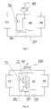
- a existing air-conditioning system includes a condenser 10, an evaporator 20, a capacity-variable and frequency-variable compressor 30, a throttling device 40, a four-way valve 60, a solenoid valve 70 and a one-way valve 50, wherein the capacity-variable and frequency-variable compressor 30 is switched by means of the motions of the one-way valve 50 and the solenoid valve 70.
- the solenoid valve 70 When the solenoid valve 70 is opened, a high-pressure coolant at an exhaust side flows to a suction port of a lower cylinder of the compressor, so that high pressure is formed at a suction end of the lower cylinder, and the capacity-variable and frequency-variable compressor 30 may operate with a single cylinder.
- the prior art has the disadvantages as follows.
- the disclosure mainly aims to provide an air-conditioning system and a method for controlling an air-conditioning system, which are intended to solve the problem in the prior art that switching easily fails in a process of switching a single-cylinder operation and a double-cylinder operation of a compressor of the air-conditioning system.
- an air-conditioning system which comprise a double-cylinder capacity-variable compressor, the double-cylinder capacity-variable compressor having a suction port of an upper cylinder, a suction port of a lower cylinder and an exhaust port.
- the air-conditioning system may further comprise a first solenoid valve.
- One end of the first solenoid valve may be connected to the exhaust port of the double-cylinder capacity-variable compressor, and the other end of the first solenoid valve may be connected to a one-way valve and the suction port of the lower cylinder of the double-cylinder capacity-variable compressor respectively.
- the air-conditioning system may further comprise a second solenoid valve, provided in a pipeline connecting the suction port of the lower cylinder of the double-cylinder capacity-variable compressor to an inlet of the gas-liquid separator.
- the air-conditioning system may further comprise a capillary pipe, connected in series to the second solenoid valve.
- the air-conditioning system may further comprise a temperature sensor, provided in a pipeline of the suction port of the lower cylinder.
- the air-conditioning system may further comprise a high-pressure sensor, provided in a pipeline of the exhaust port.
- a method for controlling an air-conditioning system which may be applied to the air-conditioning system.
- the control method comprise that: Step 10, when a double-cylinder capacity-variable compressor is under a single-cylinder operation state and is required to be switched to a double-cylinder operation state, a pipeline connecting a suction port of a lower cylinder of the double-cylinder capacity-variable compressor to an inlet of a gas-liquid separator is opened.
- the pipeline connecting the suction port of the lower cylinder of the double-cylinder capacity-variable compressor to the inlet of the gas-liquid separator is opened via a second solenoid valve, and a first solenoid valve may be closed after a period of time ts.
- control method further comprise that: Step 20, when the double-cylinder capacity-variable compressor has been under the single-cylinder operation state for over a period of time t1, a temperature T lower of the suction port of the lower cylinder of the double-cylinder capacity-variable compressor and a temperature T high of an exhaust port of the double-cylinder capacity-variable compressor are compared at a time interval of t2, and if T lower is smaller than or equal to T high , the second solenoid valve is closed after having been opened for a period of time t3.
- the time ts in the Step 10 may be relevant to an outdoor environment temperature TW.
- TW is greater than or equal to A°C
- ts may be equal to t5
- ts may be equal to t6
- ts may be equal to t7
- t5 when TW is greater than or equal to B°C and is smaller than A°C
- ts when TW is smaller than B°C, ts may be equal to t7, where t5, t6 and t7 may be pre-set time constants, and A and B may be pre-set temperature constants.
- Step 10 may further comprise that: the second solenoid valve is closed after the first solenoid valve has been closed for a period of time t4.
- a drain bypass pipeline provided with a solenoid valve is additionally provided between the suction port of the lower cylinder and the inlet of the gas-liquid separator, and a high-pressure coolant at a suction side of the lower cylinder is decompressed to the gas-liquid separator via the drain bypass pipeline, thereby optimizing the stability of the system when being switched from the single-cylinder operation to the double-cylinder operation.
- a drain bypass pipeline is additionally provided between a suction port of a lower cylinder of a double-cylinder capacity-variable compressor and an inlet of a gas-liquid separator.
- the drain bypass pipeline mainly comprises a capillary pipe and a second solenoid valve 72, a high-pressure sensor 100 is additionally provided at an exhaust side of the double-cylinder capacity-variable compressor to detect a condensation temperature T high , and a temperature sensor 90 is additionally provided at the suction port of the lower cylinder and serves as a detection tool for detecting a temperature T lower of the suction port of the lower cylinder.
- the second solenoid valve 72 of the drain bypass pipeline is opened so as to conduct decompression and drain motions.
- a liquid-state coolant on a connecting pipe between the lower cylinder of the double-cylinder capacity-variable compressor 30 and a first solenoid valve 71 can be discharged to the gas-liquid separator by means of automatic detection.
- a single-cylinder operation is switched to a double-cylinder operation, a high-pressure coolant at a suction side of the lower cylinder is decompressed to the gas-liquid separator via the drain bypass pipeline, so as to the single-cylinder operation is successfully switched to the double-cylinder operation, thereby improving the stability of the system when switched operation.
- an air-conditioning system comprises the double-cylinder capacity-variable compressor 30 and the gas-liquid separator.
- a suction port of an upper cylinder, the suction port of the lower cylinder and an exhaust port are led out of the double-cylinder capacity-variable compressor 30.
- the double-cylinder capacity-variable compressor 30, a first heat exchanger 10, a throttling assembly 40 and a second heat exchanger 20 are connected to form a loop.
- the air-conditioning system further comprises a four-way valve 60, the first solenoid valve 71 and a one-way valve 50.
- the first heat exchanger 10 and the second heat exchanger 20 are selectively connected to the double-cylinder capacity-variable compressor 30 via the four-way valve 60; one end of the first solenoid valve 71 is connected to the exhaust port of the double-cylinder capacity-variable compressor 30, and the other end of the first solenoid valve 71 is connected to the one-way valve 50 and the suction port of the lower cylinder respectively; one end of the one-way valve 50 is connected to a pipeline, the pipeline from the first solenoid valve 71 leading to the suction port of the lower cylinder, and the other end of the one-way valve 50 is communicated with an inner chamber of the gas-liquid separator; and the one-way valve 50 is allowed to flow from the gas-liquid separator to the suction port of the lower cylinder.
- a branch formed by the second solenoid valve 72 and the capillary pipe connected in series thereto is additionally provided and is connected between a pipeline of the suction port of the lower cylinder of the compressor and a pipeline of the inlet of the gas-liquid separator.
- the capillary pipe in a drain bypass loop has a function of controlling the drain flow. If a capillary pipe is too thick and too short, the flow will be over-high, the pressure reduction of the lower cylinder will be caused, and the single-cylinder operation cannot be continued in case of pressure shortage and will be switched to the double-cylinder operation. If a capillary pipe is too thin and too long, the flow will be over-low, a drain speed will be too low, and the drain motion cannot be completed within a set time. Thus, a moderate capillary pipe is needed for the drain bypass loop.
- a method for controlling an air-conditioning system comprises:
- a refrigerating/heating capacity adjustment range of the system is expanded by the combination of a double-cylinder or multi-cylinder frequency-variable compressor with the gas-liquid separator and a capacity variation technology.
- the bypass branch formed by the second solenoid valve and the capillary pipe has main functions as follows. When it is necessary to close the first solenoid valve, the second solenoid valve is opened to reduce the pressure of the pipeline between the suction port of the lower cylinder and the first solenoid valve to be consistent with low pressure so as to ensure that the compressor is quickly switched to be under double-cylinder operation after the first solenoid valve is closed.
- the unit When the unit is under the single-cylinder operation, it can be judged whether liquid is collected at the suction port of the lower cylinder by means of temperature detected by a pipeline temperature sensor at the suction port of the lower cylinder of the compressor and high-pressure temperature detected by a high-pressure sensor.
- the second solenoid valve When the liquid collection is judged, the second solenoid valve is opened for a period of time, so that the effect of preventing a liquid impact when the compressor is switched from the single-cylinder operation to the double-cylinder operation after the single-cylinder operation lasts long.
Landscapes
- Engineering & Computer Science (AREA)
- Physics & Mathematics (AREA)
- Mechanical Engineering (AREA)
- Thermal Sciences (AREA)
- General Engineering & Computer Science (AREA)
- Applications Or Details Of Rotary Compressors (AREA)
- Control Of Positive-Displacement Pumps (AREA)
- Air Conditioning Control Device (AREA)
Abstract
Description
- The disclosure relates to the field of air conditioners, and in particular to an air-conditioning system and a method for controlling an air-conditioning system.
- As shown in
Fig. 1 , a existing air-conditioning system includes acondenser 10, anevaporator 20, a capacity-variable and frequency-variable compressor 30, athrottling device 40, a four-way valve 60, asolenoid valve 70 and a one-way valve 50, wherein the capacity-variable and frequency-variable compressor 30 is switched by means of the motions of the one-way valve 50 and thesolenoid valve 70. When thesolenoid valve 70 is opened, a high-pressure coolant at an exhaust side flows to a suction port of a lower cylinder of the compressor, so that high pressure is formed at a suction end of the lower cylinder, and the capacity-variable and frequency-variable compressor 30 may operate with a single cylinder. When thesolenoid valve 70 is closed, a low-pressure coolant of a gas-liquid separator flows to the suction port of the lower cylinder, so that low pressure is formed at the suction port of the lower cylinder, and the capacity-variable and frequency-variable compressor is switched to operate with double cylinders. - The prior art has the disadvantages as follows.
- (1) When a single-cylinder operation is switched to a double-cylinder operation or a multi-cylinder operation, the solenoid valve is closed. However, since a connecting pipe from the suction port of the lower cylinder to the solenoid valve is still under a high-pressure state and the one-way valve is under a shut-off state due to the existence of a pressure difference, the low-pressure coolant of the gas-liquid separator cannot flow to a lower cylinder, thereby easily causing instability of the system during switching from the single-cylinder operation to the double-cylinder operation.
- (2) During the single-cylinder operation, the connecting pipe from the lower cylinder of the compressor to the solenoid valve is at a high-pressure side. However, since the coolant is under a stationary state, the temperature of the coolant drops along with heat exchange for an environment temperature, and the coolant is easily condensed to a liquid state when the temperature drop lasts long. At this time, if the single-cylinder operation is switched to the double-cylinder operation, the liquid-state coolant will flow to the lower cylinder, so that a liquid impact is triggered for the lower cylinder, and therefore the compressor is damaged.
- (3) In order to solve the problem in (1), if a capillary pipe is additionally provided at the connecting pipe of the suction port of the lower cylinder and the solenoid valve and is connected to an inlet of the gas-liquid separator, when the single-cylinder operation is switched to the double-cylinder operation, the high-pressure coolant at the suction port of the lower cylinder is decompressed to the inlet of the gas-liquid separator via the capillary pipe, the low-pressure coolant is formed at the suction port of the lower cylinder, and switching easily succeeds. However, since the capillary pipe flows for a long time, circulating coolants will be reduced accordingly so as to cause a heat loss.
- The disclosure mainly aims to provide an air-conditioning system and a method for controlling an air-conditioning system, which are intended to solve the problem in the prior art that switching easily fails in a process of switching a single-cylinder operation and a double-cylinder operation of a compressor of the air-conditioning system.
- In order to achieve the aim, according to an aspect of the disclosure, an air-conditioning system is provided, which comprise a double-cylinder capacity-variable compressor, the double-cylinder capacity-variable compressor having a suction port of an upper cylinder, a suction port of a lower cylinder and an exhaust port. The air-conditioning system may further comprise a first solenoid valve. One end of the first solenoid valve may be connected to the exhaust port of the double-cylinder capacity-variable compressor, and the other end of the first solenoid valve may be connected to a one-way valve and the suction port of the lower cylinder of the double-cylinder capacity-variable compressor respectively. One end of the one-way valve may be connected to the first solenoid valve, and the other end of the one-way valve may be communicated with an inner chamber of a gas-liquid separator. The air-conditioning system may further comprise a second solenoid valve, provided in a pipeline connecting the suction port of the lower cylinder of the double-cylinder capacity-variable compressor to an inlet of the gas-liquid separator.
- Furthermore, the air-conditioning system may further comprise a capillary pipe, connected in series to the second solenoid valve.
- Furthermore, the air-conditioning system may further comprise a temperature sensor, provided in a pipeline of the suction port of the lower cylinder.
- Furthermore, the air-conditioning system may further comprise a high-pressure sensor, provided in a pipeline of the exhaust port.
- According to another aspect of the disclosure, a method for controlling an air-conditioning system is provided, which may be applied to the air-conditioning system. The control method comprise that:
Step 10, when a double-cylinder capacity-variable compressor is under a single-cylinder operation state and is required to be switched to a double-cylinder operation state, a pipeline connecting a suction port of a lower cylinder of the double-cylinder capacity-variable compressor to an inlet of a gas-liquid separator is opened. - Furthermore, in the
Step 10, the pipeline connecting the suction port of the lower cylinder of the double-cylinder capacity-variable compressor to the inlet of the gas-liquid separator is opened via a second solenoid valve, and a first solenoid valve may be closed after a period of time ts. - Furthermore, the control method further comprise that:
Step 20, when the double-cylinder capacity-variable compressor has been under the single-cylinder operation state for over a period of time t1, a temperature Tlower of the suction port of the lower cylinder of the double-cylinder capacity-variable compressor and a temperature Thigh of an exhaust port of the double-cylinder capacity-variable compressor are compared at a time interval of t2, and if Tlower is smaller than or equal to Thigh, the second solenoid valve is closed after having been opened for a period of time t3. - Furthermore, the time ts in the
Step 10 may be relevant to an outdoor environment temperature TW. When TW is greater than or equal to A°C, ts may be equal to t5, when TW is greater than or equal to B°C and is smaller than A°C, ts may be equal to t6, and when TW is smaller than B°C, ts may be equal to t7, where t5, t6 and t7 may be pre-set time constants, and A and B may be pre-set temperature constants. - Furthermore, the
Step 10 may further comprise that: the second solenoid valve is closed after the first solenoid valve has been closed for a period of time t4. - By means of the technical solutions, a drain bypass pipeline provided with a solenoid valve is additionally provided between the suction port of the lower cylinder and the inlet of the gas-liquid separator, and a high-pressure coolant at a suction side of the lower cylinder is decompressed to the gas-liquid separator via the drain bypass pipeline, thereby optimizing the stability of the system when being switched from the single-cylinder operation to the double-cylinder operation.
- The specification drawings forming a part of the disclosure are intended to provide further understanding of the disclosure. The schematic embodiments and descriptions of the disclosure are intended to explain the disclosure, and do not form improper limits to the disclosure. In the drawings:
-
Fig. 1 shows an air-conditioning system with a capacity-variable and frequency-variable compressor in the prior art; -
Fig. 2 shows an air-conditioning system according to the disclosure; and -
Fig. 3 shows a flowchart of a control method of th air-conditioning system according to the disclosure. - It is important to note that the embodiments of the disclosure and the characteristics in the embodiments can be combined under the condition of no conflicts. The disclosure is described below with reference to the drawings and the embodiments in detail.
- As shown in
Fig. 2 , according to the disclosure, on the basis of the prior art, a drain bypass pipeline is additionally provided between a suction port of a lower cylinder of a double-cylinder capacity-variable compressor and an inlet of a gas-liquid separator. The drain bypass pipeline mainly comprises a capillary pipe and asecond solenoid valve 72, a high-pressure sensor 100 is additionally provided at an exhaust side of the double-cylinder capacity-variable compressor to detect a condensation temperature Thigh, and atemperature sensor 90 is additionally provided at the suction port of the lower cylinder and serves as a detection tool for detecting a temperature Tlower of the suction port of the lower cylinder. Under a specific condition, thesecond solenoid valve 72 of the drain bypass pipeline is opened so as to conduct decompression and drain motions. When the suction port of the lower cylinder is under a liquid collection state, a liquid-state coolant on a connecting pipe between the lower cylinder of the double-cylinder capacity-variable compressor 30 and afirst solenoid valve 71 can be discharged to the gas-liquid separator by means of automatic detection. When a single-cylinder operation is switched to a double-cylinder operation, a high-pressure coolant at a suction side of the lower cylinder is decompressed to the gas-liquid separator via the drain bypass pipeline, so as to the single-cylinder operation is successfully switched to the double-cylinder operation, thereby improving the stability of the system when switched operation. - As shown in
Fig. 2 , an air-conditioning system according to the disclosure comprises the double-cylinder capacity-variable compressor 30 and the gas-liquid separator. A suction port of an upper cylinder, the suction port of the lower cylinder and an exhaust port are led out of the double-cylinder capacity-variable compressor 30. The double-cylinder capacity-variable compressor 30, afirst heat exchanger 10, athrottling assembly 40 and asecond heat exchanger 20 are connected to form a loop. The air-conditioning system further comprises a four-way valve 60, thefirst solenoid valve 71 and a one-way valve 50. Thefirst heat exchanger 10 and thesecond heat exchanger 20 are selectively connected to the double-cylinder capacity-variable compressor 30 via the four-way valve 60; one end of thefirst solenoid valve 71 is connected to the exhaust port of the double-cylinder capacity-variable compressor 30, and the other end of thefirst solenoid valve 71 is connected to the one-way valve 50 and the suction port of the lower cylinder respectively; one end of the one-way valve 50 is connected to a pipeline, the pipeline from thefirst solenoid valve 71 leading to the suction port of the lower cylinder, and the other end of the one-way valve 50 is communicated with an inner chamber of the gas-liquid separator; and the one-way valve 50 is allowed to flow from the gas-liquid separator to the suction port of the lower cylinder. In the disclosure, a branch formed by thesecond solenoid valve 72 and the capillary pipe connected in series thereto is additionally provided and is connected between a pipeline of the suction port of the lower cylinder of the compressor and a pipeline of the inlet of the gas-liquid separator. - The capillary pipe in a drain bypass loop has a function of controlling the drain flow. If a capillary pipe is too thick and too short, the flow will be over-high, the pressure reduction of the lower cylinder will be caused, and the single-cylinder operation cannot be continued in case of pressure shortage and will be switched to the double-cylinder operation. If a capillary pipe is too thin and too long, the flow will be over-low, a drain speed will be too low, and the drain motion cannot be completed within a set time. Thus, a moderate capillary pipe is needed for the drain bypass loop.
- As shown in
Fig. 3 , a method for controlling an air-conditioning system according to the disclosure comprises: - (1) When a double-cylinder capacity-
variable compressor 30 is under single-cylinder operation and the single-cylinder operation time of the double-cylinder capacity-variable compressor 30 exceeds a period of time t1, Tlower and Thigh are compared at a time interval of t2, and if Tlower is smaller than or equal to Thigh, it is judged that liquid is collected on a pipeline of the suction port of the lower cylinder of a unit, and asecond solenoid valve 72 is closed after having been opened for a period of time t3 so as to achieve an interval drain effect. - (2) When the double-cylinder capacity-
variable compressor 30 is under the single-cylinder operation and is required to be switched to double-cylinder operation, afirst solenoid valve 71 is closed after thesecond solenoid valve 72 has been opened for a period of time ts, and thesecond solenoid valve 72 is closed after thefirst solenoid valve 71 has been closed for a period of time t4 so as to achieve a decompression effect. - (3) Since the liquid collection situations of different outdoor environment temperatures TW are different, the time ts in Step (2) is relevant to the outdoor environment temperatures. For example, (A and B are pre-set temperature constants which can be determined via experiments)
- a) when TW is greater than or equal to A°C, ts is equal to t5;
- b) when TW is greater than or equal to B°C and is smaller than A°C, ts is equal to t6; and
- c) when TW is smaller than B°C, ts is equal to t7. (where t1, t2, t3, t4, t5, t6 and t7 are pre-set time which can be determined via experiments.)
- In the disclosure, a refrigerating/heating capacity adjustment range of the system is expanded by the combination of a double-cylinder or multi-cylinder frequency-variable compressor with the gas-liquid separator and a capacity variation technology. The bypass branch formed by the second solenoid valve and the capillary pipe has main functions as follows. When it is necessary to close the first solenoid valve, the second solenoid valve is opened to reduce the pressure of the pipeline between the suction port of the lower cylinder and the first solenoid valve to be consistent with low pressure so as to ensure that the compressor is quickly switched to be under double-cylinder operation after the first solenoid valve is closed. When the unit is under the single-cylinder operation, it can be judged whether liquid is collected at the suction port of the lower cylinder by means of temperature detected by a pipeline temperature sensor at the suction port of the lower cylinder of the compressor and high-pressure temperature detected by a high-pressure sensor. When the liquid collection is judged, the second solenoid valve is opened for a period of time, so that the effect of preventing a liquid impact when the compressor is switched from the single-cylinder operation to the double-cylinder operation after the single-cylinder operation lasts long.
- The above is only the preferred embodiments of the disclosure, and is not intended to limit the disclosure. There can be various modifications and variations in the disclosure for those skilled in the art. Any modifications, equivalent replacements, improvements and the like within the spirit and principle of the disclosure shall fall within the protection scope of the disclosure.
Claims (9)
- An air-conditioning system, comprising a double-cylinder capacity-variable compressor (30), the double-cylinder capacity-variable compressor (30) having a suction port of an upper cylinder, a suction port of a lower cylinder and an exhaust port, and the air-conditioning system further comprising a first solenoid valve (71), one end of the first solenoid valve (71) is connected to the exhaust port of the double-cylinder capacity-variable compressor (30), and the other end of the first solenoid valve (71) is connected to a one-way valve (50) and the suction port of the lower cylinder of the double-cylinder capacity-variable compressor (30) respectively; one end of the one-way valve (50) is connected to the first solenoid valve (71), and the other end of the one-way valve (50) is communicated with an inner chamber of a gas-liquid separator; wherein
the air-conditioning system further comprises a second solenoid valve (72), provided in a pipeline connecting the suction port of the lower cylinder of the double-cylinder capacity-variable compressor (30) to an inlet of the gas-liquid separator. - The air-conditioning system according to claim 1, wherein further comprising a capillary pipe, connected in series to the second solenoid valve (72).
- The air-conditioning system according to claim 1, wherein further comprising a temperature sensor (90), provided in a pipeline of the suction port of the lower cylinder.
- The air-conditioning system according to claim 1, wherein further comprising a high-pressure sensor (100), provided in a pipeline of the exhaust port.
- A method for controlling an air-conditioning system, wherein applied to an air-conditioning system according to any one of claims 1 to 4, the control method comprising: Step 10, when a double-cylinder capacity-variable compressor (30) is under a single-cylinder operation state and is required to be switched to a double-cylinder operation state, opening a pipeline connecting a suction port of a lower cylinder of the double-cylinder capacity-variable compressor (30) to an inlet of a gas-liquid separator.
- The method for controlling an air-conditioning system according to claim 5, wherein in the Step 10, the pipeline connecting the suction port of the lower cylinder of the double-cylinder capacity-variable compressor (30) to the inlet of the gas-liquid separator is opened via a second solenoid valve (72), and a first solenoid valve (71) is closed after a period of time ts.
- The method for controlling an air-conditioning system according to claim 6, wherein the control method further comprising: Step 20, when the double-cylinder capacity-variable compressor (30) has been under the single-cylinder operation state for over a period of time t1, comparing a temperature Tlower of the suction port of the lower cylinder of the double-cylinder capacity-variable compressor (30) with a temperature Thigh of an exhaust port of the double-cylinder capacity-variable compressor (30) at a time interval of t2, and if Tlower is smaller than or equal to Thigh, closing the second solenoid valve (72) after having been opened for a period of time t3.
- The method for controlling an air-conditioning system according to claim 6, wherein the time ts in the Step 10 is relevant to an outdoor environment temperature TW; and when TW is greater than or equal to A°C, ts is equal to t5, when TW is greater than or equal to B°C and is smaller than A°C, ts is equal to t6, and when TW is smaller than B°C, ts is equal to t7, wherein t5, t6 and t7 are pre-set time constants, and A and B are pre-set temperature constants.
- The method for controlling an air-conditioning system according to claim 6, wherein the Step 10 further comprises: closing the second solenoid valve (72) after the first solenoid valve (71) has been closed for a period of time t4.
Applications Claiming Priority (2)
| Application Number | Priority Date | Filing Date | Title |
|---|---|---|---|
| CN201310728551.5A CN104729130B (en) | 2013-12-24 | 2013-12-24 | Air conditioning system and control method thereof |
| PCT/CN2014/088670 WO2015096539A1 (en) | 2013-12-24 | 2014-10-15 | Air-conditioning system and method for controlling same |
Publications (3)
| Publication Number | Publication Date |
|---|---|
| EP3091311A1 true EP3091311A1 (en) | 2016-11-09 |
| EP3091311A4 EP3091311A4 (en) | 2017-09-20 |
| EP3091311B1 EP3091311B1 (en) | 2019-02-27 |
Family
ID=53453275
Family Applications (1)
| Application Number | Title | Priority Date | Filing Date |
|---|---|---|---|
| EP14875380.9A Active EP3091311B1 (en) | 2013-12-24 | 2014-10-15 | Air-conditioning system and method for controlling air-conditioning system |
Country Status (6)
| Country | Link |
|---|---|
| EP (1) | EP3091311B1 (en) |
| JP (1) | JP6498677B2 (en) |
| CN (1) | CN104729130B (en) |
| ES (1) | ES2717515T3 (en) |
| TR (1) | TR201905512T4 (en) |
| WO (1) | WO2015096539A1 (en) |
Cited By (3)
| Publication number | Priority date | Publication date | Assignee | Title |
|---|---|---|---|---|
| WO2018179014A1 (en) * | 2017-03-28 | 2018-10-04 | Evolving Living Innovation Center E.L.I.C. S.r.l. | Heat pump apparatus for changing air within domestic spaces and respective mode of operation |
| WO2019000869A1 (en) * | 2017-06-30 | 2019-01-03 | 广东美的制冷设备有限公司 | Air conditioning system and air conditioning system control method |
| WO2019000868A1 (en) * | 2017-06-30 | 2019-01-03 | 广东美的制冷设备有限公司 | Air conditioning system and control method for air conditioning system |
Families Citing this family (17)
| Publication number | Priority date | Publication date | Assignee | Title |
|---|---|---|---|---|
| CN105485991B (en) * | 2016-01-04 | 2018-07-24 | 珠海格力电器股份有限公司 | Variable-capacity compressor system, control method and air conditioner |
| CN105650925B (en) * | 2016-01-14 | 2018-03-30 | 安徽美芝精密制造有限公司 | refrigeration system and its control method |
| ITUB20160682A1 (en) * | 2016-03-01 | 2017-09-01 | Evolving Living Innovation Center Elic S R L | HEAT PUMP EQUIPMENT FOR REPLACEMENT OF AIR IN HOME PREMISES AND ITS OPERATING METHOD |
| CN105627615B (en) * | 2016-03-03 | 2018-11-27 | 广东美的制冷设备有限公司 | The control method of air-conditioning system and air-conditioning system |
| CN105698456B (en) * | 2016-03-21 | 2018-02-13 | 珠海格力电器股份有限公司 | Variable capacity compressor system control method |
| CN106152342B (en) * | 2016-07-04 | 2020-12-04 | 珠海格力电器股份有限公司 | Variable-displacement-ratio two-stage compression air conditioning system and control method thereof |
| CN106595138A (en) * | 2016-10-17 | 2017-04-26 | 珠海格力电器股份有限公司 | Air conditioning system and method for reducing liquid storage of gas-liquid separator |
| CN106403373A (en) * | 2016-10-19 | 2017-02-15 | 珠海格力电器股份有限公司 | Heat pump system, control method and refrigerating unit |
| CN106440443B (en) * | 2016-11-25 | 2022-04-12 | 广州华凌制冷设备有限公司 | Air conditioning system suitable for high-temperature refrigeration and control method |
| CN107014038B (en) * | 2017-04-13 | 2020-12-29 | 青岛海尔空调器有限总公司 | Air conditioner and control method |
| CN107388650B (en) * | 2017-07-26 | 2019-07-26 | 珠海格力电器股份有限公司 | Air conditioning system and method for controlling liquid accumulation in gas-liquid separator |
| CN108131859B (en) * | 2017-12-25 | 2023-08-29 | 珠海格力电器股份有限公司 | Air conditioning system of variable capacity compressor, control method of air conditioning system, storage medium and processor |
| CN108317787A (en) * | 2017-12-25 | 2018-07-24 | 珠海格力电器股份有限公司 | Air conditioning system of compressor, control method of air conditioning system, storage medium and processor |
| CN108981233A (en) * | 2018-07-25 | 2018-12-11 | 珠海格力电器股份有限公司 | Variable-capacity compression assembly and variable-capacity air conditioning system |
| CN110319008A (en) * | 2019-08-08 | 2019-10-11 | 珠海格力电器股份有限公司 | Compressor with two-stage exhaust function and air conditioning system |
| CN111594443B (en) * | 2020-05-12 | 2024-05-14 | 珠海凌达压缩机有限公司 | Compressor assembly, air conditioning system comprising same and control method |
| CN116241962B (en) * | 2023-03-29 | 2026-02-10 | 珠海格力电器股份有限公司 | Air conditioning systems, air conditioning units and control methods |
Family Cites Families (14)
| Publication number | Priority date | Publication date | Assignee | Title |
|---|---|---|---|---|
| JPH07103856B2 (en) * | 1986-09-30 | 1995-11-08 | 三菱電機株式会社 | Multi-cylinder rotary compressor |
| JP4447859B2 (en) * | 2003-06-20 | 2010-04-07 | 東芝キヤリア株式会社 | Rotary hermetic compressor and refrigeration cycle apparatus |
| JP4247077B2 (en) * | 2003-09-02 | 2009-04-02 | 東芝キヤリア株式会社 | Air conditioner |
| JP2005344683A (en) * | 2004-06-07 | 2005-12-15 | Toshiba Kyaria Kk | Hermetic compressor |
| JP2006022723A (en) * | 2004-07-08 | 2006-01-26 | Sanyo Electric Co Ltd | Compression system and refrigerating apparatus using the same |
| KR100961301B1 (en) * | 2005-08-25 | 2010-06-04 | 도시바 캐리어 가부시키가이샤 | Hermetic compressors and refrigeration cycle units |
| KR20070074300A (en) * | 2006-01-09 | 2007-07-12 | 삼성전자주식회사 | Rotary compressor |
| JP2008057395A (en) * | 2006-08-30 | 2008-03-13 | Toshiba Kyaria Kk | Hermetic rotary compressor and refrigeration cycle apparatus |
| KR101409876B1 (en) * | 2008-08-22 | 2014-06-20 | 엘지전자 주식회사 | Variable capacity type rotary compressor and refrigerator having the same and method for driving thereof |
| CN201772685U (en) * | 2010-05-24 | 2011-03-23 | 上海日立电器有限公司 | Two-stage rotary compressor and heat pump circulation system with variable capacity defrosting |
| CN202303713U (en) * | 2011-09-15 | 2012-07-04 | 宁波奥克斯空调有限公司 | Double-cylinder variable-displacement heat pump air conditioner system |
| JP2013076377A (en) * | 2011-09-30 | 2013-04-25 | Toshiba Corp | Control device of hermetic compressor |
| CN203687474U (en) * | 2013-12-24 | 2014-07-02 | 珠海格力电器股份有限公司 | Air conditioning system |
| CN104061723B (en) * | 2014-06-09 | 2016-05-04 | 珠海格力电器股份有限公司 | Air conditioning system |
-
2013
- 2013-12-24 CN CN201310728551.5A patent/CN104729130B/en active Active
-
2014
- 2014-10-15 WO PCT/CN2014/088670 patent/WO2015096539A1/en not_active Ceased
- 2014-10-15 EP EP14875380.9A patent/EP3091311B1/en active Active
- 2014-10-15 JP JP2016542927A patent/JP6498677B2/en active Active
- 2014-10-15 ES ES14875380T patent/ES2717515T3/en active Active
- 2014-10-15 TR TR2019/05512T patent/TR201905512T4/en unknown
Cited By (3)
| Publication number | Priority date | Publication date | Assignee | Title |
|---|---|---|---|---|
| WO2018179014A1 (en) * | 2017-03-28 | 2018-10-04 | Evolving Living Innovation Center E.L.I.C. S.r.l. | Heat pump apparatus for changing air within domestic spaces and respective mode of operation |
| WO2019000869A1 (en) * | 2017-06-30 | 2019-01-03 | 广东美的制冷设备有限公司 | Air conditioning system and air conditioning system control method |
| WO2019000868A1 (en) * | 2017-06-30 | 2019-01-03 | 广东美的制冷设备有限公司 | Air conditioning system and control method for air conditioning system |
Also Published As
| Publication number | Publication date |
|---|---|
| JP6498677B2 (en) | 2019-04-10 |
| CN104729130B (en) | 2017-05-10 |
| EP3091311A4 (en) | 2017-09-20 |
| TR201905512T4 (en) | 2019-05-21 |
| ES2717515T3 (en) | 2019-06-21 |
| JP2017502247A (en) | 2017-01-19 |
| EP3091311B1 (en) | 2019-02-27 |
| WO2015096539A1 (en) | 2015-07-02 |
| CN104729130A (en) | 2015-06-24 |
Similar Documents
| Publication | Publication Date | Title |
|---|---|---|
| EP3091311B1 (en) | Air-conditioning system and method for controlling air-conditioning system | |
| US8307668B2 (en) | Air conditioner | |
| EP1826513A1 (en) | Refrigerating air conditioner | |
| CN104896672B (en) | Defrosting control method of air conditioner and air conditioner | |
| KR20150070894A (en) | Control method for air conditioner | |
| WO2015122056A1 (en) | Air conditioning device | |
| CN104792075A (en) | Three-tube multi-split air-conditioning system oil return or defrosting control method and system thereof | |
| EP3101372B1 (en) | Freezing unit | |
| CN108662799A (en) | Multi-stage refrigeration system and its control method | |
| CN106918120A (en) | Air-conditioner anti-condensation control system, air-conditioner and condensation prevention control method | |
| KR101635703B1 (en) | A refrigerant recovery apparatus and a method for controlling the same | |
| CN107843023A (en) | A kind of refrigerating machine device | |
| CN107314584B (en) | Air-conditioning system and liquid accumulation control method of gas-liquid separator | |
| CN107388650A (en) | Air conditioning system and gas-liquid separator accumulated liquid control method | |
| KR102487917B1 (en) | Air conditioner including heat storage tank and a method controlling the same | |
| JP2000304373A (en) | Engine heat pump | |
| EP3734192B1 (en) | Air conditioner system | |
| KR101504003B1 (en) | Heat pump type air conditioner | |
| JP2020165545A (en) | Air conditioner | |
| KR20090089953A (en) | Air conditioner and control method thereof | |
| CN106440453B (en) | Split type air source heating system and control method thereof | |
| KR20140094343A (en) | An air conditioner and a control method the same | |
| JP6404539B2 (en) | Air conditioner | |
| CN203687474U (en) | Air conditioning system | |
| KR102032183B1 (en) | An air conditioner and a control method the same |
Legal Events
| Date | Code | Title | Description |
|---|---|---|---|
| PUAI | Public reference made under article 153(3) epc to a published international application that has entered the european phase |
Free format text: ORIGINAL CODE: 0009012 |
|
| 17P | Request for examination filed |
Effective date: 20160628 |
|
| AK | Designated contracting states |
Kind code of ref document: A1 Designated state(s): AL AT BE BG CH CY CZ DE DK EE ES FI FR GB GR HR HU IE IS IT LI LT LU LV MC MK MT NL NO PL PT RO RS SE SI SK SM TR |
|
| AX | Request for extension of the european patent |
Extension state: BA ME |
|
| DAX | Request for extension of the european patent (deleted) | ||
| A4 | Supplementary search report drawn up and despatched |
Effective date: 20170821 |
|
| RIC1 | Information provided on ipc code assigned before grant |
Ipc: F04C 23/00 20060101ALI20170814BHEP Ipc: F25B 41/04 20060101ALI20170814BHEP Ipc: F25B 13/00 20060101AFI20170814BHEP |
|
| GRAP | Despatch of communication of intention to grant a patent |
Free format text: ORIGINAL CODE: EPIDOSNIGR1 |
|
| STAA | Information on the status of an ep patent application or granted ep patent |
Free format text: STATUS: GRANT OF PATENT IS INTENDED |
|
| INTG | Intention to grant announced |
Effective date: 20180813 |
|
| GRAS | Grant fee paid |
Free format text: ORIGINAL CODE: EPIDOSNIGR3 |
|
| GRAA | (expected) grant |
Free format text: ORIGINAL CODE: 0009210 |
|
| STAA | Information on the status of an ep patent application or granted ep patent |
Free format text: STATUS: THE PATENT HAS BEEN GRANTED |
|
| AK | Designated contracting states |
Kind code of ref document: B1 Designated state(s): AL AT BE BG CH CY CZ DE DK EE ES FI FR GB GR HR HU IE IS IT LI LT LU LV MC MK MT NL NO PL PT RO RS SE SI SK SM TR |
|
| REG | Reference to a national code |
Ref country code: GB Ref legal event code: FG4D |
|
| REG | Reference to a national code |
Ref country code: CH Ref legal event code: EP |
|
| REG | Reference to a national code |
Ref country code: AT Ref legal event code: REF Ref document number: 1101945 Country of ref document: AT Kind code of ref document: T Effective date: 20190315 |
|
| REG | Reference to a national code |
Ref country code: IE Ref legal event code: FG4D |
|
| REG | Reference to a national code |
Ref country code: DE Ref legal event code: R096 Ref document number: 602014042106 Country of ref document: DE |
|
| REG | Reference to a national code |
Ref country code: ES Ref legal event code: FG2A Ref document number: 2717515 Country of ref document: ES Kind code of ref document: T3 Effective date: 20190621 |
|
| REG | Reference to a national code |
Ref country code: NL Ref legal event code: MP Effective date: 20190227 |
|
| REG | Reference to a national code |
Ref country code: LT Ref legal event code: MG4D |
|
| PG25 | Lapsed in a contracting state [announced via postgrant information from national office to epo] |
Ref country code: PT Free format text: LAPSE BECAUSE OF FAILURE TO SUBMIT A TRANSLATION OF THE DESCRIPTION OR TO PAY THE FEE WITHIN THE PRESCRIBED TIME-LIMIT Effective date: 20190627 Ref country code: NL Free format text: LAPSE BECAUSE OF FAILURE TO SUBMIT A TRANSLATION OF THE DESCRIPTION OR TO PAY THE FEE WITHIN THE PRESCRIBED TIME-LIMIT Effective date: 20190227 Ref country code: LT Free format text: LAPSE BECAUSE OF FAILURE TO SUBMIT A TRANSLATION OF THE DESCRIPTION OR TO PAY THE FEE WITHIN THE PRESCRIBED TIME-LIMIT Effective date: 20190227 Ref country code: NO Free format text: LAPSE BECAUSE OF FAILURE TO SUBMIT A TRANSLATION OF THE DESCRIPTION OR TO PAY THE FEE WITHIN THE PRESCRIBED TIME-LIMIT Effective date: 20190527 Ref country code: SE Free format text: LAPSE BECAUSE OF FAILURE TO SUBMIT A TRANSLATION OF THE DESCRIPTION OR TO PAY THE FEE WITHIN THE PRESCRIBED TIME-LIMIT Effective date: 20190227 Ref country code: FI Free format text: LAPSE BECAUSE OF FAILURE TO SUBMIT A TRANSLATION OF THE DESCRIPTION OR TO PAY THE FEE WITHIN THE PRESCRIBED TIME-LIMIT Effective date: 20190227 |
|
| REG | Reference to a national code |
Ref country code: GR Ref legal event code: EP Ref document number: 20190401107 Country of ref document: GR Effective date: 20190620 |
|
| PG25 | Lapsed in a contracting state [announced via postgrant information from national office to epo] |
Ref country code: BG Free format text: LAPSE BECAUSE OF FAILURE TO SUBMIT A TRANSLATION OF THE DESCRIPTION OR TO PAY THE FEE WITHIN THE PRESCRIBED TIME-LIMIT Effective date: 20190527 Ref country code: RS Free format text: LAPSE BECAUSE OF FAILURE TO SUBMIT A TRANSLATION OF THE DESCRIPTION OR TO PAY THE FEE WITHIN THE PRESCRIBED TIME-LIMIT Effective date: 20190227 Ref country code: IS Free format text: LAPSE BECAUSE OF FAILURE TO SUBMIT A TRANSLATION OF THE DESCRIPTION OR TO PAY THE FEE WITHIN THE PRESCRIBED TIME-LIMIT Effective date: 20190627 Ref country code: LV Free format text: LAPSE BECAUSE OF FAILURE TO SUBMIT A TRANSLATION OF THE DESCRIPTION OR TO PAY THE FEE WITHIN THE PRESCRIBED TIME-LIMIT Effective date: 20190227 Ref country code: HR Free format text: LAPSE BECAUSE OF FAILURE TO SUBMIT A TRANSLATION OF THE DESCRIPTION OR TO PAY THE FEE WITHIN THE PRESCRIBED TIME-LIMIT Effective date: 20190227 |
|
| REG | Reference to a national code |
Ref country code: AT Ref legal event code: MK05 Ref document number: 1101945 Country of ref document: AT Kind code of ref document: T Effective date: 20190227 |
|
| PG25 | Lapsed in a contracting state [announced via postgrant information from national office to epo] |
Ref country code: RO Free format text: LAPSE BECAUSE OF FAILURE TO SUBMIT A TRANSLATION OF THE DESCRIPTION OR TO PAY THE FEE WITHIN THE PRESCRIBED TIME-LIMIT Effective date: 20190227 Ref country code: SK Free format text: LAPSE BECAUSE OF FAILURE TO SUBMIT A TRANSLATION OF THE DESCRIPTION OR TO PAY THE FEE WITHIN THE PRESCRIBED TIME-LIMIT Effective date: 20190227 Ref country code: CZ Free format text: LAPSE BECAUSE OF FAILURE TO SUBMIT A TRANSLATION OF THE DESCRIPTION OR TO PAY THE FEE WITHIN THE PRESCRIBED TIME-LIMIT Effective date: 20190227 Ref country code: AL Free format text: LAPSE BECAUSE OF FAILURE TO SUBMIT A TRANSLATION OF THE DESCRIPTION OR TO PAY THE FEE WITHIN THE PRESCRIBED TIME-LIMIT Effective date: 20190227 Ref country code: DK Free format text: LAPSE BECAUSE OF FAILURE TO SUBMIT A TRANSLATION OF THE DESCRIPTION OR TO PAY THE FEE WITHIN THE PRESCRIBED TIME-LIMIT Effective date: 20190227 Ref country code: EE Free format text: LAPSE BECAUSE OF FAILURE TO SUBMIT A TRANSLATION OF THE DESCRIPTION OR TO PAY THE FEE WITHIN THE PRESCRIBED TIME-LIMIT Effective date: 20190227 |
|
| REG | Reference to a national code |
Ref country code: DE Ref legal event code: R097 Ref document number: 602014042106 Country of ref document: DE |
|
| PG25 | Lapsed in a contracting state [announced via postgrant information from national office to epo] |
Ref country code: SM Free format text: LAPSE BECAUSE OF FAILURE TO SUBMIT A TRANSLATION OF THE DESCRIPTION OR TO PAY THE FEE WITHIN THE PRESCRIBED TIME-LIMIT Effective date: 20190227 Ref country code: PL Free format text: LAPSE BECAUSE OF FAILURE TO SUBMIT A TRANSLATION OF THE DESCRIPTION OR TO PAY THE FEE WITHIN THE PRESCRIBED TIME-LIMIT Effective date: 20190227 |
|
| PG25 | Lapsed in a contracting state [announced via postgrant information from national office to epo] |
Ref country code: AT Free format text: LAPSE BECAUSE OF FAILURE TO SUBMIT A TRANSLATION OF THE DESCRIPTION OR TO PAY THE FEE WITHIN THE PRESCRIBED TIME-LIMIT Effective date: 20190227 |
|
| PLBE | No opposition filed within time limit |
Free format text: ORIGINAL CODE: 0009261 |
|
| STAA | Information on the status of an ep patent application or granted ep patent |
Free format text: STATUS: NO OPPOSITION FILED WITHIN TIME LIMIT |
|
| REG | Reference to a national code |
Ref country code: DE Ref legal event code: R082 Ref document number: 602014042106 Country of ref document: DE Representative=s name: STRAUS, ALEXANDER, DIPL.-CHEM.UNIV. DR.PHIL., DE Ref country code: DE Ref legal event code: R082 Ref document number: 602014042106 Country of ref document: DE Representative=s name: 2K PATENT- UND RECHTSANWAELTE PARTNERSCHAFT MB, DE |
|
| 26N | No opposition filed |
Effective date: 20191128 |
|
| PG25 | Lapsed in a contracting state [announced via postgrant information from national office to epo] |
Ref country code: SI Free format text: LAPSE BECAUSE OF FAILURE TO SUBMIT A TRANSLATION OF THE DESCRIPTION OR TO PAY THE FEE WITHIN THE PRESCRIBED TIME-LIMIT Effective date: 20190227 |
|
| PG25 | Lapsed in a contracting state [announced via postgrant information from national office to epo] |
Ref country code: MC Free format text: LAPSE BECAUSE OF FAILURE TO SUBMIT A TRANSLATION OF THE DESCRIPTION OR TO PAY THE FEE WITHIN THE PRESCRIBED TIME-LIMIT Effective date: 20190227 |
|
| REG | Reference to a national code |
Ref country code: CH Ref legal event code: PL |
|
| PG25 | Lapsed in a contracting state [announced via postgrant information from national office to epo] |
Ref country code: LI Free format text: LAPSE BECAUSE OF NON-PAYMENT OF DUE FEES Effective date: 20191031 Ref country code: LU Free format text: LAPSE BECAUSE OF NON-PAYMENT OF DUE FEES Effective date: 20191015 Ref country code: CH Free format text: LAPSE BECAUSE OF NON-PAYMENT OF DUE FEES Effective date: 20191031 |
|
| REG | Reference to a national code |
Ref country code: BE Ref legal event code: MM Effective date: 20191031 |
|
| PG25 | Lapsed in a contracting state [announced via postgrant information from national office to epo] |
Ref country code: BE Free format text: LAPSE BECAUSE OF NON-PAYMENT OF DUE FEES Effective date: 20191031 |
|
| PG25 | Lapsed in a contracting state [announced via postgrant information from national office to epo] |
Ref country code: IE Free format text: LAPSE BECAUSE OF NON-PAYMENT OF DUE FEES Effective date: 20191015 Ref country code: FR Free format text: LAPSE BECAUSE OF NON-PAYMENT OF DUE FEES Effective date: 20191031 |
|
| PG25 | Lapsed in a contracting state [announced via postgrant information from national office to epo] |
Ref country code: CY Free format text: LAPSE BECAUSE OF FAILURE TO SUBMIT A TRANSLATION OF THE DESCRIPTION OR TO PAY THE FEE WITHIN THE PRESCRIBED TIME-LIMIT Effective date: 20190227 |
|
| PG25 | Lapsed in a contracting state [announced via postgrant information from national office to epo] |
Ref country code: MT Free format text: LAPSE BECAUSE OF FAILURE TO SUBMIT A TRANSLATION OF THE DESCRIPTION OR TO PAY THE FEE WITHIN THE PRESCRIBED TIME-LIMIT Effective date: 20190227 Ref country code: HU Free format text: LAPSE BECAUSE OF FAILURE TO SUBMIT A TRANSLATION OF THE DESCRIPTION OR TO PAY THE FEE WITHIN THE PRESCRIBED TIME-LIMIT; INVALID AB INITIO Effective date: 20141015 |
|
| PG25 | Lapsed in a contracting state [announced via postgrant information from national office to epo] |
Ref country code: MK Free format text: LAPSE BECAUSE OF FAILURE TO SUBMIT A TRANSLATION OF THE DESCRIPTION OR TO PAY THE FEE WITHIN THE PRESCRIBED TIME-LIMIT Effective date: 20190227 |
|
| P01 | Opt-out of the competence of the unified patent court (upc) registered |
Effective date: 20230530 |
|
| REG | Reference to a national code |
Ref country code: DE Ref legal event code: R082 Ref document number: 602014042106 Country of ref document: DE Representative=s name: STRAUS, ALEXANDER, DIPL.-CHEM.UNIV. DR.PHIL., DE |
|
| PGFP | Annual fee paid to national office [announced via postgrant information from national office to epo] |
Ref country code: TR Payment date: 20250908 Year of fee payment: 12 |
|
| PGFP | Annual fee paid to national office [announced via postgrant information from national office to epo] |
Ref country code: GB Payment date: 20250908 Year of fee payment: 12 |
|
| PGFP | Annual fee paid to national office [announced via postgrant information from national office to epo] |
Ref country code: DE Payment date: 20251020 Year of fee payment: 12 |
|
| PGFP | Annual fee paid to national office [announced via postgrant information from national office to epo] |
Ref country code: IT Payment date: 20251031 Year of fee payment: 12 |
|
| PGFP | Annual fee paid to national office [announced via postgrant information from national office to epo] |
Ref country code: GR Payment date: 20251021 Year of fee payment: 12 |
|
| PGFP | Annual fee paid to national office [announced via postgrant information from national office to epo] |
Ref country code: ES Payment date: 20251114 Year of fee payment: 12 |