EP3091236B1 - Fan and mounting bracket for an air mover - Google Patents
Fan and mounting bracket for an air mover Download PDFInfo
- Publication number
- EP3091236B1 EP3091236B1 EP16157715.0A EP16157715A EP3091236B1 EP 3091236 B1 EP3091236 B1 EP 3091236B1 EP 16157715 A EP16157715 A EP 16157715A EP 3091236 B1 EP3091236 B1 EP 3091236B1
- Authority
- EP
- European Patent Office
- Prior art keywords
- impeller
- housing
- inlet
- mounting bracket
- chords
- Prior art date
- Legal status (The legal status is an assumption and is not a legal conclusion. Google has not performed a legal analysis and makes no representation as to the accuracy of the status listed.)
- Not-in-force
Links
Images


Classifications
-
- F—MECHANICAL ENGINEERING; LIGHTING; HEATING; WEAPONS; BLASTING
- F04—POSITIVE - DISPLACEMENT MACHINES FOR LIQUIDS; PUMPS FOR LIQUIDS OR ELASTIC FLUIDS
- F04D—NON-POSITIVE-DISPLACEMENT PUMPS
- F04D29/00—Details, component parts, or accessories
- F04D29/40—Casings; Connections of working fluid
- F04D29/52—Casings; Connections of working fluid for axial pumps
- F04D29/522—Casings; Connections of working fluid for axial pumps especially adapted for elastic fluid pumps
-
- F—MECHANICAL ENGINEERING; LIGHTING; HEATING; WEAPONS; BLASTING
- F04—POSITIVE - DISPLACEMENT MACHINES FOR LIQUIDS; PUMPS FOR LIQUIDS OR ELASTIC FLUIDS
- F04D—NON-POSITIVE-DISPLACEMENT PUMPS
- F04D19/00—Axial-flow pumps
- F04D19/002—Axial flow fans
-
- F—MECHANICAL ENGINEERING; LIGHTING; HEATING; WEAPONS; BLASTING
- F04—POSITIVE - DISPLACEMENT MACHINES FOR LIQUIDS; PUMPS FOR LIQUIDS OR ELASTIC FLUIDS
- F04D—NON-POSITIVE-DISPLACEMENT PUMPS
- F04D25/00—Pumping installations or systems
- F04D25/02—Units comprising pumps and their driving means
- F04D25/06—Units comprising pumps and their driving means the pump being electrically driven
-
- F—MECHANICAL ENGINEERING; LIGHTING; HEATING; WEAPONS; BLASTING
- F04—POSITIVE - DISPLACEMENT MACHINES FOR LIQUIDS; PUMPS FOR LIQUIDS OR ELASTIC FLUIDS
- F04D—NON-POSITIVE-DISPLACEMENT PUMPS
- F04D29/00—Details, component parts, or accessories
- F04D29/40—Casings; Connections of working fluid
- F04D29/42—Casings; Connections of working fluid for radial or helico-centrifugal pumps
- F04D29/4206—Casings; Connections of working fluid for radial or helico-centrifugal pumps especially adapted for elastic fluid pumps
- F04D29/4226—Fan casings
- F04D29/4246—Fan casings comprising more than one outlet
-
- F—MECHANICAL ENGINEERING; LIGHTING; HEATING; WEAPONS; BLASTING
- F04—POSITIVE - DISPLACEMENT MACHINES FOR LIQUIDS; PUMPS FOR LIQUIDS OR ELASTIC FLUIDS
- F04D—NON-POSITIVE-DISPLACEMENT PUMPS
- F04D29/00—Details, component parts, or accessories
- F04D29/60—Mounting; Assembling; Disassembling
- F04D29/601—Mounting; Assembling; Disassembling specially adapted for elastic fluid pumps
-
- F—MECHANICAL ENGINEERING; LIGHTING; HEATING; WEAPONS; BLASTING
- F04—POSITIVE - DISPLACEMENT MACHINES FOR LIQUIDS; PUMPS FOR LIQUIDS OR ELASTIC FLUIDS
- F04D—NON-POSITIVE-DISPLACEMENT PUMPS
- F04D29/00—Details, component parts, or accessories
- F04D29/60—Mounting; Assembling; Disassembling
- F04D29/62—Mounting; Assembling; Disassembling of radial or helico-centrifugal pumps
- F04D29/624—Mounting; Assembling; Disassembling of radial or helico-centrifugal pumps especially adapted for elastic fluid pumps
-
- F—MECHANICAL ENGINEERING; LIGHTING; HEATING; WEAPONS; BLASTING
- F04—POSITIVE - DISPLACEMENT MACHINES FOR LIQUIDS; PUMPS FOR LIQUIDS OR ELASTIC FLUIDS
- F04D—NON-POSITIVE-DISPLACEMENT PUMPS
- F04D29/00—Details, component parts, or accessories
- F04D29/60—Mounting; Assembling; Disassembling
- F04D29/64—Mounting; Assembling; Disassembling of axial pumps
- F04D29/644—Mounting; Assembling; Disassembling of axial pumps especially adapted for elastic fluid pumps
- F04D29/646—Mounting or removal of fans
Definitions
- This disclosure relates generally to electro-mechanical devices and specifically to a fan and mounting bracket for an air mover.
- An air mover comprises a housing with a top portion.
- a mounting bracket is recessed into the housing through the top portion of the housing.
- the mounting bracket comprises a plurality of top chords intersecting at a first portion of an inner web and a plurality of bottom chords intersecting at a second portion of the inner web wherein the inner web comprises a plurality of vertical chords extending from the first portion of the inner web to the second portion of the inner web.
- Each of the plurality of top chords has an impeller clearance notch and a mounting flange.
- the mounting bracket also comprises a plurality of outer chords wherein each outer chord extends from a corresponding top chord to a corresponding bottom chord.
- the mounting bracket also has a base plate coupled to the plurality of bottom chords.
- a motor is coupled to the base plate of the mounting bracket.
- An impeller is coupled to the motor.
- the impeller comprises an inlet and a plurality of blades.
- the impeller is positioned so that a portion of the plurality of blades pass through the plurality of impeller clearance notches as the impeller rotates.
- the air mover further comprises a housing cover that has an inlet ring positioned on the top portion of the housing. The housing cover is coupled to the mounting bracket via the mounting flanges and a portion of the inlet ring protrudes into the impeller inlet inside the housing.
- An air moving apparatus comprises a housing having a top portion, a mounting bracket recessed into the top portion of the housing, the mounting bracket comprising a plurality of impeller clearance notches, a motor coupled to the mounting bracket, an impeller coupled to the motor wherein the impeller comprises an inlet and a plurality of blades; the impeller being positioned so that a portion of the plurality of blades pass through one or more of the impeller clearance notches in the mounting bracket as the impeller rotates and a housing cover having an inlet ring.
- the housing cover is positioned on the top portion of the housing and is coupled to the mounting bracket.
- the inlet ring is positioned such that the inlet ring overlaps with at least a portion of the impeller blades in a longitudinal direction and there is a tolerance between the inlet ring and the impeller blades in a radial direction.
- a method of assembling an air mover comprises: coupling a motor to a base plate of a mounting bracket, the mounting bracket comprising: a plurality of top chords intersecting at a first portion of an inner web and a plurality of bottom chords intersecting at a second portion of the inner web wherein the inner web comprises a plurality of vertical chords extending from the first portion of the inner web to the second portion of the inner web; the plurality of top chords each having an impeller clearance notch and a mounting flange; a plurality of outer chords wherein each outer chord extends from a corresponding top chord to a corresponding bottom chord; and the base plate coupled to the plurality of bottom chords; coupling an impeller to the motor wherein the impeller comprises an inlet and a plurality of blades, the impeller being positioned so that a portion of the plurality of blades pass through the plurality of impeller clearance notches of the mounting bracket as the impeller rotates; recessing the mounting bracket into a housing through a top portion
- Certain embodiments may provide one or more advantages.
- One advantage of one embodiment may include increased efficiency of the air mover by maximizing the cross-sectional diameter of impeller inlet through which air can flow into the impeller.
- Another advantage of one embodiment may include increased robustness of the air mover that may be achieved by maintaining the alignment of the impeller inlet with the inlet ring over a long period of time.
- FIGURE 1 illustrates an exploded view of air mover 10 comprising housing 12, mounting bracket 14, impeller 16, motor 18, and housing cover 20.
- Housing cover 20 has an inlet ring 24 and is placed on a top portion 22 of housing 12.
- Impeller 16 and motor 18 are coupled to each other and mounted to mounting bracket 14.
- the mounting bracket 14, impeller 16, and motor 18 assembly is recessed into housing 12 through top portion 22 of housing 12.
- Mounting bracket 14 is then coupled to housing cover 20.
- housing 12 has a top portion 22 and a side opening 26.
- Impeller 16 has an inner portion 28 that is surrounded by blades 30.
- Motor 18 is placed inside inner portion 28 of impeller 16.
- Impeller 16 is then coupled to motor 18 and both motor 18 and impeller 16 are coupled to mounting bracket 14.
- motor 18 and impeller 16 are coupled to mounting bracket 14 so that motor 18 is recessed within impeller 16.
- motor 18 is recessed within impeller 16 such that motor 18 protrudes out from the bottom of impeller 16.
- the coupled impeller 16 and motor 18 assembly is lowered into housing 12 through top portion 22. Once the impeller 16 and motor 18 assembly is lowered into housing 12, housing cover 20 is placed upon top portion 22.
- Mounting bracket 14 is then coupled to housing cover 20.
- Housing cover 20 is positioned on top portion 22 such that inlet ring 24 of housing cover 20 aligns with inner portion 28 of impeller 16. In this manner, when housing cover 20 is placed upon top portion 22 and is coupled to mounting bracket 14, lip 32 of inlet ring 24 protrudes into inner portion 28 of impeller 16.
- Housing 12 may be any support structure that can house the components of air mover 10.
- housing 12 may have a top portion 22, side opening 26, and a base portion 34. Air may flow into top portion 22 and out of side opening 26.
- Housing 12 may be formed of any combination of materials. Different portions of housing 12 may be formed of different materials.
- housing 12 is made of rigid or flexible polymers. Side opening 26 of housing 12 may have a grill for preventing foreign objects from entering into housing 12.
- base portion 34 may have protrusions to facilitate stacking multiple air movers 10, and base portion 34 may have apertures for air flow out of housing 12.
- Housing cover 20 may be placed upon top portion 22 of housing 12.
- housing cover 20 may be made of various materials including materials that are different from the material forming housing 12.
- Housing cover 20 may be made of a rigid or a flexible polymer.
- Housing cover 20 may have an inlet ring 24.
- Inlet ring 24 may be any opening that allows fluid to flow into housing 12 through housing cover 20.
- inlet ring 24 may be formed within housing cover 20 while in other embodiments inlet ring 24 may be removably coupled to housing cover 20.
- inlet ring 24 of housing cover 20 may have a lip 32. Lip 32 may protrude into housing 12 when housing cover 20 is placed upon top portion 22.
- inlet ring 24 is shown as being circular, inlet ring 24 may be of any suitable shape including any oblong or elliptical shape.
- Housing cover 20 may have bracket mounting holes 44a, 44b, 44c, and 44d for coupling housing cover 20 to mounting bracket 14. When coupled to housing cover 20, a portion of mounting bracket 14 may pass through notches in inlet ring 24.
- Mounting bracket 14 may be any structure that can support impeller 16 and motor 18 and be coupled to housing cover 20.
- Mounting bracket 14 may be made of any suitable material. Different portions of mounting bracket 14 may be made of any suitable material. In one embodiment, mounting bracket 14 may be made of a sturdy, low-gauge metal.
- Mounting bracket 14 may have mounting flanges 36a, 36b, 36c, and 36d and a base plate 38. As described in greater detail with respect with Figure 2 below, mounting flanges 36a, 36b, 36c, and 36d may be coupled to base plate 38 by an inner web 40 and an outer web 42.
- Mounting bracket 14 may be coupled to housing cover 20 by fastening mounting flanges 36a, 36b, 36c, and 36d to bracket mounting holes 44a, 44b, 44c, and 44d respectively.
- Impeller 16 may be any rotor that has an inlet 28 surrounded by blades 30. Impeller 16 may be made of any material including any metallic material or any rigid or flexible polymer. Blades 30 may be arranged in any configuration so that when blades 30 rotate, air enters impeller 16 through inlet 28 and is pushed out radially through side opening 26 of housing 12. Inlet 28 and blades 30 may be of any suitable size. In some embodiments, inlet 28 may be large enough to support motor 18 and motor 18 may be placed inside inlet 28. In such embodiments, impeller 16 may be directly coupled to motor 18. In other embodiments, impeller 16 may be coupled to motor 18 by a driving shaft. Impeller inlet 28 may also have a lip so that when housing cover 20 is placed upon top portion 22, inlet ring 24 of housing cover 20 protrudes into the lip of impeller inlet 28.
- Motor 18 may be any electromechanical device that is capable of rotating impeller 16. In various embodiments, motor 18 may be powered by either direct current or alternating current. In some embodiments, motor 18 may cause impeller 16 to rotate in a clockwise direction while in other embodiments, motor 18 may cause impeller 16 to rotate in a counter-clockwise direction. Motor 18 may have variable speeds of rotation which may depend upon the amount of power that the motor draws.
- motor 18 is powered by an electrical source and rotates in a clockwise or counter-clockwise direction.
- Motor 18, which is coupled to impeller 16, is placed inside housing 12.
- Motor 18 drives impeller 16 and causes impeller 16 to rotate as well.
- the rotation of impeller 16 pulls air into impeller inlet 28 through top portion 22.
- Housing cover 20, with inlet ring 24, is placed upon top portion 22.
- Impeller 16 is placed inside housing 12 so that impeller inlet 28 is substantially aligned with inlet ring 24 in a longitudinal direction.
- impeller 16 rotates, air enters impeller inlet 28 through inlet ring 24. After the air has been pulled into impeller inlet 28, it is pushed out in a radial direction by impeller blades 30.
- motor 18 and impeller 16 are coupled to mounting bracket 14.
- the coupled mounting bracket 14, impeller 16, and motor 18 assembly is recessed into housing 12 through top portion 22 of housing 12.
- Mounting bracket 14 is also coupled to housing cover 20.
- This embodiment provides several technocal advantages. For example, this embodiment advantageously provides flexibility in sizing inlet ring 24.
- housing cover 20 has inlet ring 24 and is also coupled to mounting bracket 14.
- Motor 18 is coupled to base plate 38 of mounting bracket 14 and impeller 16 is coupled to motor 18. As such, if housing cover 20 is compressed, such as by the placement of heavy objects on housing 12, both inlet ring 24 and impeller 16 move in substantially the same manner. Because housing cover 20 and impeller 16 are connected by mounting bracket 14, any displacement of housing cover 20 also displaces impeller 16.
- housing cover 20 does not affect the alignment of inlet ring 24 and impeller inlet 28.
- the tolerance between inlet ring 24 and impeller inlet 28 can be minimized.
- other air movers where impellers are not mounted to a mounting bracket 14 that is coupled to the housing cover 20 of an air mover housing 12 must provide a greater tolerance between impeller 16 and inlet ring 14 because any deformation or displacement of the top of those air movers changes the alignment of the inlet rings of those movers with respect to the impellers.
- inlet ring 24 and impeller inlet 28 maximizes the cross-sectional area of inlet ring 24 which allows for greater flow of air into impeller inlet 28 and increases the overall efficiency of air mover 10.
- Another advantage of this embodiment is that the low tolerance needed between inlet ring 24 and impeller inlet 28 allows for the placement of lip 32 of inlet ring 24 close to the periphery of impeller inlet 28. Lip 32 prevents air pushed out of impeller 26 from getting pulled back into impeller inlet 28. The closer lip 32 is to the periphery of impeller inlet 28, the more efficiently lip 32 can prevent air from re-entering impeller inlet 28. This aspect of the present embodiment also increases the efficiency of the air mover.
- the robustness of air mover 10 is also improved because the present embodiment maintains the alignment of impeller 16 with respect to inlet ring 24 even when housing 12 is damaged or deformed.
- inlet ring 24 may have lip 32 which protrudes into impeller inlet 28. Because inlet ring 24 and impeller 16 are both coupled to mounting bracket 14, displacement of inlet ring 24, such as by deformations of housing cover 20, does not change the alignment of lip 32 with respect to impeller inlet 28. Accordingly, the overlap between lip 32 and impeller inlet 28 is maintained.
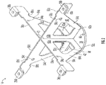
- FIGURE 2 illustrates mounting bracket 14 according to one embodiment of the present invention.
- mounting bracket 14 has base plate 38, inner web 40, outer web 42, top chords 50a, 50b, 50c, and 50d, and bottom chords 52a, 52b, 52c, and 52d.
- Top chords 50a, 50b, 50c, and 50d all extend from a first end to a second end.
- Top chords 50a, 50b, 50c, and 50d may be of any suitable shape including a substantially circular or rectangular shape.
- top chords 50a, 50b, 50c, and 50d may all be oriented in a direction transverse to base plate 38. In this manner, top chords 50a, 50b, 50c, and 50d provide structural integrity to mounting bracket 14 while minimally interfering with airflow into housing 12.
- top chords 50a, 50b, 50c, and 50d are coupled to mounting flanges 36a, 36b, 36c, and 36d respectively.
- the second end of each of top chords 50a, 50b, 50c, and 50d is coupled to inner web 40.
- top chords 50a and 50c may have grill mounting holes 54a and 54c respectively for supporting a grill that is placed upon mounting bracket 14.
- Top chords 50b and 50d may also have cable tie holes 56b and 56d and cable tie notches 58b and 58d respectively.
- Top chords 50a, 50b, 50c, and 50d may also have impeller clearance notches 60a, 60b, 60c, and 60d respectively.
- Inner web 40 may form the inner support for mounting bracket 14.
- Inner web 40 may comprise a number of inner chords 62a, 62b, 62c, and 62d (62a and 62d are not shown) that connect top chords 50a, 50b, 50c, and 50d to bottom chords 52a, 52b, 52c, and 52d respectively.
- One end of each of top chords 50a, 50b, 50c, and 50d may intersect at and be coupled to a first end of inner web 40.
- One end of each of bottom chords 52a, 52b, 52c, and 52d may intersect at and be coupled to a second end of inner web 40.
- outer web 42 may connect top chords 50a, 50b, 50c, and 50d to bottom chords 52a, 52b, 52c, and 52d.
- Outer web 42 may form the outer support for mounting bracket 14.
- Outer web 42 may comprise outer chords 64a, 64b, 64c, and 64d that connect one end of each of bottom chords 52a, 52b, 52c, and 52d to a portion of top chords 50a, 50b, 50c, and 50d respectively.
- outer chords 64a, 64b, 64c, and 64d are angled.
- outer chords 64a, 64b, 64c, and 64d may connect top chords 50a, 50b, 50c, and 50d to bottom chords 52a, 52b, 52c, and 52d in any suitable manner.
- Bottom chords 52a, 52b, 52c, and 52d all extend from a first end to a second end.
- Bottom chords 52a, 52b, 52c, and 52d may be of any suitable length including being shorter than, the same length as, or longer than top chords 50a, 50b, 50c, and 50d.
- bottom chords 52a, 52b, 52c, and 52d are all shorter than top chords 50a, 50b, 50c, and 50d.
- One end of each bottom chord 52a, 52b, 52c, and 52d is connected to outer web 42.
- the other end of each bottom chord 52a, 52b, 52c, and 52d is connected to inner web 40.
- Bottom chords 52a, 52b, 52c, and 52d may all be welded, screwed, or otherwise coupled to base plate 38 in any suitable manner.
- Base plate 38 may be any surface or plate that is coupled to bottom chords 52a, 52b, 52c, and 52d.
- Base plate 38 may be made of any material including a material that is different from the material forming the rest of mounting bracket 14.
- Base plate 38 may have a number of mounting holes 66.
- Base plate 38 may also have a cable clearance notch 68.
- base plate 38 may be formed by coupling multiple plates together.
- base plate 38 is shown in a circular shape, in various embodiments, base plate 38 may be of any suitable shape including an elliptical or oblong shape.
- FIGURE 3 illustrates one embodiment where impeller 16 coupled to motor 18 is mounted to mounting bracket 14.
- motor 18 is mounted to base plate 38 of mounting bracket 14.
- mounting bracket 14, impeller 16, and motor 18 are recessed into housing 12 through top portion 22.
- Impeller 16 is coupled to motor 18 so that at least a portion of motor 18 protrudes out from below impeller 16.
- Figure 3 also illustrates a zoomed-in view of impeller clearance notch 60d in relation to impeller blade 30.
- blades 30 of impeller 16 rotate around motor 18 and pass through impeller clearance notch 60d to avoid hitting mounting bracket 14.
- Impeller clearance notches 60a, 60b, 60c, and 60d thereby allow impeller blades 30 to be positioned close to top chords 50a, 50b, 50c, and 50d without coming in contact with those chords.
- top chords 50a, 50b, 50c, and 50d here are of a substantially rectangular shape and are oriented in a longitudinal direction.
- a cable 100 for powering motor 18 is coupled to motor 18.
- Cable 100 runs through cable clearance notch 68 and is tied down to top chord 50b by cable tie 102.
- Cable tie 102 is threaded through cable tie hole 56b and runs over cable 100.
- Cable tie 102 then runs through cable tie notch 58b to make a loop over top chord 50b.
- Cable tie 102 thereby securely fastens cable 100 to top chord 50b without interfering with air flow into housing 12 and keeps cable 100 out of impeller 16.
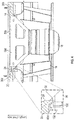
- FIGURE 4 further illustrates the embodiment of Figure 3 where mounting bracket 14 is coupled to housing cover 20 with inlet ring 24.
- Mounting bracket 14 is mounted onto housing cover 20 by fasteners attached to mounting flanges 36a, 36b, 36c, and 36d (36a and 36c are not shown).
- Figure 4 also illustrates a zoomed-in view of tolerance 150 between inlet ring 24 and impeller blade 30 as well as overlap 152 between blade 30 and inlet ring 24.
- motor 18 drives impeller 16, causing impeller 16 to rotate in either a clockwise or counter-clockwise direction.
- the rotation of impeller 16 pulls air into impeller inlet 28 in a longitudinal direction.
- the efficiency of impeller 16 is increased because tolerance 150 between impeller inlet 28 and inlet ring 24 can be minimized.
- Tolerance 150 is the gap between inlet ring 24 and impeller inlet 28 in a radial direction.
- lip 32 of inlet ring 24 protrudes into impeller inlet 28. Lip 32 thus prevents air pushed out by impeller blades 30 from being pulled back into impeller inlet 28.
- Tolerance 150 ensures that lip 32 of inlet ring 24 remains aligned with impeller inlet 28 even as impeller 16 moves or is displaced due to wear and tear.
- tolerance 150 increases, i.e. there is a greater gap between inlet ring 24 and impeller inlet 28, the surface area of impeller inlet 28 that is able to draw in air decreases. As this surface area decreases, the efficiency of impeller 16 decreases as well.
- tolerance 150 can be minimized because impeller 16, motor 18, and housing cover 20, including inlet ring 24, are all coupled to the same mounting bracket 14. Thus, if there is any displacement of housing cover 20, impeller 16 and inlet ring 24 are displaced in the same manner and they remain aligned with each other. Thus, it is not necessary to leave a large tolerance 150 between impeller inlet 28 and inlet ring 24 to ensure that impeller inlet 28 and inlet ring 24 remain aligned. Because tolerance 150 can be minimized, the efficiency of impeller 16 is maximized.
- lip 32 of inlet ring 24 can be placed close to the periphery of impeller inlet 28. Lip 32 prevents air pushed out of impeller 26 from getting pulled back into impeller inlet 28. Thus, the closer lip 32 is to the periphery of impeller inlet 28, the more efficiently lip 32 prevents air from re-entering impeller inlet 28. Because air cannot reenter impeller inlet 28 as more air is pushed out of impeller 16, the propelled air is forced to exit housing 12 through side opening 26 thereby increasing the efficiency of the overall air mover.
- this embodiment retains overlap 152 between blade 30 and inlet ring 24 despite displacement and deformation of housing 12 that may occur from time to time.
- housing cover 20 is positioned so that lip 32 of inlet ring 24 protrudes into impeller inlet 28.
- This overlap 152 ensures that air pushed out of blades 30 is not pulled back into impeller inlet 28.
- inlet ring 24 and impeller 16 are both coupled to mounting bracket 14, displacement of inlet ring 24, such as by deformations of housing cover 20, does not change the alignment of lip 32 with respect to impeller inlet 28. Accordingly, overlap 152 between lip 32 and impeller inlet 28 is not affected by any such displacements or deformations.
- This embodiment thus ensures the robustness of air mover 10 by maintaining its efficiency for a long period of time.
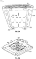
- FIGURE 5A illustrates housing 12 laying on its side showing the bottom of base portion 34 and side opening 26 of housing 12. As shown, base portion 34 has apertures 200. Base portion 34 also has protrusions 202 and legs 204.
- housing 12 sits on legs 204.
- impeller 16 pushes air out of impeller inlet 28
- most of the air flows out of housing 12 through side opening 26.
- FIGURE 5B illustrates housing cover 20 showing inlet ring 24, lip 32, bracket mounting holes 44a, 44b, 44c, and 44d, recesses 206, and grill 208.
- Housing cover 20 may couple with mounting bracket 14 by fastening mounting flanges 36a, 36b, 36c, and 36d to bracket mounting holes 44a, 44b, 44c, and 44d.
- protrusions 202 of base portion 34 may be placed inside recesses 206 to stack multiple air movers 10.
- grill 208 may be placed inside inlet ring 24 to prevent foreign objects from entering housing 12.
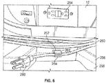
- FIGURE 6 illustrates one side of housing 12 showing a power cord 250, a power cord clip 252, and a built-in outlet 254.
- power cord 250 is coupled to motor 18 through housing 12.
- power cord 250 is coupled to housing 12 above power cord clip 252.
- base portion 34 of housing 12 is formed by coupling a housing body portion 256 to a housing bottom portion 258.
- Power cord 250 may be any cable that can provide electric power to motor 18. In various embodiments, power cord 250 may be coupled to any suitable plug 260.
- Power cord clip 252 may be any clip in which power cord 250 may be placed for storing power cord 250.
- Power cord clip 252 may be formed of a top half 262 and a bottom half 264.
- top half 262 may be coupled to body portion 256 of housing 12 while bottom half 264 may be coupled to bottom portion 258 of housing 12.
- Power cord clip 252 may be placed above or below power cord 250 at its coupling point to housing 12 so that power cord 250 may be wrapped in either a clockwise or counter-clockwise direction and terminate close enough to clip 252 to be positioned inside clip 252 for storage.
- Outlet 254 may be any suitable interface for connecting an electrically operated device to a power supply. Outlet 254 may direct a portion of the power drawn by power cord 250 to another electrical device.
- power cord 250 may be coupled to motor 18 at one end and a power source by plug 260. Motor 18 may draw power from the power source and power cord 250 may transfer the power from the power source to motor 18. Power cord 250 may also be coupled to outlet 254 so that when power cord 250 is coupled to a power source, a user may couple another electrical device to outlet 254 and draw power from outlet 254.
Landscapes
- Engineering & Computer Science (AREA)
- Mechanical Engineering (AREA)
- General Engineering & Computer Science (AREA)
- Structures Of Non-Positive Displacement Pumps (AREA)
Description
- This disclosure relates generally to electro-mechanical devices and specifically to a fan and mounting bracket for an air mover.
- It is often necessary to dry, cool, or heat various surfaces by exposing them to propelled air. Current approaches for exposing such surfaces to propelled air are inefficient, ineffective, and generally unreliable. It is thus desirable to create a reliable and efficient system that can expose appropriate surfaces to propelled air for suitable periods of time.
-
US 2012/141264 A1 andUS 2006/051205 A1 disclose examples of blowers. - According to embodiments of the present disclosure, disadvantages and problems associated with previous air movers may be reduced or eliminated.
- An air mover comprises a housing with a top portion. A mounting bracket is recessed into the housing through the top portion of the housing. The mounting bracket comprises a plurality of top chords intersecting at a first portion of an inner web and a plurality of bottom chords intersecting at a second portion of the inner web wherein the inner web comprises a plurality of vertical chords extending from the first portion of the inner web to the second portion of the inner web. Each of the plurality of top chords has an impeller clearance notch and a mounting flange. The mounting bracket also comprises a plurality of outer chords wherein each outer chord extends from a corresponding top chord to a corresponding bottom chord. The mounting bracket also has a base plate coupled to the plurality of bottom chords. A motor is coupled to the base plate of the mounting bracket. An impeller is coupled to the motor. The impeller comprises an inlet and a plurality of blades. The impeller is positioned so that a portion of the plurality of blades pass through the plurality of impeller clearance notches as the impeller rotates. The air mover further comprises a housing cover that has an inlet ring positioned on the top portion of the housing. The housing cover is coupled to the mounting bracket via the mounting flanges and a portion of the inlet ring protrudes into the impeller inlet inside the housing.
- An air moving apparatus comprises a housing having a top portion, a mounting bracket recessed into the top portion of the housing, the mounting bracket comprising a plurality of impeller clearance notches, a motor coupled to the mounting bracket, an impeller coupled to the motor wherein the impeller comprises an inlet and a plurality of blades; the impeller being positioned so that a portion of the plurality of blades pass through one or more of the impeller clearance notches in the mounting bracket as the impeller rotates and a housing cover having an inlet ring. The housing cover is positioned on the top portion of the housing and is coupled to the mounting bracket. The inlet ring is positioned such that the inlet ring overlaps with at least a portion of the impeller blades in a longitudinal direction and there is a tolerance between the inlet ring and the impeller blades in a radial direction.
- A method of assembling an air mover comprises: coupling a motor to a base plate of a mounting bracket, the mounting bracket comprising: a plurality of top chords intersecting at a first portion of an inner web and a plurality of bottom chords intersecting at a second portion of the inner web wherein the inner web comprises a plurality of vertical chords extending from the first portion of the inner web to the second portion of the inner web; the plurality of top chords each having an impeller clearance notch and a mounting flange; a plurality of outer chords wherein each outer chord extends from a corresponding top chord to a corresponding bottom chord; and the base plate coupled to the plurality of bottom chords; coupling an impeller to the motor wherein the impeller comprises an inlet and a plurality of blades, the impeller being positioned so that a portion of the plurality of blades pass through the plurality of impeller clearance notches of the mounting bracket as the impeller rotates; recessing the mounting bracket into a housing through a top portion of the housing placing a housing cover onto the top portion of the housing, the housing cover comprising an inlet ring; and coupling the mounting bracket via the mounting flanges onto the housing cover so that a portion of the inlet ring protrudes into the impeller inlet inside the housing.
- Certain embodiments may provide one or more advantages. One advantage of one embodiment may include increased efficiency of the air mover by maximizing the cross-sectional diameter of impeller inlet through which air can flow into the impeller. Another advantage of one embodiment may include increased robustness of the air mover that may be achieved by maintaining the alignment of the impeller inlet with the inlet ring over a long period of time.
- Various embodiments of the invention may include none, some, or all of the above technical advantages. One or more other technical advantages may be readily apparent to one skilled in the art from the figures, descriptions, and claims included herein.
- To provide a more complete understanding of the present disclosure and the features and advantages thereof, reference is made to the following description taken in conjunction with the accompanying drawings, in which:
-
FIGURE 1 illustrates an exploded view of an air mover and its impeller assembly; -
FIGURE 2 illustrates a perspective view of a mounting bracket; -
FIGURE 3 illustrates a side view of a mounting bracket coupled with an impeller and a motor; -
FIGURE 4 illustrates a side view of the mounting bracket mounted to an impeller, a motor, and a housing cover with an inlet ring; -
FIGURE 5A illustrates the bottom of an air mover; -
FIGURE 5B illustrates the top cover of an air mover; and -
FIGURE 6 illustrates a side view of an air mover housing. -
FIGURE 1 illustrates an exploded view ofair mover 10 comprisinghousing 12,mounting bracket 14,impeller 16,motor 18, andhousing cover 20.Housing cover 20 has aninlet ring 24 and is placed on atop portion 22 ofhousing 12.Impeller 16 andmotor 18 are coupled to each other and mounted to mountingbracket 14. Themounting bracket 14,impeller 16, andmotor 18 assembly is recessed intohousing 12 throughtop portion 22 ofhousing 12.Mounting bracket 14 is then coupled tohousing cover 20. This unique and novel configuration has several advantages, some of which are summarized here and described in greater detail below. - First, recessing
impeller 16 andmotor 18 throughtop portion 22 ofhousing 12 provides flexibility in sizinginlet ring 24. This flexibility allows for maximizing the area ofimpeller 16 into which unrestricted air flows by minimizing the gap betweenimpeller 16 andinlet ring 24. Second, this configuration increases the efficiency and robustness ofair mover 10 by maintaining the alignment ofimpeller 16 with respect toinlet ring 24 even when different portions ofhousing 12 are displaced or deformed. Becausehousing cover 20,motor 18, andimpeller 16 are all coupled to mountingbracket 14, even ifhousing cover 20 that is coupled tohousing 12 is displaced or deformed,impeller 16 remains aligned withinlet ring 24. And any damage to other portions ofhousing 12 does not affect the alignment ofimpeller 16 with respect toinlet ring 24. - In this embodiment,
housing 12 has atop portion 22 and a side opening 26.Impeller 16 has aninner portion 28 that is surrounded byblades 30.Motor 18 is placed insideinner portion 28 ofimpeller 16.Impeller 16 is then coupled tomotor 18 and bothmotor 18 andimpeller 16 are coupled to mountingbracket 14. As described in greater detail with reference toFigure 3 below,motor 18 andimpeller 16 are coupled to mountingbracket 14 so thatmotor 18 is recessed withinimpeller 16. In this embodiment,motor 18 is recessed withinimpeller 16 such thatmotor 18 protrudes out from the bottom ofimpeller 16. The coupledimpeller 16 andmotor 18 assembly is lowered intohousing 12 throughtop portion 22. Once theimpeller 16 andmotor 18 assembly is lowered intohousing 12,housing cover 20 is placed upontop portion 22.Mounting bracket 14 is then coupled tohousing cover 20.Housing cover 20 is positioned ontop portion 22 such thatinlet ring 24 ofhousing cover 20 aligns withinner portion 28 ofimpeller 16. In this manner, whenhousing cover 20 is placed upontop portion 22 and is coupled to mountingbracket 14,lip 32 ofinlet ring 24 protrudes intoinner portion 28 ofimpeller 16. -
Housing 12 may be any support structure that can house the components ofair mover 10. In one embodiment,housing 12 may have atop portion 22, side opening 26, and abase portion 34. Air may flow intotop portion 22 and out of side opening 26.Housing 12 may be formed of any combination of materials. Different portions ofhousing 12 may be formed of different materials. In various embodiments,housing 12 is made of rigid or flexible polymers. Side opening 26 ofhousing 12 may have a grill for preventing foreign objects from entering intohousing 12. As described in greater detail with respect toFigure 5A below,base portion 34 may have protrusions to facilitate stackingmultiple air movers 10, andbase portion 34 may have apertures for air flow out ofhousing 12. -
Housing cover 20 may be placed upontop portion 22 ofhousing 12. In various embodiments,housing cover 20 may be made of various materials including materials that are different from thematerial forming housing 12.Housing cover 20 may be made of a rigid or a flexible polymer.Housing cover 20 may have aninlet ring 24.Inlet ring 24 may be any opening that allows fluid to flow intohousing 12 throughhousing cover 20. In some embodiments,inlet ring 24 may be formed withinhousing cover 20 while in otherembodiments inlet ring 24 may be removably coupled tohousing cover 20. In all such embodiments,inlet ring 24 ofhousing cover 20 may have alip 32.Lip 32 may protrude intohousing 12 whenhousing cover 20 is placed upontop portion 22. Althoughinlet ring 24 is shown as being circular,inlet ring 24 may be of any suitable shape including any oblong or elliptical shape.Housing cover 20 may havebracket mounting holes housing cover 20 to mountingbracket 14. When coupled tohousing cover 20, a portion of mountingbracket 14 may pass through notches ininlet ring 24. - Mounting
bracket 14 may be any structure that can supportimpeller 16 andmotor 18 and be coupled tohousing cover 20. Mountingbracket 14 may be made of any suitable material. Different portions of mountingbracket 14 may be made of any suitable material. In one embodiment, mountingbracket 14 may be made of a sturdy, low-gauge metal. Mountingbracket 14 may have mountingflanges base plate 38. As described in greater detail with respect withFigure 2 below, mountingflanges base plate 38 by aninner web 40 and anouter web 42. Mountingbracket 14 may be coupled tohousing cover 20 by fastening mountingflanges bracket mounting holes -
Impeller 16 may be any rotor that has aninlet 28 surrounded byblades 30.Impeller 16 may be made of any material including any metallic material or any rigid or flexible polymer.Blades 30 may be arranged in any configuration so that whenblades 30 rotate, air entersimpeller 16 throughinlet 28 and is pushed out radially through side opening 26 ofhousing 12.Inlet 28 andblades 30 may be of any suitable size. In some embodiments,inlet 28 may be large enough to supportmotor 18 andmotor 18 may be placed insideinlet 28. In such embodiments,impeller 16 may be directly coupled tomotor 18. In other embodiments,impeller 16 may be coupled tomotor 18 by a driving shaft.Impeller inlet 28 may also have a lip so that whenhousing cover 20 is placed upontop portion 22,inlet ring 24 ofhousing cover 20 protrudes into the lip ofimpeller inlet 28. -
Motor 18 may be any electromechanical device that is capable of rotatingimpeller 16. In various embodiments,motor 18 may be powered by either direct current or alternating current. In some embodiments,motor 18 may causeimpeller 16 to rotate in a clockwise direction while in other embodiments,motor 18 may causeimpeller 16 to rotate in a counter-clockwise direction.Motor 18 may have variable speeds of rotation which may depend upon the amount of power that the motor draws. - In operation of one embodiment of the present disclosure,
motor 18 is powered by an electrical source and rotates in a clockwise or counter-clockwise direction.Motor 18, which is coupled toimpeller 16, is placed insidehousing 12.Motor 18drives impeller 16 and causesimpeller 16 to rotate as well. The rotation ofimpeller 16 pulls air intoimpeller inlet 28 throughtop portion 22.Housing cover 20, withinlet ring 24, is placed upontop portion 22.Impeller 16 is placed insidehousing 12 so thatimpeller inlet 28 is substantially aligned withinlet ring 24 in a longitudinal direction. Thus, whenimpeller 16 rotates, air entersimpeller inlet 28 throughinlet ring 24. After the air has been pulled intoimpeller inlet 28, it is pushed out in a radial direction byimpeller blades 30.Lip 32 ofinlet ring 24, which protrudes intoimpeller inlet 28, prevents air that has been pushed out ofimpeller 16 from being pulled back intoimpeller inlet 28. Becauseimpeller 16 is substantially aligned with side opening 26 ofhousing 12 in a radial direction, the propelled air is pushed out ofhousing 12 throughside opening 26. - In this embodiment,
motor 18 andimpeller 16 are coupled to mountingbracket 14. The coupled mountingbracket 14,impeller 16, andmotor 18 assembly is recessed intohousing 12 throughtop portion 22 ofhousing 12. Mountingbracket 14 is also coupled tohousing cover 20. This embodiment provides several technocal advantages. For example, this embodiment advantageously provides flexibility in sizinginlet ring 24. In this embodiment,housing cover 20 hasinlet ring 24 and is also coupled to mountingbracket 14.Motor 18 is coupled tobase plate 38 of mountingbracket 14 andimpeller 16 is coupled tomotor 18. As such, ifhousing cover 20 is compressed, such as by the placement of heavy objects onhousing 12, bothinlet ring 24 andimpeller 16 move in substantially the same manner. Becausehousing cover 20 andimpeller 16 are connected by mountingbracket 14, any displacement ofhousing cover 20 also displacesimpeller 16. Accordingly, displacement ofhousing cover 20 does not affect the alignment ofinlet ring 24 andimpeller inlet 28. Thus, as explained in greater detail with respect toFigure 4 below, the tolerance betweeninlet ring 24 andimpeller inlet 28 can be minimized. In contrast, other air movers where impellers are not mounted to a mountingbracket 14 that is coupled to thehousing cover 20 of anair mover housing 12 must provide a greater tolerance betweenimpeller 16 andinlet ring 14 because any deformation or displacement of the top of those air movers changes the alignment of the inlet rings of those movers with respect to the impellers. As discussed in greater detail with respect toFigure 4 below, minimizing the tolerance betweeninlet ring 24 andimpeller inlet 28 maximizes the cross-sectional area ofinlet ring 24 which allows for greater flow of air intoimpeller inlet 28 and increases the overall efficiency ofair mover 10. - Another advantage of this embodiment is that the low tolerance needed between
inlet ring 24 andimpeller inlet 28 allows for the placement oflip 32 ofinlet ring 24 close to the periphery ofimpeller inlet 28.Lip 32 prevents air pushed out ofimpeller 26 from getting pulled back intoimpeller inlet 28. Thecloser lip 32 is to the periphery ofimpeller inlet 28, the more efficientlylip 32 can prevent air from re-enteringimpeller inlet 28. This aspect of the present embodiment also increases the efficiency of the air mover. - In this embodiment, the robustness of
air mover 10 is also improved because the present embodiment maintains the alignment ofimpeller 16 with respect toinlet ring 24 even whenhousing 12 is damaged or deformed. As described earlier,inlet ring 24 may havelip 32 which protrudes intoimpeller inlet 28. Becauseinlet ring 24 andimpeller 16 are both coupled to mountingbracket 14, displacement ofinlet ring 24, such as by deformations ofhousing cover 20, does not change the alignment oflip 32 with respect toimpeller inlet 28. Accordingly, the overlap betweenlip 32 andimpeller inlet 28 is maintained. -
FIGURE 2 illustrates mountingbracket 14 according to one embodiment of the present invention. In this embodiment, mountingbracket 14 hasbase plate 38,inner web 40,outer web 42,top chords bottom chords -
Top chords Top chords top chords top chords base plate 38. In this manner,top chords bracket 14 while minimally interfering with airflow intohousing 12. In one embodiment, the first end of each oftop chords flanges top chords inner web 40. In some embodiments,top chords 50a and 50c may havegrill mounting holes 54a and 54c respectively for supporting a grill that is placed upon mountingbracket 14.Top chords cable tie notches Top chords impeller clearance notches -
Inner web 40 may form the inner support for mountingbracket 14.Inner web 40 may comprise a number ofinner chords top chords bottom chords top chords inner web 40. One end of each ofbottom chords inner web 40. Although this embodiment shows aninner web 40, other embodiments may not have aninner web 40. In such embodiments,outer web 42 may connecttop chords bottom chords -
Outer web 42 may form the outer support for mountingbracket 14.Outer web 42 may compriseouter chords bottom chords top chords outer chords outer chords top chords bottom chords -
Bottom chords Bottom chords top chords bottom chords top chords bottom chord outer web 42. The other end of eachbottom chord inner web 40.Bottom chords base plate 38 in any suitable manner. -
Base plate 38 may be any surface or plate that is coupled tobottom chords Base plate 38 may be made of any material including a material that is different from the material forming the rest of mountingbracket 14.Base plate 38 may have a number of mounting holes 66.Base plate 38 may also have acable clearance notch 68. In some embodiments,base plate 38 may be formed by coupling multiple plates together. Althoughbase plate 38 is shown in a circular shape, in various embodiments,base plate 38 may be of any suitable shape including an elliptical or oblong shape. -
FIGURE 3 illustrates one embodiment whereimpeller 16 coupled tomotor 18 is mounted to mountingbracket 14. In this embodiment,motor 18 is mounted tobase plate 38 of mountingbracket 14. As discussed with respect toFigure 1 above, mountingbracket 14,impeller 16, andmotor 18 are recessed intohousing 12 throughtop portion 22.Impeller 16 is coupled tomotor 18 so that at least a portion ofmotor 18 protrudes out from belowimpeller 16. -
Figure 3 also illustrates a zoomed-in view ofimpeller clearance notch 60d in relation toimpeller blade 30. As illustrated in the zoomed-in portion ofFigure 3 ,blades 30 ofimpeller 16 rotate aroundmotor 18 and pass throughimpeller clearance notch 60d to avoid hitting mountingbracket 14.Impeller clearance notches impeller blades 30 to be positioned close totop chords top chords - In this figure, a
cable 100 for poweringmotor 18 is coupled tomotor 18.Cable 100 runs throughcable clearance notch 68 and is tied down totop chord 50b bycable tie 102.Cable tie 102 is threaded throughcable tie hole 56b and runs overcable 100.Cable tie 102 then runs throughcable tie notch 58b to make a loop overtop chord 50b.Cable tie 102 thereby securely fastenscable 100 totop chord 50b without interfering with air flow intohousing 12 and keepscable 100 out ofimpeller 16. -
FIGURE 4 further illustrates the embodiment ofFigure 3 where mountingbracket 14 is coupled tohousing cover 20 withinlet ring 24. Mountingbracket 14 is mounted ontohousing cover 20 by fasteners attached to mountingflanges Figure 4 also illustrates a zoomed-in view oftolerance 150 betweeninlet ring 24 andimpeller blade 30 as well asoverlap 152 betweenblade 30 andinlet ring 24. - In operation,
motor 18drives impeller 16, causingimpeller 16 to rotate in either a clockwise or counter-clockwise direction. The rotation ofimpeller 16 pulls air intoimpeller inlet 28 in a longitudinal direction. Air flows intoimpeller 16 relatively unobstructed becausemotor 18 is recessed belowimpeller 16 and becausetop chords top chords motor 18. - As mentioned above in relation to
Figure 1 , this embodiment provides several technical advantages. First, in this embodiment, the efficiency ofimpeller 16 is increased becausetolerance 150 betweenimpeller inlet 28 andinlet ring 24 can be minimized.Tolerance 150 is the gap betweeninlet ring 24 andimpeller inlet 28 in a radial direction. In this embodiment,lip 32 ofinlet ring 24 protrudes intoimpeller inlet 28.Lip 32 thus prevents air pushed out byimpeller blades 30 from being pulled back intoimpeller inlet 28.Tolerance 150 ensures thatlip 32 ofinlet ring 24 remains aligned withimpeller inlet 28 even asimpeller 16 moves or is displaced due to wear and tear. Astolerance 150 increases, i.e. there is a greater gap betweeninlet ring 24 andimpeller inlet 28, the surface area ofimpeller inlet 28 that is able to draw in air decreases. As this surface area decreases, the efficiency ofimpeller 16 decreases as well. - In this embodiment,
tolerance 150 can be minimized becauseimpeller 16,motor 18, andhousing cover 20, includinginlet ring 24, are all coupled to the same mountingbracket 14. Thus, if there is any displacement ofhousing cover 20,impeller 16 andinlet ring 24 are displaced in the same manner and they remain aligned with each other. Thus, it is not necessary to leave alarge tolerance 150 betweenimpeller inlet 28 andinlet ring 24 to ensure thatimpeller inlet 28 andinlet ring 24 remain aligned. Becausetolerance 150 can be minimized, the efficiency ofimpeller 16 is maximized. - Second, because this embodiment minimizes
tolerance 150,lip 32 ofinlet ring 24 can be placed close to the periphery ofimpeller inlet 28.Lip 32 prevents air pushed out ofimpeller 26 from getting pulled back intoimpeller inlet 28. Thus, thecloser lip 32 is to the periphery ofimpeller inlet 28, the more efficientlylip 32 prevents air from re-enteringimpeller inlet 28. Because air cannot reenterimpeller inlet 28 as more air is pushed out ofimpeller 16, the propelled air is forced to exithousing 12 throughside opening 26 thereby increasing the efficiency of the overall air mover. - Third, this embodiment retains
overlap 152 betweenblade 30 andinlet ring 24 despite displacement and deformation ofhousing 12 that may occur from time to time. In this embodiment,housing cover 20 is positioned so thatlip 32 ofinlet ring 24 protrudes intoimpeller inlet 28. A portion ofblades 30, which form the periphery ofimpeller inlet 28, overlap withlip 32 wherelip 32 protrudes intoimpeller inlet 28 in a longitudinal direction. Thisoverlap 152 ensures that air pushed out ofblades 30 is not pulled back intoimpeller inlet 28. As described earlier, becauseinlet ring 24 andimpeller 16 are both coupled to mountingbracket 14, displacement ofinlet ring 24, such as by deformations ofhousing cover 20, does not change the alignment oflip 32 with respect toimpeller inlet 28. Accordingly, overlap 152 betweenlip 32 andimpeller inlet 28 is not affected by any such displacements or deformations. This embodiment thus ensures the robustness ofair mover 10 by maintaining its efficiency for a long period of time. -
FIGURE 5A illustrateshousing 12 laying on its side showing the bottom ofbase portion 34 and side opening 26 ofhousing 12. As shown,base portion 34 hasapertures 200.Base portion 34 also hasprotrusions 202 andlegs 204. - In operation,
housing 12 sits onlegs 204. Asimpeller 16 pushes air out ofimpeller inlet 28, most of the air flows out ofhousing 12 throughside opening 26. Some air, however, also flows out ofapertures 200 to dry, heat, or cool the surface beneathair mover 10. -
FIGURE 5B illustrateshousing cover 20showing inlet ring 24,lip 32,bracket mounting holes grill 208.Housing cover 20 may couple with mountingbracket 14 by fastening mountingflanges bracket mounting holes protrusions 202 ofbase portion 34 may be placed insiderecesses 206 to stackmultiple air movers 10. In one embodiment,grill 208 may be placed insideinlet ring 24 to prevent foreign objects from enteringhousing 12. -
FIGURE 6 illustrates one side ofhousing 12 showing apower cord 250, apower cord clip 252, and a built-inoutlet 254. In this embodiment,power cord 250 is coupled tomotor 18 throughhousing 12. As shown,power cord 250 is coupled tohousing 12 abovepower cord clip 252. Further, in this embodiment,base portion 34 ofhousing 12 is formed by coupling ahousing body portion 256 to ahousing bottom portion 258. -
Power cord 250 may be any cable that can provide electric power tomotor 18. In various embodiments,power cord 250 may be coupled to anysuitable plug 260. -
Power cord clip 252 may be any clip in whichpower cord 250 may be placed for storingpower cord 250.Power cord clip 252 may be formed of atop half 262 and abottom half 264. For ease of machining and for flexibility ofclip 252,top half 262 may be coupled tobody portion 256 ofhousing 12 whilebottom half 264 may be coupled tobottom portion 258 ofhousing 12.Power cord clip 252 may be placed above or belowpower cord 250 at its coupling point tohousing 12 so thatpower cord 250 may be wrapped in either a clockwise or counter-clockwise direction and terminate close enough to clip 252 to be positioned insideclip 252 for storage. -
Outlet 254 may be any suitable interface for connecting an electrically operated device to a power supply.Outlet 254 may direct a portion of the power drawn bypower cord 250 to another electrical device. - In operation,
power cord 250 may be coupled tomotor 18 at one end and a power source byplug 260.Motor 18 may draw power from the power source andpower cord 250 may transfer the power from the power source tomotor 18.Power cord 250 may also be coupled tooutlet 254 so that whenpower cord 250 is coupled to a power source, a user may couple another electrical device tooutlet 254 and draw power fromoutlet 254. - Modifications, additions, or omissions may be made to the systems and apparatuses described herein without departing from the scope of the disclosure. The components of the systems and apparatuses may be integrated or separated.
- Although several embodiments have been illustrated and described in detail, it will be recognized that substitutions and alterations are possible without departing from the scope of the present disclosure, as defined by the appended claims.
Claims (19)
- An air mover (10) comprising:a housing (12) having a top portion (22);a mounting bracket (14) recessed into the top portion (22) of the housing (12), the mounting bracket (14) comprising:a plurality of top chords (50a, 50b, 50c, 50d) intersecting at a first portion of an inner web (40) and a plurality of bottom chords (52a, 52b, 52c, 52d) intersecting at a second portion of the inner web (40) wherein the inner web (40) comprises a plurality of vertical chords (62a, 62b, 62c, 62d) extending from the first portion of the inner web (40) to the second portion of the inner web (40);the plurality of top chords (50a, 50b, 50c, 50d) each having an impeller clearance notch (60a, 60b, 60c, 60d) and a mounting flange (36a, 36b, 36c, 36d);a plurality of outer chords (64a, 64b, 64c, 64d) wherein each outer chord (64a, 64b, 64c, 64d) extends from a corresponding top chord (50a, 50b, 50c, 50d) to a corresponding bottom chord (52a, 52b, 52c, 52d); anda base plate (38) coupled to the plurality of bottom chords (52a, 52b, 52c, 52d);a motor (18) coupled to the base plate (38) of the mounting bracket (14);an impeller (16) coupled to the motor (18) wherein the impeller (16) comprises an inlet (28) and a plurality of blades (30), the impeller (16) being positioned so that a portion of the plurality of blades (30) pass through the plurality of impeller clearance notches (60a, 60b, 60c, 60d) as the impeller (16) rotates; anda housing cover (20) having an inlet ring (24) positioned on the top portion (22) of the housing (12) wherein the motor (18) and the impeller (16) are coupled to the housing cover (20) via the mounting bracket (14) using the mounting flanges (36a, 36b, 36c, 36d) and a portion of the inlet ring (24) protrudes into the impeller inlet (28) inside the housing (12).
- The air mover of claim 1, wherein the base plate (38) has a cable clearance notch (66).
- The air mover of claim 1 or claim 2, wherein the plurality of top chords (50a, 50b, 50c, 50d) further comprise a plurality of notches (54a, 54b, 54c, 54d) for positioning a grill (208).
- The air mover of one of claims 1 to 3, further comprising a power cord (250) that is coupled to the housing (12) directly above a power cord clip (252) and the power cord clip (252) is operable to hold the power cord (250).
- The air mover of one of claims 1 to 4, wherein the housing cover (20) comprises a plurality of recesses (206) and wherein the housing (12) further comprises a base portion (34) having a plurality of protrusions (202), the protrusions (202) being operable to fit within the recesses (206) of another housing (12) to stack a plurality of air movers.
- The air mover of claim 5, wherein the base portion (34) of the housing further comprises a plurality of apertures (200) for air flow out of the housing.
- The air mover of one of claims 1 to 6, wherein the mounting bracket (38) further comprises a plurality of cable tie locating holes (56) and cable tie locating notches (58a, 58b, 58c, 58d) for securing a cable with a fastener.
- The air mover of one of claims 1 to 7, wherein the impeller inlet (28) has a lip and the inlet ring (24) of the housing cover (20) protrudes into the impeller inlet lip so that airflow into impeller inlet (28) through the inlet ring (24) is increased and extraneous airflow into the impeller inlet (28) is decreased.
- The air mover of one of claims 1 to 8, wherein the inlet ring (24) of the housing cover has a lip (32) and the inlet ring lip (32) protrudes into the impeller inlet (28) so that airflow into impeller inlet (28) through the inlet ring (24) is increased and extraneous airflow into the impeller inlet (28) is decreased.
- A method of assembling an air mover (10) according to claim 1 comprising:coupling a motor (18) to a base plate (38) of a mounting bracket (14), the mounting bracket (14) comprising:a plurality of top chords (50a, 50b, 50c, 50d) intersecting at a first portion of an inner web (40) and a plurality of bottom chords (52a, 52b, 52c, 52d) intersecting at a second portion of the inner web (40) wherein the inner web (40) comprises a plurality of vertical chords (62a, 62b, 62c, 62d) extending from the first portion of the inner web (40) to the second portion of the inner web (40);the plurality of top chords (50a, 50b, 50c, 50d) each having an impeller clearance notch (60a, 60b, 60c, 60d) and a mounting flange (36a, 36b, 36c, 36d);a plurality of outer chords (64a, 64b, 64c, 64d) wherein each outer chord (64a, 64b, 64c, 64d) extends from a corresponding top chord (50a, 50b, 50c, 50d) to a corresponding bottom chord (52a, 52b, 52c, 52d); andthe base plate (38) coupled to the plurality of bottom chords(52a, 52b, 52c, 52d);coupling an impeller (16) to the motor (18) wherein the impeller (16) comprises an inlet (28) and a plurality of blades (30), the impeller (16) being positioned so that a portion of the plurality of blades (30) pass through the plurality of impeller clearance notches (60a, 60b, 60c, 60d) of the mounting bracket (14) as the impeller (16) rotates;recessing the mounting bracket (14) into a housing (12) through a top portion (22) of the housing (12);placing a housing cover (20) onto the top portion (22) of the housing (12), the housing cover (20) comprising an inlet ring (24) ; andcoupling the mounting bracket (14) via the mounting flanges (36a, 36b, 36c, 36d) onto the housing cover (20) so that a portion of the inlet ring (24) protrudes into the impeller inlet (28) inside the housing (12).
- The method of claim 10, wherein the base plate (38) has a cable clearance notch (66a, 66b, 66c, 66d).
- The method of claim 10 or claim 11, wherein the plurality of top chords (50a, 50b, 50c, 50d) further comprise a plurality of notches (54a, 54b, 54c, 54d) for positioning a grill (208).
- The method of one of claims 10 to 12, further comprising a power cord (250) that is coupled to the housing (12) directly above a power cord clip (252) and the power cord clip (252) is operable to hold the power cord (250).
- The method of one of claims 10 to 13, wherein the housing cover (20) comprises a plurality of recesses (206) and wherein the housing (12) further comprises a base portion (34) having a plurality of protrusions (202), the protrusions (202) being operable to fit within the recesses (206) of another housing (12) to stack a plurality of air movers (10).
- The method of one of claims 10 to 14, wherein the base portion (38) of the housing (12) further comprises a plurality of apertures (200) for air flow out of the housing (12).
- The method of one of claims 10 to 15, wherein the mounting bracket (14) further comprises a plurality of cable tie locating holes (56) and cable tie locating notches (58a, 58b, 58c, 58d) for securing a cable with a fastener.
- The method of one of claims 10 to 16, wherein the impeller inlet (28) has a lip and the inlet ring (24) of the housing cover (20) protrudes into the impeller inlet lip so that airflow into impeller inlet (28) through the inlet ring (24) is increased and extraneous airflow into the impeller inlet (28) is decreased.
- An air moving apparatus (10) comprising:a housing (12) having a top portion (22);a mounting bracket (14) recessed into the top portion (22) of the housing (12), the mounting bracket (14) comprising a plurality of impeller clearance notches (60a, 60b, 60c, 60d);a motor (18) coupled to the mounting bracket (14);an impeller (16) coupled to the motor (18) wherein the impeller (16) comprises an inlet (28) and a plurality of blades (30); the impeller (16) being positioned so that a portion of the plurality of blades (30) pass through one or more of the impeller clearance notches (60a, 60b, 60c, 60d) in the mounting bracket (14) as the impeller (16) rotates; anda housing cover (20) having an inlet ring (24), the housing cover (20) being positioned on the top portion (22) of the housing (12) and being coupled to the mounting bracket (14), the inlet ring (24) being positioned such that the inlet ring (14) overlaps with at least a portion of the impeller blades (30) in a longitudinal direction and there is a tolerance between the inlet ring (24) and the impeller blades (30) in a radial direction.
- The apparatus of claim 18, wherein the impeller (16) has a lip and there is an overlap between the inlet ring (24) and the impeller lip in a longitudinal direction and there is a tolerance between the inlet ring (24) and the impeller lip in the radial direction.
Applications Claiming Priority (1)
| Application Number | Priority Date | Filing Date | Title |
|---|---|---|---|
| US14/707,805 US10161417B2 (en) | 2015-05-08 | 2015-05-08 | Fan and mounting bracket for an air mover |
Publications (2)
| Publication Number | Publication Date |
|---|---|
| EP3091236A1 EP3091236A1 (en) | 2016-11-09 |
| EP3091236B1 true EP3091236B1 (en) | 2018-11-21 |
Family
ID=55442738
Family Applications (1)
| Application Number | Title | Priority Date | Filing Date |
|---|---|---|---|
| EP16157715.0A Not-in-force EP3091236B1 (en) | 2015-05-08 | 2016-02-26 | Fan and mounting bracket for an air mover |
Country Status (5)
| Country | Link |
|---|---|
| US (2) | US10161417B2 (en) |
| EP (1) | EP3091236B1 (en) |
| CN (1) | CN106122106B (en) |
| AU (1) | AU2016200806B2 (en) |
| CA (2) | CA2920570C (en) |
Families Citing this family (8)
| Publication number | Priority date | Publication date | Assignee | Title |
|---|---|---|---|---|
| DE102017115214A1 (en) * | 2017-02-23 | 2018-08-23 | Ebm-Papst Landshut Gmbh | Connection unit for a blower |
| CN107461808A (en) * | 2017-07-25 | 2017-12-12 | 广东美的制冷设备有限公司 | Machine and air conditioner in heat exchanger assembly, vertical air conditioner |
| JP7065272B2 (en) * | 2018-02-26 | 2022-05-12 | パナソニックIpマネジメント株式会社 | Blower |
| USD890176S1 (en) * | 2018-12-29 | 2020-07-14 | Suntec Industries (H.K.) Ltd. | Air mover |
| USD906509S1 (en) * | 2019-01-11 | 2020-12-29 | O2Cool, Llc | Fan |
| US10968920B2 (en) * | 2019-04-08 | 2021-04-06 | Johnson Controls Technology Company | Motor mount for HVAC system |
| DE102019119750A1 (en) * | 2019-07-22 | 2021-01-28 | Ebm-Papst Mulfingen Gmbh & Co. Kg | Fastening device for fastening a fan to a support structure |
| USD1118890S1 (en) * | 2023-06-20 | 2026-03-17 | Better Cleaning Systems, Inc. | Air mover |
Citations (1)
| Publication number | Priority date | Publication date | Assignee | Title |
|---|---|---|---|---|
| WO2015062127A1 (en) * | 2013-10-30 | 2015-05-07 | 中山大洋电机制造有限公司 | Air blower driven by outer rotor motor |
Family Cites Families (22)
| Publication number | Priority date | Publication date | Assignee | Title |
|---|---|---|---|---|
| US4171937A (en) | 1976-02-10 | 1979-10-23 | Rheem Manufacturing Company | Grill panel and motor mount assembly |
| US4076197A (en) * | 1976-06-18 | 1978-02-28 | General Electric Company | Torsional vibration isolating motor mounting arrangement and method of making the same |
| ES2136708T3 (en) * | 1993-08-23 | 1999-12-01 | Duracraft Corp | FILTER AIR PURIFIER. |
| US5947436A (en) * | 1996-12-13 | 1999-09-07 | King Of Fans, Inc. | Ceiling fan hanger bracket, canopy and canopy hole cover |
| CN1288349A (en) | 2000-10-11 | 2001-03-21 | 赫成文 | Cable treach safety voltage intelligent lighting system |
| US6478838B2 (en) * | 2001-01-10 | 2002-11-12 | Whirlpool Corporation | Airflow system |
| US6761343B2 (en) * | 2001-06-13 | 2004-07-13 | York International Corp. | Single-piece motor mount |
| US6911060B2 (en) * | 2003-03-20 | 2005-06-28 | Whirlpool Corporation | Floor standing treatment device |
| CN1288349C (en) * | 2003-03-28 | 2006-12-06 | 三星电子株式会社 | Axial fan component element |
| US7080813B1 (en) * | 2003-10-24 | 2006-07-25 | Fanimation, Inc. | Assembly for suspending an object from a sloped surface |
| US7278823B2 (en) * | 2004-09-03 | 2007-10-09 | Fasco Industries, Inc. | Draft inducer blower |
| US7028963B1 (en) * | 2005-01-13 | 2006-04-18 | Litex Industries, Limited | Magnetic mounting bracket for ceiling fan canopy |
| CN100584177C (en) * | 2007-01-24 | 2010-01-20 | 富准精密工业(深圳)有限公司 | Fan frame and cooling device adopting the fan frame |
| DE202008002356U1 (en) * | 2008-02-19 | 2009-06-25 | Ebm-Papst Mulfingen Gmbh & Co. Kg | compact fans |
| UA107094C2 (en) | 2009-11-03 | 2014-11-25 | CENTRAL CEILING FAN | |
| US8640360B2 (en) | 2010-01-08 | 2014-02-04 | Karcher North America, Inc. | Integrated water damage restoration system, sensors therefor, and method of using same |
| USD619698S1 (en) | 2010-01-08 | 2010-07-13 | Karcher North America, Inc. | Air mover |
| CN201861590U (en) | 2010-12-02 | 2011-06-15 | 佛山市耐堡电气有限公司 | Movable type floor drier |
| US9121638B2 (en) | 2012-03-26 | 2015-09-01 | Dri-Eaz Products, Inc. | Surface dryers producing uniform exit velocity profiles, and associated systems and methods |
| CN102638349A (en) | 2012-04-18 | 2012-08-15 | 苏州泽佑科技有限公司 | Router with solar panel |
| CN103291661B (en) | 2013-06-17 | 2016-01-06 | 上海贝洱热系统有限公司 | Noise reduction blower for vehicle air conditioning inlet windproof loop device |
| ITTO20130806A1 (en) | 2013-10-04 | 2015-04-05 | Johnson Electric Asti S R L | VENTILATION GROUP, PARTICULARLY FOR A HEAT EXCHANGER OF A MOTOR VEHICLE |
-
2015
- 2015-05-08 US US14/707,805 patent/US10161417B2/en active Active
-
2016
- 2016-02-08 AU AU2016200806A patent/AU2016200806B2/en not_active Ceased
- 2016-02-11 CA CA2920570A patent/CA2920570C/en active Active
- 2016-02-11 CA CA2947975A patent/CA2947975C/en active Active
- 2016-02-26 EP EP16157715.0A patent/EP3091236B1/en not_active Not-in-force
- 2016-05-06 CN CN201610294903.4A patent/CN106122106B/en active Active
-
2018
- 2018-06-25 US US16/016,941 patent/US10626885B2/en active Active
Patent Citations (1)
| Publication number | Priority date | Publication date | Assignee | Title |
|---|---|---|---|---|
| WO2015062127A1 (en) * | 2013-10-30 | 2015-05-07 | 中山大洋电机制造有限公司 | Air blower driven by outer rotor motor |
Also Published As
| Publication number | Publication date |
|---|---|
| EP3091236A1 (en) | 2016-11-09 |
| AU2016200806B2 (en) | 2019-07-11 |
| US20180306206A1 (en) | 2018-10-25 |
| US20160327063A1 (en) | 2016-11-10 |
| CA2920570C (en) | 2017-01-03 |
| AU2016200806A1 (en) | 2016-11-24 |
| CN106122106A (en) | 2016-11-16 |
| US10626885B2 (en) | 2020-04-21 |
| US10161417B2 (en) | 2018-12-25 |
| CA2947975C (en) | 2017-04-04 |
| CA2947975A1 (en) | 2016-04-11 |
| CA2920570A1 (en) | 2016-04-11 |
| CN106122106B (en) | 2019-06-18 |
Similar Documents
| Publication | Publication Date | Title |
|---|---|---|
| CA2920570C (en) | Fan and mounting bracket for an air mover | |
| CN104169586B (en) | Fan with elastic center | |
| US9574568B2 (en) | Double inlet centrifugal blower with a solid center plate | |
| US20130101449A1 (en) | Double Inlet Centrifugal Blower with Peripheral Motor | |
| US20110305564A1 (en) | Local exhaust apparatus | |
| US8668451B2 (en) | Fan blade mounting system | |
| US12044244B2 (en) | Ceiling fan blade and grommet | |
| WO2014014609A1 (en) | Blower motor assembly having air directing surface | |
| CN109586508A (en) | Axial magnetic flux motor and electric device | |
| US9926943B2 (en) | Axial blower | |
| US9097135B2 (en) | Power harvesting bearing configuration | |
| CN117879259A (en) | Motor with a motor housing | |
| EP2611006A3 (en) | Fan motor assembly | |
| DE502008000273D1 (en) | Hybrid drive system | |
| CN110462221A (en) | Centrifugal pump assemblages and its assemble method with axial flux motor | |
| CN221828751U (en) | Motor with a motor housing | |
| CN215805311U (en) | Axial flow fan | |
| JP2004183619A (en) | Turbo molecular pump | |
| NL2032558B1 (en) | WIND TURBINE AND ITS METHOD | |
| US12565894B2 (en) | Ventilation system with integrated drive system | |
| JP6177956B2 (en) | Water pump equipment | |
| EP3531033A1 (en) | Outdoor unit of air conditioning system | |
| CN106194748A (en) | External spiral formula bent axle and refrigeration compressor | |
| JPH10176852A (en) | Tunnel ventilation fan | |
| CN207265813U (en) | A kind of motor of Portable low-pressure cleaning machine |
Legal Events
| Date | Code | Title | Description |
|---|---|---|---|
| PUAI | Public reference made under article 153(3) epc to a published international application that has entered the european phase |
Free format text: ORIGINAL CODE: 0009012 |
|
| AK | Designated contracting states |
Kind code of ref document: A1 Designated state(s): AL AT BE BG CH CY CZ DE DK EE ES FI FR GB GR HR HU IE IS IT LI LT LU LV MC MK MT NL NO PL PT RO RS SE SI SK SM TR |
|
| AX | Request for extension of the european patent |
Extension state: BA ME |
|
| STAA | Information on the status of an ep patent application or granted ep patent |
Free format text: STATUS: REQUEST FOR EXAMINATION WAS MADE |
|
| 17P | Request for examination filed |
Effective date: 20170314 |
|
| RBV | Designated contracting states (corrected) |
Designated state(s): AL AT BE BG CH CY CZ DE DK EE ES FI FR GB GR HR HU IE IS IT LI LT LU LV MC MK MT NL NO PL PT RO RS SE SI SK SM TR |
|
| STAA | Information on the status of an ep patent application or granted ep patent |
Free format text: STATUS: EXAMINATION IS IN PROGRESS |
|
| 17Q | First examination report despatched |
Effective date: 20170601 |
|
| GRAP | Despatch of communication of intention to grant a patent |
Free format text: ORIGINAL CODE: EPIDOSNIGR1 |
|
| STAA | Information on the status of an ep patent application or granted ep patent |
Free format text: STATUS: GRANT OF PATENT IS INTENDED |
|
| INTG | Intention to grant announced |
Effective date: 20180531 |
|
| GRAS | Grant fee paid |
Free format text: ORIGINAL CODE: EPIDOSNIGR3 |
|
| GRAA | (expected) grant |
Free format text: ORIGINAL CODE: 0009210 |
|
| STAA | Information on the status of an ep patent application or granted ep patent |
Free format text: STATUS: THE PATENT HAS BEEN GRANTED |
|
| AK | Designated contracting states |
Kind code of ref document: B1 Designated state(s): AL AT BE BG CH CY CZ DE DK EE ES FI FR GB GR HR HU IE IS IT LI LT LU LV MC MK MT NL NO PL PT RO RS SE SI SK SM TR |
|
| REG | Reference to a national code |
Ref country code: CH Ref legal event code: EP |
|
| REG | Reference to a national code |
Ref country code: IE Ref legal event code: FG4D |
|
| REG | Reference to a national code |
Ref country code: DE Ref legal event code: R096 Ref document number: 602016007263 Country of ref document: DE |
|
| REG | Reference to a national code |
Ref country code: AT Ref legal event code: REF Ref document number: 1067868 Country of ref document: AT Kind code of ref document: T Effective date: 20181215 |
|
| REG | Reference to a national code |
Ref country code: NL Ref legal event code: MP Effective date: 20181121 |
|
| REG | Reference to a national code |
Ref country code: AT Ref legal event code: MK05 Ref document number: 1067868 Country of ref document: AT Kind code of ref document: T Effective date: 20181121 |
|
| PG25 | Lapsed in a contracting state [announced via postgrant information from national office to epo] |
Ref country code: IS Free format text: LAPSE BECAUSE OF FAILURE TO SUBMIT A TRANSLATION OF THE DESCRIPTION OR TO PAY THE FEE WITHIN THE PRESCRIBED TIME-LIMIT Effective date: 20190321 Ref country code: FI Free format text: LAPSE BECAUSE OF FAILURE TO SUBMIT A TRANSLATION OF THE DESCRIPTION OR TO PAY THE FEE WITHIN THE PRESCRIBED TIME-LIMIT Effective date: 20181121 Ref country code: HR Free format text: LAPSE BECAUSE OF FAILURE TO SUBMIT A TRANSLATION OF THE DESCRIPTION OR TO PAY THE FEE WITHIN THE PRESCRIBED TIME-LIMIT Effective date: 20181121 Ref country code: LT Free format text: LAPSE BECAUSE OF FAILURE TO SUBMIT A TRANSLATION OF THE DESCRIPTION OR TO PAY THE FEE WITHIN THE PRESCRIBED TIME-LIMIT Effective date: 20181121 Ref country code: AT Free format text: LAPSE BECAUSE OF FAILURE TO SUBMIT A TRANSLATION OF THE DESCRIPTION OR TO PAY THE FEE WITHIN THE PRESCRIBED TIME-LIMIT Effective date: 20181121 Ref country code: LV Free format text: LAPSE BECAUSE OF FAILURE TO SUBMIT A TRANSLATION OF THE DESCRIPTION OR TO PAY THE FEE WITHIN THE PRESCRIBED TIME-LIMIT Effective date: 20181121 Ref country code: NO Free format text: LAPSE BECAUSE OF FAILURE TO SUBMIT A TRANSLATION OF THE DESCRIPTION OR TO PAY THE FEE WITHIN THE PRESCRIBED TIME-LIMIT Effective date: 20190221 Ref country code: ES Free format text: LAPSE BECAUSE OF FAILURE TO SUBMIT A TRANSLATION OF THE DESCRIPTION OR TO PAY THE FEE WITHIN THE PRESCRIBED TIME-LIMIT Effective date: 20181121 Ref country code: BG Free format text: LAPSE BECAUSE OF FAILURE TO SUBMIT A TRANSLATION OF THE DESCRIPTION OR TO PAY THE FEE WITHIN THE PRESCRIBED TIME-LIMIT Effective date: 20190221 |
|
| PG25 | Lapsed in a contracting state [announced via postgrant information from national office to epo] |
Ref country code: AL Free format text: LAPSE BECAUSE OF FAILURE TO SUBMIT A TRANSLATION OF THE DESCRIPTION OR TO PAY THE FEE WITHIN THE PRESCRIBED TIME-LIMIT Effective date: 20181121 Ref country code: PT Free format text: LAPSE BECAUSE OF FAILURE TO SUBMIT A TRANSLATION OF THE DESCRIPTION OR TO PAY THE FEE WITHIN THE PRESCRIBED TIME-LIMIT Effective date: 20190321 Ref country code: SE Free format text: LAPSE BECAUSE OF FAILURE TO SUBMIT A TRANSLATION OF THE DESCRIPTION OR TO PAY THE FEE WITHIN THE PRESCRIBED TIME-LIMIT Effective date: 20181121 Ref country code: NL Free format text: LAPSE BECAUSE OF FAILURE TO SUBMIT A TRANSLATION OF THE DESCRIPTION OR TO PAY THE FEE WITHIN THE PRESCRIBED TIME-LIMIT Effective date: 20181121 Ref country code: GR Free format text: LAPSE BECAUSE OF FAILURE TO SUBMIT A TRANSLATION OF THE DESCRIPTION OR TO PAY THE FEE WITHIN THE PRESCRIBED TIME-LIMIT Effective date: 20190222 Ref country code: RS Free format text: LAPSE BECAUSE OF FAILURE TO SUBMIT A TRANSLATION OF THE DESCRIPTION OR TO PAY THE FEE WITHIN THE PRESCRIBED TIME-LIMIT Effective date: 20181121 |
|
| PG25 | Lapsed in a contracting state [announced via postgrant information from national office to epo] |
Ref country code: CZ Free format text: LAPSE BECAUSE OF FAILURE TO SUBMIT A TRANSLATION OF THE DESCRIPTION OR TO PAY THE FEE WITHIN THE PRESCRIBED TIME-LIMIT Effective date: 20181121 Ref country code: PL Free format text: LAPSE BECAUSE OF FAILURE TO SUBMIT A TRANSLATION OF THE DESCRIPTION OR TO PAY THE FEE WITHIN THE PRESCRIBED TIME-LIMIT Effective date: 20181121 Ref country code: IT Free format text: LAPSE BECAUSE OF FAILURE TO SUBMIT A TRANSLATION OF THE DESCRIPTION OR TO PAY THE FEE WITHIN THE PRESCRIBED TIME-LIMIT Effective date: 20181121 Ref country code: DK Free format text: LAPSE BECAUSE OF FAILURE TO SUBMIT A TRANSLATION OF THE DESCRIPTION OR TO PAY THE FEE WITHIN THE PRESCRIBED TIME-LIMIT Effective date: 20181121 |
|
| REG | Reference to a national code |
Ref country code: DE Ref legal event code: R097 Ref document number: 602016007263 Country of ref document: DE |
|
| PG25 | Lapsed in a contracting state [announced via postgrant information from national office to epo] |
Ref country code: EE Free format text: LAPSE BECAUSE OF FAILURE TO SUBMIT A TRANSLATION OF THE DESCRIPTION OR TO PAY THE FEE WITHIN THE PRESCRIBED TIME-LIMIT Effective date: 20181121 Ref country code: SM Free format text: LAPSE BECAUSE OF FAILURE TO SUBMIT A TRANSLATION OF THE DESCRIPTION OR TO PAY THE FEE WITHIN THE PRESCRIBED TIME-LIMIT Effective date: 20181121 Ref country code: RO Free format text: LAPSE BECAUSE OF FAILURE TO SUBMIT A TRANSLATION OF THE DESCRIPTION OR TO PAY THE FEE WITHIN THE PRESCRIBED TIME-LIMIT Effective date: 20181121 Ref country code: SK Free format text: LAPSE BECAUSE OF FAILURE TO SUBMIT A TRANSLATION OF THE DESCRIPTION OR TO PAY THE FEE WITHIN THE PRESCRIBED TIME-LIMIT Effective date: 20181121 |
|
| REG | Reference to a national code |
Ref country code: DE Ref legal event code: R119 Ref document number: 602016007263 Country of ref document: DE |
|
| PLBE | No opposition filed within time limit |
Free format text: ORIGINAL CODE: 0009261 |
|
| STAA | Information on the status of an ep patent application or granted ep patent |
Free format text: STATUS: NO OPPOSITION FILED WITHIN TIME LIMIT |
|
| REG | Reference to a national code |
Ref country code: CH Ref legal event code: PL |
|
| 26N | No opposition filed |
Effective date: 20190822 |
|
| PG25 | Lapsed in a contracting state [announced via postgrant information from national office to epo] |
Ref country code: MC Free format text: LAPSE BECAUSE OF FAILURE TO SUBMIT A TRANSLATION OF THE DESCRIPTION OR TO PAY THE FEE WITHIN THE PRESCRIBED TIME-LIMIT Effective date: 20181121 Ref country code: SI Free format text: LAPSE BECAUSE OF FAILURE TO SUBMIT A TRANSLATION OF THE DESCRIPTION OR TO PAY THE FEE WITHIN THE PRESCRIBED TIME-LIMIT Effective date: 20181121 Ref country code: LU Free format text: LAPSE BECAUSE OF NON-PAYMENT OF DUE FEES Effective date: 20190226 |
|
| REG | Reference to a national code |
Ref country code: BE Ref legal event code: MM Effective date: 20190228 |
|
| REG | Reference to a national code |
Ref country code: IE Ref legal event code: MM4A |
|
| PG25 | Lapsed in a contracting state [announced via postgrant information from national office to epo] |
Ref country code: LI Free format text: LAPSE BECAUSE OF NON-PAYMENT OF DUE FEES Effective date: 20190228 Ref country code: CH Free format text: LAPSE BECAUSE OF NON-PAYMENT OF DUE FEES Effective date: 20190228 |
|
| PG25 | Lapsed in a contracting state [announced via postgrant information from national office to epo] |
Ref country code: IE Free format text: LAPSE BECAUSE OF NON-PAYMENT OF DUE FEES Effective date: 20190226 Ref country code: DE Free format text: LAPSE BECAUSE OF NON-PAYMENT OF DUE FEES Effective date: 20190903 |
|
| PG25 | Lapsed in a contracting state [announced via postgrant information from national office to epo] |
Ref country code: FR Free format text: LAPSE BECAUSE OF NON-PAYMENT OF DUE FEES Effective date: 20190228 Ref country code: BE Free format text: LAPSE BECAUSE OF NON-PAYMENT OF DUE FEES Effective date: 20190228 |
|
| PG25 | Lapsed in a contracting state [announced via postgrant information from national office to epo] |
Ref country code: TR Free format text: LAPSE BECAUSE OF FAILURE TO SUBMIT A TRANSLATION OF THE DESCRIPTION OR TO PAY THE FEE WITHIN THE PRESCRIBED TIME-LIMIT Effective date: 20181121 |
|
| PG25 | Lapsed in a contracting state [announced via postgrant information from national office to epo] |
Ref country code: MT Free format text: LAPSE BECAUSE OF NON-PAYMENT OF DUE FEES Effective date: 20190226 |
|
| GBPC | Gb: european patent ceased through non-payment of renewal fee |
Effective date: 20200226 |
|
| PG25 | Lapsed in a contracting state [announced via postgrant information from national office to epo] |
Ref country code: GB Free format text: LAPSE BECAUSE OF NON-PAYMENT OF DUE FEES Effective date: 20200226 |
|
| PG25 | Lapsed in a contracting state [announced via postgrant information from national office to epo] |
Ref country code: CY Free format text: LAPSE BECAUSE OF FAILURE TO SUBMIT A TRANSLATION OF THE DESCRIPTION OR TO PAY THE FEE WITHIN THE PRESCRIBED TIME-LIMIT Effective date: 20181121 |
|
| PG25 | Lapsed in a contracting state [announced via postgrant information from national office to epo] |
Ref country code: HU Free format text: LAPSE BECAUSE OF FAILURE TO SUBMIT A TRANSLATION OF THE DESCRIPTION OR TO PAY THE FEE WITHIN THE PRESCRIBED TIME-LIMIT; INVALID AB INITIO Effective date: 20160226 |
|
| PG25 | Lapsed in a contracting state [announced via postgrant information from national office to epo] |
Ref country code: MK Free format text: LAPSE BECAUSE OF FAILURE TO SUBMIT A TRANSLATION OF THE DESCRIPTION OR TO PAY THE FEE WITHIN THE PRESCRIBED TIME-LIMIT Effective date: 20181121 |