EP3091220A1 - High-pressure fuel pump - Google Patents
High-pressure fuel pump Download PDFInfo
- Publication number
- EP3091220A1 EP3091220A1 EP16168225.7A EP16168225A EP3091220A1 EP 3091220 A1 EP3091220 A1 EP 3091220A1 EP 16168225 A EP16168225 A EP 16168225A EP 3091220 A1 EP3091220 A1 EP 3091220A1
- Authority
- EP
- European Patent Office
- Prior art keywords
- plunger
- cam ring
- bore
- foot portion
- spacer element
- Prior art date
- Legal status (The legal status is an assumption and is not a legal conclusion. Google has not performed a legal analysis and makes no representation as to the accuracy of the status listed.)
- Granted
Links
Images


Classifications
-
- F—MECHANICAL ENGINEERING; LIGHTING; HEATING; WEAPONS; BLASTING
- F02—COMBUSTION ENGINES; HOT-GAS OR COMBUSTION-PRODUCT ENGINE PLANTS
- F02M—SUPPLYING COMBUSTION ENGINES IN GENERAL WITH COMBUSTIBLE MIXTURES OR CONSTITUENTS THEREOF
- F02M59/00—Pumps specially adapted for fuel-injection and not provided for in groups F02M39/00 -F02M57/00, e.g. rotary cylinder-block type of pumps
- F02M59/02—Pumps specially adapted for fuel-injection and not provided for in groups F02M39/00 -F02M57/00, e.g. rotary cylinder-block type of pumps of reciprocating-piston or reciprocating-cylinder type
- F02M59/10—Pumps specially adapted for fuel-injection and not provided for in groups F02M39/00 -F02M57/00, e.g. rotary cylinder-block type of pumps of reciprocating-piston or reciprocating-cylinder type characterised by the piston-drive
- F02M59/102—Mechanical drive, e.g. tappets or cams
-
- F—MECHANICAL ENGINEERING; LIGHTING; HEATING; WEAPONS; BLASTING
- F02—COMBUSTION ENGINES; HOT-GAS OR COMBUSTION-PRODUCT ENGINE PLANTS
- F02M—SUPPLYING COMBUSTION ENGINES IN GENERAL WITH COMBUSTIBLE MIXTURES OR CONSTITUENTS THEREOF
- F02M59/00—Pumps specially adapted for fuel-injection and not provided for in groups F02M39/00 -F02M57/00, e.g. rotary cylinder-block type of pumps
- F02M59/02—Pumps specially adapted for fuel-injection and not provided for in groups F02M39/00 -F02M57/00, e.g. rotary cylinder-block type of pumps of reciprocating-piston or reciprocating-cylinder type
- F02M59/04—Pumps specially adapted for fuel-injection and not provided for in groups F02M39/00 -F02M57/00, e.g. rotary cylinder-block type of pumps of reciprocating-piston or reciprocating-cylinder type characterised by special arrangement of cylinders with respect to piston-driving shaft, e.g. arranged parallel to that shaft or swash-plate type pumps
- F02M59/06—Pumps specially adapted for fuel-injection and not provided for in groups F02M39/00 -F02M57/00, e.g. rotary cylinder-block type of pumps of reciprocating-piston or reciprocating-cylinder type characterised by special arrangement of cylinders with respect to piston-driving shaft, e.g. arranged parallel to that shaft or swash-plate type pumps with cylinders arranged radially to driving shaft, e.g. in V or star arrangement
-
- F—MECHANICAL ENGINEERING; LIGHTING; HEATING; WEAPONS; BLASTING
- F04—POSITIVE - DISPLACEMENT MACHINES FOR LIQUIDS; PUMPS FOR LIQUIDS OR ELASTIC FLUIDS
- F04B—POSITIVE-DISPLACEMENT MACHINES FOR LIQUIDS; PUMPS
- F04B9/00—Piston machines or pumps characterised by the driving or driven means to or from their working members
- F04B9/02—Piston machines or pumps characterised by the driving or driven means to or from their working members the means being mechanical
- F04B9/04—Piston machines or pumps characterised by the driving or driven means to or from their working members the means being mechanical the means being cams, eccentrics or pin-and-slot mechanisms
- F04B9/042—Piston machines or pumps characterised by the driving or driven means to or from their working members the means being mechanical the means being cams, eccentrics or pin-and-slot mechanisms the means being cams
-
- F—MECHANICAL ENGINEERING; LIGHTING; HEATING; WEAPONS; BLASTING
- F04—POSITIVE - DISPLACEMENT MACHINES FOR LIQUIDS; PUMPS FOR LIQUIDS OR ELASTIC FLUIDS
- F04B—POSITIVE-DISPLACEMENT MACHINES FOR LIQUIDS; PUMPS
- F04B9/00—Piston machines or pumps characterised by the driving or driven means to or from their working members
- F04B9/02—Piston machines or pumps characterised by the driving or driven means to or from their working members the means being mechanical
- F04B9/04—Piston machines or pumps characterised by the driving or driven means to or from their working members the means being mechanical the means being cams, eccentrics or pin-and-slot mechanisms
- F04B9/045—Piston machines or pumps characterised by the driving or driven means to or from their working members the means being mechanical the means being cams, eccentrics or pin-and-slot mechanisms the means being eccentrics
-
- F—MECHANICAL ENGINEERING; LIGHTING; HEATING; WEAPONS; BLASTING
- F02—COMBUSTION ENGINES; HOT-GAS OR COMBUSTION-PRODUCT ENGINE PLANTS
- F02M—SUPPLYING COMBUSTION ENGINES IN GENERAL WITH COMBUSTIBLE MIXTURES OR CONSTITUENTS THEREOF
- F02M2200/00—Details of fuel-injection apparatus, not otherwise provided for
- F02M2200/26—Fuel-injection apparatus with elastically deformable elements other than coil springs
Definitions
- the present invention generally relates to the field of internal combustion engines and more specifically to a high pressure fuel pump, in particular to a high pressure fuel pump for a common rail fuel injection system in a diesel engine.
- the high pressure fuel pump is the interface between the low pressure and high pressure stages of fuel delivery of an internal combustion engine. Its function is to make sure that there is always sufficient fuel under high pressure in all engine operation conditions. At the same time, the high pressure pump must operate for the entire service life of a vehicle. Furthermore, a fuel reserve has to be provided for example for a quick start or rapid pressure rise in the common rail. As a result, the high-pressure pump supplies constantly high pressure fuel to the common rail independent of the requirement of the injection process.
- a pump housing accommodates a set of 3 pumping units driven by a drive shaft rotatably supported in the pump housing.
- the pumping units are radially arranged with respect to the drive shaft, and circumferentially spaced by 120°. They include each a plunger reciprocal-ly movable in a bore to form a pressure chamber.
- the drive shaft comprises an eccentric segment located inside the housing and an outer ring member is provided to the drive shaft eccentric segment. This ring member has, at its outer periphery, three flat surfaces at an offset of 120° with each other; and each pump plunger rests on such a flat surface of the ring member.
- a return spring is provided to prestress the pump plunger bottom against the flat surface of the ring member.
- the drive shaft's eccentric section is rotated with respect to the ring member, causing displacement of the flat surfaces in radial direction.
- the flat surfaces of the ring member move in cyclic order, alternately towards and away from the axis of rotation of the drive shaft, forcing the pump plungers to axially move reciprocally in the bore.
- the object of the present invention is to provide a high pressure pump having an improved design. This object is achieved by a high pressure fuel pump as claimed in claim 1.
- a high pressure fuel pump for an internal combustion engine comprises a pumping unit comprising a (fixed) body with a bore therein and a plunger reciprocally (axially) movable in the bore, the plunger having a front portion defining, with said bore, a pressure chamber in said bore and an opposite foot portion; and drive means for driving the plunger by its foot portion.
- the drive means comprise a cam ring arranged to be rotatable about an axis, the cam ring having an inner peripheral surface defining an inner cam surface.
- the pumping unit is positioned so as to be surrounded by the cam ring with the plunger foot portion being arranged to follow the inner cam surface of the cam ring in such a way that the rotation of the cam ring causes the plunger to reciprocate in its respective bore.
- the present high pressure fuel pump proposes a design wherein pumping unit is surrounded by the cam ring and in fact completely contained in the pump assembly. Accordingly, in case of failure of the pumping body, fuel will not leak outward but inside the cam ring, which is itself surrounded by the pump housing.
- the abutment means preferably comprise a spacer element extending in the reciprocating direction of the plunger having a length selected in such a way that, in any position of the cam ring, a first end of said spacer is in contact with said foot portion of said plunger, while the opposite second end of said spacer rests against said inner cam surface.
- the spacer element is axially moveable in the reciprocating direction of said plunger, so that it may keep a fixed length during pump operation.
- the spacer element may take the form of a U-shaped element having two legs united by a transverse bottom section, the outer ends of the legs forming the first end of the spacer element, whereas the second end of the spacer element is formed by the bottom section.
- the legs of the spacer element may then be placed on both sides of the pumping body (e.g. having an elongate shape in the reciprocating direction of the plunger) to asssit in the axial guiding of the spacer element.
- the spacer element may be made from a resilient material, preferably metallic, in particular steel, to provide a pre-loading force.
- the plunger foot portion rests against the inner cam surface via a skid element, the foot potion being pressed against said skid by the first end of the spacer element; and the second end of the spacer element rests against the inner cam surface via another skid element.
- the skid elements which assist in the conversion between rotational and axial movements, may be configured as rectangular pads having a curved side in contact with the cam surface and an opposite flat side against which the plunger foot portion or spacer element rests.
- the inner cam surface may be a circular surface having a center axis offset with regard to the rotation axis of the cam ring.
- the inner cam surface may thus be referred to as eccentric cam surface.
- those skilled in the art may devise other cam surface shapes, for example to increase the number of strokes per cam ring revolution.
- the pump may comprise a housing with a back plate on which the body is fixedly arranged and a cover having an inner cylindrical cavity accommodating the revolving cam ring.
- the cam ring is rotationally driven by a revolving drive shaft, which may be made in one piece (integral) with the cam ring or rotationally coupled thereto.
- Figure 1 shows a cross section of an embodiment of the present high pressure fuel pump 10 for supplying fuel to a fuel injection system in an internal combustion engine.
- the pump is used, for example, in a common rail injection system for supplying fuel to the internal combustion engine.
- Such a pump typically receives the fuel from the vehicle tank at about 2 to 5 bars and delivers a high pressure of up to 2000 bars and even higher to the common rail of the fuel injection system.
- the common rail in turn supplies the fuel to the fuel injectors.
- the pump 10 comprises a housing generally indicated 12, which includes a front cover 14 fixed to a plate 16 also referred to as 'back plate'. Inside the housing 12, a pumping unit 18 also referred to as 'pumping head' is fixedly positioned to the back plate 16.
- This pumping unit 18 comprises a body 20 having a blind bore 22 therein.
- the body 20 may have an elongate block shape, e.g. parallelepipedic, and may be manufactured in one part with the back plate or is fixed thereto in any appropriate way.
- the bore 22 extends from one of the two end faces 24a and 24b of the body 20.
- a piston or plunger 26 is reciprocally movable in the bore 22 of the body and has a matching diameter inside the bore.
- a front portion 28 of the plunger defines with the bore a pressure chamber 30.
- the plunger 26 of the pumping unit 18 further comprises a foot portion 32, which may include an end plate 34.
- the bore 22 has an inlet for supplying fuel to the pressure chamber 30 and an outlet for delivering pressurized fuel.
- the inlet provides fuel from the tank to the pressure chamber 30 and the outlet allows delivering fuel under high pressure to the common rail and towards the injectors of the internal combustion engine.
- the inlet and outlet may be each controlled by a respective valve unit allowing or obturating the flow of fuel therethrough.
- Pump 10 further comprises drive means for driving plunger 26 by its foot portion 32.
- the drive means comprise a cam ring 40 having an inner peripheral surface 42 outlining an inner cam surface.
- the cam ring 40 is driven in rotation by a drive shaft 43 that is rotatably mounted in the housing 12.
- the pumping unit 18 is positioned so as to be surrounded by the cam ring 40.
- the foot portion 32 of the plunger is configured to follow the cam surface 42 of the cam ring to cause the reciprocal motion of the latter.
- the cam ring 42 may herein generally take the form of a solid ring having an outer peripheral surface 44 and an inner peripheral surface 42 that are radially separated by the body of the ring.
- the inner peripheral surface 42 herein forms the desired surface for driving the plunger 26 and is thus designated “inner cam surface”.
- the cam ring 40 is preferably closed on one side by a cover plate 44, on the other side of which the drive shaft 43 is connected.
- the cam ring 40 can be manufactured in any appropriate way.
- One can e.g. start from a circular solid cylinder or disk and machine therein a circular bore to obtain a ring element.
- the ring element is manufactured from such disk but the circular bore is machined as blind bore, so that the cam ring 40 includes the cover 44.
- the drive shaft 43 may be manufactured in one piece with such cam ring and cover, or simply assembled to the cam ring and cover element.
- the outer peripheral surface 44 of cam ring 40 is a circular surface having a central axis A that defines the revolving axis of cam ring 40.
- the cam surface 42 is a circular surface, the center A' of which is offset with respect to the ring axis A.
- the inner cam surface 42 is thus also referred to as eccentric cam.
- the pumping unit 18 is surrounded by the cam ring 40.
- the pumping unit extends across the cam ring with the end faces 24a, 24b of the pumping body 20 facing the inner cam surface 42, and fits inside the cavity defined by the cam ring (appropriate depth is thus required). In use, this cavity is filled with fuel.
- the a fuel inlet (receiving low pressure fuel from the tank) and a fuel outlet are provided in the back plate, with respective valve means, to control the flow of fuel through the cavity.
- the foot portion 32 of the plunger is arranged to follow the inner cam surface 42 of the cam ring 40 in such a way that the rotation of the cam ring causes the plunger 26 to move axially in bore 22, thereby reciprocally driving the plunger.
- a spacer element 48 that can also be generally referred to as abutment means, in order to maintain the contact between the foot portion 32 and the driving inner cam surface 42.
- the spacer element 48 extends in the reciprocating direction of the plunger and has a length selected in such a way that, in any position of the cam ring, a first end of the spacer is in contact with the plunger foot portion, while the opposite second end of the spacer rests against the inner cam surface. But contrary to a conventional spring, the spacer element's length remains substantially constant during operation and is not designed to undergo deformation.
- the spring clip 48 has two legs 50 united by a transverse bottom section 52.
- the free ends 54 of the legs form the first end of the spacer, whereas the second end of said spacer is formed by said bottom section 52.
- the spring clip is preferably made of a material with some resilience, typically a metallic material, e.g. steel.
- the spring clip is not designed to undergo deformation in use (contrary to the conventional return spring as in EP 2 093 421 ), it however supports a slight load to prestress the plunger foot portion 32 against its respective skid 56.
- Figs. 4 to 7 schematically illustrate the pump 10 in four operational configurations.
- the spring clip 48 is used to acts as spacer or stud so that the plunger foot 32 can follow the cam surface 42.
- the eccentric cam surface 42 rotates, the distance between the cam surface 42 and top body surface 24a changes.
- Spring clip 48 ensures contact between the foot portion 32 and cam surface 42, causing the plunger 26 to reciprocate in bore 22.
- spring clip 48 is movable in the reciprocating direction of plunger 26 and actually is preferably designed to have its branches 48 slide along the outer flat sides of body block 20, aligning the clip 48 in its sliding direction.
- the spring clip 48 rests at both ends onto the cam surface 42 via respective skid elements 56.
- the skids 56 are configured as interface elements that aid to convert the circular motion of the eccentric cam surface 42 into a linear motion.
- the skid element 56 here takes the form of a rectangular pad having a curved side 58 in contact with the cam surface and an opposite flat side 60 against which the plunger foot portion 34, , respectively the clip bottom, rests. Hence, the plunger 26 and spring clip 48 technically rest indirectly against cam surface 42 via the respective skid elements 56.
- the curved surface 58 of the skid 56 has a curvature radius preferably matching that of the cam surface 42.
- the dimensions of the flat side 60 are chosen to maintain contact with the foot portion 34 as the skid moves transversely with respect to the spring clip 48, as will be explained below. Since the inner cavity of the cam ring 40 is filled with fuel, a film of fuel exists between the skid's curved surface 48 and the inner cam surface 42, facilitating the sliding.
- the plunger 26 is at the top-most position (TDC) in the chamber 30.
- the thicker part of the eccentric cam 40 is located below the pumping body, the bottom face 24b thereof being very close to the skid; whereas the thinner part of the cam ring 40 is above the plunger foot portion 32.
- This position corresponds to the end of the filling stroke, the pressure chamber 30 has its largest volume and is filled with fuel.
- cam ring 40 As the cam ring rotates (counter clockwise with respect to the Figs.), the thicker part of cam ring 40 moves to the side and the cam ring portion above the foot portion 32 becomes thicker. This causes the plunger 26 to move into the bore 22 of pumping body 20: this is the pumping stroke.
- the foot portion 32 and spring clip base 52 are centered on their respective skids 56.
- the rotation axis of the cam ring A and center A' of the eccentric cam surface 42 are vertically aligned (with reference to the figure).
- the center A' of the circular cam surface 42 rotates around the fixed center A of the cam ring 40. Due to the eccentricity, and since the skids 56 are maintained at diametrically opposite position by the fixed length clip 48, the skids 56 need to move to follow the curvature of the inner cam surface 42. Since the pumping body 20 is fixed and the clip 48 can only move in the plunger's reciprocating direction, the width of the skid flat surface 60 needs to be designed to allow relative displacement of the plunger flat end 34, respectively clip base 52.
- the rotation axis A of the cam ring (center of outer peripheral surface 44) preferably crosses the central axis B of the bore 22 (defining the plunger's reciprocating axis).
- the rotation axis A and the cam center A' are aligned on the central axis B.
- the distance A-A' is the maximum stroke of the pumping unit. In practice, the offset distance A-A' may be selected in the range of 2 to 6 mm.
- the length L S ( Fig.6 ) of the flat side 60 of the skid 56 should be at least equal to the length of the flat side L F plus twice the offset distance A-A'.
- the height of the spring clip 48 corresponds to the diameter of the inner cam 42 minus the thickness t ( Fig.6 ) of the two skids 56. Since the skids are able to move relative to the spring clip 48, the spring clip 48 keeps its length.
- the cover 14 comprises a cylindrical section 14 1 surrounding the cam ring 40 and a front plate 14 2 axially blocking the cam ring 40.
- the inner diameter of cylindrical section 14 1 is adapted to serve as bearing to rotatably accommodated cam ring 40.
- Front plate 141 has a central opening 14 3 for the drive shaft 43. If desirable, this central opening 14 3 may further be shaped as a bearing section to assist in the rotation of the drive shaft 43 and particularly take up load applied on the external portion of the drive shaft 43, e.g. by a driving belt.
- the inner cam surface could comprise a groove and the plunger foot portion could be engaged partially in such groove by a terminal extension that is blocked in radial direction.
- Another way to explore may be to vary the shape of the inner cam surface, e.g. in order to perform more than one couple of in and out strokes per cam ring revolution.
- a couple of pumping units could be arranged in the cavity of the cam ring 40.
- the two plungers could be made axially integral in movement, whereby only one abutment means/spring clip may be used.
- the two pumping units could also be arranged in an axially inverted fashion (one plunger upwards, the other downwards). In such case, the abutment means may simply consist in a blocking link that makes the two plungers axially locked.
Landscapes
- Engineering & Computer Science (AREA)
- Mechanical Engineering (AREA)
- General Engineering & Computer Science (AREA)
- Chemical & Material Sciences (AREA)
- Combustion & Propulsion (AREA)
- Fuel-Injection Apparatus (AREA)
Abstract
Description
- The present invention generally relates to the field of internal combustion engines and more specifically to a high pressure fuel pump, in particular to a high pressure fuel pump for a common rail fuel injection system in a diesel engine.
- As it is well known in the art, the high pressure fuel pump is the interface between the low pressure and high pressure stages of fuel delivery of an internal combustion engine. Its function is to make sure that there is always sufficient fuel under high pressure in all engine operation conditions. At the same time, the high pressure pump must operate for the entire service life of a vehicle. Furthermore, a fuel reserve has to be provided for example for a quick start or rapid pressure rise in the common rail. As a result, the high-pressure pump supplies constantly high pressure fuel to the common rail independent of the requirement of the injection process.
- Such a common rail high pressure fuel pump is, e.g., disclosed in
EP 2 093 421 . A pump housing accommodates a set of 3 pumping units driven by a drive shaft rotatably supported in the pump housing. The pumping units are radially arranged with respect to the drive shaft, and circumferentially spaced by 120°. They include each a plunger reciprocal-ly movable in a bore to form a pressure chamber. The drive shaft comprises an eccentric segment located inside the housing and an outer ring member is provided to the drive shaft eccentric segment. This ring member has, at its outer periphery, three flat surfaces at an offset of 120° with each other; and each pump plunger rests on such a flat surface of the ring member. A return spring is provided to prestress the pump plunger bottom against the flat surface of the ring member. In operation, the drive shaft's eccentric section is rotated with respect to the ring member, causing displacement of the flat surfaces in radial direction. The flat surfaces of the ring member move in cyclic order, alternately towards and away from the axis of rotation of the drive shaft, forcing the pump plungers to axially move reciprocally in the bore. - The above design of high pressure fuel pumps using pumping units driven by a central drive shaft with eccentric is widely used. However, it has been observed that the durability expectations place the existing plunger return spring design at the very limit of the material property. In fact, the plunger return spring, to maintain contact between the plunger end and the shaft eccentric segment, extends and compresses many millions of times to perform its function. The failure of the spring is thus of concern.
- Furthermore, the design with several circumferentially positioned pumping units takes up package space and creates a pump with an unfavourable footprint. A further possible issue of concern in the known solutions is leakage, especially where the pumping unit is bolted.
- The object of the present invention is to provide a high pressure pump having an improved design. This object is achieved by a high pressure fuel pump as claimed in claim 1.
- According to the present invention, a high pressure fuel pump for an internal combustion engine comprises a pumping unit comprising a (fixed) body with a bore therein and a plunger reciprocally (axially) movable in the bore, the plunger having a front portion defining, with said bore, a pressure chamber in said bore and an opposite foot portion; and drive means for driving the plunger by its foot portion.
- It shall be appreciated that the drive means comprise a cam ring arranged to be rotatable about an axis, the cam ring having an inner peripheral surface defining an inner cam surface. The pumping unit is positioned so as to be surrounded by the cam ring with the plunger foot portion being arranged to follow the inner cam surface of the cam ring in such a way that the rotation of the cam ring causes the plunger to reciprocate in its respective bore.
- The present high pressure fuel pump proposes a design wherein pumping unit is surrounded by the cam ring and in fact completely contained in the pump assembly. Accordingly, in case of failure of the pumping body, fuel will not leak outward but inside the cam ring, which is itself surrounded by the pump housing.
- Another advantageous aspect of the present invention is that the use of a surrounding cam ring allows the use of an abutment means to maintain the plunger foot portion in driving engagement with the inner cam surface that has a fixed length. Hence, contrary to conventional pumps using coil springs to maintain the contact between the plunger and the driving cam surface, there is no issue of spring high cycle fatigue. The abutment means preferably comprise a spacer element extending in the reciprocating direction of the plunger having a length selected in such a way that, in any position of the cam ring, a first end of said spacer is in contact with said foot portion of said plunger, while the opposite second end of said spacer rests against said inner cam surface. The spacer element is axially moveable in the reciprocating direction of said plunger, so that it may keep a fixed length during pump operation.
- In one embodiment, the spacer element may take the form of a U-shaped element having two legs united by a transverse bottom section, the outer ends of the legs forming the first end of the spacer element, whereas the second end of the spacer element is formed by the bottom section. The legs of the spacer element may then be placed on both sides of the pumping body (e.g. having an elongate shape in the reciprocating direction of the plunger) to asssit in the axial guiding of the spacer element.
- The spacer element may be made from a resilient material, preferably metallic, in particular steel, to provide a pre-loading force.
- Preferably, the plunger foot portion rests against the inner cam surface via a skid element, the foot potion being pressed against said skid by the first end of the spacer element; and the second end of the spacer element rests against the inner cam surface via another skid element. The skid elements, which assist in the conversion between rotational and axial movements, may be configured as rectangular pads having a curved side in contact with the cam surface and an opposite flat side against which the plunger foot portion or spacer element rests.
- For ease of implementation, the inner cam surface may be a circular surface having a center axis offset with regard to the rotation axis of the cam ring. The inner cam surface may thus be referred to as eccentric cam surface. However, those skilled in the art may devise other cam surface shapes, for example to increase the number of strokes per cam ring revolution.
- Classically, the pump may comprise a housing with a back plate on which the body is fixedly arranged and a cover having an inner cylindrical cavity accommodating the revolving cam ring. The cam ring is rotationally driven by a revolving drive shaft, which may be made in one piece (integral) with the cam ring or rotationally coupled thereto.
- The present invention will now be described, by way of example, with reference to the accompanying drawings, in which:
-
Figure 1 : is a cross sectional view (along the drive shaft axis) through an embodiment of the present high pressure fuel pump; -
Figure 2 : is an exploded view of the high pressure fuel pump ofFig.1 ; -
Figure 3 : is a view of the cam ring assembly from the inside; -
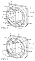
Figure 4 : is a sectional view of the high pressure fuel pump ofFig.1 at TDC; -
Figure 5 : is a sectional view of the high pressure fuel pump during a compression stroke; -
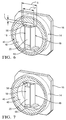
Figure 6 : is a sectional view of the high pressure fuel pump at BDC; and -
Figure 7 : is a sectional view of the high pressure fuel pump during a fill stroke. -
Figure 1 shows a cross section of an embodiment of the present highpressure fuel pump 10 for supplying fuel to a fuel injection system in an internal combustion engine. The pump is used, for example, in a common rail injection system for supplying fuel to the internal combustion engine. - Such a pump typically receives the fuel from the vehicle tank at about 2 to 5 bars and delivers a high pressure of up to 2000 bars and even higher to the common rail of the fuel injection system. The common rail in turn supplies the fuel to the fuel injectors.
- The
pump 10 comprises a housing generally indicated 12, which includes afront cover 14 fixed to aplate 16 also referred to as 'back plate'. Inside the housing 12, apumping unit 18 also referred to as 'pumping head' is fixedly positioned to theback plate 16. Thispumping unit 18 comprises abody 20 having ablind bore 22 therein. Thebody 20 may have an elongate block shape, e.g. parallelepipedic, and may be manufactured in one part with the back plate or is fixed thereto in any appropriate way. Thebore 22 extends from one of the two end faces 24a and 24b of thebody 20. A piston orplunger 26 is reciprocally movable in thebore 22 of the body and has a matching diameter inside the bore. Afront portion 28 of the plunger defines with the bore apressure chamber 30. Theplunger 26 of thepumping unit 18 further comprises afoot portion 32, which may include anend plate 34. - Although not shown in the drawings, the
bore 22 has an inlet for supplying fuel to thepressure chamber 30 and an outlet for delivering pressurized fuel. In fact the inlet provides fuel from the tank to thepressure chamber 30 and the outlet allows delivering fuel under high pressure to the common rail and towards the injectors of the internal combustion engine. Both, the inlet and outlet may be each controlled by a respective valve unit allowing or obturating the flow of fuel therethrough. -
Pump 10 further comprises drive means for drivingplunger 26 by itsfoot portion 32. The drive means comprise acam ring 40 having an innerperipheral surface 42 outlining an inner cam surface. Thecam ring 40 is driven in rotation by adrive shaft 43 that is rotatably mounted in the housing 12. - From
Fig.2 , it can be seen that thepumping unit 18 is positioned so as to be surrounded by thecam ring 40. As will be explained in more detail below, thefoot portion 32 of the plunger is configured to follow thecam surface 42 of the cam ring to cause the reciprocal motion of the latter. - As it will be understood by those skilled in the art, the
cam ring 42 may herein generally take the form of a solid ring having an outerperipheral surface 44 and an innerperipheral surface 42 that are radially separated by the body of the ring. The innerperipheral surface 42 herein forms the desired surface for driving theplunger 26 and is thus designated "inner cam surface". As can be seen inFigs. 1 to 3 , thecam ring 40 is preferably closed on one side by acover plate 44, on the other side of which thedrive shaft 43 is connected. - The
cam ring 40 can be manufactured in any appropriate way. One can e.g. start from a circular solid cylinder or disk and machine therein a circular bore to obtain a ring element. Preferably, as shown inFigs 1 to 3 , the ring element is manufactured from such disk but the circular bore is machined as blind bore, so that thecam ring 40 includes thecover 44. Thedrive shaft 43 may be manufactured in one piece with such cam ring and cover, or simply assembled to the cam ring and cover element. - In the present embodiment, the outer
peripheral surface 44 ofcam ring 40 is a circular surface having a central axis A that defines the revolving axis ofcam ring 40. Thecam surface 42 is a circular surface, the center A' of which is offset with respect to the ring axis A. Theinner cam surface 42 is thus also referred to as eccentric cam. - Turning now again to
Fig.4 , it can be readily seen that thepumping unit 18 is surrounded by thecam ring 40. The pumping unit extends across the cam ring with the end faces 24a, 24b of the pumpingbody 20 facing theinner cam surface 42, and fits inside the cavity defined by the cam ring (appropriate depth is thus required). In use, this cavity is filled with fuel. For this purpose, the a fuel inlet (receiving low pressure fuel from the tank) and a fuel outlet are provided in the back plate, with respective valve means, to control the flow of fuel through the cavity. - It shall be appreciated that the
foot portion 32 of the plunger is arranged to follow theinner cam surface 42 of thecam ring 40 in such a way that the rotation of the cam ring causes theplunger 26 to move axially inbore 22, thereby reciprocally driving the plunger. - This is advantageously achieved in the present embodiment by means of a
spacer element 48, that can also be generally referred to as abutment means, in order to maintain the contact between thefoot portion 32 and the drivinginner cam surface 42. Thespacer element 48 extends in the reciprocating direction of the plunger and has a length selected in such a way that, in any position of the cam ring, a first end of the spacer is in contact with the plunger foot portion, while the opposite second end of the spacer rests against the inner cam surface. But contrary to a conventional spring, the spacer element's length remains substantially constant during operation and is not designed to undergo deformation. - In the shown embodiment, the
spring clip 48 has twolegs 50 united by atransverse bottom section 52. The free ends 54 of the legs form the first end of the spacer, whereas the second end of said spacer is formed by saidbottom section 52. - The spring clip is preferably made of a material with some resilience, typically a metallic material, e.g. steel.
- Although the spring clip is not designed to undergo deformation in use (contrary to the conventional return spring as in
EP 2 093 421 ), it however supports a slight load to prestress theplunger foot portion 32 against itsrespective skid 56. -
Figs. 4 to 7 schematically illustrate thepump 10 in four operational configurations. Thespring clip 48 is used to acts as spacer or stud so that theplunger foot 32 can follow thecam surface 42. When theeccentric cam surface 42 rotates, the distance between thecam surface 42 andtop body surface 24a changes.Spring clip 48 ensures contact between thefoot portion 32 andcam surface 42, causing theplunger 26 to reciprocate inbore 22. - It may be noticed that
spring clip 48 is movable in the reciprocating direction ofplunger 26 and actually is preferably designed to have itsbranches 48 slide along the outer flat sides ofbody block 20, aligning theclip 48 in its sliding direction. - It may be further noticed that the
spring clip 48 rests at both ends onto thecam surface 42 viarespective skid elements 56. Theskids 56 are configured as interface elements that aid to convert the circular motion of theeccentric cam surface 42 into a linear motion. Theskid element 56 here takes the form of a rectangular pad having acurved side 58 in contact with the cam surface and an oppositeflat side 60 against which theplunger foot portion 34, , respectively the clip bottom, rests. Hence, theplunger 26 andspring clip 48 technically rest indirectly againstcam surface 42 via therespective skid elements 56. - The
curved surface 58 of theskid 56 has a curvature radius preferably matching that of thecam surface 42. The dimensions of theflat side 60 are chosen to maintain contact with thefoot portion 34 as the skid moves transversely with respect to thespring clip 48, as will be explained below. Since the inner cavity of thecam ring 40 is filled with fuel, a film of fuel exists between the skid'scurved surface 48 and theinner cam surface 42, facilitating the sliding. - The operation of the
pump 10 will now be explained with reference toFigs. 4 to 7 . Starting withFig.4 , theplunger 26 is at the top-most position (TDC) in thechamber 30. The thicker part of theeccentric cam 40 is located below the pumping body, thebottom face 24b thereof being very close to the skid; whereas the thinner part of thecam ring 40 is above theplunger foot portion 32. This position corresponds to the end of the filling stroke, thepressure chamber 30 has its largest volume and is filled with fuel. - As the cam ring rotates (counter clockwise with respect to the Figs.), the thicker part of
cam ring 40 moves to the side and the cam ring portion above thefoot portion 32 becomes thicker. This causes theplunger 26 to move into thebore 22 of pumping body 20: this is the pumping stroke. - In the configuration of
Fig. 6 the cam ring's 20 thicker portion is above thefoot portion 32 and the plunger is fully into thebore 22. This corresponds to the bottom dead center (BDC). Shortly before reaching that position, the outlet valve has been opened to evacuate the pressurized fuel. In the BDC the chamber is thus empty. - Further rotation of the
cam ring 40 from the BDC gradually reduces the thickness above thefoot portion 32, operating a new pumping stroke, as can be understood fromFig.7 . Hence, a full cycle of thepump 10 is achieved through a single rotation of thecam ring 40. - Turning back to
Fig.4 , it may be observed that in this configuration, thefoot portion 32 andspring clip base 52 are centered on theirrespective skids 56. Here, the rotation axis of the cam ring A and center A' of theeccentric cam surface 42 are vertically aligned (with reference to the figure). When thecam ring 40 makes one rotation, the center A' of thecircular cam surface 42 rotates around the fixed center A of thecam ring 40. Due to the eccentricity, and since theskids 56 are maintained at diametrically opposite position by the fixedlength clip 48, theskids 56 need to move to follow the curvature of theinner cam surface 42. Since the pumpingbody 20 is fixed and theclip 48 can only move in the plunger's reciprocating direction, the width of the skidflat surface 60 needs to be designed to allow relative displacement of the plungerflat end 34, respectivelyclip base 52. - Some preferred operational details may be described for the sake of completion. The rotation axis A of the cam ring (center of outer peripheral surface 44) preferably crosses the central axis B of the bore 22 (defining the plunger's reciprocating axis). In the TBC and TDC configuration, the rotation axis A and the cam center A' are aligned on the central axis B. The distance A-A' is the maximum stroke of the pumping unit. In practice, the offset distance A-A' may be selected in the range of 2 to 6 mm.
- Also, the length LS (
Fig.6 ) of theflat side 60 of theskid 56 should be at least equal to the length of the flat side LF plus twice the offset distance A-A'. - From the above, it will further appear that the height of the
spring clip 48 corresponds to the diameter of theinner cam 42 minus the thickness t (Fig.6 ) of the two skids 56. Since the skids are able to move relative to thespring clip 48, thespring clip 48 keeps its length. - As it may be noticed from
Fig.1 , thecover 14 comprises acylindrical section 141 surrounding thecam ring 40 and afront plate 142 axially blocking thecam ring 40. The inner diameter ofcylindrical section 141 is adapted to serve as bearing to rotatably accommodatedcam ring 40.Front plate 141 has acentral opening 143 for thedrive shaft 43. If desirable, thiscentral opening 143 may further be shaped as a bearing section to assist in the rotation of thedrive shaft 43 and particularly take up load applied on the external portion of thedrive shaft 43, e.g. by a driving belt. - The above embodiment is only one possible embodiment of the present invention and has been given for illustration purposes. The actual shape of the various components may differ from what has been presented.
- In particular, while in the above embodiment a U-shaped spring clip is used as abutment means, those skilled on the art may devise other designs for the abutment means. For example, the inner cam surface could comprise a groove and the plunger foot portion could be engaged partially in such groove by a terminal extension that is blocked in radial direction.
- Another way to explore may be to vary the shape of the inner cam surface, e.g. in order to perform more than one couple of in and out strokes per cam ring revolution.
- Still in a further embodiment, a couple of pumping units could be arranged in the cavity of the
cam ring 40. The two plungers could be made axially integral in movement, whereby only one abutment means/spring clip may be used. The two pumping units could also be arranged in an axially inverted fashion (one plunger upwards, the other downwards). In such case, the abutment means may simply consist in a blocking link that makes the two plungers axially locked.
Claims (7)
- A high pressure fuel pump for an internal combustion engine comprising:a pumping unit (18) comprising a body (20) with a bore (22) therein and a plunger (26) reciprocally movable in said bore, said plunger having a front portion defining, with said bore, a pressure chamber (30) in said bore and an opposite foot portion (32);drive means for driving said plunger by its foot portion;characterized in thatsaid drive means comprise a cam ring (40) arranged to be rotatable about an axis (A), said cam ring having an inner cam surface (42);said pumping unit (18) is positioned so as to be surrounded by said cam ring (40) with said plunger foot portion (32) arranged to follow said inner cam surface (42) of said cam ring (40) in such a way that the rotation of said cam ring causes said plunger to reciprocate in said bore (22); comprising abutment means configured to maintain the foot portion (32) of said plunger (26) in driving engagement with said inner cam surface (42),wherein said abutment means comprise a spacer element (48) extending in the reciprocating direction of said plunger having a length selected in such a way that, in any position of the cam ring, a first end of said spacer is in contact with said foot portion of said plunger,wherein said plunger foot portion (32) rests against said inner cam surface via a skid (56) element, said foot potion being pressed against said skid by the first end of said spacer element; and the second end of said spacer element (48) rests against said inner cam surface via another skid element (56).The pump according to claim 1, wherein said inner cam surface (42) is a circular surface having a center axis (A') offset with regard to said rotation axis (A) of said cam ring (40).
- The pump according to claim 1, wherein said spacer element (48) is axially moveable in the reciprocating direction of said plunger.
- The pump according to claim 1, wherein said skids are configured as rectangular pads having a curved side in contact with the cam surface and an opposite flat side.
- The pump according to claim 1 to 4, wherein
said pumping unit body (20) has an elongate shape in the reciprocating direction of said plunger (26);
said spacer element (48) is a U-shaped element having two legs (50) united by a transverse bottom section (52), the outer ends of said legs forming the first end of said spacer element, whereas the second end of said spacer element is formed by said bottom section;
said legs (50) of said spacer element are placed on both sides of said body for its axial guiding. - The pump according to any one of claims 1 to 5 , wherein said spacer element is made from a resilient material, preferably metallic, in particular steel, to provide a pre-loading force.
- The pump according to any one of the preceding claims, comprising a housing with a backplate on which said body is fixedly arranged and a cover having an inner cylindrical cavity accommodating the revolving cam ring.
- The pump according to any one of the preceding claims, wherein said cam ring (40) is rotationally driven by a revolving drive shaft (43), said drive shaft being integral with said cam ring or rotationally coupled thereto.
Applications Claiming Priority (1)
| Application Number | Priority Date | Filing Date | Title |
|---|---|---|---|
| GBGB1507704.3A GB201507704D0 (en) | 2015-05-06 | 2015-05-06 | High-pressure fuel pump |
Publications (2)
| Publication Number | Publication Date |
|---|---|
| EP3091220A1 true EP3091220A1 (en) | 2016-11-09 |
| EP3091220B1 EP3091220B1 (en) | 2018-10-17 |
Family
ID=53489175
Family Applications (1)
| Application Number | Title | Priority Date | Filing Date |
|---|---|---|---|
| EP16168225.7A Active EP3091220B1 (en) | 2015-05-06 | 2016-05-04 | High-pressure fuel pump |
Country Status (2)
| Country | Link |
|---|---|
| EP (1) | EP3091220B1 (en) |
| GB (1) | GB201507704D0 (en) |
Cited By (1)
| Publication number | Priority date | Publication date | Assignee | Title |
|---|---|---|---|---|
| US12203457B2 (en) | 2021-07-14 | 2025-01-21 | Cummins-Scania Hpcr System, Llc | Fuel pump assembly |
Citations (3)
| Publication number | Priority date | Publication date | Assignee | Title |
|---|---|---|---|---|
| US4108130A (en) * | 1977-05-18 | 1978-08-22 | Caterpillar Tractor Co. | Fuel injection pump |
| WO1999036686A1 (en) * | 1998-01-15 | 1999-07-22 | Stanadyne Automotive Corp. | Hydraulic pump with engine mounted drive bearing |
| CN101270715A (en) * | 2008-04-30 | 2008-09-24 | 福建省莆田市中涵机动力有限公司 | Fuel feed pump of diesel engine high-pressure co-rail fuel oil system |
-
2015
- 2015-05-06 GB GBGB1507704.3A patent/GB201507704D0/en not_active Ceased
-
2016
- 2016-05-04 EP EP16168225.7A patent/EP3091220B1/en active Active
Patent Citations (3)
| Publication number | Priority date | Publication date | Assignee | Title |
|---|---|---|---|---|
| US4108130A (en) * | 1977-05-18 | 1978-08-22 | Caterpillar Tractor Co. | Fuel injection pump |
| WO1999036686A1 (en) * | 1998-01-15 | 1999-07-22 | Stanadyne Automotive Corp. | Hydraulic pump with engine mounted drive bearing |
| CN101270715A (en) * | 2008-04-30 | 2008-09-24 | 福建省莆田市中涵机动力有限公司 | Fuel feed pump of diesel engine high-pressure co-rail fuel oil system |
Cited By (1)
| Publication number | Priority date | Publication date | Assignee | Title |
|---|---|---|---|---|
| US12203457B2 (en) | 2021-07-14 | 2025-01-21 | Cummins-Scania Hpcr System, Llc | Fuel pump assembly |
Also Published As
| Publication number | Publication date |
|---|---|
| EP3091220B1 (en) | 2018-10-17 |
| GB201507704D0 (en) | 2015-06-17 |
Similar Documents
| Publication | Publication Date | Title |
|---|---|---|
| CN101523044A (en) | Tappet assembly for a high-pressure pump and high-pressure pump comprising at least one tappet assembly | |
| US6250893B1 (en) | Radial piston pump for feeding high-pressure fuel supply | |
| JP5187254B2 (en) | High pressure pump | |
| JP3852756B2 (en) | Fuel injection pump | |
| US9702329B2 (en) | Pump and common rail fuel injection system | |
| JP2002509223A (en) | Radial piston pump for high pressure fuel supply | |
| JP2004537005A (en) | High pressure supply pump | |
| JP5472340B2 (en) | Fuel supply pump | |
| US8337178B2 (en) | Pump, particularly high-pressure fuel pump | |
| CN110945241B (en) | Piston pump, in particular high-pressure fuel pump for an internal combustion engine | |
| US5375982A (en) | Radial pump | |
| CN111636988B (en) | Fuel injection pump | |
| EP3091220B1 (en) | High-pressure fuel pump | |
| EP3816445B1 (en) | Automatic bidirectional valve and pump provided with said valve | |
| US20250154941A1 (en) | Fuel pump assembly | |
| EP2189658B1 (en) | Fluid Pump Assembly | |
| WO2003078822A1 (en) | Pump components and method | |
| WO2022108578A1 (en) | Fuel pump assembly | |
| WO2016117297A1 (en) | High-pressure pump and method for manufacturing same | |
| US20040213689A1 (en) | Fuel injection pump and rotation-linear motion transforming mechanism with safeguard | |
| EP4118315B1 (en) | Compact opposed pump | |
| JP6579943B2 (en) | Fuel supply pump | |
| JP6451393B2 (en) | pump | |
| US10690098B2 (en) | High-pressure pump | |
| US9140244B2 (en) | Piston pump with cam actuated valves |
Legal Events
| Date | Code | Title | Description |
|---|---|---|---|
| PUAI | Public reference made under article 153(3) epc to a published international application that has entered the european phase |
Free format text: ORIGINAL CODE: 0009012 |
|
| AK | Designated contracting states |
Kind code of ref document: A1 Designated state(s): AL AT BE BG CH CY CZ DE DK EE ES FI FR GB GR HR HU IE IS IT LI LT LU LV MC MK MT NL NO PL PT RO RS SE SI SK SM TR |
|
| AX | Request for extension of the european patent |
Extension state: BA ME |
|
| STAA | Information on the status of an ep patent application or granted ep patent |
Free format text: STATUS: REQUEST FOR EXAMINATION WAS MADE |
|
| 17P | Request for examination filed |
Effective date: 20170509 |
|
| RBV | Designated contracting states (corrected) |
Designated state(s): AL AT BE BG CH CY CZ DE DK EE ES FI FR GB GR HR HU IE IS IT LI LT LU LV MC MK MT NL NO PL PT RO RS SE SI SK SM TR |
|
| GRAP | Despatch of communication of intention to grant a patent |
Free format text: ORIGINAL CODE: EPIDOSNIGR1 |
|
| STAA | Information on the status of an ep patent application or granted ep patent |
Free format text: STATUS: GRANT OF PATENT IS INTENDED |
|
| INTG | Intention to grant announced |
Effective date: 20180522 |
|
| GRAS | Grant fee paid |
Free format text: ORIGINAL CODE: EPIDOSNIGR3 |
|
| GRAA | (expected) grant |
Free format text: ORIGINAL CODE: 0009210 |
|
| STAA | Information on the status of an ep patent application or granted ep patent |
Free format text: STATUS: THE PATENT HAS BEEN GRANTED |
|
| AK | Designated contracting states |
Kind code of ref document: B1 Designated state(s): AL AT BE BG CH CY CZ DE DK EE ES FI FR GB GR HR HU IE IS IT LI LT LU LV MC MK MT NL NO PL PT RO RS SE SI SK SM TR |
|
| REG | Reference to a national code |
Ref country code: GB Ref legal event code: FG4D |
|
| REG | Reference to a national code |
Ref country code: CH Ref legal event code: EP |
|
| REG | Reference to a national code |
Ref country code: IE Ref legal event code: FG4D |
|
| REG | Reference to a national code |
Ref country code: DE Ref legal event code: R096 Ref document number: 602016006370 Country of ref document: DE Ref country code: AT Ref legal event code: REF Ref document number: 1054332 Country of ref document: AT Kind code of ref document: T Effective date: 20181115 |
|
| REG | Reference to a national code |
Ref country code: NL Ref legal event code: MP Effective date: 20181017 Ref country code: DE Ref legal event code: R081 Ref document number: 602016006370 Country of ref document: DE Owner name: DELPHI TECHNOLOGIES IP LIMITED, BB Free format text: FORMER OWNER: DELPHI INTERNATIONAL OPERATIONS LUXEMBOURG S.A R.L., BASCHARAGE, LU |
|
| REG | Reference to a national code |
Ref country code: LT Ref legal event code: MG4D |
|
| REG | Reference to a national code |
Ref country code: AT Ref legal event code: MK05 Ref document number: 1054332 Country of ref document: AT Kind code of ref document: T Effective date: 20181017 |
|
| REG | Reference to a national code |
Ref country code: GB Ref legal event code: 732E Free format text: REGISTERED BETWEEN 20190222 AND 20190227 |
|
| PG25 | Lapsed in a contracting state [announced via postgrant information from national office to epo] |
Ref country code: NL Free format text: LAPSE BECAUSE OF FAILURE TO SUBMIT A TRANSLATION OF THE DESCRIPTION OR TO PAY THE FEE WITHIN THE PRESCRIBED TIME-LIMIT Effective date: 20181017 |
|
| PG25 | Lapsed in a contracting state [announced via postgrant information from national office to epo] |
Ref country code: IS Free format text: LAPSE BECAUSE OF FAILURE TO SUBMIT A TRANSLATION OF THE DESCRIPTION OR TO PAY THE FEE WITHIN THE PRESCRIBED TIME-LIMIT Effective date: 20190217 Ref country code: ES Free format text: LAPSE BECAUSE OF FAILURE TO SUBMIT A TRANSLATION OF THE DESCRIPTION OR TO PAY THE FEE WITHIN THE PRESCRIBED TIME-LIMIT Effective date: 20181017 Ref country code: LT Free format text: LAPSE BECAUSE OF FAILURE TO SUBMIT A TRANSLATION OF THE DESCRIPTION OR TO PAY THE FEE WITHIN THE PRESCRIBED TIME-LIMIT Effective date: 20181017 Ref country code: NO Free format text: LAPSE BECAUSE OF FAILURE TO SUBMIT A TRANSLATION OF THE DESCRIPTION OR TO PAY THE FEE WITHIN THE PRESCRIBED TIME-LIMIT Effective date: 20190117 Ref country code: BG Free format text: LAPSE BECAUSE OF FAILURE TO SUBMIT A TRANSLATION OF THE DESCRIPTION OR TO PAY THE FEE WITHIN THE PRESCRIBED TIME-LIMIT Effective date: 20190117 Ref country code: PL Free format text: LAPSE BECAUSE OF FAILURE TO SUBMIT A TRANSLATION OF THE DESCRIPTION OR TO PAY THE FEE WITHIN THE PRESCRIBED TIME-LIMIT Effective date: 20181017 Ref country code: HR Free format text: LAPSE BECAUSE OF FAILURE TO SUBMIT A TRANSLATION OF THE DESCRIPTION OR TO PAY THE FEE WITHIN THE PRESCRIBED TIME-LIMIT Effective date: 20181017 Ref country code: AT Free format text: LAPSE BECAUSE OF FAILURE TO SUBMIT A TRANSLATION OF THE DESCRIPTION OR TO PAY THE FEE WITHIN THE PRESCRIBED TIME-LIMIT Effective date: 20181017 Ref country code: LV Free format text: LAPSE BECAUSE OF FAILURE TO SUBMIT A TRANSLATION OF THE DESCRIPTION OR TO PAY THE FEE WITHIN THE PRESCRIBED TIME-LIMIT Effective date: 20181017 Ref country code: FI Free format text: LAPSE BECAUSE OF FAILURE TO SUBMIT A TRANSLATION OF THE DESCRIPTION OR TO PAY THE FEE WITHIN THE PRESCRIBED TIME-LIMIT Effective date: 20181017 |
|
| PG25 | Lapsed in a contracting state [announced via postgrant information from national office to epo] |
Ref country code: SE Free format text: LAPSE BECAUSE OF FAILURE TO SUBMIT A TRANSLATION OF THE DESCRIPTION OR TO PAY THE FEE WITHIN THE PRESCRIBED TIME-LIMIT Effective date: 20181017 Ref country code: AL Free format text: LAPSE BECAUSE OF FAILURE TO SUBMIT A TRANSLATION OF THE DESCRIPTION OR TO PAY THE FEE WITHIN THE PRESCRIBED TIME-LIMIT Effective date: 20181017 Ref country code: RS Free format text: LAPSE BECAUSE OF FAILURE TO SUBMIT A TRANSLATION OF THE DESCRIPTION OR TO PAY THE FEE WITHIN THE PRESCRIBED TIME-LIMIT Effective date: 20181017 Ref country code: GR Free format text: LAPSE BECAUSE OF FAILURE TO SUBMIT A TRANSLATION OF THE DESCRIPTION OR TO PAY THE FEE WITHIN THE PRESCRIBED TIME-LIMIT Effective date: 20190118 Ref country code: PT Free format text: LAPSE BECAUSE OF FAILURE TO SUBMIT A TRANSLATION OF THE DESCRIPTION OR TO PAY THE FEE WITHIN THE PRESCRIBED TIME-LIMIT Effective date: 20190217 |
|
| REG | Reference to a national code |
Ref country code: DE Ref legal event code: R097 Ref document number: 602016006370 Country of ref document: DE |
|
| PG25 | Lapsed in a contracting state [announced via postgrant information from national office to epo] |
Ref country code: IT Free format text: LAPSE BECAUSE OF FAILURE TO SUBMIT A TRANSLATION OF THE DESCRIPTION OR TO PAY THE FEE WITHIN THE PRESCRIBED TIME-LIMIT Effective date: 20181017 Ref country code: DK Free format text: LAPSE BECAUSE OF FAILURE TO SUBMIT A TRANSLATION OF THE DESCRIPTION OR TO PAY THE FEE WITHIN THE PRESCRIBED TIME-LIMIT Effective date: 20181017 Ref country code: CZ Free format text: LAPSE BECAUSE OF FAILURE TO SUBMIT A TRANSLATION OF THE DESCRIPTION OR TO PAY THE FEE WITHIN THE PRESCRIBED TIME-LIMIT Effective date: 20181017 |
|
| PLBE | No opposition filed within time limit |
Free format text: ORIGINAL CODE: 0009261 |
|
| STAA | Information on the status of an ep patent application or granted ep patent |
Free format text: STATUS: NO OPPOSITION FILED WITHIN TIME LIMIT |
|
| PG25 | Lapsed in a contracting state [announced via postgrant information from national office to epo] |
Ref country code: SM Free format text: LAPSE BECAUSE OF FAILURE TO SUBMIT A TRANSLATION OF THE DESCRIPTION OR TO PAY THE FEE WITHIN THE PRESCRIBED TIME-LIMIT Effective date: 20181017 Ref country code: EE Free format text: LAPSE BECAUSE OF FAILURE TO SUBMIT A TRANSLATION OF THE DESCRIPTION OR TO PAY THE FEE WITHIN THE PRESCRIBED TIME-LIMIT Effective date: 20181017 Ref country code: SK Free format text: LAPSE BECAUSE OF FAILURE TO SUBMIT A TRANSLATION OF THE DESCRIPTION OR TO PAY THE FEE WITHIN THE PRESCRIBED TIME-LIMIT Effective date: 20181017 Ref country code: RO Free format text: LAPSE BECAUSE OF FAILURE TO SUBMIT A TRANSLATION OF THE DESCRIPTION OR TO PAY THE FEE WITHIN THE PRESCRIBED TIME-LIMIT Effective date: 20181017 |
|
| 26N | No opposition filed |
Effective date: 20190718 |
|
| PG25 | Lapsed in a contracting state [announced via postgrant information from national office to epo] |
Ref country code: SI Free format text: LAPSE BECAUSE OF FAILURE TO SUBMIT A TRANSLATION OF THE DESCRIPTION OR TO PAY THE FEE WITHIN THE PRESCRIBED TIME-LIMIT Effective date: 20181017 |
|
| REG | Reference to a national code |
Ref country code: CH Ref legal event code: PL |
|
| PG25 | Lapsed in a contracting state [announced via postgrant information from national office to epo] |
Ref country code: CH Free format text: LAPSE BECAUSE OF NON-PAYMENT OF DUE FEES Effective date: 20190531 Ref country code: LI Free format text: LAPSE BECAUSE OF NON-PAYMENT OF DUE FEES Effective date: 20190531 Ref country code: MC Free format text: LAPSE BECAUSE OF FAILURE TO SUBMIT A TRANSLATION OF THE DESCRIPTION OR TO PAY THE FEE WITHIN THE PRESCRIBED TIME-LIMIT Effective date: 20181017 |
|
| REG | Reference to a national code |
Ref country code: BE Ref legal event code: MM Effective date: 20190531 |
|
| PG25 | Lapsed in a contracting state [announced via postgrant information from national office to epo] |
Ref country code: LU Free format text: LAPSE BECAUSE OF NON-PAYMENT OF DUE FEES Effective date: 20190504 |
|
| PG25 | Lapsed in a contracting state [announced via postgrant information from national office to epo] |
Ref country code: TR Free format text: LAPSE BECAUSE OF FAILURE TO SUBMIT A TRANSLATION OF THE DESCRIPTION OR TO PAY THE FEE WITHIN THE PRESCRIBED TIME-LIMIT Effective date: 20181017 |
|
| PG25 | Lapsed in a contracting state [announced via postgrant information from national office to epo] |
Ref country code: IE Free format text: LAPSE BECAUSE OF NON-PAYMENT OF DUE FEES Effective date: 20190504 |
|
| PG25 | Lapsed in a contracting state [announced via postgrant information from national office to epo] |
Ref country code: BE Free format text: LAPSE BECAUSE OF NON-PAYMENT OF DUE FEES Effective date: 20190531 |
|
| PG25 | Lapsed in a contracting state [announced via postgrant information from national office to epo] |
Ref country code: CY Free format text: LAPSE BECAUSE OF FAILURE TO SUBMIT A TRANSLATION OF THE DESCRIPTION OR TO PAY THE FEE WITHIN THE PRESCRIBED TIME-LIMIT Effective date: 20181017 |
|
| PG25 | Lapsed in a contracting state [announced via postgrant information from national office to epo] |
Ref country code: HU Free format text: LAPSE BECAUSE OF FAILURE TO SUBMIT A TRANSLATION OF THE DESCRIPTION OR TO PAY THE FEE WITHIN THE PRESCRIBED TIME-LIMIT; INVALID AB INITIO Effective date: 20160504 Ref country code: MT Free format text: LAPSE BECAUSE OF FAILURE TO SUBMIT A TRANSLATION OF THE DESCRIPTION OR TO PAY THE FEE WITHIN THE PRESCRIBED TIME-LIMIT Effective date: 20181017 |
|
| PG25 | Lapsed in a contracting state [announced via postgrant information from national office to epo] |
Ref country code: MK Free format text: LAPSE BECAUSE OF FAILURE TO SUBMIT A TRANSLATION OF THE DESCRIPTION OR TO PAY THE FEE WITHIN THE PRESCRIBED TIME-LIMIT Effective date: 20181017 |
|
| REG | Reference to a national code |
Ref country code: FR Ref legal event code: PLFP Year of fee payment: 8 |
|
| P01 | Opt-out of the competence of the unified patent court (upc) registered |
Effective date: 20230327 |
|
| REG | Reference to a national code |
Ref country code: DE Ref legal event code: R081 Ref document number: 602016006370 Country of ref document: DE Owner name: PHINIA DELPHI LUXEMBOURG SARL, LU Free format text: FORMER OWNER: DELPHI TECHNOLOGIES IP LIMITED, ST. MICHAEL, BB |
|
| PGFP | Annual fee paid to national office [announced via postgrant information from national office to epo] |
Ref country code: DE Payment date: 20250409 Year of fee payment: 10 |
|
| PGFP | Annual fee paid to national office [announced via postgrant information from national office to epo] |
Ref country code: FR Payment date: 20250409 Year of fee payment: 10 |
|
| PGFP | Annual fee paid to national office [announced via postgrant information from national office to epo] |
Ref country code: GB Payment date: 20260320 Year of fee payment: 11 |