EP3091216A1 - Liner for a gas turbine engine - Google Patents
Liner for a gas turbine engine Download PDFInfo
- Publication number
- EP3091216A1 EP3091216A1 EP16168799.1A EP16168799A EP3091216A1 EP 3091216 A1 EP3091216 A1 EP 3091216A1 EP 16168799 A EP16168799 A EP 16168799A EP 3091216 A1 EP3091216 A1 EP 3091216A1
- Authority
- EP
- European Patent Office
- Prior art keywords
- liner
- inner diameter
- guide vane
- outer diameter
- structural guide
- Prior art date
- Legal status (The legal status is an assumption and is not a legal conclusion. Google has not performed a legal analysis and makes no representation as to the accuracy of the status listed.)
- Granted
Links
Images

Classifications
-
- F—MECHANICAL ENGINEERING; LIGHTING; HEATING; WEAPONS; BLASTING
- F04—POSITIVE - DISPLACEMENT MACHINES FOR LIQUIDS; PUMPS FOR LIQUIDS OR ELASTIC FLUIDS
- F04D—NON-POSITIVE-DISPLACEMENT PUMPS
- F04D29/00—Details, component parts, or accessories
- F04D29/66—Combating cavitation, whirls, noise, vibration or the like; Balancing
- F04D29/661—Combating cavitation, whirls, noise, vibration or the like; Balancing especially adapted for elastic fluid pumps
- F04D29/668—Combating cavitation, whirls, noise, vibration or the like; Balancing especially adapted for elastic fluid pumps damping or preventing mechanical vibrations
-
- F—MECHANICAL ENGINEERING; LIGHTING; HEATING; WEAPONS; BLASTING
- F01—MACHINES OR ENGINES IN GENERAL; ENGINE PLANTS IN GENERAL; STEAM ENGINES
- F01D—NON-POSITIVE DISPLACEMENT MACHINES OR ENGINES, e.g. STEAM TURBINES
- F01D25/00—Component parts, details, or accessories, not provided for in, or of interest apart from, other groups
- F01D25/04—Antivibration arrangements
-
- F—MECHANICAL ENGINEERING; LIGHTING; HEATING; WEAPONS; BLASTING
- F01—MACHINES OR ENGINES IN GENERAL; ENGINE PLANTS IN GENERAL; STEAM ENGINES
- F01D—NON-POSITIVE DISPLACEMENT MACHINES OR ENGINES, e.g. STEAM TURBINES
- F01D25/00—Component parts, details, or accessories, not provided for in, or of interest apart from, other groups
- F01D25/16—Arrangement of bearings; Supporting or mounting bearings in casings
- F01D25/162—Bearing supports
-
- F—MECHANICAL ENGINEERING; LIGHTING; HEATING; WEAPONS; BLASTING
- F02—COMBUSTION ENGINES; HOT-GAS OR COMBUSTION-PRODUCT ENGINE PLANTS
- F02C—GAS-TURBINE PLANTS; AIR INTAKES FOR JET-PROPULSION PLANTS; CONTROLLING FUEL SUPPLY IN AIR-BREATHING JET-PROPULSION PLANTS
- F02C7/00—Features, components parts, details or accessories, not provided for in, or of interest apart form groups F02C1/00 - F02C6/00; Air intakes for jet-propulsion plants
- F02C7/04—Air intakes for gas-turbine plants or jet-propulsion plants
- F02C7/045—Air intakes for gas-turbine plants or jet-propulsion plants having provisions for noise suppression
-
- F—MECHANICAL ENGINEERING; LIGHTING; HEATING; WEAPONS; BLASTING
- F02—COMBUSTION ENGINES; HOT-GAS OR COMBUSTION-PRODUCT ENGINE PLANTS
- F02K—JET-PROPULSION PLANTS
- F02K1/00—Plants characterised by the form or arrangement of the jet pipe or nozzle; Jet pipes or nozzles peculiar thereto
- F02K1/06—Varying effective area of jet pipe or nozzle
- F02K1/08—Varying effective area of jet pipe or nozzle by axially moving or transversely deforming an internal member, e.g. the exhaust cone
-
- F—MECHANICAL ENGINEERING; LIGHTING; HEATING; WEAPONS; BLASTING
- F02—COMBUSTION ENGINES; HOT-GAS OR COMBUSTION-PRODUCT ENGINE PLANTS
- F02K—JET-PROPULSION PLANTS
- F02K1/00—Plants characterised by the form or arrangement of the jet pipe or nozzle; Jet pipes or nozzles peculiar thereto
- F02K1/78—Other construction of jet pipes
- F02K1/82—Jet pipe walls, e.g. liners
- F02K1/827—Sound absorbing structures or liners
-
- F—MECHANICAL ENGINEERING; LIGHTING; HEATING; WEAPONS; BLASTING
- F02—COMBUSTION ENGINES; HOT-GAS OR COMBUSTION-PRODUCT ENGINE PLANTS
- F02K—JET-PROPULSION PLANTS
- F02K3/00—Plants including a gas turbine driving a compressor or a ducted fan
- F02K3/02—Plants including a gas turbine driving a compressor or a ducted fan in which part of the working fluid by-passes the turbine and combustion chamber
- F02K3/04—Plants including a gas turbine driving a compressor or a ducted fan in which part of the working fluid by-passes the turbine and combustion chamber the plant including ducted fans, i.e. fans with high volume, low pressure outputs, for augmenting the jet thrust, e.g. of double-flow type
- F02K3/06—Plants including a gas turbine driving a compressor or a ducted fan in which part of the working fluid by-passes the turbine and combustion chamber the plant including ducted fans, i.e. fans with high volume, low pressure outputs, for augmenting the jet thrust, e.g. of double-flow type with front fan
-
- F—MECHANICAL ENGINEERING; LIGHTING; HEATING; WEAPONS; BLASTING
- F04—POSITIVE - DISPLACEMENT MACHINES FOR LIQUIDS; PUMPS FOR LIQUIDS OR ELASTIC FLUIDS
- F04D—NON-POSITIVE-DISPLACEMENT PUMPS
- F04D29/00—Details, component parts, or accessories
- F04D29/40—Casings; Connections of working fluid
- F04D29/52—Casings; Connections of working fluid for axial pumps
- F04D29/522—Casings; Connections of working fluid for axial pumps especially adapted for elastic fluid pumps
- F04D29/526—Details of the casing section radially opposing blade tips
-
- F—MECHANICAL ENGINEERING; LIGHTING; HEATING; WEAPONS; BLASTING
- F04—POSITIVE - DISPLACEMENT MACHINES FOR LIQUIDS; PUMPS FOR LIQUIDS OR ELASTIC FLUIDS
- F04D—NON-POSITIVE-DISPLACEMENT PUMPS
- F04D29/00—Details, component parts, or accessories
- F04D29/40—Casings; Connections of working fluid
- F04D29/52—Casings; Connections of working fluid for axial pumps
- F04D29/54—Fluid-guiding means, e.g. diffusers
- F04D29/541—Specially adapted for elastic fluid pumps
-
- F—MECHANICAL ENGINEERING; LIGHTING; HEATING; WEAPONS; BLASTING
- F05—INDEXING SCHEMES RELATING TO ENGINES OR PUMPS IN VARIOUS SUBCLASSES OF CLASSES F01-F04
- F05D—INDEXING SCHEME FOR ASPECTS RELATING TO NON-POSITIVE-DISPLACEMENT MACHINES OR ENGINES, GAS-TURBINES OR JET-PROPULSION PLANTS
- F05D2220/00—Application
- F05D2220/30—Application in turbines
- F05D2220/36—Application in turbines specially adapted for the fan of turbofan engines
-
- F—MECHANICAL ENGINEERING; LIGHTING; HEATING; WEAPONS; BLASTING
- F05—INDEXING SCHEMES RELATING TO ENGINES OR PUMPS IN VARIOUS SUBCLASSES OF CLASSES F01-F04
- F05D—INDEXING SCHEME FOR ASPECTS RELATING TO NON-POSITIVE-DISPLACEMENT MACHINES OR ENGINES, GAS-TURBINES OR JET-PROPULSION PLANTS
- F05D2240/00—Components
- F05D2240/10—Stators
- F05D2240/12—Fluid guiding means, e.g. vanes
-
- F—MECHANICAL ENGINEERING; LIGHTING; HEATING; WEAPONS; BLASTING
- F05—INDEXING SCHEMES RELATING TO ENGINES OR PUMPS IN VARIOUS SUBCLASSES OF CLASSES F01-F04
- F05D—INDEXING SCHEME FOR ASPECTS RELATING TO NON-POSITIVE-DISPLACEMENT MACHINES OR ENGINES, GAS-TURBINES OR JET-PROPULSION PLANTS
- F05D2250/00—Geometry
- F05D2250/20—Three-dimensional
- F05D2250/28—Three-dimensional patterned
- F05D2250/283—Three-dimensional patterned honeycomb
-
- F—MECHANICAL ENGINEERING; LIGHTING; HEATING; WEAPONS; BLASTING
- F05—INDEXING SCHEMES RELATING TO ENGINES OR PUMPS IN VARIOUS SUBCLASSES OF CLASSES F01-F04
- F05D—INDEXING SCHEME FOR ASPECTS RELATING TO NON-POSITIVE-DISPLACEMENT MACHINES OR ENGINES, GAS-TURBINES OR JET-PROPULSION PLANTS
- F05D2260/00—Function
- F05D2260/96—Preventing, counteracting or reducing vibration or noise
-
- F—MECHANICAL ENGINEERING; LIGHTING; HEATING; WEAPONS; BLASTING
- F05—INDEXING SCHEMES RELATING TO ENGINES OR PUMPS IN VARIOUS SUBCLASSES OF CLASSES F01-F04
- F05D—INDEXING SCHEME FOR ASPECTS RELATING TO NON-POSITIVE-DISPLACEMENT MACHINES OR ENGINES, GAS-TURBINES OR JET-PROPULSION PLANTS
- F05D2260/00—Function
- F05D2260/96—Preventing, counteracting or reducing vibration or noise
- F05D2260/963—Preventing, counteracting or reducing vibration or noise by Helmholtz resonators
Definitions
- a vibratory stress allowance of the structural guide vane is limited to a percentage of the structural guide vane's Goodman capability, wherein the Goodman capability is a maximum amount of vibratory stress that the structural guide vane can withstand before cracking. Reducing vibratory stresses to meet the Goodman capability is technically challenging and is typically accomplished by making changes to the airfoil part, the airfoil material properties, the steady stress of the airfoil, or by modifying the source of the vibration.
- Liners are currently used in the engine or the nacelle of the engine to reduce the fan module noise. As such the liner is designed to reduce noise. Particularly, the liner is designed to attenuate frequencies over 1,000 Hertz.
- the structural guide vane includes a leading edge and a trailing edge.
- the liner is positioned along the outer diameter between the aft end of the fan case and a leading edge of the structural guide vane.
- the structural guide vane includes a leading edge and a trailing edge.
- the liner is positioned along the outer diameter between the trailing edge of the structural guide vane and the translating sleeve.
- the structural guide vane defines an inner diameter vane passage and an outer diameter vane passage.
- the method further includes positioning the liner along the outer diameter in the outer diameter vane passage.
- a system having a flow channel including an inner diameter and an outer diameter.
- a structural guide vane extends between the inner diameter and the outer diameter.
- a rotating member is configured to rotate adjacent to the structural guide vane.
- a liner is positioned on at least one of the inner diameter and the outer diameter to attenuate vibrations from the rotating member having a frequency of less than 1,000 Hertz to reduce vibratory stress on the structural guide vane.
- the structural guide vane may define an inner diameter vane passage and an outer diameter vane passage, the liner positioned along the outer diameter in the outer diameter vane passage.
- the structural guide vane may include a leading edge and a trailing edge, the method further comprising positioning the liner along the outer diameter between the trailing edge of the structural guide vane and the translating sleeve.
- the liner may be positioned adjacent the structural guide vane.
- the structural guide vane may define an inner diameter vane passage and an outer diameter vane passage, the liner positioned along at least one of the inner diameter vane passage or the outer diameter vane passage.
- the low speed spool 30 generally includes an inner shaft 40 that interconnects a fan 42, a low pressure compressor 44 and a low pressure turbine 46.
- the inner shaft 40 is connected to the fan 42 through a speed change mechanism, which in exemplary gas turbine engine 20 is illustrated as a geared architecture 48 to drive the fan 42 at a lower speed than the low speed spool 30.
- the high speed spool 32 includes an outer shaft 50 that interconnects a high pressure compressor 52 and high pressure turbine 54.
- a combustor 56 is arranged in exemplary gas turbine 20 between the high pressure compressor 52 and the high pressure turbine 54.
- An engine static structure 36 is arranged generally between the high pressure turbine 54 and the low pressure turbine 46.
- the engine static structure 36 further supports bearing systems 38 in the turbine section 28.
- the inner shaft 40 and the outer shaft 50 are concentric and rotate via bearing systems 38 about the engine central longitudinal axis A which is collinear with their longitudinal axes.
- the engine 20 in one example is a high-bypass geared aircraft engine.
- the engine 20 bypass ratio is greater than about six (6), with an example embodiment being greater than about ten (10)
- the geared architecture 48 is an epicyclic gear train, such as a planetary gear system or other gear system, with a gear reduction ratio of greater than about 2.3
- the low pressure turbine 46 has a pressure ratio that is greater than about five.
- the engine 20 bypass ratio is greater than about ten (10:1)
- the fan diameter is significantly larger than that of the low pressure compressor 44
- the low pressure turbine 46 has a pressure ratio that is greater than about five 5:1.
- Low pressure turbine 46 pressure ratio is pressure measured prior to inlet of low pressure turbine 46 as related to the pressure at the outlet of the low pressure turbine 46 prior to an exhaust nozzle.
- the geared architecture 48 may be an epicycle gear train, such as a planetary gear system or other gear system, with a gear reduction ratio of greater than about 2.3:1. It should be understood, however, that the above parameters are only exemplary of one embodiment of a geared architecture engine and that the present invention is applicable to other gas turbine engines including direct drive turbofans.
- the liner 200 is positioned along the outer diameter 110 between the aft end 128 of the fan case 112 and the leading edge 122 of the structural guide vane 116. In another embodiment, the liner 200 is positioned along the inner diameter 108 in the inner diameter vane passage 120. In an alternative embodiment, the liner 200 is positioned along the outer diameter 110 in the outer diameter vane passage 118. In one embodiment, the liner 200 is positioned along the inner diameter splitter 114. Optionally, the liner 200 is positioned along the outer diameter 110 between the trailing edge 124 of the structural guide vane 116 and the blocker door 126.
- the liner 200 is positioned along the inner diameter 108 between the trailing edge 124 of the structural guide vane 116 and the inner fixed structure 106. In other embodiments, the liner is positioned along the outer diameter 110 along the blocker door 126. In an alternative embodiment, the liner is positioned on the inner fixed structure 106. In one embodiment, the liner is positioned on the translating sleeve 127.
Landscapes
- Engineering & Computer Science (AREA)
- Mechanical Engineering (AREA)
- General Engineering & Computer Science (AREA)
- Chemical & Material Sciences (AREA)
- Combustion & Propulsion (AREA)
- Structures Of Non-Positive Displacement Pumps (AREA)
Abstract
Description
- The embodiments herein generally relate to gas turbine engines and, more particularly, to a liner for a gas turbine engine.
- Generally, a vibratory stress allowance of the structural guide vane is limited to a percentage of the structural guide vane's Goodman capability, wherein the Goodman capability is a maximum amount of vibratory stress that the structural guide vane can withstand before cracking. Reducing vibratory stresses to meet the Goodman capability is technically challenging and is typically accomplished by making changes to the airfoil part, the airfoil material properties, the steady stress of the airfoil, or by modifying the source of the vibration.
- Liners are currently used in the engine or the nacelle of the engine to reduce the fan module noise. As such the liner is designed to reduce noise. Particularly, the liner is designed to attenuate frequencies over 1,000 Hertz.
- In one aspect, a gas turbine engine is provided having a fan case and a translating sleeve positioned downstream from the fan case. A flow channel extends between the fan case and the translating sleeve. The flow channel includes an inner diameter and an outer diameter. A structural guide vane is positioned within the flow channel and extends from the inner diameter to the outer diameter. A liner is positioned between an aft end of the fan case and an aft end of the translating sleeve to reduce vibratory stress on the structural guide vane.
- In a further embodiment of the above, the liner includes a thickness capable of attenuating vibrations having a frequency of less than 1,000 Hertz.
- In a further embodiment of any of the above, the structural guide vane includes a leading edge and a trailing edge. The liner is positioned along the outer diameter between the aft end of the fan case and a leading edge of the structural guide vane.
- In a further embodiment of any of the above, the structural guide vane defines an inner diameter vane passage and an outer diameter vane passage. The liner is positioned along the inner diameter in the inner diameter vane passage.
- In a further embodiment of any of the above, the structural guide vane defines an inner diameter vane passage and an outer diameter vane passage. The liner is positioned along the outer diameter in the outer diameter vane passage.
- In a further embodiment of any of the above, the inner diameter of the flow channel includes an inner diameter splitter. The liner is positioned along the inner diameter splitter.
- In a further embodiment of any of the above, the structural guide vane includes a leading edge and a trailing edge. The liner is positioned along the outer diameter between the trailing edge of the structural guide vane and the translating sleeve.
- In a further embodiment of any of the above, the gas turbine engine also includes an inner fixed structure extending along the inner diameter of the flow channel. The structural guide vane includes a leading edge and a trailing edge. The liner is positioned along the inner diameter between the trailing edge of the structural guide vane and the inner fixed structure.
- In a further embodiment of any of the above, the liner is positioned along the outer diameter along the translating sleeve.
- In another aspect, a method of reducing vibratory stress on a structural guide vane extending between an inner diameter and outer diameter of a flow channel formed between a fan case and a translating sleeve is provided. The method includes forming a liner including a thickness capable of attenuating vibrations having a frequency of less than 1,000 Hertz. The method also includes positioning the liner between an aft end of the fan case and an aft end of the translating sleeve.
- In a further embodiment of the above, the structural guide vane includes a leading edge and a trailing edge. The method further includes positioning the liner along the outer diameter between the aft end of the fan case and a leading edge of the structural guide vane.
- In a further embodiment of any of the above, the structural guide vane defines an inner diameter vane passage and an outer diameter vane passage. The method further includes positioning the liner along the inner diameter in the inner diameter vane passage,
- In a further embodiment of any of the above, the structural guide vane defines an inner diameter vane passage and an outer diameter vane passage. The method further includes positioning the liner along the outer diameter in the outer diameter vane passage.
- In a further embodiment of any of the above, the inner diameter of the flow channel includes an inner diameter splitter. The method further includes positioning the liner along the inner diameter splitter.
- In a further embodiment of any of the above, the structural guide vane includes a leading edge and a trailing edge. The method further includes positioning the liner along the outer diameter between the trailing edge of the structural guide vane and the translating sleeve.
- In a further embodiment of any of the above, the gas turbine engine includes an inner fixed structure extending along the inner diameter of the flow channel. The structural guide vane includes a leading edge and a trailing edge. The method further includes positioning the liner along the inner diameter between the trailing edge of the structural guide vane and the inner fixed structure.
- In a further embodiment of any of the above, the method further includes positioning the liner along the outer diameter along the translating sleeve.
- In another aspect, a system is provided having a flow channel including an inner diameter and an outer diameter. A structural guide vane extends between the inner diameter and the outer diameter. A rotating member is configured to rotate adjacent to the structural guide vane. A liner is positioned on at least one of the inner diameter and the outer diameter to attenuate vibrations from the rotating member having a frequency of less than 1,000 Hertz to reduce vibratory stress on the structural guide vane.
- In a further embodiment of the above, the liner is positioned adjacent the structural guide vane.
- In a further embodiment of any of the above, the structural guide vane defines an inner diameter vane passage and an outer diameter vane passage. The liner is positioned along at least one of the inner diameter vane passage or the outer diameter vane passageOther embodiments are also disclosed.
- According to an aspect, the present disclosure provides a gas turbine engine comprising: a fan case; a translating sleeve positioned downstream from the fan case; a flow channel extending between the fan case and the translating sleeve, the flow channel including an inner diameter and an outer diameter; a structural guide vane positioned within the flow channel and extending from the inner diameter to the outer diameter; and a liner positioned between an aft end of the fan case and an aft end of the translating sleeve to reduce vibratory stress on the structural guide vane.
- In addition to one or more of the features described above, or as an alternative to any of the foregoing embodiments, the liner may include a thickness capable of attenuating vibrations having a frequency of less than 1,000 Hertz.
- In addition to one or more of the features described above, or as an alternative to any of the foregoing embodiments, the structural guide vane may include a leading edge and a trailing edge, the liner positioned along the outer diameter between the aft end of the fan case and a leading edge of the structural guide vane.
- In addition to one or more of the features described above, or as an alternative to any of the foregoing embodiments, the structural guide vane may define an inner diameter vane passage and an outer diameter vane passage, the liner positioned along the inner diameter in the inner diameter vane passage.
- In addition to one or more of the features described above, or as an alternative to any of the foregoing embodiments, the structural guide vane may define an inner diameter vane passage and an outer diameter vane passage, the liner positioned along the outer diameter in the outer diameter vane passage.
- In addition to one or more of the features described above, or as an alternative to any of the foregoing embodiments, the inner diameter of the flow channel may include an inner diameter splitter, the liner positioned along the inner diameter splitter.
- In addition to one or more of the features described above, or as an alternative to any of the foregoing embodiments, the structural guide vane may include a leading edge and a trailing edge, the liner positioned along the outer diameter between the trailing edge of the structural guide vane and the translating sleeve.
- In addition to one or more of the features described above, or as an alternative to any of the foregoing embodiments, an inner fixed structure may extend along the inner diameter of the flow channel, wherein the structural guide vane includes a leading edge and a trailing edge, the liner positioned along the inner diameter between the trailing edge of the structural guide vane and the inner fixed structure.
- In addition to one or more of the features described above, or as an alternative to any of the foregoing embodiments, the liner may be positioned along the outer diameter along the translating sleeve.
- According to a further aspect, the present disclosure provides a method of reducing vibratory stress on a structural guide vane extending between an inner diameter and outer diameter of a flow channel formed between a fan case and a translating sleeve, the method comprising: forming a liner including a thickness capable of attenuating vibrations having a frequency of less than 1,000 Hertz; and positioning the liner between an aft end of the fan case and an aft end of the translating sleeve.
- In addition to one or more of the features described above, or as an alternative to any of the foregoing embodiments, the structural guide vane may include a leading edge and a trailing edge, the method further comprising positioning the liner along the outer diameter between the aft end of the fan case and a leading edge of the structural guide vane.
- In addition to one or more of the features described above, or as an alternative to any of the foregoing embodiments, the structural guide vane may define an inner diameter vane passage and an outer diameter vane passage, the method further comprising positioning the liner along the inner diameter in the inner diameter vane passage.
- In addition to one or more of the features described above, or as an alternative to any of the foregoing embodiments, the structural guide vane may define an inner diameter vane passage and an outer diameter vane passage, the method further comprising positioning the liner along the outer diameter in the outer diameter vane passage.
- In addition to one or more of the features described above, or as an alternative to any of the foregoing embodiments, the inner diameter of the flow channel may include an inner diameter splitter, the method further comprising positioning the liner along the inner diameter splitter.
- In addition to one or more of the features described above, or as an alternative to any of the foregoing embodiments, the structural guide vane may include a leading edge and a trailing edge, the method further comprising positioning the liner along the outer diameter between the trailing edge of the structural guide vane and the translating sleeve.
- In addition to one or more of the features described above, or as an alternative to any of the foregoing embodiments, the gas turbine engine may include an inner fixed structure extending along the inner diameter of the flow channel, wherein the structural guide vane includes a leading edge and a trailing edge, the method further comprising positioning the liner along the inner diameter between the trailing edge of the structural guide vane and the inner fixed structure.
- In addition to one or more of the features described above, or as an alternative to any of the foregoing embodiments, the method may comprise positioning the liner along the outer diameter along the translating sleeve.
- According to a further aspect, the present disclosure provides a system comprising: a flow channel including an inner diameter and an outer diameter; a structural guide vane extending between the inner diameter and the outer diameter; a rotating member configured to rotate adjacent to the structural guide vane; a liner positioned on at least one of the inner diameter and the outer diameter to attenuate vibrations from the rotating member having a frequency of less than 1,000 Hertz to reduce vibratory stress on the structural guide vane.
- In addition to one or more of the features described above, or as an alternative to any of the foregoing embodiments, the liner may be positioned adjacent the structural guide vane.
- In addition to one or more of the features described above, or as an alternative to any of the foregoing embodiments, the structural guide vane may define an inner diameter vane passage and an outer diameter vane passage, the liner positioned along at least one of the inner diameter vane passage or the outer diameter vane passage.
- The embodiments described herein and other features, advantages and disclosures contained herein, and the manner of attaining them, will become apparent and the present disclosure will be better understood by reference to the following description of various exemplary embodiments of the present disclosure taken in conjunction with the accompanying drawing, wherein:
-
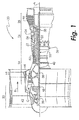
FIG. 1 is a sectional view of a gas turbine engine in an embodiment. -
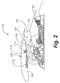
FIG. 2 is a sectional view of a gas turbine engine in an embodiment. -
FIG. 3 is a sectional view of a structural guide vane in an embodiment. -
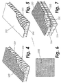
FIG. 4 is a perspective view of an acoustic liner in an embodiment. -
FIG. 5 is a perspective view of an acoustic liner in an embodiment. -
FIG. 6 is a perspective view of an acoustic liner in an embodiment, -
FIG. 7 is a perspective view of an acoustic liner in an embodiment. - For the purposes of promoting an understanding of the principles of the present disclosure, reference will now be made to the embodiments illustrated in the drawings, and specific language will be used to describe the same. It will nevertheless be understood that no limitation of the scope of this disclosure is thereby intended.
-
FIG. 1 shows agas turbine engine 20, such as a gas turbine used for power generation or propulsion, circumferentially disposed about an engine centerline, or axial centerline axis A. Thegas turbine engine 20 is disclosed herein as a two-spool turbofan that generally incorporates afan section 22, acompressor section 24, acombustor section 26 and aturbine section 28. Alternative engines might include an augmentor section (not shown) among other systems or features. Thefan section 22 drives air along a bypass flow path B in a bypass duct, while thecompressor section 24 drives air along a core flow path C for compression and communication into thecombustor section 26 then expansion through theturbine section 28. Although depicted as a two-spool turbofan gas turbine engine in the disclosed non-limiting embodiment, it should be understood that the concepts described herein are not limited to use with two-spool turbofans as the teachings may be applied to other types of turbine engines including three-spool architectures. - The
exemplary engine 20 generally includes alow speed spool 30 and ahigh speed spool 32 mounted for rotation about an engine central longitudinal axis A relative to an enginestatic structure 36 viaseveral bearing systems 38. It should be understood that various bearingsystems 38 at various locations may alternatively or additionally be provided, and the location of bearingsystems 38 may be varied as appropriate to the application. - The
low speed spool 30 generally includes aninner shaft 40 that interconnects afan 42, alow pressure compressor 44 and alow pressure turbine 46. Theinner shaft 40 is connected to thefan 42 through a speed change mechanism, which in exemplarygas turbine engine 20 is illustrated as a gearedarchitecture 48 to drive thefan 42 at a lower speed than thelow speed spool 30. Thehigh speed spool 32 includes anouter shaft 50 that interconnects ahigh pressure compressor 52 andhigh pressure turbine 54. Acombustor 56 is arranged inexemplary gas turbine 20 between thehigh pressure compressor 52 and thehigh pressure turbine 54. An enginestatic structure 36 is arranged generally between thehigh pressure turbine 54 and thelow pressure turbine 46. The enginestatic structure 36 furthersupports bearing systems 38 in theturbine section 28. Theinner shaft 40 and theouter shaft 50 are concentric and rotate via bearingsystems 38 about the engine central longitudinal axis A which is collinear with their longitudinal axes. - The core airflow is compressed by the
low pressure compressor 44 then thehigh pressure compressor 52, mixed and burned with fuel in thecombustor 56, then expanded over thehigh pressure turbine 54 andlow pressure turbine 46. Theturbines low speed spool 30 andhigh speed spool 32 in response to the expansion. It will be appreciated that each of the positions of thefan section 22,compressor section 24,combustor section 26,turbine section 28, and fandrive gear system 48 may be varied. For example,gear system 48 may be located aft ofcombustor section 26 or even aft ofturbine section 28, andfan section 22 may be positioned forward or aft of the location ofgear system 48. - The
engine 20 in one example is a high-bypass geared aircraft engine. In a further example, theengine 20 bypass ratio is greater than about six (6), with an example embodiment being greater than about ten (10), the gearedarchitecture 48 is an epicyclic gear train, such as a planetary gear system or other gear system, with a gear reduction ratio of greater than about 2.3 and thelow pressure turbine 46 has a pressure ratio that is greater than about five. In one disclosed embodiment, theengine 20 bypass ratio is greater than about ten (10:1), the fan diameter is significantly larger than that of thelow pressure compressor 44, and thelow pressure turbine 46 has a pressure ratio that is greater than about five 5:1.Low pressure turbine 46 pressure ratio is pressure measured prior to inlet oflow pressure turbine 46 as related to the pressure at the outlet of thelow pressure turbine 46 prior to an exhaust nozzle. The gearedarchitecture 48 may be an epicycle gear train, such as a planetary gear system or other gear system, with a gear reduction ratio of greater than about 2.3:1. It should be understood, however, that the above parameters are only exemplary of one embodiment of a geared architecture engine and that the present invention is applicable to other gas turbine engines including direct drive turbofans. - A significant amount of thrust is provided by the bypass flow B due to the high bypass ratio. The
fan section 22 of theengine 20 is designed for a particular flight conditiontypically cruise at about 0.8 Mach and about 35,000 feet (10,688 meters). The flight condition of 0.8 Mach and 35,000 ft. (10,688 meters), with the engine at its best fuel consumption - also known as "bucket cruise Thrust Specific Fuel Consumption ('TSFC')" - is the industry standard parameter of Ibm of fuel being burned divided by lbf of thrust the engine produces at that minimum point. "Low fan pressure ratio" is the pressure ratio across the fan blade alone, without a Fan Exit Guide Vane ("FEGV") or Structural Guide Vane ("SGV") system. The low fan pressure ratio as disclosed herein according to one non-limiting embodiment is less than about 1.45. "Low corrected fan tip speed" is the actual fan tip speed in ft/sec divided by an industry standard temperature correction of [(Tfan °R) / (518.7 °R)]0.5. The "Low corrected fan tip speed" as disclosed herein according to one non-limiting embodiment is less than about 1150 ft / second (350.5 m/sec). -
FIG. 2 illustrates agas turbine engine 100 having aflow channel 102 extending between aninlet 104 and an innerfixed structure 106. Theflow channel 102 is defined by aninner diameter 108 and anouter diameter 110. Afan case 112 is positioned downstream of theinlet 104. Aninner diameter splitter 114 is positioned downstream from thefan case 112 and extends along theinner diameter 108. Astructural guide vane 116 is positioned downstream from thefan case 112 and theinner diameter splitter 114. Thestructural guide vane 116 defines an outerdiameter vane passage 118 along theouter diameter 110 and an inner diameter vane passage 120 along theinner diameter 108. Thestructural guide vane 116 includes aleading edge 122 and a trailingedge 124. Ablocker door 126 is positioned downstream from thestructural guide vane 116 along theouter diameter 110. The inner fixedstructure 106 is positioned downstream of thestructural guide vane 116 along theinner diameter 108. A translatingsleeve 127 is positioned downstream from the inner fixedstructure 106 along theinner diameter 108. - The embodiments described herein use an engine and/or nacelle liner 200, for example the liners described below with respect to
FIG. 3 , to reduce the vibratory stress on thestructural guide vane 116. Liner 200 depth and porousness, as well as placement in relation to thestructural guide vane 116, are designed for the purposes of reducing vibratory stress. In one embodiment, a liner 200 is positioned between anaft end 128 of thefan case 112 and an aft end 129 of the translatingsleeve 127 to reduce vibratory stress on thestructural guide vane 116. Alternatively, the liner 200 has a thickness capable of attenuating vibrations having a frequency of less than 1,000 Hertz. Optionally, the liner 200 is positioned along theouter diameter 110 between theaft end 128 of thefan case 112 and theleading edge 122 of thestructural guide vane 116. In another embodiment, the liner 200 is positioned along theinner diameter 108 in the inner diameter vane passage 120. In an alternative embodiment, the liner 200 is positioned along theouter diameter 110 in the outerdiameter vane passage 118. In one embodiment, the liner 200 is positioned along theinner diameter splitter 114. Optionally, the liner 200 is positioned along theouter diameter 110 between the trailingedge 124 of thestructural guide vane 116 and theblocker door 126. Alternatively, the liner 200 is positioned along theinner diameter 108 between the trailingedge 124 of thestructural guide vane 116 and the inner fixedstructure 106. In other embodiments, the liner is positioned along theouter diameter 110 along theblocker door 126. In an alternative embodiment, the liner is positioned on the inner fixedstructure 106. In one embodiment, the liner is positioned on the translatingsleeve 127. - By tuning the liner 200 to the frequency and speed of the resonant crossing, the energy of the system is attenuated, and the unsteady pressure response of the
structural guide vane 116 is reduced, thereby reducing the component vibratory resonant stress of the mode(s) selected. An engine and nacelle liner 200 tuned to a particular structural guide vane's mode shape at its resonant crossing will change the unsteady pressure on thestructural guide vane 116 due to the rotor-wake/stator vane interaction. The liner 200 will also reduce the component vibratory stress of thestructural guide vane 116. The reduction in stress is achieved without modifications to the structural guide vane's 116 structural or aerodynamic properties. - In order to demonstrate the benefit of tuning the liner 200 to a structural guide vane mode shape, the second torsion mode shape of the structural guide vane is selected, wherein the resonant crossing for the mode occurs at 725Hz and a mechanical speed of 2486 RPM. Three resonant stress predictions are calculated: 1) a hard-wall flow channel geometry with no liner; 2) a flow channel with liner properties tuned for noise mitigation only; and 3) a flow channel with liner properties tuned to reduce vibratory stresses, as shown in
FIG. 3 . In case 1, there is no liner treatment in the analytical model. This case serves as a baseline, hard-wall flow channel. The second case models the typical liner locations of the engine. The third case tunes the current engine liner configuration to the torsion mode frequency at a Mach number of 0.4. - Case 3, illustrated in
FIG. 3 , includes patches of liner 200 along the wall of theflow channel 102. The patches include individual segments of liner 200 that are utilized to cover a portion of the wall of theflow channel 102. Each patch is independent of every other patch, although some patches may abut one another. Twopatches outer diameter 210, whereinpatches vane leading edge 122. Anotherpatch 200C is aft of thevane trailing edge 124. Anotherpatch 200D is on theinner diameter 108 and is aft of thevane trailing edge 124. The following table summarizes the impedance values used in Cases 2 and 3.Case Patch 200APatch 200BPatch 200CPatch 200D Resistance Reactance Resistance Reactance Resistance Reactance Resistance Reactance 2 1.5702 -3.0142 1.5329 -8.1568 1.2094 -3.2530 0.9494 2.3928 3 0.4000 -0.6000 0.4000 -0.6000 0.5700 -0.2500 0.5700 -0.2500 - The following table gives a summary of the predicted vibratory stress for these three cases. The results demonstrate that a liner 200 tuned for acoustic purposes may help reduce the vibratory stress when compared to a no-liner, hard-wall configuration. An 11 % reduction is predicted when comparing case 2 (liner tuned only for noise mitigation) to case 1. However, tuning the liner of case 2 to the torsion mode resonant frequency of the structural guide vane 116 (case 3) shows a much large reduction in vibratory stress, wherein a 50% reduction is achieved over the hard wall configuration.
Case Number Case Description Predicted Component Vibratory Stress Percent Change from Case 1 1 Hard wall annular duct geometry (no liner) 4.4 ksi 0% 2 Annular duct with liner properties tuned for noise mitigation 3.9 ksi -11% 3 Case (2) with liner properties optimally tuned to reduce vibratory stress 2.2 ksi -50% -
Figs. 4-7 illustrate exemplary acoustic liners 200 that are composed of arigid backsheet 250, aporous facesheet 252, and ahoneycomb mid-layer 254. Theporous facesheet 252 may consist of perforated plate (FIG. 4 ), a woven mesh (FIG. 5 ), or a micro-perforated plate (FIG. 6 ). The liner 200 may also contain multiple layers of honeycomb (FIG. 7 ). Other liner construction may also be considered when targeting the resonant frequency of the airfoil. For example, also using a mid-layer construction consisting of volumes rather than honeycomb may better target the frequencies of concern. The depth of the honeycomb cells or the size of the volumes in the mid-layer is chosen to control the frequency at which max attenuation occurs. The deeper the liner or larger the size of the volumes, the lower the frequency it attenuates. - While the embodiments have been illustrated and described in detail in the drawings and foregoing description, the same is to be considered as illustrative and not restrictive in character, it being understood that only certain embodiments have been shown and described and that all changes and modifications that come within the scope of the embodiments are desired to be protected.
- The following clauses set out features of the present disclosure which may or may not presently be claimed but which may serve as basis for future amendments and/or a divisional application.
- 1. A gas turbine engine comprising:
- a fan case;
- a translating sleeve positioned downstream from the fan case;
- a flow channel extending between the fan case and the translating sleeve, the flow channel including an inner diameter and an outer diameter;
- a structural guide vane positioned within the flow channel and extending from the inner diameter to the outer diameter; and
- a liner positioned between an aft end of the fan case and an aft end of the translating sleeve to reduce vibratory stress on the structural guide vane.
- 2. The gas turbine engine of clause 1, wherein the liner includes a thickness capable of attenuating vibrations having a frequency of less than 1,000 Hertz.
- 3. The gas turbine engine of clause 1, wherein the structural guide vane includes a leading edge and a trailing edge, the liner positioned along the outer diameter between the aft end of the fan case and a leading edge of the structural guide vane.
- 4. The gas turbine engine of clause 1, wherein the structural guide vane defines an inner diameter vane passage and an outer diameter vane passage, the liner positioned along the inner diameter in the inner diameter vane passage.
- 5. The gas turbine engine of clause 1, wherein the structural guide vane defines an inner diameter vane passage and an outer diameter vane passage, the liner positioned along the outer diameter in the outer diameter vane passage.
- 6. The gas turbine engine of clause 1, wherein the inner diameter of the flow channel includes an inner diameter splitter, the liner positioned along the inner diameter splitter.
- 7. The gas turbine engine of clause 1, wherein the structural guide vane includes a leading edge and a trailing edge, the liner positioned along the outer diameter between the trailing edge of the structural guide vane and the translating sleeve.
- 8. The gas turbine engine of clause 1 further comprising an inner fixed structure extending along the inner diameter of the flow channel, wherein the structural guide vane includes a leading edge and a trailing edge, the liner positioned along the inner diameter between the trailing edge of the structural guide vane and the inner fixed structure.
- 9. The gas turbine engine of clause 1, wherein the liner is positioned along the outer diameter along the translating sleeve.
- 10. A method of reducing vibratory stress on a structural guide vane extending between an inner diameter and outer diameter of a flow channel formed between a fan case and a translating sleeve, the method comprising:
- forming a liner including a thickness capable of attenuating vibrations having a frequency of less than 1,000 Hertz; and
- positioning the liner between an aft end of the fan case and an aft end of the translating sleeve.
- 11. The method of clause 10, wherein the structural guide vane includes a leading edge and a trailing edge, the method further comprising positioning the liner along the outer diameter between the aft end of the fan case and a leading edge of the structural guide vane.
- 12. The method of clause 10, wherein the structural guide vane defines an inner diameter vane passage and an outer diameter vane passage, the method further comprising positioning the liner along the inner diameter in the inner diameter vane passage.
- 13. The method of clause 10, wherein the structural guide vane defines an inner diameter vane passage and an outer diameter vane passage, the method further comprising positioning the liner along the outer diameter in the outer diameter vane passage.
- 14. The method of clause 10, wherein the inner diameter of the flow channel includes an inner diameter splitter, the method further comprising positioning the liner along the inner diameter splitter.
- 15. The method of clause 10, wherein the structural guide vane includes a leading edge and a trailing edge, the method further comprising positioning the liner along the outer diameter between the trailing edge of the structural guide vane and the translating sleeve.
- 16. The method of clause 10, wherein the gas turbine engine includes an inner fixed structure extending along the inner diameter of the flow channel, wherein the structural guide vane includes a leading edge and a trailing edge, the method further comprising positioning the liner along the inner diameter between the trailing edge of the structural guide vane and the inner fixed structure.
- 17. The method of clause 10 further comprising positioning the liner along the outer diameter along the translating sleeve.
- 18. A system comprising:
- a flow channel including an inner diameter and an outer diameter;
- a structural guide vane extending between the inner diameter and the outer diameter;
- a rotating member configured to rotate adjacent to the structural guide vane;
- a liner positioned on at least one of the inner diameter and the outer diameter to attenuate vibrations from the rotating member having a frequency of less than 1,000 Hertz to reduce vibratory stress on the structural guide vane.
- 19. The system of clause 18, wherein the liner is positioned adjacent the structural guide vane.
- 20. The system of clause 18, wherein the structural guide vane defines an inner diameter vane passage and an outer diameter vane passage, the liner positioned along at least one of the inner diameter vane passage or the outer diameter vane passage.
Claims (15)
- A gas turbine engine (100) comprising:a fan case (112);a translating sleeve (127) positioned downstream from the fan case;a flow channel (102) extending between the fan case and the translating sleeve, the flow channel including an inner diameter (108) and an outer diameter (110);a structural guide vane (116) positioned within the flow channel and extending from the inner diameter to the outer diameter; anda liner (200) positioned between an aft end (128) of the fan case and an aft end (129) of the translating sleeve to reduce vibratory stress on the structural guide vane.
- The gas turbine engine (100) of claim 1, wherein the liner (200) includes a thickness capable of attenuating vibrations having a frequency of less than 1,000 Hertz.
- The gas turbine engine (100) of claim 1 or 2, wherein the structural guide vane (116) includes a leading edge (122) and a trailing edge (124), the liner (200) positioned along the outer diameter (110) between the aft end (128) of the fan case (112) and the leading edge of the structural guide vane; and/or
the liner positioned along the outer diameter between the trailing edge of the structural guide vane and the translating sleeve (127). - The gas turbine engine (100) of claim 1, 2 or 3, wherein the structural guide vane (116) defines an inner diameter vane passage and an outer diameter vane passage (118), the liner (200) positioned along the inner diameter (108) in the inner diameter vane passage; and/or
the liner positioned along the outer diameter (110) in the outer diameter vane passage. - The gas turbine engine (100) of any preceding claim, wherein the inner diameter (108) of the flow channel (102) includes an inner diameter splitter (114), the liner (200) positioned along the inner diameter splitter; and/or
wherein the liner (200) is positioned along the outer diameter (110) along the translating sleeve (127). - The gas turbine engine (100) of any preceding claim further comprising an inner fixed structure (106) extending along the inner diameter (108) of the flow channel (102), wherein the structural guide vane (116) includes a leading edge (122) and a trailing edge (124), the liner (200) positioned along the inner diameter between the trailing edge of the structural guide vane and the inner fixed structure.
- A method of reducing vibratory stress on a structural guide vane (116) extending between an inner diameter (108) and outer diameter (110) of a flow channel (102) formed between a fan case (112) and a translating sleeve (127), the method comprising:forming a liner (200) including a thickness capable of attenuating vibrations having a frequency of less than 1,000 Hertz; andpositioning the liner between an aft end (128) of the fan case and an aft end (129) of the translating sleeve.
- The method of claim 7, wherein the structural guide vane (116) includes a leading edge (122) and a trailing edge (124), the method further comprising positioning the liner (200) along the outer diameter (110) between the aft end (128) of the fan case (112) and the leading edge (122) of the structural guide vane; and/or
positioning the liner along the outer diameter between the trailing edge of the structural guide vane and the translating sleeve (127). - The method of claim 7 or 8, wherein the structural guide vane (116) defines an inner diameter vane passage and an outer diameter vane passage (118), the method further comprising positioning the liner (200) along the inner diameter (108) in the inner diameter vane passage; and/or
positioning the liner along the outer diameter (110) in the outer diameter vane passage. - The method of claim 7, 8 or 9, wherein the inner diameter (108) of the flow channel (102) includes an inner diameter splitter (114), the method further comprising positioning the liner (200) along the inner diameter splitter.
- The method of claim 7, 8, 9 or 10, wherein an inner fixed structure (106) extends along the inner diameter (108) of the flow channel (102), wherein the structural guide vane (116) includes a leading edge (122) and a trailing edge (124), the method further comprising positioning the liner (200) along the inner diameter between the trailing edge of the structural guide vane and the inner fixed structure.
- The method of claim 7, 8, 9, 10 or 11 further comprising positioning the liner (200) along the outer diameter (110) along the translating sleeve (127).
- A system comprising:a flow channel (102) including an inner diameter (108) and an outer diameter (110);a structural guide vane (116) extending between the inner diameter and the outer diameter;a rotating member configured to rotate adjacent to the structural guide vane;a liner (200) positioned on at least one of the inner diameter and the outer diameter to attenuate vibrations from the rotating member having a frequency of less than 1,000 Hertz to reduce vibratory stress on the structural guide vane.
- The system of claim 13, wherein the liner (200) is positioned adjacent the structural guide vane (116).
- The system of claim 13 or 14, wherein the structural guide vane (116) defines an inner diameter vane passage and an outer diameter vane passage (118), the liner positioned along at least one of the inner diameter vane passage or the outer diameter vane passage.
Applications Claiming Priority (1)
| Application Number | Priority Date | Filing Date | Title |
|---|---|---|---|
| US14/706,259 US10371173B2 (en) | 2015-05-07 | 2015-05-07 | Liner for a gas turbine engine |
Publications (2)
| Publication Number | Publication Date |
|---|---|
| EP3091216A1 true EP3091216A1 (en) | 2016-11-09 |
| EP3091216B1 EP3091216B1 (en) | 2019-12-04 |
Family
ID=55919762
Family Applications (1)
| Application Number | Title | Priority Date | Filing Date |
|---|---|---|---|
| EP16168799.1A Active EP3091216B1 (en) | 2015-05-07 | 2016-05-09 | Liner for a gas turbine engine |
Country Status (2)
| Country | Link |
|---|---|
| US (1) | US10371173B2 (en) |
| EP (1) | EP3091216B1 (en) |
Cited By (2)
| Publication number | Priority date | Publication date | Assignee | Title |
|---|---|---|---|---|
| FR3092137A1 (en) * | 2019-01-30 | 2020-07-31 | Safran Aircraft Engines | Turbomachine stator sector with high stress areas |
| EP3799030A1 (en) * | 2019-09-26 | 2021-03-31 | Rolls-Royce Deutschland Ltd & Co KG | Acoustic liner and gas turbine engine with such acoustic liner |
Families Citing this family (7)
| Publication number | Priority date | Publication date | Assignee | Title |
|---|---|---|---|---|
| US10107191B2 (en) * | 2012-02-29 | 2018-10-23 | United Technologies Corporation | Geared gas turbine engine with reduced fan noise |
| DE102015216208A1 (en) * | 2015-08-25 | 2017-03-02 | Rolls-Royce Deutschland Ltd & Co Kg | Sealing element for a turbomachine, turbomachine with a sealing element and method for producing a sealing element |
| US11591958B2 (en) * | 2019-06-14 | 2023-02-28 | Pratt & Whitney Canada Corp. | Turbofan engine with acoustic treatment |
| US11674415B2 (en) | 2021-08-20 | 2023-06-13 | Raytheon Technologies Corporation | Front section stiffness ratio |
| US11555420B1 (en) * | 2021-08-20 | 2023-01-17 | Raytheon Technologies Corporation | Frame connection between fan case and core housing in a gas turbine engine |
| US20250250922A1 (en) * | 2024-02-01 | 2025-08-07 | Solar Turbines Incorporated | Sound-attenuating devices |
| CN118775348B (en) * | 2024-09-12 | 2024-12-03 | 本元智慧科技有限公司 | A noise reduction structure and noise reduction method for a magnetic suspension blower |
Citations (3)
| Publication number | Priority date | Publication date | Assignee | Title |
|---|---|---|---|---|
| US7784283B2 (en) * | 2006-05-03 | 2010-08-31 | Rohr, Inc. | Sound-absorbing exhaust nozzle center plug |
| US7870929B2 (en) * | 2008-04-29 | 2011-01-18 | The Boeing Company | Engine assembly, acoustical liner and associated method of fabrication |
| WO2014197035A2 (en) * | 2013-03-15 | 2014-12-11 | United Technologies Corporation | Acoustic liner with varied properties |
Family Cites Families (11)
| Publication number | Priority date | Publication date | Assignee | Title |
|---|---|---|---|---|
| FR2613773B1 (en) * | 1987-04-08 | 1990-11-30 | Snecma | ACOUSTIC PANEL FOR SOUNDPROOFING AND TURBOREACTOR COMPRISING SUCH A TRIM |
| US5060471A (en) * | 1989-11-06 | 1991-10-29 | 501 Nordam | Jet engine noise reduction system |
| US5478199A (en) * | 1994-11-28 | 1995-12-26 | General Electric Company | Active low noise fan assembly |
| GB0119608D0 (en) | 2001-08-11 | 2001-10-03 | Rolls Royce Plc | A guide vane assembly |
| US7328771B2 (en) | 2004-07-27 | 2008-02-12 | United Technologies Corporation | Zero acoustic splice fan case liner |
| GB0803479D0 (en) | 2008-02-27 | 2008-04-02 | Rolls Royce Plc | Fan track liner assembly |
| GB2459844B (en) | 2008-05-06 | 2011-01-19 | Rolls Royce Plc | Fan section |
| GB0914679D0 (en) | 2009-08-24 | 2009-09-30 | Rolls Royce Plc | Adjustable fan case liner and mounting method |
| FR2965859B1 (en) * | 2010-10-07 | 2012-11-02 | Snecma | DEVICE FOR ACOUSTICALLY PROCESSING NOISE EMITTED BY A TURBOJETACTOR |
| GB201209658D0 (en) * | 2012-05-31 | 2012-07-11 | Rolls Royce Plc | Acoustic panel |
| US9702375B2 (en) | 2013-07-16 | 2017-07-11 | United Technologies Corporation | Liner attaching scheme |
-
2015
- 2015-05-07 US US14/706,259 patent/US10371173B2/en active Active
-
2016
- 2016-05-09 EP EP16168799.1A patent/EP3091216B1/en active Active
Patent Citations (3)
| Publication number | Priority date | Publication date | Assignee | Title |
|---|---|---|---|---|
| US7784283B2 (en) * | 2006-05-03 | 2010-08-31 | Rohr, Inc. | Sound-absorbing exhaust nozzle center plug |
| US7870929B2 (en) * | 2008-04-29 | 2011-01-18 | The Boeing Company | Engine assembly, acoustical liner and associated method of fabrication |
| WO2014197035A2 (en) * | 2013-03-15 | 2014-12-11 | United Technologies Corporation | Acoustic liner with varied properties |
Cited By (7)
| Publication number | Priority date | Publication date | Assignee | Title |
|---|---|---|---|---|
| FR3092137A1 (en) * | 2019-01-30 | 2020-07-31 | Safran Aircraft Engines | Turbomachine stator sector with high stress areas |
| WO2020157405A1 (en) * | 2019-01-30 | 2020-08-06 | Safran Aircraft Engines | Turbomachine stator sector having flexible regions subjected to high stress |
| CN113366192A (en) * | 2019-01-30 | 2021-09-07 | 赛峰航空器发动机 | Turbine stator sector with compliant regions subject to high stresses |
| US11767767B2 (en) | 2019-01-30 | 2023-09-26 | Safran Aircraft Engines | Turbomachine stator sector having flexible regions subjected to high stress |
| CN113366192B (en) * | 2019-01-30 | 2024-04-02 | 赛峰航空器发动机 | Turbine stator sector with flexible regions subjected to high stresses |
| EP3799030A1 (en) * | 2019-09-26 | 2021-03-31 | Rolls-Royce Deutschland Ltd & Co KG | Acoustic liner and gas turbine engine with such acoustic liner |
| US12134996B2 (en) | 2019-09-26 | 2024-11-05 | Rolls-Royce Deutschland Ltd & Co Kg | Acoustic liner and gas turbine engine with such acoustic liner |
Also Published As
| Publication number | Publication date |
|---|---|
| EP3091216B1 (en) | 2019-12-04 |
| US20160327064A1 (en) | 2016-11-10 |
| US10371173B2 (en) | 2019-08-06 |
Similar Documents
| Publication | Publication Date | Title |
|---|---|---|
| EP3091216B1 (en) | Liner for a gas turbine engine | |
| EP3869499B1 (en) | Acoustic liner with non-uniform volumetric distribution | |
| US10066548B2 (en) | Acoustic liner with varied properties | |
| US9890657B2 (en) | Acoustic treatment in geared turbomachine | |
| US10837367B2 (en) | Acoustic treatment in an unducted area of a geared turbomachine | |
| EP2961959B1 (en) | Acoustic treatment to mitigate fan noise | |
| US10415506B2 (en) | Multi degree of freedom flutter damper | |
| EP3372817B1 (en) | Flutter inhibiting intake for gas turbine propulsion system | |
| EP3372807B1 (en) | Flutter dampening acoustic liner for a turbofan engine | |
| US10612464B2 (en) | Flutter inhibiting intake for gas turbine propulsion system | |
| US20160194968A1 (en) | High performance convergent divergent nozzle | |
| EP3372814B1 (en) | Asymmetric multi degree of freedom flutter damper | |
| EP3102791A2 (en) | Compressed chopped fiber composite fan blade platform | |
| EP3392567A1 (en) | Combustor liner panel end rail |
Legal Events
| Date | Code | Title | Description |
|---|---|---|---|
| PUAI | Public reference made under article 153(3) epc to a published international application that has entered the european phase |
Free format text: ORIGINAL CODE: 0009012 |
|
| AK | Designated contracting states |
Kind code of ref document: A1 Designated state(s): AL AT BE BG CH CY CZ DE DK EE ES FI FR GB GR HR HU IE IS IT LI LT LU LV MC MK MT NL NO PL PT RO RS SE SI SK SM TR |
|
| AX | Request for extension of the european patent |
Extension state: BA ME |
|
| STAA | Information on the status of an ep patent application or granted ep patent |
Free format text: STATUS: REQUEST FOR EXAMINATION WAS MADE |
|
| 17P | Request for examination filed |
Effective date: 20170509 |
|
| RBV | Designated contracting states (corrected) |
Designated state(s): AL AT BE BG CH CY CZ DE DK EE ES FI FR GB GR HR HU IE IS IT LI LT LU LV MC MK MT NL NO PL PT RO RS SE SI SK SM TR |
|
| STAA | Information on the status of an ep patent application or granted ep patent |
Free format text: STATUS: EXAMINATION IS IN PROGRESS |
|
| 17Q | First examination report despatched |
Effective date: 20170830 |
|
| GRAP | Despatch of communication of intention to grant a patent |
Free format text: ORIGINAL CODE: EPIDOSNIGR1 |
|
| STAA | Information on the status of an ep patent application or granted ep patent |
Free format text: STATUS: GRANT OF PATENT IS INTENDED |
|
| INTG | Intention to grant announced |
Effective date: 20190614 |
|
| GRAS | Grant fee paid |
Free format text: ORIGINAL CODE: EPIDOSNIGR3 |
|
| GRAA | (expected) grant |
Free format text: ORIGINAL CODE: 0009210 |
|
| STAA | Information on the status of an ep patent application or granted ep patent |
Free format text: STATUS: THE PATENT HAS BEEN GRANTED |
|
| AK | Designated contracting states |
Kind code of ref document: B1 Designated state(s): AL AT BE BG CH CY CZ DE DK EE ES FI FR GB GR HR HU IE IS IT LI LT LU LV MC MK MT NL NO PL PT RO RS SE SI SK SM TR |
|
| REG | Reference to a national code |
Ref country code: GB Ref legal event code: FG4D |
|
| REG | Reference to a national code |
Ref country code: CH Ref legal event code: EP |
|
| REG | Reference to a national code |
Ref country code: AT Ref legal event code: REF Ref document number: 1209710 Country of ref document: AT Kind code of ref document: T Effective date: 20191215 |
|
| REG | Reference to a national code |
Ref country code: DE Ref legal event code: R096 Ref document number: 602016025368 Country of ref document: DE |
|
| REG | Reference to a national code |
Ref country code: IE Ref legal event code: FG4D |
|
| REG | Reference to a national code |
Ref country code: NL Ref legal event code: MP Effective date: 20191204 |
|
| REG | Reference to a national code |
Ref country code: LT Ref legal event code: MG4D |
|
| PG25 | Lapsed in a contracting state [announced via postgrant information from national office to epo] |
Ref country code: LT Free format text: LAPSE BECAUSE OF FAILURE TO SUBMIT A TRANSLATION OF THE DESCRIPTION OR TO PAY THE FEE WITHIN THE PRESCRIBED TIME-LIMIT Effective date: 20191204 Ref country code: GR Free format text: LAPSE BECAUSE OF FAILURE TO SUBMIT A TRANSLATION OF THE DESCRIPTION OR TO PAY THE FEE WITHIN THE PRESCRIBED TIME-LIMIT Effective date: 20200305 Ref country code: NO Free format text: LAPSE BECAUSE OF FAILURE TO SUBMIT A TRANSLATION OF THE DESCRIPTION OR TO PAY THE FEE WITHIN THE PRESCRIBED TIME-LIMIT Effective date: 20200304 Ref country code: SE Free format text: LAPSE BECAUSE OF FAILURE TO SUBMIT A TRANSLATION OF THE DESCRIPTION OR TO PAY THE FEE WITHIN THE PRESCRIBED TIME-LIMIT Effective date: 20191204 Ref country code: LV Free format text: LAPSE BECAUSE OF FAILURE TO SUBMIT A TRANSLATION OF THE DESCRIPTION OR TO PAY THE FEE WITHIN THE PRESCRIBED TIME-LIMIT Effective date: 20191204 Ref country code: FI Free format text: LAPSE BECAUSE OF FAILURE TO SUBMIT A TRANSLATION OF THE DESCRIPTION OR TO PAY THE FEE WITHIN THE PRESCRIBED TIME-LIMIT Effective date: 20191204 Ref country code: BG Free format text: LAPSE BECAUSE OF FAILURE TO SUBMIT A TRANSLATION OF THE DESCRIPTION OR TO PAY THE FEE WITHIN THE PRESCRIBED TIME-LIMIT Effective date: 20200304 |
|
| PG25 | Lapsed in a contracting state [announced via postgrant information from national office to epo] |
Ref country code: HR Free format text: LAPSE BECAUSE OF FAILURE TO SUBMIT A TRANSLATION OF THE DESCRIPTION OR TO PAY THE FEE WITHIN THE PRESCRIBED TIME-LIMIT Effective date: 20191204 Ref country code: RS Free format text: LAPSE BECAUSE OF FAILURE TO SUBMIT A TRANSLATION OF THE DESCRIPTION OR TO PAY THE FEE WITHIN THE PRESCRIBED TIME-LIMIT Effective date: 20191204 |
|
| PG25 | Lapsed in a contracting state [announced via postgrant information from national office to epo] |
Ref country code: AL Free format text: LAPSE BECAUSE OF FAILURE TO SUBMIT A TRANSLATION OF THE DESCRIPTION OR TO PAY THE FEE WITHIN THE PRESCRIBED TIME-LIMIT Effective date: 20191204 |
|
| PG25 | Lapsed in a contracting state [announced via postgrant information from national office to epo] |
Ref country code: PT Free format text: LAPSE BECAUSE OF FAILURE TO SUBMIT A TRANSLATION OF THE DESCRIPTION OR TO PAY THE FEE WITHIN THE PRESCRIBED TIME-LIMIT Effective date: 20200429 Ref country code: ES Free format text: LAPSE BECAUSE OF FAILURE TO SUBMIT A TRANSLATION OF THE DESCRIPTION OR TO PAY THE FEE WITHIN THE PRESCRIBED TIME-LIMIT Effective date: 20191204 Ref country code: RO Free format text: LAPSE BECAUSE OF FAILURE TO SUBMIT A TRANSLATION OF THE DESCRIPTION OR TO PAY THE FEE WITHIN THE PRESCRIBED TIME-LIMIT Effective date: 20191204 Ref country code: NL Free format text: LAPSE BECAUSE OF FAILURE TO SUBMIT A TRANSLATION OF THE DESCRIPTION OR TO PAY THE FEE WITHIN THE PRESCRIBED TIME-LIMIT Effective date: 20191204 Ref country code: CZ Free format text: LAPSE BECAUSE OF FAILURE TO SUBMIT A TRANSLATION OF THE DESCRIPTION OR TO PAY THE FEE WITHIN THE PRESCRIBED TIME-LIMIT Effective date: 20191204 Ref country code: EE Free format text: LAPSE BECAUSE OF FAILURE TO SUBMIT A TRANSLATION OF THE DESCRIPTION OR TO PAY THE FEE WITHIN THE PRESCRIBED TIME-LIMIT Effective date: 20191204 |
|
| PG25 | Lapsed in a contracting state [announced via postgrant information from national office to epo] |
Ref country code: SM Free format text: LAPSE BECAUSE OF FAILURE TO SUBMIT A TRANSLATION OF THE DESCRIPTION OR TO PAY THE FEE WITHIN THE PRESCRIBED TIME-LIMIT Effective date: 20191204 Ref country code: IS Free format text: LAPSE BECAUSE OF FAILURE TO SUBMIT A TRANSLATION OF THE DESCRIPTION OR TO PAY THE FEE WITHIN THE PRESCRIBED TIME-LIMIT Effective date: 20200404 Ref country code: SK Free format text: LAPSE BECAUSE OF FAILURE TO SUBMIT A TRANSLATION OF THE DESCRIPTION OR TO PAY THE FEE WITHIN THE PRESCRIBED TIME-LIMIT Effective date: 20191204 |
|
| REG | Reference to a national code |
Ref country code: DE Ref legal event code: R097 Ref document number: 602016025368 Country of ref document: DE |
|
| REG | Reference to a national code |
Ref country code: AT Ref legal event code: MK05 Ref document number: 1209710 Country of ref document: AT Kind code of ref document: T Effective date: 20191204 |
|
| PLBE | No opposition filed within time limit |
Free format text: ORIGINAL CODE: 0009261 |
|
| STAA | Information on the status of an ep patent application or granted ep patent |
Free format text: STATUS: NO OPPOSITION FILED WITHIN TIME LIMIT |
|
| PG25 | Lapsed in a contracting state [announced via postgrant information from national office to epo] |
Ref country code: DK Free format text: LAPSE BECAUSE OF FAILURE TO SUBMIT A TRANSLATION OF THE DESCRIPTION OR TO PAY THE FEE WITHIN THE PRESCRIBED TIME-LIMIT Effective date: 20191204 |
|
| 26N | No opposition filed |
Effective date: 20200907 |
|
| PG25 | Lapsed in a contracting state [announced via postgrant information from national office to epo] |
Ref country code: AT Free format text: LAPSE BECAUSE OF FAILURE TO SUBMIT A TRANSLATION OF THE DESCRIPTION OR TO PAY THE FEE WITHIN THE PRESCRIBED TIME-LIMIT Effective date: 20191204 Ref country code: SI Free format text: LAPSE BECAUSE OF FAILURE TO SUBMIT A TRANSLATION OF THE DESCRIPTION OR TO PAY THE FEE WITHIN THE PRESCRIBED TIME-LIMIT Effective date: 20191204 Ref country code: PL Free format text: LAPSE BECAUSE OF FAILURE TO SUBMIT A TRANSLATION OF THE DESCRIPTION OR TO PAY THE FEE WITHIN THE PRESCRIBED TIME-LIMIT Effective date: 20191204 |
|
| PG25 | Lapsed in a contracting state [announced via postgrant information from national office to epo] |
Ref country code: CH Free format text: LAPSE BECAUSE OF NON-PAYMENT OF DUE FEES Effective date: 20200531 Ref country code: IT Free format text: LAPSE BECAUSE OF FAILURE TO SUBMIT A TRANSLATION OF THE DESCRIPTION OR TO PAY THE FEE WITHIN THE PRESCRIBED TIME-LIMIT Effective date: 20191204 Ref country code: LI Free format text: LAPSE BECAUSE OF NON-PAYMENT OF DUE FEES Effective date: 20200531 Ref country code: MC Free format text: LAPSE BECAUSE OF FAILURE TO SUBMIT A TRANSLATION OF THE DESCRIPTION OR TO PAY THE FEE WITHIN THE PRESCRIBED TIME-LIMIT Effective date: 20191204 |
|
| REG | Reference to a national code |
Ref country code: BE Ref legal event code: MM Effective date: 20200531 |
|
| PG25 | Lapsed in a contracting state [announced via postgrant information from national office to epo] |
Ref country code: LU Free format text: LAPSE BECAUSE OF NON-PAYMENT OF DUE FEES Effective date: 20200509 |
|
| PG25 | Lapsed in a contracting state [announced via postgrant information from national office to epo] |
Ref country code: IE Free format text: LAPSE BECAUSE OF NON-PAYMENT OF DUE FEES Effective date: 20200509 |
|
| PG25 | Lapsed in a contracting state [announced via postgrant information from national office to epo] |
Ref country code: BE Free format text: LAPSE BECAUSE OF NON-PAYMENT OF DUE FEES Effective date: 20200531 |
|
| PG25 | Lapsed in a contracting state [announced via postgrant information from national office to epo] |
Ref country code: TR Free format text: LAPSE BECAUSE OF FAILURE TO SUBMIT A TRANSLATION OF THE DESCRIPTION OR TO PAY THE FEE WITHIN THE PRESCRIBED TIME-LIMIT Effective date: 20191204 Ref country code: MT Free format text: LAPSE BECAUSE OF FAILURE TO SUBMIT A TRANSLATION OF THE DESCRIPTION OR TO PAY THE FEE WITHIN THE PRESCRIBED TIME-LIMIT Effective date: 20191204 Ref country code: CY Free format text: LAPSE BECAUSE OF FAILURE TO SUBMIT A TRANSLATION OF THE DESCRIPTION OR TO PAY THE FEE WITHIN THE PRESCRIBED TIME-LIMIT Effective date: 20191204 |
|
| PG25 | Lapsed in a contracting state [announced via postgrant information from national office to epo] |
Ref country code: MK Free format text: LAPSE BECAUSE OF FAILURE TO SUBMIT A TRANSLATION OF THE DESCRIPTION OR TO PAY THE FEE WITHIN THE PRESCRIBED TIME-LIMIT Effective date: 20191204 |
|
| REG | Reference to a national code |
Ref country code: DE Ref legal event code: R081 Ref document number: 602016025368 Country of ref document: DE Owner name: RAYTHEON TECHNOLOGIES CORPORATION (N.D.GES.D.S, US Free format text: FORMER OWNER: UNITED TECHNOLOGIES CORPORATION, FARMINGTON, CONN., US Ref country code: DE Ref legal event code: R081 Ref document number: 602016025368 Country of ref document: DE Owner name: RTX CORPORATION (N.D.GES.D. STAATES DELAWARE),, US Free format text: FORMER OWNER: UNITED TECHNOLOGIES CORPORATION, FARMINGTON, CONN., US |
|
| P01 | Opt-out of the competence of the unified patent court (upc) registered |
Effective date: 20230520 |
|
| PGFP | Annual fee paid to national office [announced via postgrant information from national office to epo] |
Ref country code: DE Payment date: 20250423 Year of fee payment: 10 |
|
| PGFP | Annual fee paid to national office [announced via postgrant information from national office to epo] |
Ref country code: GB Payment date: 20250423 Year of fee payment: 10 |
|
| PGFP | Annual fee paid to national office [announced via postgrant information from national office to epo] |
Ref country code: FR Payment date: 20250423 Year of fee payment: 10 |
|
| REG | Reference to a national code |
Ref country code: DE Ref legal event code: R081 Ref document number: 602016025368 Country of ref document: DE Owner name: RTX CORPORATION (N.D.GES.D. STAATES DELAWARE),, US Free format text: FORMER OWNER: RAYTHEON TECHNOLOGIES CORPORATION (N.D.GES.D.STAATES DELAWARE), ARLINGTON, VA, US |