EP3091210A1 - Combined stability and customer bleed with dirt, water and ice rejection - Google Patents
Combined stability and customer bleed with dirt, water and ice rejection Download PDFInfo
- Publication number
- EP3091210A1 EP3091210A1 EP16168495.6A EP16168495A EP3091210A1 EP 3091210 A1 EP3091210 A1 EP 3091210A1 EP 16168495 A EP16168495 A EP 16168495A EP 3091210 A1 EP3091210 A1 EP 3091210A1
- Authority
- EP
- European Patent Office
- Prior art keywords
- downstream
- compressor section
- bleed
- bleed channel
- port
- Prior art date
- Legal status (The legal status is an assumption and is not a legal conclusion. Google has not performed a legal analysis and makes no representation as to the accuracy of the status listed.)
- Granted
Links
Images


Classifications
-
- F—MECHANICAL ENGINEERING; LIGHTING; HEATING; WEAPONS; BLASTING
- F02—COMBUSTION ENGINES; HOT-GAS OR COMBUSTION-PRODUCT ENGINE PLANTS
- F02C—GAS-TURBINE PLANTS; AIR INTAKES FOR JET-PROPULSION PLANTS; CONTROLLING FUEL SUPPLY IN AIR-BREATHING JET-PROPULSION PLANTS
- F02C6/00—Plural gas-turbine plants; Combinations of gas-turbine plants with other apparatus; Adaptations of gas-turbine plants for special use
- F02C6/04—Gas-turbine plants providing heated or pressurised working fluid for other apparatus, e.g. without mechanical power output
- F02C6/06—Gas-turbine plants providing heated or pressurised working fluid for other apparatus, e.g. without mechanical power output providing compressed gas
- F02C6/08—Gas-turbine plants providing heated or pressurised working fluid for other apparatus, e.g. without mechanical power output providing compressed gas the gas being bled from the gas-turbine compressor
-
- F—MECHANICAL ENGINEERING; LIGHTING; HEATING; WEAPONS; BLASTING
- F02—COMBUSTION ENGINES; HOT-GAS OR COMBUSTION-PRODUCT ENGINE PLANTS
- F02C—GAS-TURBINE PLANTS; AIR INTAKES FOR JET-PROPULSION PLANTS; CONTROLLING FUEL SUPPLY IN AIR-BREATHING JET-PROPULSION PLANTS
- F02C3/00—Gas-turbine plants characterised by the use of combustion products as the working fluid
- F02C3/04—Gas-turbine plants characterised by the use of combustion products as the working fluid having a turbine driving a compressor
- F02C3/10—Gas-turbine plants characterised by the use of combustion products as the working fluid having a turbine driving a compressor with another turbine driving an output shaft but not driving the compressor
-
- F—MECHANICAL ENGINEERING; LIGHTING; HEATING; WEAPONS; BLASTING
- F02—COMBUSTION ENGINES; HOT-GAS OR COMBUSTION-PRODUCT ENGINE PLANTS
- F02C—GAS-TURBINE PLANTS; AIR INTAKES FOR JET-PROPULSION PLANTS; CONTROLLING FUEL SUPPLY IN AIR-BREATHING JET-PROPULSION PLANTS
- F02C7/00—Features, components parts, details or accessories, not provided for in, or of interest apart form groups F02C1/00 - F02C6/00; Air intakes for jet-propulsion plants
- F02C7/04—Air intakes for gas-turbine plants or jet-propulsion plants
- F02C7/05—Air intakes for gas-turbine plants or jet-propulsion plants having provisions for obviating the penetration of damaging objects or particles
- F02C7/052—Air intakes for gas-turbine plants or jet-propulsion plants having provisions for obviating the penetration of damaging objects or particles with dust-separation devices
-
- F—MECHANICAL ENGINEERING; LIGHTING; HEATING; WEAPONS; BLASTING
- F02—COMBUSTION ENGINES; HOT-GAS OR COMBUSTION-PRODUCT ENGINE PLANTS
- F02K—JET-PROPULSION PLANTS
- F02K3/00—Plants including a gas turbine driving a compressor or a ducted fan
- F02K3/02—Plants including a gas turbine driving a compressor or a ducted fan in which part of the working fluid by-passes the turbine and combustion chamber
- F02K3/04—Plants including a gas turbine driving a compressor or a ducted fan in which part of the working fluid by-passes the turbine and combustion chamber the plant including ducted fans, i.e. fans with high volume, low pressure outputs, for augmenting the jet thrust, e.g. of double-flow type
- F02K3/06—Plants including a gas turbine driving a compressor or a ducted fan in which part of the working fluid by-passes the turbine and combustion chamber the plant including ducted fans, i.e. fans with high volume, low pressure outputs, for augmenting the jet thrust, e.g. of double-flow type with front fan
-
- F—MECHANICAL ENGINEERING; LIGHTING; HEATING; WEAPONS; BLASTING
- F04—POSITIVE - DISPLACEMENT MACHINES FOR LIQUIDS; PUMPS FOR LIQUIDS OR ELASTIC FLUIDS
- F04D—NON-POSITIVE-DISPLACEMENT PUMPS
- F04D27/00—Control, e.g. regulation, of pumps, pumping installations or pumping systems specially adapted for elastic fluids
- F04D27/02—Surge control
- F04D27/0207—Surge control by bleeding, bypassing or recycling fluids
- F04D27/0215—Arrangements therefor, e.g. bleed or by-pass valves
-
- F—MECHANICAL ENGINEERING; LIGHTING; HEATING; WEAPONS; BLASTING
- F04—POSITIVE - DISPLACEMENT MACHINES FOR LIQUIDS; PUMPS FOR LIQUIDS OR ELASTIC FLUIDS
- F04D—NON-POSITIVE-DISPLACEMENT PUMPS
- F04D29/00—Details, component parts, or accessories
- F04D29/40—Casings; Connections of working fluid
- F04D29/52—Casings; Connections of working fluid for axial pumps
- F04D29/522—Casings; Connections of working fluid for axial pumps especially adapted for elastic fluid pumps
- F04D29/526—Details of the casing section radially opposing blade tips
-
- F—MECHANICAL ENGINEERING; LIGHTING; HEATING; WEAPONS; BLASTING
- F04—POSITIVE - DISPLACEMENT MACHINES FOR LIQUIDS; PUMPS FOR LIQUIDS OR ELASTIC FLUIDS
- F04D—NON-POSITIVE-DISPLACEMENT PUMPS
- F04D29/00—Details, component parts, or accessories
- F04D29/70—Suction grids; Strainers; Dust separation; Cleaning
- F04D29/701—Suction grids; Strainers; Dust separation; Cleaning especially adapted for elastic fluid pumps
-
- F—MECHANICAL ENGINEERING; LIGHTING; HEATING; WEAPONS; BLASTING
- F05—INDEXING SCHEMES RELATING TO ENGINES OR PUMPS IN VARIOUS SUBCLASSES OF CLASSES F01-F04
- F05D—INDEXING SCHEME FOR ASPECTS RELATING TO NON-POSITIVE-DISPLACEMENT MACHINES OR ENGINES, GAS-TURBINES OR JET-PROPULSION PLANTS
- F05D2210/00—Working fluids
- F05D2210/10—Kind or type
- F05D2210/12—Kind or type gaseous, i.e. compressible
-
- F—MECHANICAL ENGINEERING; LIGHTING; HEATING; WEAPONS; BLASTING
- F05—INDEXING SCHEMES RELATING TO ENGINES OR PUMPS IN VARIOUS SUBCLASSES OF CLASSES F01-F04
- F05D—INDEXING SCHEME FOR ASPECTS RELATING TO NON-POSITIVE-DISPLACEMENT MACHINES OR ENGINES, GAS-TURBINES OR JET-PROPULSION PLANTS
- F05D2220/00—Application
- F05D2220/30—Application in turbines
- F05D2220/36—Application in turbines specially adapted for the fan of turbofan engines
-
- F—MECHANICAL ENGINEERING; LIGHTING; HEATING; WEAPONS; BLASTING
- F05—INDEXING SCHEMES RELATING TO ENGINES OR PUMPS IN VARIOUS SUBCLASSES OF CLASSES F01-F04
- F05D—INDEXING SCHEME FOR ASPECTS RELATING TO NON-POSITIVE-DISPLACEMENT MACHINES OR ENGINES, GAS-TURBINES OR JET-PROPULSION PLANTS
- F05D2260/00—Function
- F05D2260/60—Fluid transfer
- F05D2260/607—Preventing clogging or obstruction of flow paths by dirt, dust, or foreign particles
-
- F—MECHANICAL ENGINEERING; LIGHTING; HEATING; WEAPONS; BLASTING
- F05—INDEXING SCHEMES RELATING TO ENGINES OR PUMPS IN VARIOUS SUBCLASSES OF CLASSES F01-F04
- F05D—INDEXING SCHEME FOR ASPECTS RELATING TO NON-POSITIVE-DISPLACEMENT MACHINES OR ENGINES, GAS-TURBINES OR JET-PROPULSION PLANTS
- F05D2260/00—Function
- F05D2260/60—Fluid transfer
- F05D2260/608—Aeration, ventilation, dehumidification or moisture removal of closed spaces
-
- F—MECHANICAL ENGINEERING; LIGHTING; HEATING; WEAPONS; BLASTING
- F05—INDEXING SCHEMES RELATING TO ENGINES OR PUMPS IN VARIOUS SUBCLASSES OF CLASSES F01-F04
- F05D—INDEXING SCHEME FOR ASPECTS RELATING TO NON-POSITIVE-DISPLACEMENT MACHINES OR ENGINES, GAS-TURBINES OR JET-PROPULSION PLANTS
- F05D2270/00—Control
- F05D2270/01—Purpose of the control system
- F05D2270/10—Purpose of the control system to cope with, or avoid, compressor flow instabilities
- F05D2270/101—Compressor surge or stall
-
- Y—GENERAL TAGGING OF NEW TECHNOLOGICAL DEVELOPMENTS; GENERAL TAGGING OF CROSS-SECTIONAL TECHNOLOGIES SPANNING OVER SEVERAL SECTIONS OF THE IPC; TECHNICAL SUBJECTS COVERED BY FORMER USPC CROSS-REFERENCE ART COLLECTIONS [XRACs] AND DIGESTS
- Y02—TECHNOLOGIES OR APPLICATIONS FOR MITIGATION OR ADAPTATION AGAINST CLIMATE CHANGE
- Y02T—CLIMATE CHANGE MITIGATION TECHNOLOGIES RELATED TO TRANSPORTATION
- Y02T50/00—Aeronautics or air transport
- Y02T50/60—Efficient propulsion technologies, e.g. for aircraft
Definitions
- the present disclosure relates generally to bleed ports of a gas turbine engine and, more particularly, to a bleed port positioned between a low pressure compressor section and a high pressure compressor section.
- Gas turbine engines typically include compressors having multiple rows, or stages, of rotating blades and multiple stages of stators.
- the compressors typically compress ingested air, which is then transferred to a combustor, where the compressed air is mixed with fuel and ignited.
- a gas turbine engine can be thousands of feet above sea level. Accordingly, the ambient air pressure can be low, making breathing at these altitudes difficult.
- some of the compressed air from the compressors is directed through an environmental control system and into the cabin.
- a compressor section of a gas turbine engine that includes a bleed port having a flow splitter therein so as to define a downstream bleed channel having a downstream inlet and an upstream bleed channel having an upstream inlet that is positioned radially outward from the downstream inlet.
- a gas turbine engine that includes a downstream bleed channel having an inner wall therein so as to define an air port configured to receive a first flow and a debris port configured to receive a second flow having more debris therein than the first flow.
- a compressor section of a gas turbine engine that includes a bleed port having a flow splitter therein defining an upstream bleed channel and a downstream bleed channel having an axial portion, a radial portion and a curved portion.
- the compressor section also includes an inner wall positioned within the downstream bleed channel and defining a debris port and an air port.
- a gas turbine engine 20 is provided.
- An A-R-C axis shown in each of the figures illustrates the axial (A), radial (R) and circumferential (C) directions.
- Aft refers to the direction associated with the tail (e.g., the back end) of an aircraft, or generally, to the direction of exhaust of the gas turbine engine.
- forward refers to the direction associated with the nose (e.g., the front end) of an aircraft, or generally, to the direction of flight or motion.
- radially inward refers to the negative R direction and radially outward refers to the R direction.
- Gas turbine engine 20 can be a two-spool turbofan that generally incorporates a fan section 22, a compressor section 24, a combustor section 26 and a turbine section 28.
- Alternative engines include an augmentor section among other systems or features.
- fan section 22 drives coolant along a bypass flow-path B while compressor section 24 drives coolant along a core flow-path C for compression and communication into combustor section 26 then expansion through turbine section 28.
- turbofan gas turbine engine 20 depicted as a turbofan gas turbine engine 20 herein, it should be understood that the concepts described herein are not limited to use with turbofans as the teachings can be applied to other types of turbine engines including three-spool architectures.
- Gas turbine engine 20 generally comprise a low speed spool 30 and a high speed spool 32 mounted for rotation about an engine central longitudinal axis A-A' relative to an engine static structure 36 via several bearing systems 38, 38-1, and 38-2. It should be understood that various bearing systems 38 at various locations can alternatively or additionally be provided, including for example, bearing system 38, bearing system 38-1, and bearing system 38-2.
- Low speed spool 30 generally includes an inner shaft 40 that interconnects a fan 42, a low pressure (or first) compressor section 44 and a low pressure (or first) turbine section 46.
- Inner shaft 40 is connected to fan 42 through a geared architecture 48 that can drive fan 42 at a lower speed than low speed spool 30.
- Geared architecture 48 includes a gear assembly 60 enclosed within a gear housing 62.
- Gear assembly 60 couples inner shaft 40 to a rotating fan structure.
- High speed spool 32 includes an outer shaft 50 that interconnects a high pressure (or second) compressor section 52 and high pressure (or second) turbine section 54.
- a combustor 56 is located between high pressure compressor 52 and high pressure turbine 54.
- a mid-turbine frame 57 of engine static structure 36 is located generally between high pressure turbine 54 and low pressure turbine 46.
- Mid-turbine frame 57 supports one or more bearing systems 38 in turbine section 28.
- Inner shaft 40 and outer shaft 50 are concentric and rotate via bearing systems 38 about the engine central longitudinal axis A-A', which is collinear with their longitudinal axes.
- a "high pressure" compressor or turbine experiences a higher pressure than a corresponding "low pressure” compressor or turbine.
- the core airflow D is compressed by low pressure compressor section 44 then high pressure compressor 52, mixed and burned with fuel in combustor 56, then expanded over high pressure turbine 54 and low pressure turbine 46.
- Mid-turbine frame 57 includes airfoils 59 which are in the core airflow path. Turbines 46, 54 rotationally drive the respective low speed spool 30 and high speed spool 32 in response to the expansion.
- Gas turbine engine 20 is a high-bypass geared aircraft engine.
- the bypass ratio of gas turbine engine 20 can be greater than about six (6).
- the bypass ratio of gas turbine engine 20 can also be greater than ten (10).
- Geared architecture 48 can be an epicyclic gear train, such as a star gear system (sun gear in meshing engagement with a plurality of star gears supported by a carrier and in meshing engagement with a ring gear) or other gear system.
- Geared architecture 48 can have a gear reduction ratio of greater than about 2.3 and low pressure turbine 46 can have a pressure ratio that is greater than about five (5).
- the bypass ratio of gas turbine engine 20 can be greater than about ten (10:1).
- the diameter of fan 42 can be significantly greater than that of the low pressure compressor section 44.
- Low pressure turbine 46 pressure ratio is measured prior to inlet of low pressure turbine 46 as related to the pressure at the outlet of low pressure turbine 46 prior to an exhaust nozzle. It should be understood, however, that the above parameters are exemplary of particular embodiments of a suitable geared architecture engine and that the present disclosure contemplates other turbine engines including direct drive turbofans.
- turbofan engines are designed for higher efficiency and use higher pressure ratios and higher temperatures in high pressure compressor 52 than are conventionally experienced. These higher operating temperatures and pressure ratios create operating environments that cause thermal loads that are higher than the thermal loads conventionally experienced, which may shorten the operational life of current components.
- airflow in low pressure compressor section 44 is conditioned by one or more stators, including a stator 202, and is compressed by one or more rotors, including a rotor 200.
- Rotor 200 is the aft-most rotor of low pressure compressor section 44.
- a bleed inlet 256 is defined by a low pressure compressor case 262 and/or an intermediate case 265 and is positioned aft of the aft-most rotor 200 of low pressure compressor section 44. Stated differently, bleed inlet 256 is downstream from low pressure compressor 44 and upstream from high pressure compressor 52. Air received by bleed inlet 256 is received by a bleed port 201. As air is compressed by low pressure compressor section 44, the air is propelled aft such that the air flows towards high pressure compressor section 52 from low pressure compressor section 44, as illustrated by arrow 204. A majority of the air flow labeled with arrow 211 is directed to high pressure compressor section 52, as illustrated by arrow 211. However, some of the air is received by bleed inlet 256, as illustrated by arrow 206 and arrow 208, and continues to flow through bleed port 201.
- Bleed inlet 256 is defined between a forward point 264 and an aft point 212.
- Forward point 264 and aft point 212 are positioned between low pressure compressor 44 and high pressure compressor 52.
- Forward point 264 is positioned radially outward from aft point 212.
- bleed inlet 256 has an axial component 295.
- Axial component 295 allows a predetermined amount of the air exiting low pressure compressor section 44 to be received by bleed inlet 256, as the airflow has a larger axial component than radial or circumferential.
- a flow splitter 210 is positioned radially between forward point 264 and aft point 212.
- An upstream inlet 271 is defined between forward point 264 and flow splitter 210 and a downstream inlet 205 is defined between flow splitter 210 and aft point 212.
- Upstream inlet 271 is positioned radially outward from downstream inlet 205. Air received by upstream inlet 271 can flow through an upstream bleed channel 203, as illustrated by arrow 206, and air received by downstream inlet 205 can be received by a downstream bleed channel 207, as illustrated by arrow 208.
- Downstream bleed channel 207 receives between 1 percent (1%) and 6 percent (6%) of the total airflow that exits low pressure compressor section 44.
- Upstream bleed channel 203 is defined by an upstream forward wall 280 extending radially outward and axially aft from forward point 264 and an upstream aft wall 282 extending radially outward and axially aft from flow splitter 210.
- a valve 254 is coupled to upstream bleed channel 203. Valve 254 can be adjusted to allow various percentages of the airflow received by upstream bleed channel 203 to exit gas turbine engine 20. Valve 254 is adjusted based on a power requested of gas turbine engine 20. For example, as less power is requested of gas turbine engine 20, valve 254 is increasingly opened.
- Downstream bleed channel 207 is defined by a downstream bleed forward wall 272 extending aft from flow splitter 210 and a downstream bleed aft wall 274 extending aft from aft point 212.
- Aft of downstream inlet 205, airflow from downstream bleed channel 207 is received by an air port 218 and a debris port 220 that are separated by an inner wall 270.
- Debris port 220 can receive between 0.1 % and 10% of the airflow flowing through downstream bleed channel 207 and the remaining air is received by air port 218.
- the airflow received by air port 218 can flow to an environmental control system, from which it can be provided to an aircraft cabin in order to pressurize and to provide fresh air to the cabin.
- downstream bleed channel 207 may be an environmental control system (ECS) port.
- ECS environmental control system
- Debris port 220 is designed such that it receives a majority of the debris received by downstream bleed channel 207.
- the airflow received by debris port 220 flows to an area external to gas turbine engine 20.
- the debris received by debris port 220 is ejected from the gas turbine engine. This reduces an amount of debris reaching high pressure compressor section 52 and entering the cabin, even in response to valve 254 being closed.
- Air entering downstream bleed channel 207 can include an undesirable swirl component.
- Downstream bleed channel 207 includes an airfoil 217 having a leading edge 214 and a trailing edge 216. Airfoil 217 functions as a stator, conditioning the air flowing through downstream bleed channel 207. Conditioning the air can indicate a straightening of the airflow. This conditioning reduces the amount of swirl in the airflow.
- Airfoil 217 also functions as a diffuser for the airflow, resulting in a lowered velocity of the airflow.
- a forward diameter 258 of downstream bleed channel 207 is positioned nearer downstream inlet 205 than an aft diameter 260 of downstream bleed channel 207 and is greater than aft diameter 260. Because the diameter of downstream bleed channel 207 increases farther from downstream inlet 205, the airflow expands into the greater volume and loses velocity.
- Downstream bleed forward wall 272 can be an edge of a low pressure compressor case 262 and Downstream bleed aft wall 274 can be an edge of an intermediate case 265.
- Airfoil 217 is coupled to Downstream bleed forward wall 272 and Downstream bleed aft wall 274 and can function as structural bridges between low pressure compressor case 262 and intermediate case 265. Stated differently, airfoil 217 provides structural support between low pressure compressor case 262 and intermediate case 265, resisting movement of low pressure compressor case 262 relative to intermediate case 265 and resisting movement of intermediate case 265 relative to low pressure compressor case 262.
- downstream bleed channel 207 includes an axial portion 300 and a radial portion 302.
- Axial portion 300 has a greater distance in the axial direction than the radial direction and radial portion 302 has a greater distance in the radial direction than the axial direction.
- Downstream bleed channel 207 includes a curved portion 312 between axial portion 300 and radial portion 302.
- Curved portion 312 has an angle 304 that is between 30 degrees and 130 degrees. Stated differently, angle 304 between axial portion 300 and radial portion 302 is between 30 degrees and 130 degrees. The curvature of curved portion 312 directs the airflow toward the ECS system.
- the curvature of curved portion 312 also directs the debris toward debris port 220.
- the debris As the debris has greater density than the air in downstream bleed channel 207, the debris will have a trajectory towards Downstream bleed aft wall 274.
- the debris As a result of the curvature, as opposed to an angular transition between axial portion 300 and radial portion 302, the debris will remain closer to Downstream bleed aft wall 274 than Downstream bleed forward wall 272. Accordingly, a majority of the debris is received by debris port 220.
- An angle 306 is present between downstream inlet 205 and a line 310 parallel to the A axis.
- Downstream inlet 205 includes an axial component. Stated differently, angle 306 is between 45 degrees and 135 degrees. It is desirable for the ECS system to receive air of a certain pressure as this air is used to pressurize the cabin. As downstream inlet 205 includes an axial component, a majority of the total pressure of the air received by downstream inlet 205 is retained.
Landscapes
- Engineering & Computer Science (AREA)
- Mechanical Engineering (AREA)
- General Engineering & Computer Science (AREA)
- Chemical & Material Sciences (AREA)
- Combustion & Propulsion (AREA)
- Life Sciences & Earth Sciences (AREA)
- Sustainable Development (AREA)
- Structures Of Non-Positive Displacement Pumps (AREA)
Abstract
Description
- The present disclosure relates generally to bleed ports of a gas turbine engine and, more particularly, to a bleed port positioned between a low pressure compressor section and a high pressure compressor section.
- Gas turbine engines typically include compressors having multiple rows, or stages, of rotating blades and multiple stages of stators. The compressors typically compress ingested air, which is then transferred to a combustor, where the compressed air is mixed with fuel and ignited. During flight, a gas turbine engine can be thousands of feet above sea level. Accordingly, the ambient air pressure can be low, making breathing at these altitudes difficult. In order to pressurize cabin air, some of the compressed air from the compressors is directed through an environmental control system and into the cabin.
- What is described is a compressor section of a gas turbine engine that includes a bleed port having a flow splitter therein so as to define a downstream bleed channel having a downstream inlet and an upstream bleed channel having an upstream inlet that is positioned radially outward from the downstream inlet.
- Also described is a gas turbine engine that includes a downstream bleed channel having an inner wall therein so as to define an air port configured to receive a first flow and a debris port configured to receive a second flow having more debris therein than the first flow.
- Also described is a compressor section of a gas turbine engine that includes a bleed port having a flow splitter therein defining an upstream bleed channel and a downstream bleed channel having an axial portion, a radial portion and a curved portion. The compressor section also includes an inner wall positioned within the downstream bleed channel and defining a debris port and an air port.
- The foregoing features and elements are to be combined in various combinations without exclusivity, unless expressly indicated otherwise. These features and elements as well as the operation thereof will become more apparent in light of the following description and the accompanying drawings. It should be understood, however, the following description and drawings are intended to be exemplary in nature and non-limiting.
- The subject matter of the present disclosure is particularly pointed out and distinctly claimed in the concluding portion of the specification. A more complete understanding of the present disclosure, however, is best be obtained by referring to the detailed description and claims when considered in connection with the drawing figures, wherein like numerals denote like elements.
-
FIG. 1 illustrates a cross-sectional view of an exemplary gas turbine engine, in accordance with various embodiments; -
FIG. 2 illustrates a cross-sectional view of an ECS bleed port and a stability bleed port positioned aft of a low pressure compressor section of the gas turbine engine ofFIG. 1 , in accordance with various embodiments; and -
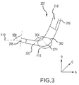
FIG. 3 illustrates a cross-sectional view of the ECS bleed port ofFIG. 2 , in accordance with various embodiments. - With reference to
FIG. 1 , agas turbine engine 20 is provided. An A-R-C axis shown in each of the figures illustrates the axial (A), radial (R) and circumferential (C) directions. As used herein, "aft" refers to the direction associated with the tail (e.g., the back end) of an aircraft, or generally, to the direction of exhaust of the gas turbine engine. As used herein, "forward" refers to the direction associated with the nose (e.g., the front end) of an aircraft, or generally, to the direction of flight or motion. As utilized herein, radially inward refers to the negative R direction and radially outward refers to the R direction. -
Gas turbine engine 20 can be a two-spool turbofan that generally incorporates afan section 22, acompressor section 24, acombustor section 26 and aturbine section 28. Alternative engines include an augmentor section among other systems or features. In operation,fan section 22 drives coolant along a bypass flow-path B whilecompressor section 24 drives coolant along a core flow-path C for compression and communication intocombustor section 26 then expansion throughturbine section 28. Although depicted as a turbofangas turbine engine 20 herein, it should be understood that the concepts described herein are not limited to use with turbofans as the teachings can be applied to other types of turbine engines including three-spool architectures. -
Gas turbine engine 20 generally comprise alow speed spool 30 and ahigh speed spool 32 mounted for rotation about an engine central longitudinal axis A-A' relative to an enginestatic structure 36 viaseveral bearing systems 38, 38-1, and 38-2. It should be understood thatvarious bearing systems 38 at various locations can alternatively or additionally be provided, including for example,bearing system 38, bearing system 38-1, and bearing system 38-2. -
Low speed spool 30 generally includes aninner shaft 40 that interconnects afan 42, a low pressure (or first)compressor section 44 and a low pressure (or first)turbine section 46.Inner shaft 40 is connected tofan 42 through a gearedarchitecture 48 that can drivefan 42 at a lower speed thanlow speed spool 30.Geared architecture 48 includes agear assembly 60 enclosed within agear housing 62.Gear assembly 60 couplesinner shaft 40 to a rotating fan structure.High speed spool 32 includes anouter shaft 50 that interconnects a high pressure (or second)compressor section 52 and high pressure (or second)turbine section 54. Acombustor 56 is located betweenhigh pressure compressor 52 andhigh pressure turbine 54. Amid-turbine frame 57 of enginestatic structure 36 is located generally betweenhigh pressure turbine 54 andlow pressure turbine 46.Mid-turbine frame 57 supports one or morebearing systems 38 inturbine section 28.Inner shaft 40 andouter shaft 50 are concentric and rotate viabearing systems 38 about the engine central longitudinal axis A-A', which is collinear with their longitudinal axes. As used herein, a "high pressure" compressor or turbine experiences a higher pressure than a corresponding "low pressure" compressor or turbine. - The core airflow D is compressed by low
pressure compressor section 44 thenhigh pressure compressor 52, mixed and burned with fuel incombustor 56, then expanded overhigh pressure turbine 54 andlow pressure turbine 46.Mid-turbine frame 57 includesairfoils 59 which are in the core airflow path.Turbines low speed spool 30 andhigh speed spool 32 in response to the expansion. -
Gas turbine engine 20 is a high-bypass geared aircraft engine. The bypass ratio ofgas turbine engine 20 can be greater than about six (6). The bypass ratio ofgas turbine engine 20 can also be greater than ten (10).Geared architecture 48 can be an epicyclic gear train, such as a star gear system (sun gear in meshing engagement with a plurality of star gears supported by a carrier and in meshing engagement with a ring gear) or other gear system.Geared architecture 48 can have a gear reduction ratio of greater than about 2.3 andlow pressure turbine 46 can have a pressure ratio that is greater than about five (5). The bypass ratio ofgas turbine engine 20 can be greater than about ten (10:1). The diameter offan 42 can be significantly greater than that of the lowpressure compressor section 44.Low pressure turbine 46 pressure ratio is measured prior to inlet oflow pressure turbine 46 as related to the pressure at the outlet oflow pressure turbine 46 prior to an exhaust nozzle. It should be understood, however, that the above parameters are exemplary of particular embodiments of a suitable geared architecture engine and that the present disclosure contemplates other turbine engines including direct drive turbofans. - The next generation of turbofan engines are designed for higher efficiency and use higher pressure ratios and higher temperatures in
high pressure compressor 52 than are conventionally experienced. These higher operating temperatures and pressure ratios create operating environments that cause thermal loads that are higher than the thermal loads conventionally experienced, which may shorten the operational life of current components. - With reference now to
FIGS 1 and.2 , airflow in lowpressure compressor section 44 is conditioned by one or more stators, including astator 202, and is compressed by one or more rotors, including arotor 200.Rotor 200 is the aft-most rotor of lowpressure compressor section 44. - A bleed
inlet 256 is defined by a lowpressure compressor case 262 and/or anintermediate case 265 and is positioned aft of theaft-most rotor 200 of lowpressure compressor section 44. Stated differently, bleedinlet 256 is downstream fromlow pressure compressor 44 and upstream fromhigh pressure compressor 52. Air received bybleed inlet 256 is received by ableed port 201. As air is compressed by lowpressure compressor section 44, the air is propelled aft such that the air flows towards highpressure compressor section 52 from lowpressure compressor section 44, as illustrated byarrow 204. A majority of the air flow labeled witharrow 211 is directed to highpressure compressor section 52, as illustrated byarrow 211. However, some of the air is received bybleed inlet 256, as illustrated byarrow 206 andarrow 208, and continues to flow throughbleed port 201. - Bleed
inlet 256 is defined between aforward point 264 and anaft point 212.Forward point 264 andaft point 212 are positioned betweenlow pressure compressor 44 andhigh pressure compressor 52.Forward point 264 is positioned radially outward fromaft point 212. Accordingly, bleedinlet 256 has anaxial component 295.Axial component 295 allows a predetermined amount of the air exiting lowpressure compressor section 44 to be received bybleed inlet 256, as the airflow has a larger axial component than radial or circumferential. - A
flow splitter 210 is positioned radially betweenforward point 264 andaft point 212. Anupstream inlet 271 is defined betweenforward point 264 and flowsplitter 210 and adownstream inlet 205 is defined betweenflow splitter 210 andaft point 212.Upstream inlet 271 is positioned radially outward fromdownstream inlet 205. Air received byupstream inlet 271 can flow through anupstream bleed channel 203, as illustrated byarrow 206, and air received bydownstream inlet 205 can be received by adownstream bleed channel 207, as illustrated byarrow 208.Downstream bleed channel 207 receives between 1 percent (1%) and 6 percent (6%) of the total airflow that exits lowpressure compressor section 44. -
Upstream bleed channel 203 is defined by an upstreamforward wall 280 extending radially outward and axially aft fromforward point 264 and an upstreamaft wall 282 extending radially outward and axially aft fromflow splitter 210. Avalve 254 is coupled toupstream bleed channel 203.Valve 254 can be adjusted to allow various percentages of the airflow received byupstream bleed channel 203 to exitgas turbine engine 20.Valve 254 is adjusted based on a power requested ofgas turbine engine 20. For example, as less power is requested ofgas turbine engine 20,valve 254 is increasingly opened. - In conventional systems, debris received by a gas turbine engine during takeoffs flow through the low pressure compressor section of the gas turbine engine. Due to the density of the debris particles being greater than the density of the air, after flowing through the last rotor of the low pressure compressor section, the debris particles are forced towards the outer diameter of the low pressure compressor section of the gas turbine engine. Accordingly, these debris particles are received by a stability bleed port and ejected from the aircraft.
Upstream bleed channel 203 functions in a similar manner and thus can be a stability bleed port. However, any debris flowing through the low pressure compressor section will not exit via the stability bleed port in response to the valve of a conventional gas turbine engine being closed. Accordingly, the debris can be received by the high pressure compressor section, where it can cause undesirable results. -
Downstream bleed channel 207 is defined by a downstream bleedforward wall 272 extending aft fromflow splitter 210 and a downstream bleed aftwall 274 extending aft fromaft point 212. Aft ofdownstream inlet 205, airflow fromdownstream bleed channel 207 is received by anair port 218 and adebris port 220 that are separated by aninner wall 270.Debris port 220 can receive between 0.1 % and 10% of the airflow flowing throughdownstream bleed channel 207 and the remaining air is received byair port 218. The airflow received byair port 218 can flow to an environmental control system, from which it can be provided to an aircraft cabin in order to pressurize and to provide fresh air to the cabin. Stated differently,downstream bleed channel 207 may be an environmental control system (ECS) port. -
Debris port 220 is designed such that it receives a majority of the debris received bydownstream bleed channel 207. The airflow received bydebris port 220 flows to an area external togas turbine engine 20. Thus, the debris received bydebris port 220 is ejected from the gas turbine engine. This reduces an amount of debris reaching highpressure compressor section 52 and entering the cabin, even in response tovalve 254 being closed. - Air entering
downstream bleed channel 207 can include an undesirable swirl component.Downstream bleed channel 207 includes anairfoil 217 having aleading edge 214 and a trailingedge 216.Airfoil 217 functions as a stator, conditioning the air flowing throughdownstream bleed channel 207. Conditioning the air can indicate a straightening of the airflow. This conditioning reduces the amount of swirl in the airflow. - It is desirable for the velocity of air flowing through
downstream bleed channel 207 to be reduced. Similarly, air enteringdownstream bleed channel 207 tends to have an undesirably high velocity.Airfoil 217 also functions as a diffuser for the airflow, resulting in a lowered velocity of the airflow. - A
forward diameter 258 ofdownstream bleed channel 207 is positioned nearerdownstream inlet 205 than anaft diameter 260 ofdownstream bleed channel 207 and is greater thanaft diameter 260. Because the diameter ofdownstream bleed channel 207 increases farther fromdownstream inlet 205, the airflow expands into the greater volume and loses velocity. - Downstream bleed
forward wall 272 can be an edge of a lowpressure compressor case 262 and Downstream bleed aftwall 274 can be an edge of anintermediate case 265.Airfoil 217 is coupled to Downstream bleedforward wall 272 and Downstream bleed aftwall 274 and can function as structural bridges between lowpressure compressor case 262 andintermediate case 265. Stated differently,airfoil 217 provides structural support between lowpressure compressor case 262 andintermediate case 265, resisting movement of lowpressure compressor case 262 relative tointermediate case 265 and resisting movement ofintermediate case 265 relative to lowpressure compressor case 262. - With reference now to
FIG. 3 ,downstream bleed channel 207 includes anaxial portion 300 and aradial portion 302.Axial portion 300 has a greater distance in the axial direction than the radial direction andradial portion 302 has a greater distance in the radial direction than the axial direction.Downstream bleed channel 207 includes acurved portion 312 betweenaxial portion 300 andradial portion 302.Curved portion 312 has anangle 304 that is between 30 degrees and 130 degrees. Stated differently,angle 304 betweenaxial portion 300 andradial portion 302 is between 30 degrees and 130 degrees. The curvature ofcurved portion 312 directs the airflow toward the ECS system. - The curvature of
curved portion 312 also directs the debris towarddebris port 220. As the debris has greater density than the air indownstream bleed channel 207, the debris will have a trajectory towards Downstream bleed aftwall 274. As a result of the curvature, as opposed to an angular transition betweenaxial portion 300 andradial portion 302, the debris will remain closer to Downstream bleed aftwall 274 than Downstream bleedforward wall 272. Accordingly, a majority of the debris is received bydebris port 220. - An
angle 306 is present betweendownstream inlet 205 and aline 310 parallel to the A axis.Downstream inlet 205 includes an axial component. Stated differently,angle 306 is between 45 degrees and 135 degrees. It is desirable for the ECS system to receive air of a certain pressure as this air is used to pressurize the cabin. Asdownstream inlet 205 includes an axial component, a majority of the total pressure of the air received bydownstream inlet 205 is retained. - Benefits, other advantages, and solutions to problems have been described herein with regard to specific embodiments. The scope of the disclosure, however, is provided in the appended claims.
Claims (15)
- A compressor section (24) of a gas turbine engine (20) comprising:a bleed port (201) having a flow splitter (210) therein so as to define a downstream bleed channel (207) having a downstream inlet (205) and an upstream bleed channel (203) having an upstream inlet (271) that is positioned radially outward from the downstream inlet (205).
- The compressor section of claim 1, wherein the downstream bleed channel (207) is an environmental control system (ECS) port, and optionally the upstream bleed channel (203) is a stability bleed port.
- The compressor section of claim 1 or 2, wherein the downstream bleed channel (207) receives between 1 percent and 6 percent of air propelled aft from a low pressure compressor section (44) of the compressor section (24).
- The compressor section of claim 1, 2 or 3, wherein the downstream inlet (205) is defined between an aft point (212) and the flow splitter (210) such that the flow splitter (210) is positioned axially aft of the aft point (212).
- The compressor section of any preceding claim, wherein the downstream bleed channel (207) further includes an axial portion (300), a radial portion (302) and a curved portion (312) such that an angle (304) between the axial portion (300) and the radial portion (302) is between 30 degrees and 130 degrees.
- The compressor section of any preceding claim, wherein the downstream bleed channel (207) is defined between a compressor edge of a low pressure compressor case (262) and an intermediate edge of an intermediate case (265).
- The compressor section of any preceding claim, further comprising an inner wall (270) positioned within the downstream bleed channel (207) defining a debris port (220) and an air port (218) wherein, optionally, the air port (218) is positioned axially forward of the debris port (220).
- The compressor section of any preceding claim, further comprising an airfoil (217) positioned within the downstream bleed channel (207) and configured to condition a flow of air.
- A gas turbine engine (20) comprising:a downstream bleed channel (207) having an inner wall (270) therein so as to define an air port (218) configured to receive a first flow and a debris port (220) configured to receive a second flow having more debris therein than the first flow.
- The gas turbine engine of claim 9, further comprising a bleed port (201) having a flow splitter (210) therein so as to define an upstream bleed channel (203) having an upstream inlet (271) and the downstream bleed channel (207) wherein, optionally. the downstream bleed channel (207) has a downstream inlet (205) being positioned radially inward from the upstream inlet (271).
- The gas turbine engine of claim 9 or 10, further comprising an airfoil (217) positioned within the downstream bleed channel (207) and configured to condition a flow of air.
- The gas turbine engine of claim 9, 10 or 11, wherein the downstream bleed channel (207) receives between 1 percent and 6 percent of air propelled aft from a low pressure compressor section (44) of the gas turbine engine (20).
- The gas turbine engine of any of claims 9 to 12, wherein the downstream bleed channel (207) is positioned downstream of a low pressure compressor section (44) of the gas turbine engine (20) and upstream of a high pressure compressor section (52) of the gas turbine engine (20), and/or the downstream bleed channel (207) includes an axial portion (300), a radial portion (302) and a curved portion (312) between the axial portion (300) and the radial portion (302).
- A compressor section (24) of a gas turbine engine (20) comprising:a bleed port (201) having a flow splitter (210) therein defining an upstream bleed channel (203) and a downstream bleed channel (207) having an axial portion (300), a radial portion (302) and a curved portion (312); andan inner wall (270) positioned within the downstream bleed channel (207) and defining a debris port (220) and an air port (218).
- The compressor section of claim 14, further comprising an airfoil (217) positioned within the downstream bleed channel (207) and configured to condition a flow of air, and/or wherein the bleed port (201) is positioned downstream from a low pressure compressor section (44) and upstream from a high pressure compressor section (52) of the compressor section (24).
Applications Claiming Priority (1)
| Application Number | Priority Date | Filing Date | Title |
|---|---|---|---|
| US14/706,748 US9909497B2 (en) | 2015-05-07 | 2015-05-07 | Combined stability and customer bleed with dirt, water and ice rejection |
Publications (2)
| Publication Number | Publication Date |
|---|---|
| EP3091210A1 true EP3091210A1 (en) | 2016-11-09 |
| EP3091210B1 EP3091210B1 (en) | 2018-07-04 |
Family
ID=55968924
Family Applications (1)
| Application Number | Title | Priority Date | Filing Date |
|---|---|---|---|
| EP16168495.6A Active EP3091210B1 (en) | 2015-05-07 | 2016-05-05 | Combined stability and customer bleed with dirt, water and ice rejection |
Country Status (2)
| Country | Link |
|---|---|
| US (1) | US9909497B2 (en) |
| EP (1) | EP3091210B1 (en) |
Cited By (3)
| Publication number | Priority date | Publication date | Assignee | Title |
|---|---|---|---|---|
| EP3398702A2 (en) * | 2017-05-02 | 2018-11-07 | Unison Industries LLC | Turbine engine duct |
| EP3643904A1 (en) * | 2018-10-24 | 2020-04-29 | United Technologies Corporation | Dirt mitigation in a gas turbine engine |
| FR3115326A1 (en) * | 2020-10-19 | 2022-04-22 | Safran | TURBOJET WITH IMPROVED AIR SAMPLING PERFORMANCE |
Families Citing this family (11)
| Publication number | Priority date | Publication date | Assignee | Title |
|---|---|---|---|---|
| FR3029895B1 (en) * | 2014-12-11 | 2017-01-13 | Technofan | FAN AND ASSOCIATED AIRCRAFT |
| US11434822B2 (en) * | 2015-06-19 | 2022-09-06 | Raytheon Technologies Corporation | Inverse modulation of secondary bleed |
| JP6689105B2 (en) * | 2016-03-14 | 2020-04-28 | 三菱重工業株式会社 | Multi-stage axial compressor and gas turbine |
| US10227930B2 (en) * | 2016-03-28 | 2019-03-12 | General Electric Company | Compressor bleed systems in turbomachines and methods of extracting compressor airflow |
| US20180149092A1 (en) * | 2016-11-30 | 2018-05-31 | Rolls-Royce North American Technologies, Inc. | Control technologies for turbine engine with integrated inlet particle separator and infrared suppression system |
| US11261800B2 (en) | 2018-10-24 | 2022-03-01 | Raytheon Technologies Corporation | Adaptive bleed schedule in a gas turbine engine |
| RU2732188C1 (en) * | 2020-02-13 | 2020-09-14 | Акционерное общество "ТУРБОХОЛОД" | Turbo-expander assembly |
| US11713722B2 (en) * | 2020-05-08 | 2023-08-01 | Rolls-Royce Corporation | Gas turbine engine compressor particulate offtake |
| US12454911B2 (en) | 2023-12-29 | 2025-10-28 | Rtx Corporation | Bleeding core air from a turbine engine core flowpath |
| US12180898B1 (en) * | 2023-12-29 | 2024-12-31 | Rtx Corporation | Regulating core air bled from a turbine engine core flowpath |
| US12546261B1 (en) | 2025-03-25 | 2026-02-10 | Rolls-Royce North American Technologies Inc. | Compressor bleed air collector and exhaust ducting for gas turbine engine systems |
Citations (4)
| Publication number | Priority date | Publication date | Assignee | Title |
|---|---|---|---|---|
| US20070137175A1 (en) * | 2005-12-21 | 2007-06-21 | General Electric Company | Compact booster bleed turbofan |
| EP2431590A2 (en) * | 2010-09-21 | 2012-03-21 | United Technologies Corporation | Gas turbine engine with bleed duct for minimum reduction of bleed flow and minimum rejection of hail during hail ingestion events |
| WO2014092778A1 (en) * | 2012-12-10 | 2014-06-19 | United Technologies Corporation | Dual filtration particle separator |
| US20140245747A1 (en) * | 2012-10-12 | 2014-09-04 | General Electric Company | Gas turbine engine two degree of freedom variable bleed valve for ice extraction |
Family Cites Families (6)
| Publication number | Priority date | Publication date | Assignee | Title |
|---|---|---|---|---|
| US4463552A (en) * | 1981-12-14 | 1984-08-07 | United Technologies Corporation | Combined surge bleed and dust removal system for a fan-jet engine |
| US5155993A (en) * | 1990-04-09 | 1992-10-20 | General Electric Company | Apparatus for compressor air extraction |
| US6325595B1 (en) * | 2000-03-24 | 2001-12-04 | General Electric Company | High recovery multi-use bleed |
| WO2006091138A1 (en) * | 2005-02-25 | 2006-08-31 | Volvo Aero Corporation | A bleed structure for a bleed passage in a gas turbine engine |
| US9982598B2 (en) * | 2012-10-22 | 2018-05-29 | General Electric Company | Gas turbine engine variable bleed valve for ice extraction |
| FR3019855B1 (en) * | 2014-04-14 | 2016-04-01 | Airbus Operations Sas | AIRCRAFT PROPULSIVE ASSEMBLY COMPRISING A VARIABLE FLOW AIR VALVE |
-
2015
- 2015-05-07 US US14/706,748 patent/US9909497B2/en active Active
-
2016
- 2016-05-05 EP EP16168495.6A patent/EP3091210B1/en active Active
Patent Citations (4)
| Publication number | Priority date | Publication date | Assignee | Title |
|---|---|---|---|---|
| US20070137175A1 (en) * | 2005-12-21 | 2007-06-21 | General Electric Company | Compact booster bleed turbofan |
| EP2431590A2 (en) * | 2010-09-21 | 2012-03-21 | United Technologies Corporation | Gas turbine engine with bleed duct for minimum reduction of bleed flow and minimum rejection of hail during hail ingestion events |
| US20140245747A1 (en) * | 2012-10-12 | 2014-09-04 | General Electric Company | Gas turbine engine two degree of freedom variable bleed valve for ice extraction |
| WO2014092778A1 (en) * | 2012-12-10 | 2014-06-19 | United Technologies Corporation | Dual filtration particle separator |
Cited By (6)
| Publication number | Priority date | Publication date | Assignee | Title |
|---|---|---|---|---|
| EP3398702A2 (en) * | 2017-05-02 | 2018-11-07 | Unison Industries LLC | Turbine engine duct |
| EP3398702B1 (en) * | 2017-05-02 | 2025-07-23 | Unison Industries LLC | Turbine engine duct |
| EP3643904A1 (en) * | 2018-10-24 | 2020-04-29 | United Technologies Corporation | Dirt mitigation in a gas turbine engine |
| FR3115326A1 (en) * | 2020-10-19 | 2022-04-22 | Safran | TURBOJET WITH IMPROVED AIR SAMPLING PERFORMANCE |
| WO2022084614A1 (en) * | 2020-10-19 | 2022-04-28 | Safran | Turbojet engine with improved air collection performance |
| US12352205B2 (en) | 2020-10-19 | 2025-07-08 | Safran | Turbojet with improved air extraction performance |
Also Published As
| Publication number | Publication date |
|---|---|
| EP3091210B1 (en) | 2018-07-04 |
| US9909497B2 (en) | 2018-03-06 |
| US20160326957A1 (en) | 2016-11-10 |
Similar Documents
| Publication | Publication Date | Title |
|---|---|---|
| EP3091210B1 (en) | Combined stability and customer bleed with dirt, water and ice rejection | |
| US11859538B2 (en) | Geared turbofan engine with targeted modular efficiency | |
| US9506422B2 (en) | Efficient, low pressure ratio propulsor for gas turbine engines | |
| US20230383699A1 (en) | Gas turbine engine with power density range | |
| US9121412B2 (en) | Efficient, low pressure ratio propulsor for gas turbine engines | |
| US10724440B2 (en) | Compressor injector apparatus and system | |
| US20180106274A1 (en) | Gas turbine engine | |
| EP3088670A1 (en) | Film cooled component and corresponding film cooling system | |
| CN109196187B (en) | Method and system for a two frame gas turbine engine | |
| US20110150633A1 (en) | Intermediate fan stage | |
| US10006371B2 (en) | Film hole with in-wall accumulator | |
| US10330017B2 (en) | Three spool geared turbofan with low pressure compressor drive gear system | |
| US20110150627A1 (en) | Method of operating a fan system | |
| CN112459922A (en) | Efficient injection | |
| CN213574368U (en) | Gas turbine engine for aircraft | |
| US20170342839A1 (en) | System for a low swirl low pressure turbine | |
| WO2015126452A1 (en) | Gas turbine engine airfoil | |
| US20140212261A1 (en) | Lightweight shrouded fan | |
| CN112459923B (en) | Turbofan core and bypass arrangement | |
| US10961854B2 (en) | Dirt funnel squealer purges | |
| EP3108103A1 (en) | Gas turbine engine airfoil |
Legal Events
| Date | Code | Title | Description |
|---|---|---|---|
| PUAI | Public reference made under article 153(3) epc to a published international application that has entered the european phase |
Free format text: ORIGINAL CODE: 0009012 |
|
| AK | Designated contracting states |
Kind code of ref document: A1 Designated state(s): AL AT BE BG CH CY CZ DE DK EE ES FI FR GB GR HR HU IE IS IT LI LT LU LV MC MK MT NL NO PL PT RO RS SE SI SK SM TR |
|
| AX | Request for extension of the european patent |
Extension state: BA ME |
|
| STAA | Information on the status of an ep patent application or granted ep patent |
Free format text: STATUS: REQUEST FOR EXAMINATION WAS MADE |
|
| 17P | Request for examination filed |
Effective date: 20170509 |
|
| RBV | Designated contracting states (corrected) |
Designated state(s): AL AT BE BG CH CY CZ DE DK EE ES FI FR GB GR HR HU IE IS IT LI LT LU LV MC MK MT NL NO PL PT RO RS SE SI SK SM TR |
|
| GRAP | Despatch of communication of intention to grant a patent |
Free format text: ORIGINAL CODE: EPIDOSNIGR1 |
|
| STAA | Information on the status of an ep patent application or granted ep patent |
Free format text: STATUS: GRANT OF PATENT IS INTENDED |
|
| INTG | Intention to grant announced |
Effective date: 20171218 |
|
| GRAS | Grant fee paid |
Free format text: ORIGINAL CODE: EPIDOSNIGR3 |
|
| GRAA | (expected) grant |
Free format text: ORIGINAL CODE: 0009210 |
|
| STAA | Information on the status of an ep patent application or granted ep patent |
Free format text: STATUS: THE PATENT HAS BEEN GRANTED |
|
| AK | Designated contracting states |
Kind code of ref document: B1 Designated state(s): AL AT BE BG CH CY CZ DE DK EE ES FI FR GB GR HR HU IE IS IT LI LT LU LV MC MK MT NL NO PL PT RO RS SE SI SK SM TR |
|
| REG | Reference to a national code |
Ref country code: GB Ref legal event code: FG4D |
|
| REG | Reference to a national code |
Ref country code: CH Ref legal event code: EP |
|
| REG | Reference to a national code |
Ref country code: AT Ref legal event code: REF Ref document number: 1014755 Country of ref document: AT Kind code of ref document: T Effective date: 20180715 |
|
| REG | Reference to a national code |
Ref country code: IE Ref legal event code: FG4D |
|
| REG | Reference to a national code |
Ref country code: DE Ref legal event code: R096 Ref document number: 602016003906 Country of ref document: DE |
|
| REG | Reference to a national code |
Ref country code: NL Ref legal event code: MP Effective date: 20180704 |
|
| REG | Reference to a national code |
Ref country code: LT Ref legal event code: MG4D |
|
| REG | Reference to a national code |
Ref country code: AT Ref legal event code: MK05 Ref document number: 1014755 Country of ref document: AT Kind code of ref document: T Effective date: 20180704 |
|
| PG25 | Lapsed in a contracting state [announced via postgrant information from national office to epo] |
Ref country code: NL Free format text: LAPSE BECAUSE OF FAILURE TO SUBMIT A TRANSLATION OF THE DESCRIPTION OR TO PAY THE FEE WITHIN THE PRESCRIBED TIME-LIMIT Effective date: 20180704 |
|
| PG25 | Lapsed in a contracting state [announced via postgrant information from national office to epo] |
Ref country code: CZ Free format text: LAPSE BECAUSE OF FAILURE TO SUBMIT A TRANSLATION OF THE DESCRIPTION OR TO PAY THE FEE WITHIN THE PRESCRIBED TIME-LIMIT Effective date: 20180704 Ref country code: LT Free format text: LAPSE BECAUSE OF FAILURE TO SUBMIT A TRANSLATION OF THE DESCRIPTION OR TO PAY THE FEE WITHIN THE PRESCRIBED TIME-LIMIT Effective date: 20180704 Ref country code: IS Free format text: LAPSE BECAUSE OF FAILURE TO SUBMIT A TRANSLATION OF THE DESCRIPTION OR TO PAY THE FEE WITHIN THE PRESCRIBED TIME-LIMIT Effective date: 20181104 Ref country code: AT Free format text: LAPSE BECAUSE OF FAILURE TO SUBMIT A TRANSLATION OF THE DESCRIPTION OR TO PAY THE FEE WITHIN THE PRESCRIBED TIME-LIMIT Effective date: 20180704 Ref country code: PL Free format text: LAPSE BECAUSE OF FAILURE TO SUBMIT A TRANSLATION OF THE DESCRIPTION OR TO PAY THE FEE WITHIN THE PRESCRIBED TIME-LIMIT Effective date: 20180704 Ref country code: SE Free format text: LAPSE BECAUSE OF FAILURE TO SUBMIT A TRANSLATION OF THE DESCRIPTION OR TO PAY THE FEE WITHIN THE PRESCRIBED TIME-LIMIT Effective date: 20180704 Ref country code: BG Free format text: LAPSE BECAUSE OF FAILURE TO SUBMIT A TRANSLATION OF THE DESCRIPTION OR TO PAY THE FEE WITHIN THE PRESCRIBED TIME-LIMIT Effective date: 20181004 Ref country code: FI Free format text: LAPSE BECAUSE OF FAILURE TO SUBMIT A TRANSLATION OF THE DESCRIPTION OR TO PAY THE FEE WITHIN THE PRESCRIBED TIME-LIMIT Effective date: 20180704 Ref country code: NO Free format text: LAPSE BECAUSE OF FAILURE TO SUBMIT A TRANSLATION OF THE DESCRIPTION OR TO PAY THE FEE WITHIN THE PRESCRIBED TIME-LIMIT Effective date: 20181004 Ref country code: RS Free format text: LAPSE BECAUSE OF FAILURE TO SUBMIT A TRANSLATION OF THE DESCRIPTION OR TO PAY THE FEE WITHIN THE PRESCRIBED TIME-LIMIT Effective date: 20180704 Ref country code: GR Free format text: LAPSE BECAUSE OF FAILURE TO SUBMIT A TRANSLATION OF THE DESCRIPTION OR TO PAY THE FEE WITHIN THE PRESCRIBED TIME-LIMIT Effective date: 20181005 |
|
| PG25 | Lapsed in a contracting state [announced via postgrant information from national office to epo] |
Ref country code: ES Free format text: LAPSE BECAUSE OF FAILURE TO SUBMIT A TRANSLATION OF THE DESCRIPTION OR TO PAY THE FEE WITHIN THE PRESCRIBED TIME-LIMIT Effective date: 20180704 Ref country code: HR Free format text: LAPSE BECAUSE OF FAILURE TO SUBMIT A TRANSLATION OF THE DESCRIPTION OR TO PAY THE FEE WITHIN THE PRESCRIBED TIME-LIMIT Effective date: 20180704 Ref country code: LV Free format text: LAPSE BECAUSE OF FAILURE TO SUBMIT A TRANSLATION OF THE DESCRIPTION OR TO PAY THE FEE WITHIN THE PRESCRIBED TIME-LIMIT Effective date: 20180704 Ref country code: AL Free format text: LAPSE BECAUSE OF FAILURE TO SUBMIT A TRANSLATION OF THE DESCRIPTION OR TO PAY THE FEE WITHIN THE PRESCRIBED TIME-LIMIT Effective date: 20180704 |
|
| REG | Reference to a national code |
Ref country code: DE Ref legal event code: R097 Ref document number: 602016003906 Country of ref document: DE |
|
| PG25 | Lapsed in a contracting state [announced via postgrant information from national office to epo] |
Ref country code: EE Free format text: LAPSE BECAUSE OF FAILURE TO SUBMIT A TRANSLATION OF THE DESCRIPTION OR TO PAY THE FEE WITHIN THE PRESCRIBED TIME-LIMIT Effective date: 20180704 Ref country code: IT Free format text: LAPSE BECAUSE OF FAILURE TO SUBMIT A TRANSLATION OF THE DESCRIPTION OR TO PAY THE FEE WITHIN THE PRESCRIBED TIME-LIMIT Effective date: 20180704 Ref country code: RO Free format text: LAPSE BECAUSE OF FAILURE TO SUBMIT A TRANSLATION OF THE DESCRIPTION OR TO PAY THE FEE WITHIN THE PRESCRIBED TIME-LIMIT Effective date: 20180704 |
|
| PLBE | No opposition filed within time limit |
Free format text: ORIGINAL CODE: 0009261 |
|
| STAA | Information on the status of an ep patent application or granted ep patent |
Free format text: STATUS: NO OPPOSITION FILED WITHIN TIME LIMIT |
|
| PG25 | Lapsed in a contracting state [announced via postgrant information from national office to epo] |
Ref country code: SM Free format text: LAPSE BECAUSE OF FAILURE TO SUBMIT A TRANSLATION OF THE DESCRIPTION OR TO PAY THE FEE WITHIN THE PRESCRIBED TIME-LIMIT Effective date: 20180704 Ref country code: SK Free format text: LAPSE BECAUSE OF FAILURE TO SUBMIT A TRANSLATION OF THE DESCRIPTION OR TO PAY THE FEE WITHIN THE PRESCRIBED TIME-LIMIT Effective date: 20180704 Ref country code: DK Free format text: LAPSE BECAUSE OF FAILURE TO SUBMIT A TRANSLATION OF THE DESCRIPTION OR TO PAY THE FEE WITHIN THE PRESCRIBED TIME-LIMIT Effective date: 20180704 |
|
| 26N | No opposition filed |
Effective date: 20190405 |
|
| PG25 | Lapsed in a contracting state [announced via postgrant information from national office to epo] |
Ref country code: SI Free format text: LAPSE BECAUSE OF FAILURE TO SUBMIT A TRANSLATION OF THE DESCRIPTION OR TO PAY THE FEE WITHIN THE PRESCRIBED TIME-LIMIT Effective date: 20180704 |
|
| REG | Reference to a national code |
Ref country code: CH Ref legal event code: PL |
|
| PG25 | Lapsed in a contracting state [announced via postgrant information from national office to epo] |
Ref country code: LI Free format text: LAPSE BECAUSE OF NON-PAYMENT OF DUE FEES Effective date: 20190531 Ref country code: MC Free format text: LAPSE BECAUSE OF FAILURE TO SUBMIT A TRANSLATION OF THE DESCRIPTION OR TO PAY THE FEE WITHIN THE PRESCRIBED TIME-LIMIT Effective date: 20180704 Ref country code: CH Free format text: LAPSE BECAUSE OF NON-PAYMENT OF DUE FEES Effective date: 20190531 |
|
| REG | Reference to a national code |
Ref country code: BE Ref legal event code: MM Effective date: 20190531 |
|
| PG25 | Lapsed in a contracting state [announced via postgrant information from national office to epo] |
Ref country code: LU Free format text: LAPSE BECAUSE OF NON-PAYMENT OF DUE FEES Effective date: 20190505 |
|
| PG25 | Lapsed in a contracting state [announced via postgrant information from national office to epo] |
Ref country code: TR Free format text: LAPSE BECAUSE OF FAILURE TO SUBMIT A TRANSLATION OF THE DESCRIPTION OR TO PAY THE FEE WITHIN THE PRESCRIBED TIME-LIMIT Effective date: 20180704 |
|
| PG25 | Lapsed in a contracting state [announced via postgrant information from national office to epo] |
Ref country code: IE Free format text: LAPSE BECAUSE OF NON-PAYMENT OF DUE FEES Effective date: 20190505 |
|
| PG25 | Lapsed in a contracting state [announced via postgrant information from national office to epo] |
Ref country code: BE Free format text: LAPSE BECAUSE OF NON-PAYMENT OF DUE FEES Effective date: 20190531 |
|
| PG25 | Lapsed in a contracting state [announced via postgrant information from national office to epo] |
Ref country code: PT Free format text: LAPSE BECAUSE OF FAILURE TO SUBMIT A TRANSLATION OF THE DESCRIPTION OR TO PAY THE FEE WITHIN THE PRESCRIBED TIME-LIMIT Effective date: 20181104 |
|
| PG25 | Lapsed in a contracting state [announced via postgrant information from national office to epo] |
Ref country code: CY Free format text: LAPSE BECAUSE OF FAILURE TO SUBMIT A TRANSLATION OF THE DESCRIPTION OR TO PAY THE FEE WITHIN THE PRESCRIBED TIME-LIMIT Effective date: 20180704 |
|
| PG25 | Lapsed in a contracting state [announced via postgrant information from national office to epo] |
Ref country code: MT Free format text: LAPSE BECAUSE OF FAILURE TO SUBMIT A TRANSLATION OF THE DESCRIPTION OR TO PAY THE FEE WITHIN THE PRESCRIBED TIME-LIMIT Effective date: 20180704 Ref country code: HU Free format text: LAPSE BECAUSE OF FAILURE TO SUBMIT A TRANSLATION OF THE DESCRIPTION OR TO PAY THE FEE WITHIN THE PRESCRIBED TIME-LIMIT; INVALID AB INITIO Effective date: 20160505 |
|
| PG25 | Lapsed in a contracting state [announced via postgrant information from national office to epo] |
Ref country code: MK Free format text: LAPSE BECAUSE OF FAILURE TO SUBMIT A TRANSLATION OF THE DESCRIPTION OR TO PAY THE FEE WITHIN THE PRESCRIBED TIME-LIMIT Effective date: 20180704 |
|
| REG | Reference to a national code |
Ref country code: DE Ref legal event code: R081 Ref document number: 602016003906 Country of ref document: DE Owner name: RAYTHEON TECHNOLOGIES CORPORATION (N.D.GES.D.S, US Free format text: FORMER OWNER: UNITED TECHNOLOGIES CORPORATION, FARMINGTON, CONN., US Ref country code: DE Ref legal event code: R081 Ref document number: 602016003906 Country of ref document: DE Owner name: RTX CORPORATION (N.D.GES.D. STAATES DELAWARE),, US Free format text: FORMER OWNER: UNITED TECHNOLOGIES CORPORATION, FARMINGTON, CONN., US |
|
| P01 | Opt-out of the competence of the unified patent court (upc) registered |
Effective date: 20230520 |
|
| PGFP | Annual fee paid to national office [announced via postgrant information from national office to epo] |
Ref country code: DE Payment date: 20250423 Year of fee payment: 10 |
|
| PGFP | Annual fee paid to national office [announced via postgrant information from national office to epo] |
Ref country code: GB Payment date: 20250423 Year of fee payment: 10 |
|
| PGFP | Annual fee paid to national office [announced via postgrant information from national office to epo] |
Ref country code: FR Payment date: 20250423 Year of fee payment: 10 |
|
| REG | Reference to a national code |
Ref country code: DE Ref legal event code: R081 Ref document number: 602016003906 Country of ref document: DE Owner name: RTX CORPORATION (N.D.GES.D. STAATES DELAWARE),, US Free format text: FORMER OWNER: RAYTHEON TECHNOLOGIES CORPORATION (N.D.GES.D.STAATES DELAWARE), ARLINGTON, VA, US |