EP3091192A1 - Blade outer air seals with channels - Google Patents
Blade outer air seals with channels Download PDFInfo
- Publication number
- EP3091192A1 EP3091192A1 EP16158754.8A EP16158754A EP3091192A1 EP 3091192 A1 EP3091192 A1 EP 3091192A1 EP 16158754 A EP16158754 A EP 16158754A EP 3091192 A1 EP3091192 A1 EP 3091192A1
- Authority
- EP
- European Patent Office
- Prior art keywords
- boas
- outlet
- thermal regulation
- inlet
- aft
- Prior art date
- Legal status (The legal status is an assumption and is not a legal conclusion. Google has not performed a legal analysis and makes no representation as to the accuracy of the status listed.)
- Granted
Links
Images
Classifications
-
- F—MECHANICAL ENGINEERING; LIGHTING; HEATING; WEAPONS; BLASTING
- F01—MACHINES OR ENGINES IN GENERAL; ENGINE PLANTS IN GENERAL; STEAM ENGINES
- F01D—NON-POSITIVE DISPLACEMENT MACHINES OR ENGINES, e.g. STEAM TURBINES
- F01D25/00—Component parts, details, or accessories, not provided for in, or of interest apart from, other groups
- F01D25/08—Cooling; Heating; Heat-insulation
- F01D25/12—Cooling
-
- F—MECHANICAL ENGINEERING; LIGHTING; HEATING; WEAPONS; BLASTING
- F01—MACHINES OR ENGINES IN GENERAL; ENGINE PLANTS IN GENERAL; STEAM ENGINES
- F01D—NON-POSITIVE DISPLACEMENT MACHINES OR ENGINES, e.g. STEAM TURBINES
- F01D11/00—Preventing or minimising internal leakage of working-fluid, e.g. between stages
- F01D11/08—Preventing or minimising internal leakage of working-fluid, e.g. between stages for sealing space between rotor blade tips and stator
-
- F—MECHANICAL ENGINEERING; LIGHTING; HEATING; WEAPONS; BLASTING
- F01—MACHINES OR ENGINES IN GENERAL; ENGINE PLANTS IN GENERAL; STEAM ENGINES
- F01D—NON-POSITIVE DISPLACEMENT MACHINES OR ENGINES, e.g. STEAM TURBINES
- F01D5/00—Blades; Blade-carrying members; Heating, heat-insulating, cooling or antivibration means on the blades or the members
- F01D5/12—Blades
- F01D5/14—Form or construction
- F01D5/18—Hollow blades, i.e. blades with cooling or heating channels or cavities; Heating, heat-insulating or cooling means on blades
- F01D5/187—Convection cooling
-
- F—MECHANICAL ENGINEERING; LIGHTING; HEATING; WEAPONS; BLASTING
- F05—INDEXING SCHEMES RELATING TO ENGINES OR PUMPS IN VARIOUS SUBCLASSES OF CLASSES F01-F04
- F05D—INDEXING SCHEME FOR ASPECTS RELATING TO NON-POSITIVE-DISPLACEMENT MACHINES OR ENGINES, GAS-TURBINES OR JET-PROPULSION PLANTS
- F05D2220/00—Application
- F05D2220/30—Application in turbines
- F05D2220/32—Application in turbines in gas turbines
-
- F—MECHANICAL ENGINEERING; LIGHTING; HEATING; WEAPONS; BLASTING
- F05—INDEXING SCHEMES RELATING TO ENGINES OR PUMPS IN VARIOUS SUBCLASSES OF CLASSES F01-F04
- F05D—INDEXING SCHEME FOR ASPECTS RELATING TO NON-POSITIVE-DISPLACEMENT MACHINES OR ENGINES, GAS-TURBINES OR JET-PROPULSION PLANTS
- F05D2230/00—Manufacture
- F05D2230/10—Manufacture by removing material
-
- F—MECHANICAL ENGINEERING; LIGHTING; HEATING; WEAPONS; BLASTING
- F05—INDEXING SCHEMES RELATING TO ENGINES OR PUMPS IN VARIOUS SUBCLASSES OF CLASSES F01-F04
- F05D—INDEXING SCHEME FOR ASPECTS RELATING TO NON-POSITIVE-DISPLACEMENT MACHINES OR ENGINES, GAS-TURBINES OR JET-PROPULSION PLANTS
- F05D2240/00—Components
- F05D2240/10—Stators
- F05D2240/11—Shroud seal segments
-
- F—MECHANICAL ENGINEERING; LIGHTING; HEATING; WEAPONS; BLASTING
- F05—INDEXING SCHEMES RELATING TO ENGINES OR PUMPS IN VARIOUS SUBCLASSES OF CLASSES F01-F04
- F05D—INDEXING SCHEME FOR ASPECTS RELATING TO NON-POSITIVE-DISPLACEMENT MACHINES OR ENGINES, GAS-TURBINES OR JET-PROPULSION PLANTS
- F05D2260/00—Function
- F05D2260/20—Heat transfer, e.g. cooling
-
- Y—GENERAL TAGGING OF NEW TECHNOLOGICAL DEVELOPMENTS; GENERAL TAGGING OF CROSS-SECTIONAL TECHNOLOGIES SPANNING OVER SEVERAL SECTIONS OF THE IPC; TECHNICAL SUBJECTS COVERED BY FORMER USPC CROSS-REFERENCE ART COLLECTIONS [XRACs] AND DIGESTS
- Y02—TECHNOLOGIES OR APPLICATIONS FOR MITIGATION OR ADAPTATION AGAINST CLIMATE CHANGE
- Y02T—CLIMATE CHANGE MITIGATION TECHNOLOGIES RELATED TO TRANSPORTATION
- Y02T50/00—Aeronautics or air transport
- Y02T50/60—Efficient propulsion technologies, e.g. for aircraft
Definitions
- the present disclosure relates to blade outer air seals, more specifically to thermal regulation channels defined in blade outer air seals.
- BOAS blade outer air seals
- Traditional blade outer air seals include radial inlet holes near a leading edge portion thereof to allow cooling flow to be fed to a core of the BOAS for cooling.
- certain BOAS are positioned in the turbomachine in communication with a double-axial brush seal that prevents feeding the core of the BOAS with radial inlet holes because the traditional radial inlet holes are blocked by the brush seal.
- Traditional ceramic core designs have used overpass features to supply cooling air to the forward most core portions, however, such solutions may not be feasible with certain core designs.
- a blade outer air seal includes a body defining a core having a forward cavity portion and a plurality of forward hooks extending radially from the body, the hooks extending to a hook height.
- the BOAS includes a seal surface defined between the forward hooks and which includes a forward side, an aft side, and a seal surface height.
- the seal surface is aft of the forward cavity portion.
- the BOAS includes a thermal regulation channel defining an inlet aft of the sealing surface and an outlet defined in fluid communication with the forward cavity portion.
- the thermal regulation channel can be defined at an angle from the inlet to the outlet relative to a radial direction.
- the inlet can be defined in the aft side of the seal surface.
- the outlet can be defined at least partially forward of the forward side of the seal surface.
- the BOAS can further include a plurality of side outlets in fluid communication with the forward cavity portion to allow flow to effuse from a side of the BOAS and into a gas path.
- the BOAS can include one or more flow guides and/or posts disposed between the outlet of the thermal regulation channel and the side outlets.
- the inlet can be a first inlet
- the outlet can be a first outlet
- the BOAS can further include a second thermal regulation channel defining a second inlet aft of the sealing surface and a second outlet defined in fluid communication with the forward cavity portion.
- the first outlet can be separated from the second outlet by a divider disposed within the forward cavity.
- a turbomachine can include a BOAS as described above.
- a method can include disposing a thermal regulation channel in a BOAS body such that the thermal regulation channel defines an inlet aft of a sealing surface of the BOAS and an outlet defined in fluid communication with a forward cavity portion defined by the BOAS body. Disposing the thermal regulation channel can include at least one of drilling the channel through the BOAS body or forming the BOAS body to include the thermal regulation channel.
- a blade outer air seal comprising: a body defining a core, the core including a forward cavity portion; a plurality of forward hooks extending radially from the body, the hooks extending to a hook height; a seal surface defined between the forward hooks, the seal surface including a forward side, an aft side, and a seal surface height, wherein the seal surface is aft of the forward cavity portion; and a thermal regulation channel defining an inlet aft of the sealing surface and an outlet defined in fluid communication with the forward cavity portion.
- BOAS blade outer air seal
- the thermal regulation channel is defined at an angle from the inlet to the outlet relative to a radial direction.
- the inlet is defined in the aft side of the seal surface.
- the outlet is defined at least partially forward of the forward side of the seal surface.
- a plurality of side outlets in fluid communication with the forward cavity portion to allow flow to effuse from a side of the BOAS and into a gas path.
- one or more flow guides disposed between the outlet of the thermal regulation channel and the side outlets.
- one or more posts disposed between the outlet of the thermal regulation channel and the side outlets.
- the inlet is a first inlet
- the outlet is a first outlet
- the BOAS further comprises a second thermal regulation channel defining a second inlet aft of the sealing surface and a second outlet defined in fluid communication with the forward cavity portion.
- the first outlet is separated from the second outlet by a divider disposed within the forward cavity.
- a turbomachine comprising: a blade outer air seal (BOAS), the BOAS including: a body defining a core, the core including a forward cavity portion; a plurality of forward hooks extending radially from the body, the hooks extending to a hook height; a seal surface defined between the forward hooks, the seal surface including a forward side, an aft side, and a seal surface height, wherein the seal surface is aft of the forward cavity portion; and a thermal regulation channel defining an inlet aft of the sealing surface and an outlet defined in fluid communication with the forward cavity portion.
- BOAS blade outer air seal
- the thermal regulation channel is defined at an angle from the inlet to the outlet relative to a radial direction.
- the inlet is defined in the aft side of the seal surface.
- the outlet is defined at least partially forward of the forward side of the seal surface.
- a plurality of side outlets in fluid communication with the forward cavity portion to allow flow to effuse from a side of the BOAS and into a gas path.
- one or more flow guides disposed between the outlet of the thermal regulation channel and the side outlets.
- one or more posts disposed between the outlet of the thermal regulation channel and the side outlets.
- the inlet is a first inlet
- the outlet is a first outlet
- the BOAS further comprises a second thermal regulation channel defining a second inlet aft of the sealing surface and a second outlet defined in fluid communication with the forward cavity portion.
- the first outlet is separated from the second outlet by a divider disposed within the forward cavity.
- a method comprising: disposing a thermal regulation channel in a blade outer air seal (BOAS) body such that the thermal regulation channel defines an inlet aft of a sealing surface of the BOAS and an outlet defined in fluid communication with a forward cavity portion defined by the BOAS body.
- BOAS blade outer air seal
- disposing the thermal regulation channel includes at least one of drilling the channel through the BOAS body or forming the BOAS body to include the thermal regulation channel.
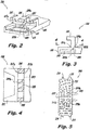
- FIG. 2 an illustrative view of an embodiment of a blade outer air seal (BOAS) 200 in accordance with the disclosure is shown in Fig. 2 and is designated generally by reference character 200.
- FIGs. 3-5 Other embodiments and/or aspects of this disclosure are shown in Figs. 3-5 .
- the systems and methods described herein can be used to provide cooling flow to a forward cavity portion of a BOAS from an aft location.
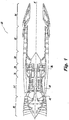
- Fig. 1 schematically illustrates a gas turbine engine 20.
- the gas turbine engine 20 is disclosed herein as a two-spool low-bypass augmented turbofan that generally incorporates a fan section 22, a compressor section 24, a combustor section 26, a turbine section 28, an augmenter section 30, an exhaust duct section 32, and a nozzle system 34 along a central longitudinal engine axis A.
- augmented low bypass turbofan depicted as an augmented low bypass turbofan in the disclosed nonlimiting embodiment, it should be understood that the concepts described herein are applicable to other gas turbine engines including non-augmented engines, geared architecture engines, direct drive turbofans, turbojet, turboshaft, multi-stream variable cycle adaptive engines and other engine architectures.
- Variable cycle gas turbine engines power aircraft over a range of operating conditions and essentially alters a bypass ratio during flight to achieve countervailing objectives such as high specific thrust for high-energy maneuvers yet optimizes fuel efficiency for cruise and loiter operational modes.
- An engine case structure 36 defines a generally annular secondary airflow path 40 around a core airflow path 42. It should be appreciated that various components, individually and collectively, may define the engine case structure 36 that essentially defines an exoskeleton to support the rotational hardware.
- Air that enters the fan section 22 is divided between a core airflow through the core airflow path 42 and a secondary airflow through a secondary airflow path 40.
- the core airflow passes through the combustor section 26, the turbine section 28, then the augmentor section 30 where fuel may be selectively injected and burned to generate additional thrust through the nozzle system 34.
- additional airflow streams such as third stream airflow typical of variable cycle engine architectures may additionally be sourced from the fan section 22.
- the secondary airflow may be utilized for a multiple of purposes to include, for example, cooling and pressurization.
- the secondary airflow as defined herein may be any airflow different from the core airflow.
- the secondary airflow may ultimately be at least partially injected into the core airflow path 42 adjacent to the exhaust duct section 32 and the nozzle system 34.
- the exhaust duct section 32 may be circular in cross-section as typical of an axisymmetric augmented low bypass turbofan or may be non-axisymmetric in cross-section to include, but not be limited to, a serpentine shape to block direct view to the turbine section 28.
- the exhaust duct section 32 may terminate in a Convergent/Divergent (C/D) nozzle system, a non-axisymmetric two-dimensional (2D) C/D vectorable nozzle system, a flattened slot nozzle of high aspect ratio or other nozzle arrangement.
- C/D Convergent/Divergent
- 2D non-axisymmetric two-dimensional
- a blade outer air seal (BOAS) 200 includes a body 201 defining a core having a forward cavity portion 203 and a plurality of forward hooks 205 extending radially from the body 201.
- the hooks 205 extend to any suitable hook height and are configured to mount to a BOAS mount (not shown).
- the BOAS 200 includes a seal surface 207 defined between the forward hooks 205 and can include a forward side 207a, an aft side 207b, and any suitable seal surface height such that the seal surface height is less than the forward hook height.
- the seal surface 207 can be positioned aft of the forward cavity portion 203.
- the forward side 207a of the seal surface 207 is configured to be communicated with a brush seal or the like when installed in the turbomachine.
- the BOAS 200 includes one or more thermal regulation channels 209 defining an inlet 209a aft of the sealing surface 207 and an outlet 209b defined in fluid communication with the forward cavity portion 203.
- the thermal regulation channels 209 can be defined at an angle from the inlet 209a to the outlet 209b in a direction relative to a radial direction of the turbomachine. While the thermal regulation channels 209 are shown as located under a forward hook 205, it is contemplated that the thermal regulation channels 209 can be positioned in any suitable circumferential or lateral location on the BOAS 200 with any suitable angle between each inlet 209a and the outlet 209b.
- the inlet 209a can be defined in the aft side 207b of the seal surface. Any other suitable location for the inlet 209a (e.g., aft of the sealing surface 207) is contemplated herein.
- the outlet 209b can be defined at least partially forward of the forward side 207a of the seal surface 207.
- any other suitable outlet location e.g., under the seal surface 207) is contemplated herein.
- the BOAS 200 can further include a plurality of side outlets 211 in fluid communication with the forward cavity portion 203 to allow flow to effuse from a side of the BOAS 200 and into a gas path.
- the BOAS 200 can include one or more flow guides 213 and/or posts 215 disposed between the outlet 209b of the thermal regulation channel 209 and the side outlets 211, Such flow features can enhance thermal transfer in the forward cavity 200 and or guide flow (e.g., cooling flow) in a desired manner.
- the density and/or spacing of the flow features 213, 215 can be set to achieve a desired flow distribution.
- an outlet 209b can be separated from other outlets 209b by a divider 217 disposed within the forward cavity 203 between each two outlets 209b. While two outlets 209b are shown disposed symmetrically, it is contemplated that the outlets 209b can be asymmetric relative to each other. While a plurality of thermal regulation channels 209 are shown, each having their own inlets 209a and outlets 209b, any suitable number of thermal regulation channels (e.g., one) can be fluidly communicated with any suitable number of inlets 209a (e.g., two) and/or outlets 209b (e.g., three) and can be arranged in any suitable manner so as to bring aft flow forward into the forward cavity 203.
- a method can include disposing a thermal regulation channel 209 in a body 201 of a BOAS 200 such that the thermal regulation channel 209 defines an inlet 209a aft of a sealing surface 207 of the BOAS 200 and an outlet 209b defined in fluid communication with a forward cavity 203 defined by the body 201.
- Disposing the thermal regulation channel 209 can include at least one of drilling the channel through the body 201 or forming the body 201 to include the thermal regulation channel 209 (e.g., via casting, additive manufacturing, or any other suitable means). Any other suitable methods of manufacturing the thermal regulation channel 209 into the body 201 are contemplated herein.
- a leading edge portion of the BOAS 200 can be thermally regulated (e.g., cooled). After flow passes from the aft inlet 209a, through the channel 209, through the outlet 209b, and through the forward cavity 203, the flow can then be distributed to the intersegment gap through side outlets 211. Since the forward cavity 203 can be 5 fed from an aft location, the seal that contacts the forward side 207a of the sealing surface 207 no longer blocks fluid flow to the forward cavity 203.
Landscapes
- Engineering & Computer Science (AREA)
- Mechanical Engineering (AREA)
- General Engineering & Computer Science (AREA)
- Structures Of Non-Positive Displacement Pumps (AREA)
- Turbine Rotor Nozzle Sealing (AREA)
Abstract
Description
- The present disclosure relates to blade outer air seals, more specifically to thermal regulation channels defined in blade outer air seals.
- Traditional blade outer air seals (BOAS) include radial inlet holes near a leading edge portion thereof to allow cooling flow to be fed to a core of the BOAS for cooling. However, certain BOAS are positioned in the turbomachine in communication with a double-axial brush seal that prevents feeding the core of the BOAS with radial inlet holes because the traditional radial inlet holes are blocked by the brush seal. Traditional ceramic core designs have used overpass features to supply cooling air to the forward most core portions, however, such solutions may not be feasible with certain core designs.
- Such conventional methods and systems have generally been considered satisfactory for their intended purpose. However, there is still a need in the art for improved BOAS cooling assemblies. The present disclosure provides a solution for this need.
- In accordance with at least one aspect of this disclosure, a blade outer air seal (BOAS) includes a body defining a core having a forward cavity portion and a plurality of forward hooks extending radially from the body, the hooks extending to a hook height. The BOAS includes a seal surface defined between the forward hooks and which includes a forward side, an aft side, and a seal surface height. The seal surface is aft of the forward cavity portion. The BOAS includes a thermal regulation channel defining an inlet aft of the sealing surface and an outlet defined in fluid communication with the forward cavity portion.
- The thermal regulation channel can be defined at an angle from the inlet to the outlet relative to a radial direction. The inlet can be defined in the aft side of the seal surface. The outlet can be defined at least partially forward of the forward side of the seal surface.
- The BOAS can further include a plurality of side outlets in fluid communication with the forward cavity portion to allow flow to effuse from a side of the BOAS and into a gas path. The BOAS can include one or more flow guides and/or posts disposed between the outlet of the thermal regulation channel and the side outlets.
- In certain embodiments, the inlet can be a first inlet, the outlet can be a first outlet, and the BOAS can further include a second thermal regulation channel defining a second inlet aft of the sealing surface and a second outlet defined in fluid communication with the forward cavity portion. The first outlet can be separated from the second outlet by a divider disposed within the forward cavity.
- In accordance with at least one aspect of this disclosure, a turbomachine can include a BOAS as described above.
- In accordance with at least one aspect of this disclosure, a method can include disposing a thermal regulation channel in a BOAS body such that the thermal regulation channel defines an inlet aft of a sealing surface of the BOAS and an outlet defined in fluid communication with a forward cavity portion defined by the BOAS body. Disposing the thermal regulation channel can include at least one of drilling the channel through the BOAS body or forming the BOAS body to include the thermal regulation channel.
- According to one embodiment, there is provided a blade outer air seal (BOAS), comprising: a body defining a core, the core including a forward cavity portion; a plurality of forward hooks extending radially from the body, the hooks extending to a hook height; a seal surface defined between the forward hooks, the seal surface including a forward side, an aft side, and a seal surface height, wherein the seal surface is aft of the forward cavity portion; and a thermal regulation channel defining an inlet aft of the sealing surface and an outlet defined in fluid communication with the forward cavity portion.
- In addition to one or more of the features described above, or as an alternative to any of the foregoing embodiments, the thermal regulation channel is defined at an angle from the inlet to the outlet relative to a radial direction.
- In addition to one or more of the features described above, or as an alternative to any of the foregoing embodiments, the inlet is defined in the aft side of the seal surface.
- In addition to one or more of the features described above, or as an alternative to any of the foregoing embodiments, the outlet is defined at least partially forward of the forward side of the seal surface.
- In addition to one or more of the features described above, or as an alternative to any of the foregoing embodiments, a plurality of side outlets in fluid communication with the forward cavity portion to allow flow to effuse from a side of the BOAS and into a gas path.
- In addition to one or more of the features described above, or as an alternative to any of the foregoing embodiments, one or more flow guides disposed between the outlet of the thermal regulation channel and the side outlets.
- In addition to one or more of the features described above, or as an alternative to any of the foregoing embodiments, one or more posts disposed between the outlet of the thermal regulation channel and the side outlets.
- In addition to one or more of the features described above, or as an alternative to any of the foregoing embodiments, wherein the inlet is a first inlet, the outlet is a first outlet, and the BOAS further comprises a second thermal regulation channel defining a second inlet aft of the sealing surface and a second outlet defined in fluid communication with the forward cavity portion.
- In addition to one or more of the features described above, or as an alternative to any of the foregoing embodiments, the first outlet is separated from the second outlet by a divider disposed within the forward cavity.
- According to another embodiment, there is provided a turbomachine, comprising: a blade outer air seal (BOAS), the BOAS including: a body defining a core, the core including a forward cavity portion; a plurality of forward hooks extending radially from the body, the hooks extending to a hook height; a seal surface defined between the forward hooks, the seal surface including a forward side, an aft side, and a seal surface height, wherein the seal surface is aft of the forward cavity portion; and a thermal regulation channel defining an inlet aft of the sealing surface and an outlet defined in fluid communication with the forward cavity portion.
- In addition to one or more of the features described above, or as an alternative to any of the foregoing embodiments, the thermal regulation channel is defined at an angle from the inlet to the outlet relative to a radial direction.
- In addition to one or more of the features described above, or as an alternative to any of the foregoing embodiments, the inlet is defined in the aft side of the seal surface.
- In addition to one or more of the features described above, or as an alternative to any of the foregoing embodiments, the outlet is defined at least partially forward of the forward side of the seal surface.
- In addition to one or more of the features described above, or as an alternative to any of the foregoing embodiments, a plurality of side outlets in fluid communication with the forward cavity portion to allow flow to effuse from a side of the BOAS and into a gas path.
- In addition to one or more of the features described above, or as an alternative to any of the foregoing embodiments, one or more flow guides disposed between the outlet of the thermal regulation channel and the side outlets.
- In addition to one or more of the features described above, or as an alternative to any of the foregoing embodiments, one or more posts disposed between the outlet of the thermal regulation channel and the side outlets.
- In addition to one or more of the features described above, or as an alternative to any of the foregoing embodiments, the inlet is a first inlet, the outlet is a first outlet, and the BOAS further comprises a second thermal regulation channel defining a second inlet aft of the sealing surface and a second outlet defined in fluid communication with the forward cavity portion.
- In addition to one or more of the features described above, or as an alternative to any of the foregoing embodiments, the first outlet is separated from the second outlet by a divider disposed within the forward cavity.
- According to another embodiment, there is provided a method, comprising: disposing a thermal regulation channel in a blade outer air seal (BOAS) body such that the thermal regulation channel defines an inlet aft of a sealing surface of the BOAS and an outlet defined in fluid communication with a forward cavity portion defined by the BOAS body.
- In addition to one or more of the features described above, or as an alternative to any of the foregoing embodiments, disposing the thermal regulation channel includes at least one of drilling the channel through the BOAS body or forming the BOAS body to include the thermal regulation channel.
- So that those skilled in the art to which the subject disclosure appertains will readily understand how to make and use the devices and methods of the subject disclosure without undue experimentation, embodiments thereof will be described in detail herein below with reference to certain figures, wherein:
-
Fig. 1 is a schematic view of a turbomachine in accordance with this disclosure; -
Fig. 2 is a partial perspective schematic view of an embodiment of a blade outer air seal (BOAS) in accordance with this disclosure, showing thermal regulation channels in phantom leading from an aft inlet to a forward outlet in a forward cavity portion; -
Fig. 3 is a partial cross-sectional view of the BOAS ofFig. 2 ; -
Fig. 4 is a partial cross-sectional plan view of the BOAS ofFig. 2 ; and -
Fig. 5 is a schematic view of an embodiment of a flow area of a forward cavity portion in accordance with this disclosure. - Reference will now be made to the drawings wherein like reference numerals identify similar structural features or aspects of the subject disclosure. For purposes of explanation and illustration, and not limitation, an illustrative view of an embodiment of a blade outer air seal (BOAS) 200 in accordance with the disclosure is shown in
Fig. 2 and is designated generally byreference character 200. Other embodiments and/or aspects of this disclosure are shown inFigs. 3-5 . The systems and methods described herein can be used to provide cooling flow to a forward cavity portion of a BOAS from an aft location. -
Fig. 1 schematically illustrates agas turbine engine 20. Thegas turbine engine 20 is disclosed herein as a two-spool low-bypass augmented turbofan that generally incorporates afan section 22, acompressor section 24, acombustor section 26, aturbine section 28, anaugmenter section 30, anexhaust duct section 32, and anozzle system 34 along a central longitudinal engine axis A. Although depicted as an augmented low bypass turbofan in the disclosed nonlimiting embodiment, it should be understood that the concepts described herein are applicable to other gas turbine engines including non-augmented engines, geared architecture engines, direct drive turbofans, turbojet, turboshaft, multi-stream variable cycle adaptive engines and other engine architectures. Variable cycle gas turbine engines power aircraft over a range of operating conditions and essentially alters a bypass ratio during flight to achieve countervailing objectives such as high specific thrust for high-energy maneuvers yet optimizes fuel efficiency for cruise and loiter operational modes. - An
engine case structure 36 defines a generally annular secondary airflow path 40 around acore airflow path 42. It should be appreciated that various components, individually and collectively, may define theengine case structure 36 that essentially defines an exoskeleton to support the rotational hardware. - Air that enters the
fan section 22 is divided between a core airflow through thecore airflow path 42 and a secondary airflow through a secondary airflow path 40. The core airflow passes through thecombustor section 26, theturbine section 28, then theaugmentor section 30 where fuel may be selectively injected and burned to generate additional thrust through thenozzle system 34. It should be appreciated that additional airflow streams such as third stream airflow typical of variable cycle engine architectures may additionally be sourced from thefan section 22. - The secondary airflow may be utilized for a multiple of purposes to include, for example, cooling and pressurization. The secondary airflow as defined herein may be any airflow different from the core airflow. The secondary airflow may ultimately be at least partially injected into the
core airflow path 42 adjacent to theexhaust duct section 32 and thenozzle system 34. - The
exhaust duct section 32 may be circular in cross-section as typical of an axisymmetric augmented low bypass turbofan or may be non-axisymmetric in cross-section to include, but not be limited to, a serpentine shape to block direct view to theturbine section 28. In addition to the various cross-sections and the various longitudinal shapes, theexhaust duct section 32 may terminate in a Convergent/Divergent (C/D) nozzle system, a non-axisymmetric two-dimensional (2D) C/D vectorable nozzle system, a flattened slot nozzle of high aspect ratio or other nozzle arrangement. - Referring to
Figs. 2-4 , a blade outer air seal (BOAS) 200 includes abody 201 defining a core having aforward cavity portion 203 and a plurality offorward hooks 205 extending radially from thebody 201. Thehooks 205 extend to any suitable hook height and are configured to mount to a BOAS mount (not shown). - The
BOAS 200 includes aseal surface 207 defined between the forward hooks 205 and can include aforward side 207a, an aft side 207b, and any suitable seal surface height such that the seal surface height is less than the forward hook height. Theseal surface 207 can be positioned aft of theforward cavity portion 203. Theforward side 207a of theseal surface 207 is configured to be communicated with a brush seal or the like when installed in the turbomachine. - The
BOAS 200 includes one or morethermal regulation channels 209 defining aninlet 209a aft of the sealingsurface 207 and anoutlet 209b defined in fluid communication with theforward cavity portion 203. As shown, thethermal regulation channels 209 can be defined at an angle from theinlet 209a to theoutlet 209b in a direction relative to a radial direction of the turbomachine. While thethermal regulation channels 209 are shown as located under aforward hook 205, it is contemplated that thethermal regulation channels 209 can be positioned in any suitable circumferential or lateral location on theBOAS 200 with any suitable angle between eachinlet 209a and theoutlet 209b. - Referring to
Figs. 2 and 3 , theinlet 209a can be defined in the aft side 207b of the seal surface. Any other suitable location for theinlet 209a (e.g., aft of the sealing surface 207) is contemplated herein. - As shown in
Fig. 4 , theoutlet 209b can be defined at least partially forward of theforward side 207a of theseal surface 207. However, any other suitable outlet location (e.g., under the seal surface 207) is contemplated herein. - The
BOAS 200 can further include a plurality ofside outlets 211 in fluid communication with theforward cavity portion 203 to allow flow to effuse from a side of theBOAS 200 and into a gas path. As shown inFig. 5 , theBOAS 200 can include one or more flow guides 213 and/orposts 215 disposed between theoutlet 209b of thethermal regulation channel 209 and theside outlets 211, Such flow features can enhance thermal transfer in theforward cavity 200 and or guide flow (e.g., cooling flow) in a desired manner. The density and/or spacing of the flow features 213, 215 can be set to achieve a desired flow distribution. - As shown, in certain embodiments, an
outlet 209b can be separated fromother outlets 209b by adivider 217 disposed within theforward cavity 203 between each twooutlets 209b. While twooutlets 209b are shown disposed symmetrically, it is contemplated that theoutlets 209b can be asymmetric relative to each other. While a plurality ofthermal regulation channels 209 are shown, each having theirown inlets 209a andoutlets 209b, any suitable number of thermal regulation channels (e.g., one) can be fluidly communicated with any suitable number ofinlets 209a (e.g., two) and/oroutlets 209b (e.g., three) and can be arranged in any suitable manner so as to bring aft flow forward into theforward cavity 203. - Referring to
Figs. 1-4 , in accordance with at least one aspect of this disclosure, a method can include disposing athermal regulation channel 209 in abody 201 of aBOAS 200 such that thethermal regulation channel 209 defines aninlet 209a aft of a sealingsurface 207 of theBOAS 200 and anoutlet 209b defined in fluid communication with aforward cavity 203 defined by thebody 201. Disposing thethermal regulation channel 209 can include at least one of drilling the channel through thebody 201 or forming thebody 201 to include the thermal regulation channel 209 (e.g., via casting, additive manufacturing, or any other suitable means). Any other suitable methods of manufacturing thethermal regulation channel 209 into thebody 201 are contemplated herein. - Using embodiments as disclosed herein, a leading edge portion of the
BOAS 200 can be thermally regulated (e.g., cooled). After flow passes from theaft inlet 209a, through thechannel 209, through theoutlet 209b, and through theforward cavity 203, the flow can then be distributed to the intersegment gap throughside outlets 211. Since theforward cavity 203 can be 5 fed from an aft location, the seal that contacts theforward side 207a of the sealingsurface 207 no longer blocks fluid flow to theforward cavity 203. - The methods and systems of the present disclosure, as described above and shown in the drawings, provide for BOAS with superior properties including thermal regulation using aft inlet locations. While the apparatus and methods of the subject disclosure have been shown and 10 described with reference to embodiments, those skilled in the art will readily appreciate that changes and/or modifications may be made thereto without departing from the scope of the subject disclosure.
- The following clauses set out features of the present disclosure which may or may not presently be claimed but which may form the basis for future amendments and/or a divisional application.
- 1. A blade outer air seal (BOAS), comprising: a body defining a core, the core including a forward cavity portion; a plurality of forward hooks extending radially from the body, the hooks extending to a hook height; a seal surface defined between the forward hooks, the seal surface including a forward side, an aft side, and a seal surface height, wherein the seal surface is aft of the forward cavity portion; and a thermal regulation channel defining an inlet aft of the sealing surface and an outlet defined in fluid communication with the forward cavity portion.
- 2. The BOAS of
clause 1, wherein the thermal regulation channel is defined at an angle from the inlet to the outlet relative to a radial direction. - 3. The BOAS of
clause 1, wherein the inlet is defined in the aft side of the seal surface. - 4. The BOAS of
clause 1, wherein the outlet is defined at least partially forward of the forward side of the seal surface. - 5. The BOAS of
clause 1, further comprising a plurality of side outlets in fluid communication with the forward cavity portion to allow flow to effuse from a side of the BOAS and into a gas path. - 6. The BOAS of clause 5, further comprising one or more flow guides disposed between the outlet of the thermal regulation channel and the side outlets.
- 7. The BOAS of clause 5, further comprising one or more posts disposed between the outlet of the thermal regulation channel and the side outlets.
- 8. The BOAS of
clause 1, wherein the inlet is a first inlet, the outlet is a first outlet, and the BOAS further comprises a second thermal regulation channel defining a second inlet aft of the sealing surface and a second outlet defined in fluid communication with the forward cavity portion. - 9. The BOAS of clause 8, wherein the first outlet is separated from the second outlet by a divider disposed within the forward cavity.
- 10. A turbomachine, comprising: a blade outer air seal (BOAS), the BOAS including: a body defining a core, the core including a forward cavity portion; a plurality of forward hooks extending radially from the body, the hooks extending to a hook height; a seal surface defined between the forward hooks, the seal surface including a forward side, an aft side, and a seal surface height, wherein the seal surface is aft of the forward cavity portion; and a thermal regulation channel defining an inlet aft of the sealing surface and an outlet defined in fluid communication with the forward cavity portion.
- 11. The turbomachine of clause 10, wherein the thermal regulation channel is defined at an angle from the inlet to the outlet relative to a radial direction.
- 12. The turbomachine of clause 10, wherein the inlet is defined in the aft side of the seal surface.
- 13. The turbomachine of clause 10, wherein the outlet is defined at least partially forward of the forward side of the seal surface.
- 14. The turbomachine of clause 10, further comprising a plurality of side outlets in fluid communication with the forward cavity portion to allow flow to effuse from a side of the BOAS and into a gas path.
- 15. The turbomachine of clause 14, further comprising one or more flow guides disposed between the outlet of the thermal regulation channel and the side outlets.
- 16. The turbomachine of clause 14, further comprising one or more posts disposed between the outlet of the thermal regulation channel and the side outlets.
- 17. The turbomachine of clause 10, wherein the inlet is a first inlet, the outlet is a first outlet, and the BOAS further comprises a second thermal regulation channel defining a second inlet aft of the sealing surface and a second outlet defined in fluid communication with the forward cavity portion.
- 18. The turbomachine of clause 17, wherein the first outlet is separated from the second outlet by a divider disposed within the forward cavity.
- 19. A method, comprising: disposing a thermal regulation channel in a blade outer air seal (BOAS) body such that the thermal regulation channel defines an inlet aft of a sealing surface of the BOAS and an outlet defined in fluid communication with a forward cavity portion defined by the BOAS body.
- 20. The method of clause 19, wherein disposing the thermal regulation channel includes at least one of drilling the channel through the BOAS body or forming the BOAS body to include the thermal regulation channel.
Claims (12)
- A blade outer air seal (BOAS) (200), comprising:a body (201) defining a core, the core including a forward cavity portion (203);a plurality of forward hooks (205) extending radially from the body, the hooks extending to a hook height;a seal surface (207) defined between the forward hooks, the seal surface including a forward side (207a), an aft side (207b), and a seal surface height, wherein the seal surface is aft of the forward cavity portion; anda thermal regulation channel (209) defining an inlet (209a) aft of the sealing surface and an outlet (209b) defined in fluid communication with the forward cavity portion.
- The BOAS (200) of claim 1, wherein the thermal regulation channel (209) is defined at an angle from the inlet (209a) to the outlet (209b) relative to a radial direction.
- The BOAS (200) of claims 1 or 2, wherein the inlet (209a) is defined in the aft side (207b) of the seal surface (207).
- The BOAS (200) of claim 1, 2 or 3 wherein the outlet (209b) is defined at least partially forward of the forward side (207a) of the seal surface (207).
- The BOAS (200) of any preceding claim, further comprising a plurality of side outlets (211) in fluid communication with the forward cavity portion (203) to allow flow to effuse from a side of the BOAS and into a gas path.
- The BOAS (200) of claim 5, further comprising one or more flow guides (213) disposed between the outlet (209b) of the thermal regulation channel (209) and the side outlets (211).
- The BOAS (200) of claim 5 or 6, further comprising one or more posts (215) disposed between the outlet (209b) of the thermal regulation channel (209) and the side outlets (211).
- The BOAS (200) of any preceding claim, wherein the inlet (209a) is a first inlet, the outlet (209b) is a first outlet, and the BOAS further comprises a second thermal regulation channel (209) defining a second inlet aft of the sealing surface (207) and a second outlet defined in fluid communication with the forward cavity portion (203).
- The BOAS (200) of claim 8, wherein the first outlet (209b) is separated from the second outlet by a divider (217) disposed within the forward cavity (203).
- A turbomachine, comprising:a blade outer air seal (BOAS) of any preceding claim.
- A method, comprising:disposing a thermal regulation channel (209) in a blade outer air seal (BOAS) body (201) such that the thermal regulation channel defines an inlet (209a) aft of a sealing surface (207) of the BOAS and an outlet (209b) defined in fluid communication with a forward cavity portion (203) defined by the BOAS body.
- The method of claim 11, wherein disposing the thermal regulation channel (209) includes at least one of drilling the channel through the BOAS body (201) or forming the BOAS body to include the thermal regulation channel.
Applications Claiming Priority (1)
| Application Number | Priority Date | Filing Date | Title |
|---|---|---|---|
| US14/704,752 US9784125B2 (en) | 2015-05-05 | 2015-05-05 | Blade outer air seals with channels |
Publications (2)
| Publication Number | Publication Date |
|---|---|
| EP3091192A1 true EP3091192A1 (en) | 2016-11-09 |
| EP3091192B1 EP3091192B1 (en) | 2019-05-01 |
Family
ID=55456720
Family Applications (1)
| Application Number | Title | Priority Date | Filing Date |
|---|---|---|---|
| EP16158754.8A Active EP3091192B1 (en) | 2015-05-05 | 2016-03-04 | Blade outer air seals with channels |
Country Status (2)
| Country | Link |
|---|---|
| US (1) | US9784125B2 (en) |
| EP (1) | EP3091192B1 (en) |
Families Citing this family (8)
| Publication number | Priority date | Publication date | Assignee | Title |
|---|---|---|---|---|
| GB201612646D0 (en) * | 2016-07-21 | 2016-09-07 | Rolls Royce Plc | An air cooled component for a gas turbine engine |
| US10570773B2 (en) | 2017-12-13 | 2020-02-25 | Pratt & Whitney Canada Corp. | Turbine shroud cooling |
| US11274569B2 (en) | 2017-12-13 | 2022-03-15 | Pratt & Whitney Canada Corp. | Turbine shroud cooling |
| US10502093B2 (en) * | 2017-12-13 | 2019-12-10 | Pratt & Whitney Canada Corp. | Turbine shroud cooling |
| US10533454B2 (en) * | 2017-12-13 | 2020-01-14 | Pratt & Whitney Canada Corp. | Turbine shroud cooling |
| US10927693B2 (en) * | 2019-01-31 | 2021-02-23 | General Electric Company | Unitary body turbine shroud for turbine systems |
| US11365645B2 (en) | 2020-10-07 | 2022-06-21 | Pratt & Whitney Canada Corp. | Turbine shroud cooling |
| US11746669B1 (en) | 2022-10-05 | 2023-09-05 | Raytheon Technologies Corporation | Blade outer air seal cooling arrangement |
Citations (5)
| Publication number | Priority date | Publication date | Assignee | Title |
|---|---|---|---|---|
| WO2003006883A1 (en) * | 2001-07-13 | 2003-01-23 | Siemens Aktiengesellschaft | Coolable segment for a turbomachinery and combustion turbine |
| US20070248462A1 (en) * | 2005-09-30 | 2007-10-25 | United Technologies Corporation | Multiple cooling schemes for turbine blade outer air seal |
| US20110044805A1 (en) * | 2009-08-24 | 2011-02-24 | Mitsubishi Heavy Industries, Ltd. | Cooling system of ring segment and gas turbine |
| US8596963B1 (en) * | 2011-07-07 | 2013-12-03 | Florida Turbine Technologies, Inc. | BOAS for a turbine |
| US20140286751A1 (en) * | 2012-01-30 | 2014-09-25 | Marco Claudio Pio Brunelli | Cooled turbine ring segments with intermediate pressure plenums |
Family Cites Families (2)
| Publication number | Priority date | Publication date | Assignee | Title |
|---|---|---|---|---|
| US9133715B2 (en) * | 2006-09-20 | 2015-09-15 | United Technologies Corporation | Structural members in a pedestal array |
| US7670108B2 (en) * | 2006-11-21 | 2010-03-02 | Siemens Energy, Inc. | Air seal unit adapted to be positioned adjacent blade structure in a gas turbine |
-
2015
- 2015-05-05 US US14/704,752 patent/US9784125B2/en active Active
-
2016
- 2016-03-04 EP EP16158754.8A patent/EP3091192B1/en active Active
Patent Citations (5)
| Publication number | Priority date | Publication date | Assignee | Title |
|---|---|---|---|---|
| WO2003006883A1 (en) * | 2001-07-13 | 2003-01-23 | Siemens Aktiengesellschaft | Coolable segment for a turbomachinery and combustion turbine |
| US20070248462A1 (en) * | 2005-09-30 | 2007-10-25 | United Technologies Corporation | Multiple cooling schemes for turbine blade outer air seal |
| US20110044805A1 (en) * | 2009-08-24 | 2011-02-24 | Mitsubishi Heavy Industries, Ltd. | Cooling system of ring segment and gas turbine |
| US8596963B1 (en) * | 2011-07-07 | 2013-12-03 | Florida Turbine Technologies, Inc. | BOAS for a turbine |
| US20140286751A1 (en) * | 2012-01-30 | 2014-09-25 | Marco Claudio Pio Brunelli | Cooled turbine ring segments with intermediate pressure plenums |
Also Published As
| Publication number | Publication date |
|---|---|
| US20160326907A1 (en) | 2016-11-10 |
| EP3091192B1 (en) | 2019-05-01 |
| US9784125B2 (en) | 2017-10-10 |
Similar Documents
| Publication | Publication Date | Title |
|---|---|---|
| EP3091192B1 (en) | Blade outer air seals with channels | |
| US10801345B2 (en) | Chevron trip strip | |
| US10012106B2 (en) | Enclosed baffle for a turbine engine component | |
| EP3039248B1 (en) | Gas turbine engine vane | |
| EP3205832B1 (en) | Blade outer air seal with chevron trip strip | |
| EP3040519B1 (en) | Tip clearance control for turbine blades | |
| EP1923538A2 (en) | Turbine with tip clearance control by transpiration | |
| EP2562479A2 (en) | Wall elements for gas turbine engines | |
| EP3040518B1 (en) | Tip clearance control for turbine blades | |
| US10648342B2 (en) | Engine component with cooling hole | |
| US20190085705A1 (en) | Component for a turbine engine with a film-hole | |
| EP3214274B1 (en) | Encapsulated cooling for turbine shrouds | |
| US10927682B2 (en) | Engine component with non-diffusing section | |
| US10598026B2 (en) | Engine component wall with a cooling circuit | |
| US10563518B2 (en) | Gas turbine engine trailing edge ejection holes | |
| US20180051568A1 (en) | Engine component with porous holes | |
| US20160194979A1 (en) | Canted boas intersegment geometry | |
| EP3075952B1 (en) | Retaining rings for turbomachine disk and coverplate assemblies | |
| EP3091183B1 (en) | Thermal regulation channels for turbomachine components | |
| EP3044446B1 (en) | Large displacement high temperature seal | |
| US10508551B2 (en) | Engine component with porous trench |
Legal Events
| Date | Code | Title | Description |
|---|---|---|---|
| PUAI | Public reference made under article 153(3) epc to a published international application that has entered the european phase |
Free format text: ORIGINAL CODE: 0009012 |
|
| AK | Designated contracting states |
Kind code of ref document: A1 Designated state(s): AL AT BE BG CH CY CZ DE DK EE ES FI FR GB GR HR HU IE IS IT LI LT LU LV MC MK MT NL NO PL PT RO RS SE SI SK SM TR |
|
| AX | Request for extension of the european patent |
Extension state: BA ME |
|
| STAA | Information on the status of an ep patent application or granted ep patent |
Free format text: STATUS: REQUEST FOR EXAMINATION WAS MADE |
|
| 17P | Request for examination filed |
Effective date: 20170509 |
|
| RBV | Designated contracting states (corrected) |
Designated state(s): AL AT BE BG CH CY CZ DE DK EE ES FI FR GB GR HR HU IE IS IT LI LT LU LV MC MK MT NL NO PL PT RO RS SE SI SK SM TR |
|
| RIC1 | Information provided on ipc code assigned before grant |
Ipc: F01D 5/18 20060101ALI20180223BHEP Ipc: F01D 11/08 20060101AFI20180223BHEP Ipc: F01D 25/12 20060101ALI20180223BHEP |
|
| GRAP | Despatch of communication of intention to grant a patent |
Free format text: ORIGINAL CODE: EPIDOSNIGR1 |
|
| STAA | Information on the status of an ep patent application or granted ep patent |
Free format text: STATUS: GRANT OF PATENT IS INTENDED |
|
| INTG | Intention to grant announced |
Effective date: 20180524 |
|
| RIN1 | Information on inventor provided before grant (corrected) |
Inventor name: ROMANOV, DMITRIY A. Inventor name: DUGUAY, BRIAN |
|
| GRAJ | Information related to disapproval of communication of intention to grant by the applicant or resumption of examination proceedings by the epo deleted |
Free format text: ORIGINAL CODE: EPIDOSDIGR1 |
|
| STAA | Information on the status of an ep patent application or granted ep patent |
Free format text: STATUS: REQUEST FOR EXAMINATION WAS MADE |
|
| INTC | Intention to grant announced (deleted) | ||
| GRAS | Grant fee paid |
Free format text: ORIGINAL CODE: EPIDOSNIGR3 |
|
| STAA | Information on the status of an ep patent application or granted ep patent |
Free format text: STATUS: GRANT OF PATENT IS INTENDED |
|
| GRAP | Despatch of communication of intention to grant a patent |
Free format text: ORIGINAL CODE: EPIDOSNIGR1 |
|
| INTG | Intention to grant announced |
Effective date: 20181218 |
|
| GRAA | (expected) grant |
Free format text: ORIGINAL CODE: 0009210 |
|
| STAA | Information on the status of an ep patent application or granted ep patent |
Free format text: STATUS: THE PATENT HAS BEEN GRANTED |
|
| AK | Designated contracting states |
Kind code of ref document: B1 Designated state(s): AL AT BE BG CH CY CZ DE DK EE ES FI FR GB GR HR HU IE IS IT LI LT LU LV MC MK MT NL NO PL PT RO RS SE SI SK SM TR |
|
| REG | Reference to a national code |
Ref country code: GB Ref legal event code: FG4D |
|
| REG | Reference to a national code |
Ref country code: CH Ref legal event code: EP Ref country code: AT Ref legal event code: REF Ref document number: 1127169 Country of ref document: AT Kind code of ref document: T Effective date: 20190515 |
|
| REG | Reference to a national code |
Ref country code: DE Ref legal event code: R096 Ref document number: 602016013028 Country of ref document: DE |
|
| REG | Reference to a national code |
Ref country code: IE Ref legal event code: FG4D |
|
| REG | Reference to a national code |
Ref country code: NL Ref legal event code: MP Effective date: 20190501 |
|
| REG | Reference to a national code |
Ref country code: LT Ref legal event code: MG4D |
|
| PG25 | Lapsed in a contracting state [announced via postgrant information from national office to epo] |
Ref country code: NL Free format text: LAPSE BECAUSE OF FAILURE TO SUBMIT A TRANSLATION OF THE DESCRIPTION OR TO PAY THE FEE WITHIN THE PRESCRIBED TIME-LIMIT Effective date: 20190501 Ref country code: HR Free format text: LAPSE BECAUSE OF FAILURE TO SUBMIT A TRANSLATION OF THE DESCRIPTION OR TO PAY THE FEE WITHIN THE PRESCRIBED TIME-LIMIT Effective date: 20190501 Ref country code: SE Free format text: LAPSE BECAUSE OF FAILURE TO SUBMIT A TRANSLATION OF THE DESCRIPTION OR TO PAY THE FEE WITHIN THE PRESCRIBED TIME-LIMIT Effective date: 20190501 Ref country code: ES Free format text: LAPSE BECAUSE OF FAILURE TO SUBMIT A TRANSLATION OF THE DESCRIPTION OR TO PAY THE FEE WITHIN THE PRESCRIBED TIME-LIMIT Effective date: 20190501 Ref country code: LT Free format text: LAPSE BECAUSE OF FAILURE TO SUBMIT A TRANSLATION OF THE DESCRIPTION OR TO PAY THE FEE WITHIN THE PRESCRIBED TIME-LIMIT Effective date: 20190501 Ref country code: PT Free format text: LAPSE BECAUSE OF FAILURE TO SUBMIT A TRANSLATION OF THE DESCRIPTION OR TO PAY THE FEE WITHIN THE PRESCRIBED TIME-LIMIT Effective date: 20190901 Ref country code: NO Free format text: LAPSE BECAUSE OF FAILURE TO SUBMIT A TRANSLATION OF THE DESCRIPTION OR TO PAY THE FEE WITHIN THE PRESCRIBED TIME-LIMIT Effective date: 20190801 Ref country code: AL Free format text: LAPSE BECAUSE OF FAILURE TO SUBMIT A TRANSLATION OF THE DESCRIPTION OR TO PAY THE FEE WITHIN THE PRESCRIBED TIME-LIMIT Effective date: 20190501 Ref country code: FI Free format text: LAPSE BECAUSE OF FAILURE TO SUBMIT A TRANSLATION OF THE DESCRIPTION OR TO PAY THE FEE WITHIN THE PRESCRIBED TIME-LIMIT Effective date: 20190501 |
|
| PG25 | Lapsed in a contracting state [announced via postgrant information from national office to epo] |
Ref country code: BG Free format text: LAPSE BECAUSE OF FAILURE TO SUBMIT A TRANSLATION OF THE DESCRIPTION OR TO PAY THE FEE WITHIN THE PRESCRIBED TIME-LIMIT Effective date: 20190801 Ref country code: GR Free format text: LAPSE BECAUSE OF FAILURE TO SUBMIT A TRANSLATION OF THE DESCRIPTION OR TO PAY THE FEE WITHIN THE PRESCRIBED TIME-LIMIT Effective date: 20190802 Ref country code: RS Free format text: LAPSE BECAUSE OF FAILURE TO SUBMIT A TRANSLATION OF THE DESCRIPTION OR TO PAY THE FEE WITHIN THE PRESCRIBED TIME-LIMIT Effective date: 20190501 Ref country code: LV Free format text: LAPSE BECAUSE OF FAILURE TO SUBMIT A TRANSLATION OF THE DESCRIPTION OR TO PAY THE FEE WITHIN THE PRESCRIBED TIME-LIMIT Effective date: 20190501 |
|
| REG | Reference to a national code |
Ref country code: AT Ref legal event code: MK05 Ref document number: 1127169 Country of ref document: AT Kind code of ref document: T Effective date: 20190501 |
|
| PG25 | Lapsed in a contracting state [announced via postgrant information from national office to epo] |
Ref country code: IS Free format text: LAPSE BECAUSE OF FAILURE TO SUBMIT A TRANSLATION OF THE DESCRIPTION OR TO PAY THE FEE WITHIN THE PRESCRIBED TIME-LIMIT Effective date: 20190901 |
|
| PG25 | Lapsed in a contracting state [announced via postgrant information from national office to epo] |
Ref country code: DK Free format text: LAPSE BECAUSE OF FAILURE TO SUBMIT A TRANSLATION OF THE DESCRIPTION OR TO PAY THE FEE WITHIN THE PRESCRIBED TIME-LIMIT Effective date: 20190501 Ref country code: AT Free format text: LAPSE BECAUSE OF FAILURE TO SUBMIT A TRANSLATION OF THE DESCRIPTION OR TO PAY THE FEE WITHIN THE PRESCRIBED TIME-LIMIT Effective date: 20190501 Ref country code: EE Free format text: LAPSE BECAUSE OF FAILURE TO SUBMIT A TRANSLATION OF THE DESCRIPTION OR TO PAY THE FEE WITHIN THE PRESCRIBED TIME-LIMIT Effective date: 20190501 Ref country code: SK Free format text: LAPSE BECAUSE OF FAILURE TO SUBMIT A TRANSLATION OF THE DESCRIPTION OR TO PAY THE FEE WITHIN THE PRESCRIBED TIME-LIMIT Effective date: 20190501 Ref country code: RO Free format text: LAPSE BECAUSE OF FAILURE TO SUBMIT A TRANSLATION OF THE DESCRIPTION OR TO PAY THE FEE WITHIN THE PRESCRIBED TIME-LIMIT Effective date: 20190501 Ref country code: CZ Free format text: LAPSE BECAUSE OF FAILURE TO SUBMIT A TRANSLATION OF THE DESCRIPTION OR TO PAY THE FEE WITHIN THE PRESCRIBED TIME-LIMIT Effective date: 20190501 |
|
| REG | Reference to a national code |
Ref country code: DE Ref legal event code: R097 Ref document number: 602016013028 Country of ref document: DE |
|
| PG25 | Lapsed in a contracting state [announced via postgrant information from national office to epo] |
Ref country code: IT Free format text: LAPSE BECAUSE OF FAILURE TO SUBMIT A TRANSLATION OF THE DESCRIPTION OR TO PAY THE FEE WITHIN THE PRESCRIBED TIME-LIMIT Effective date: 20190501 Ref country code: SM Free format text: LAPSE BECAUSE OF FAILURE TO SUBMIT A TRANSLATION OF THE DESCRIPTION OR TO PAY THE FEE WITHIN THE PRESCRIBED TIME-LIMIT Effective date: 20190501 |
|
| PLBE | No opposition filed within time limit |
Free format text: ORIGINAL CODE: 0009261 |
|
| STAA | Information on the status of an ep patent application or granted ep patent |
Free format text: STATUS: NO OPPOSITION FILED WITHIN TIME LIMIT |
|
| PG25 | Lapsed in a contracting state [announced via postgrant information from national office to epo] |
Ref country code: TR Free format text: LAPSE BECAUSE OF FAILURE TO SUBMIT A TRANSLATION OF THE DESCRIPTION OR TO PAY THE FEE WITHIN THE PRESCRIBED TIME-LIMIT Effective date: 20190501 |
|
| 26N | No opposition filed |
Effective date: 20200204 |
|
| PG25 | Lapsed in a contracting state [announced via postgrant information from national office to epo] |
Ref country code: PL Free format text: LAPSE BECAUSE OF FAILURE TO SUBMIT A TRANSLATION OF THE DESCRIPTION OR TO PAY THE FEE WITHIN THE PRESCRIBED TIME-LIMIT Effective date: 20190501 |
|
| PG25 | Lapsed in a contracting state [announced via postgrant information from national office to epo] |
Ref country code: SI Free format text: LAPSE BECAUSE OF FAILURE TO SUBMIT A TRANSLATION OF THE DESCRIPTION OR TO PAY THE FEE WITHIN THE PRESCRIBED TIME-LIMIT Effective date: 20190501 |
|
| PG25 | Lapsed in a contracting state [announced via postgrant information from national office to epo] |
Ref country code: MC Free format text: LAPSE BECAUSE OF FAILURE TO SUBMIT A TRANSLATION OF THE DESCRIPTION OR TO PAY THE FEE WITHIN THE PRESCRIBED TIME-LIMIT Effective date: 20190501 |
|
| REG | Reference to a national code |
Ref country code: CH Ref legal event code: PL |
|
| REG | Reference to a national code |
Ref country code: BE Ref legal event code: MM Effective date: 20200331 |
|
| PG25 | Lapsed in a contracting state [announced via postgrant information from national office to epo] |
Ref country code: LU Free format text: LAPSE BECAUSE OF NON-PAYMENT OF DUE FEES Effective date: 20200304 |
|
| PG25 | Lapsed in a contracting state [announced via postgrant information from national office to epo] |
Ref country code: IE Free format text: LAPSE BECAUSE OF NON-PAYMENT OF DUE FEES Effective date: 20200304 Ref country code: LI Free format text: LAPSE BECAUSE OF NON-PAYMENT OF DUE FEES Effective date: 20200331 Ref country code: CH Free format text: LAPSE BECAUSE OF NON-PAYMENT OF DUE FEES Effective date: 20200331 |
|
| PG25 | Lapsed in a contracting state [announced via postgrant information from national office to epo] |
Ref country code: BE Free format text: LAPSE BECAUSE OF NON-PAYMENT OF DUE FEES Effective date: 20200331 |
|
| PG25 | Lapsed in a contracting state [announced via postgrant information from national office to epo] |
Ref country code: MT Free format text: LAPSE BECAUSE OF FAILURE TO SUBMIT A TRANSLATION OF THE DESCRIPTION OR TO PAY THE FEE WITHIN THE PRESCRIBED TIME-LIMIT Effective date: 20190501 Ref country code: CY Free format text: LAPSE BECAUSE OF FAILURE TO SUBMIT A TRANSLATION OF THE DESCRIPTION OR TO PAY THE FEE WITHIN THE PRESCRIBED TIME-LIMIT Effective date: 20190501 |
|
| PG25 | Lapsed in a contracting state [announced via postgrant information from national office to epo] |
Ref country code: MK Free format text: LAPSE BECAUSE OF FAILURE TO SUBMIT A TRANSLATION OF THE DESCRIPTION OR TO PAY THE FEE WITHIN THE PRESCRIBED TIME-LIMIT Effective date: 20190501 |
|
| REG | Reference to a national code |
Ref country code: DE Ref legal event code: R081 Ref document number: 602016013028 Country of ref document: DE Owner name: RAYTHEON TECHNOLOGIES CORPORATION (N.D.GES.D.S, US Free format text: FORMER OWNER: UNITED TECHNOLOGIES CORPORATION, FARMINGTON, CONN., US Ref country code: DE Ref legal event code: R081 Ref document number: 602016013028 Country of ref document: DE Owner name: RTX CORPORATION (N.D.GES.D. STAATES DELAWARE),, US Free format text: FORMER OWNER: UNITED TECHNOLOGIES CORPORATION, FARMINGTON, CONN., US |
|
| P01 | Opt-out of the competence of the unified patent court (upc) registered |
Effective date: 20230520 |
|
| REG | Reference to a national code |
Ref country code: DE Ref legal event code: R081 Ref document number: 602016013028 Country of ref document: DE Owner name: RTX CORPORATION (N.D.GES.D. STAATES DELAWARE),, US Free format text: FORMER OWNER: RAYTHEON TECHNOLOGIES CORPORATION (N.D.GES.D.STAATES DELAWARE), ARLINGTON, VA, US |
|
| PGFP | Annual fee paid to national office [announced via postgrant information from national office to epo] |
Ref country code: GB Payment date: 20260219 Year of fee payment: 11 |
|
| PGFP | Annual fee paid to national office [announced via postgrant information from national office to epo] |
Ref country code: DE Payment date: 20260219 Year of fee payment: 11 |
|
| PGFP | Annual fee paid to national office [announced via postgrant information from national office to epo] |
Ref country code: FR Payment date: 20260219 Year of fee payment: 11 |