EP3090938A1 - Door arrangement for the interior of an aircraft and aircraft comprising such a door arrangement - Google Patents
Door arrangement for the interior of an aircraft and aircraft comprising such a door arrangement Download PDFInfo
- Publication number
- EP3090938A1 EP3090938A1 EP15166655.9A EP15166655A EP3090938A1 EP 3090938 A1 EP3090938 A1 EP 3090938A1 EP 15166655 A EP15166655 A EP 15166655A EP 3090938 A1 EP3090938 A1 EP 3090938A1
- Authority
- EP
- European Patent Office
- Prior art keywords
- actuator
- lever arm
- door
- door blade
- movement
- Prior art date
- Legal status (The legal status is an assumption and is not a legal conclusion. Google has not performed a legal analysis and makes no representation as to the accuracy of the status listed.)
- Granted
Links
- 230000007246 mechanism Effects 0.000 claims description 14
- 230000000694 effects Effects 0.000 claims description 2
- 230000006837 decompression Effects 0.000 description 6
- 238000010276 construction Methods 0.000 description 3
- 230000008878 coupling Effects 0.000 description 3
- 238000010168 coupling process Methods 0.000 description 3
- 238000005859 coupling reaction Methods 0.000 description 3
- 230000009471 action Effects 0.000 description 2
- 238000000034 method Methods 0.000 description 2
- 230000008569 process Effects 0.000 description 2
- 230000008901 benefit Effects 0.000 description 1
- 230000003247 decreasing effect Effects 0.000 description 1
- 230000001419 dependent effect Effects 0.000 description 1
- 238000009434 installation Methods 0.000 description 1
Images


Classifications
-
- B—PERFORMING OPERATIONS; TRANSPORTING
- B64—AIRCRAFT; AVIATION; COSMONAUTICS
- B64C—AEROPLANES; HELICOPTERS
- B64C1/00—Fuselages; Constructional features common to fuselages, wings, stabilising surfaces or the like
- B64C1/14—Windows; Doors; Hatch covers or access panels; Surrounding frame structures; Canopies; Windscreens accessories therefor, e.g. pressure sensors, water deflectors, hinges, seals, handles, latches, windscreen wipers
- B64C1/1407—Doors; surrounding frames
- B64C1/1461—Structures of doors or surrounding frames
-
- B—PERFORMING OPERATIONS; TRANSPORTING
- B64—AIRCRAFT; AVIATION; COSMONAUTICS
- B64C—AEROPLANES; HELICOPTERS
- B64C1/00—Fuselages; Constructional features common to fuselages, wings, stabilising surfaces or the like
- B64C1/14—Windows; Doors; Hatch covers or access panels; Surrounding frame structures; Canopies; Windscreens accessories therefor, e.g. pressure sensors, water deflectors, hinges, seals, handles, latches, windscreen wipers
- B64C1/1407—Doors; surrounding frames
- B64C1/1469—Doors between cockpit and cabin
-
- E—FIXED CONSTRUCTIONS
- E05—LOCKS; KEYS; WINDOW OR DOOR FITTINGS; SAFES
- E05D—HINGES OR SUSPENSION DEVICES FOR DOORS, WINDOWS OR WINGS
- E05D15/00—Suspension arrangements for wings
- E05D15/04—Suspension arrangements for wings with arms fixed on the wing pivoting about an axis outside of the wing
-
- E—FIXED CONSTRUCTIONS
- E05—LOCKS; KEYS; WINDOW OR DOOR FITTINGS; SAFES
- E05F—DEVICES FOR MOVING WINGS INTO OPEN OR CLOSED POSITION; CHECKS FOR WINGS; WING FITTINGS NOT OTHERWISE PROVIDED FOR, CONCERNED WITH THE FUNCTIONING OF THE WING
- E05F15/00—Power-operated mechanisms for wings
- E05F15/50—Power-operated mechanisms for wings using fluid-pressure actuators
- E05F15/53—Power-operated mechanisms for wings using fluid-pressure actuators for swinging wings
-
- E—FIXED CONSTRUCTIONS
- E05—LOCKS; KEYS; WINDOW OR DOOR FITTINGS; SAFES
- E05F—DEVICES FOR MOVING WINGS INTO OPEN OR CLOSED POSITION; CHECKS FOR WINGS; WING FITTINGS NOT OTHERWISE PROVIDED FOR, CONCERNED WITH THE FUNCTIONING OF THE WING
- E05F15/00—Power-operated mechanisms for wings
- E05F15/60—Power-operated mechanisms for wings using electrical actuators
- E05F15/603—Power-operated mechanisms for wings using electrical actuators using rotary electromotors
- E05F15/611—Power-operated mechanisms for wings using electrical actuators using rotary electromotors for swinging wings
-
- E—FIXED CONSTRUCTIONS
- E05—LOCKS; KEYS; WINDOW OR DOOR FITTINGS; SAFES
- E05F—DEVICES FOR MOVING WINGS INTO OPEN OR CLOSED POSITION; CHECKS FOR WINGS; WING FITTINGS NOT OTHERWISE PROVIDED FOR, CONCERNED WITH THE FUNCTIONING OF THE WING
- E05F15/00—Power-operated mechanisms for wings
- E05F15/60—Power-operated mechanisms for wings using electrical actuators
- E05F15/603—Power-operated mechanisms for wings using electrical actuators using rotary electromotors
- E05F15/611—Power-operated mechanisms for wings using electrical actuators using rotary electromotors for swinging wings
- E05F15/63—Power-operated mechanisms for wings using electrical actuators using rotary electromotors for swinging wings operated by swinging arms
-
- E—FIXED CONSTRUCTIONS
- E05—LOCKS; KEYS; WINDOW OR DOOR FITTINGS; SAFES
- E05Y—INDEXING SCHEME ASSOCIATED WITH SUBCLASSES E05D AND E05F, RELATING TO CONSTRUCTION ELEMENTS, ELECTRIC CONTROL, POWER SUPPLY, POWER SIGNAL OR TRANSMISSION, USER INTERFACES, MOUNTING OR COUPLING, DETAILS, ACCESSORIES, AUXILIARY OPERATIONS NOT OTHERWISE PROVIDED FOR, APPLICATION THEREOF
- E05Y2201/00—Constructional elements; Accessories therefor
- E05Y2201/60—Suspension or transmission members; Accessories therefor
- E05Y2201/622—Suspension or transmission members elements
- E05Y2201/624—Arms
-
- E—FIXED CONSTRUCTIONS
- E05—LOCKS; KEYS; WINDOW OR DOOR FITTINGS; SAFES
- E05Y—INDEXING SCHEME ASSOCIATED WITH SUBCLASSES E05D AND E05F, RELATING TO CONSTRUCTION ELEMENTS, ELECTRIC CONTROL, POWER SUPPLY, POWER SIGNAL OR TRANSMISSION, USER INTERFACES, MOUNTING OR COUPLING, DETAILS, ACCESSORIES, AUXILIARY OPERATIONS NOT OTHERWISE PROVIDED FOR, APPLICATION THEREOF
- E05Y2600/00—Mounting or coupling arrangements for elements provided for in this subclass
- E05Y2600/40—Mounting location; Visibility of the elements
- E05Y2600/46—Mounting location; Visibility of the elements in or on the wing
-
- E—FIXED CONSTRUCTIONS
- E05—LOCKS; KEYS; WINDOW OR DOOR FITTINGS; SAFES
- E05Y—INDEXING SCHEME ASSOCIATED WITH SUBCLASSES E05D AND E05F, RELATING TO CONSTRUCTION ELEMENTS, ELECTRIC CONTROL, POWER SUPPLY, POWER SIGNAL OR TRANSMISSION, USER INTERFACES, MOUNTING OR COUPLING, DETAILS, ACCESSORIES, AUXILIARY OPERATIONS NOT OTHERWISE PROVIDED FOR, APPLICATION THEREOF
- E05Y2900/00—Application of doors, windows, wings or fittings thereof
- E05Y2900/50—Application of doors, windows, wings or fittings thereof for vehicles
- E05Y2900/502—Application of doors, windows, wings or fittings thereof for vehicles for aircraft or spacecraft
Definitions
- the present application relates to a door arrangement for the interior of an aircraft, the door arrangement comprising a frame portion, a door blade hinged to the frame portion to be pivotable about a pivot axis between a closed position, in which the door blade closes an opening defined by the frame portion, and an open position, in which the door blade is positioned to allow access through the opening, a lever arm, and an actuator mounted to the frame portion and operable to selectively move the door blade between the open position and the closed position via the lever arm engaging the door blade and the actuator, wherein the actuator is movable into a first actuator position, in which the lever arm is in a first lever arm position and the door blade is in the open position, and into a second actuator position, in which the lever arm is in a second lever arm position and the door blade is in the closed position, and to an aircraft comprising such a door arrangement.
- Aircraft typically comprise multiple compartments which are separated by walls or a floor.
- the cockpit or flight deck is separated from the passenger compartment by a wall.
- a door arrangement may be provided in the wall or floor separating the two compartments.
- Such door arrangement is typically configured for manual operation for opening and closing a door blade of the door arrangement.
- Such door actuators comprise a lever arm coupled between the actuator and the door blade.
- the lever arm mechanically couples the door blade to the actuator and translates movement of the actuator into a corresponding movement of the door blade. In this manner it is possible to selectively move the door blade between an open position and a closed position by operating the actuator.
- the door arrangement for the interior of an aircraft comprises a frame portion and a door blade hinged to the frame portion to be pivotable about a pivot axis between a closed position, in which the door blade closes a door opening defined by the frame portion, and an open position, in which the door blade is positioned to allow access through the door opening.
- the frame portion may be a door frame and/or a wall portion surrounding the door opening.
- the door arrangement further comprises a lever arm and an actuator, which is mounted to the frame portion and may be, e.g., an electric, hydraulic or pneumatic actuator and which is preferably automatically operable.
- the door arrangement may comprise a control unit adapted for controlling the operation of the actuator.
- the actuator is operable to selectively move the door blade between the open position and the closed position via the lever arm engaging the door blade.
- the actuator is movable into a first actuator position, in which the lever arm is in a first lever arm position and the door blade is in the open position, and into a second actuator position, in which the lever arm is in a second lever arm position and the door blade is in the closed position.
- the actuator is configured to be movable into the second actuator position such that the door blade is able to move from the closed position towards the open position independent of the actuator while the actuator remains in the second actuator position. In other words, the door blade is then disengaged or decoupled from the actuator with respect to movement from the closed position towards the open position.
- the above construction provides the advantage that a door actuator can be used while at the same time decreasing the risk of structural damage to the aircraft in case of rapid decompression with a simple mechanism which does not necessitate providing, e.g., predetermined breaking points causing the door arrangement to be damaged upon occurrence of decompression. In this manner, mandatory certification requirements can be fulfilled after installation of a door actuator of the above type.
- the actuator is configured to be movable into a third actuator position, in which the door blade is in the closed position and which the actuator assumes upon reaching the closed position when the actuator is operated to move the door blade from the open position into the closed position.
- the lever arm In the third actuator position the lever arm is in engagement with the door blade and with the actuator such that the door blade is prevented from moving from the closed position towards the open position independent of the actuator.
- movement of the actuator from the third actuator position into the second actuator position changes the engagement between the lever arm and the door blade or actuator such that the movement of the door blade from the closed position towards the open position independent of the actuator is enabled.
- the door arrangement further comprises an engagement element, such as, e.g., a pin, coupled to the actuator or to the door blade.
- the engagement element may also be an integral part of the actuator or of a portion or part of the door blade.
- the lever arm comprises an elongate slot, which may be an elongate through hole or an elongate recess and which is adapted to engage - or, in other words, be engaged by - the engagement element to allow the actuator to effect the movement of the door blade between the open position and the closed position via the lever arm.
- the elongate slot comprises a lateral opening which, by moving the actuator from the first actuator position to the second actuator position, is positionable such that the engagement element is allowed to escape the slot through the lateral opening, thereby allowing the movement of the door blade from the closed position towards the open position independent of the actuator.
- the engagement between the engagement element and the slot is effected by the engagement element extending into or through the slot, so that lateral walls or sidewalls of the slot normally prevent the engagement element from escaping the slot, and the lateral opening is provided in the lateral walls or sidewalls.
- the actuator and the lever arm in such a manner that when operating the actuator to move from the first actuator position into the third actuator position and to move from the third actuator position into the second actuator position the actuator is moved in the same direction.
- the third actuator position is between the first and second actuator positions.
- movement of the actuator from the third actuator position into the second actuator position causes the engagement element to escape the slot through the lateral opening and thereby disengagement of the engagement element from the lever arm to allow the movement of the door blade from the closed position towards the open position independent of the actuator.
- this movement decouples completely the lever arm from the actuator.
- the engagement element is coupled to the actuator, and the lever arm is pivotably secured to the door blade.
- the door arrangement further comprises a lever arm stop mechanism, which may comprise a spring loaded stop mechanism and/or one or more stop components for abutment by the lever arm and which is arranged such that when the actuator is operated to move the actuator from the first actuator position towards the second actuator position the movement of the lever arm is stopped by the lever arm stop mechanism upon the actuator reaching the third position.
- the lever arm stop mechanism then defines the second lever arm position, which is a defined position for the engagement element to escape and enter the slot through the lateral opening, i.e. for coupling and decoupling the actuator with respect to the lever arm.
- the actuator and the lever arm in such a manner that when operating the actuator to move from the first actuator position into the third actuator position and to move from the third actuator position into the second actuator position the actuator is moved in opposite directions.
- the second actuator position is between the first and third actuator positions, so that after the actuator has been moved from the first actuator position into the third actuator position it has to be moved in the opposite direction to reach the second actuator position.
- movement of the actuator from the third actuator position into the second actuator position causes the engagement element to be positioned within the slot in alignment with the lateral opening when the actuator is in the second actuator position, thereby allowing the movement of the door blade from the closed position towards the open position independent of the actuator by the engagement element escaping the slot through the lateral opening.
- this movement does not cause complete disengagement or decoupling of the lever arm from the door blade, but such disengagement or decoupling is caused only when the door blade is moved towards the open position, in particular, e.g., by rapid decompression.
- movement of the actuator from the second actuator position into the first actuator position causes the engagement element to be positioned within the slot out of alignment with the lateral opening when the actuator is in the first actuator position, thereby preventing the engagement element from escaping the slot through the lateral opening when operating the actuator for moving the door blade from the open position into the closed position.
- the engagement element is coupled to the door blade, and the lever arm is secured to or an integral part of the actuator.
- the door arrangement further comprises a sliding track provided on the door blade, wherein the engagement element is secured to or part of a slider element slidably secured in the sliding track.
- the sliding track may be provided in and along an upper edge of the door blade or spaced from and along an upper edge of the door blade, e.g. by means of a distance block.
- the door arrangement comprises a first end stop and a second end stop limiting movement of the slider element along the sliding track.
- the slider element is movable along the sliding track between the first and second end stops. The slider element abuts the first end stop when the actuator is in the first actuator position and the slider element abuts the second end stop when the actuator is in the second actuator position.
- the second end stop is positioned such that, when the actuator is operated to move the door blade from the open position into the closed position by moving the actuator at first from the first actuator position into the third actuator position and subsequently - in the opposite direction - from the third actuator position into the second actuator position, in the third actuator position the slider element abuts the second end stop, the lever arm is in a third lever arm position different from the second lever arm position, and the engagement element is positioned within the slot out of alignment with the lateral opening, and when subsequently moving the actuator from the third actuator position into the second actuator position the abutment between the slider element and the second end stop is maintained and movement of the lever arm from the third lever arm position into the second lever arm position thereby causes movement of the engagement element along the slot into a position in alignment with the lateral opening.
- This position of the engagement element is reached at the latest when the actuator has reached the second actuator position and the lever arm has accordingly reached the second lever arm position.
- the lever arm may advantageously be constructed such that it increases a length thereof and more specifically a distance between a location, at which the lever arm contacts or is secured to the actuator, and the slot when moving between the third lever arm position and the second lever arm position.
- the lever arm may advantageously comprise two portions, which are connected to each other to be pivotable with respect to each other about a pivot axis, and stop means adapted to limit the pivoting movement of the two portions with respect to each other between a first angle and a second angle.
- the slot is provided in one of the two portions and the actuator is secured to the other one of the two portions.
- Each of the two portions may be elongate and preferably straight.
- the first angle may be 180°, such that in the case of the two portions being straight elongate portions the lever arm assumes a straight elongate configuration.
- the second angle may be an angle greater than 120° and smaller than 180°, such that in the case of the two portions being straight elongate portions the longitudinal directions of two portions extend at an angle to each other. In this manner, the distance between a location, at which the lever arm contacts or is secured to the actuator, and the slot is greater when the two portions assume the first angle than when the two portions assume the second angle. In the third lever arm position the two portions assume the second angle and in the second lever arm position the two portions assume the first angle.
- the first end stop is positioned such that, when the actuator is operated to move the door blade from the closed position into the open position by moving the actuator from the second actuator position into the first actuator position, the slider element moves along the sliding track from the second end stop towards the first end stop while the engagement element is positioned within the slot in alignment with the lateral opening. Further, the slider element reaches and abuts the first end stop prior to the actuator reaching the first actuator position, and during further movement of the actuator into the first actuator position the abutment between the slider element and the first end stop is maintained and movement of the lever arm into the first lever arm position thereby causes movement of the engagement element along the slot into a position out of alignment with the lateral opening.
- This position is reached at the latest when the actuator has reached the first actuator position and the lever arm has accordingly reached the first lever arm position. Similar to the case of the second end stop, the movement of the engagement element within the slot is caused because once having reached the first stop element the slider element does not move along the sliding track while at the same time the portion of the lever arm including the slot and the slot itself move with respect to the slider element and the engagement element.
- the actuator is a rotary actuator having an axis of rotation spaced from the pivot axis of the door blade.
- the sliding is then due to the spaced arrangement of the pivot axis of the door blade and of the rotation axis of the actuator.
- the door arrangement may be advantageously utilized in an aircraft, thereby providing an aircraft comprising a first compartment and a second compartment separated by a wall, wherein an aircraft door arrangement according to any of the preceding claims is provided in the wall.
- the first compartment may be a cockpit or flight deck and the second compartment may be a passenger compartment.
- the door arrangement is advantageously configured such that the door blade moves into the second compartment when moving from the closed position into the open position.
- the door arrangement 1 shown in Figures 1 and 2 is mounted inside an aircraft and comprises a door blade 2 which is pivotably mounted to a wall portion 3 by means of a hinge 4.
- the wall portion 3 may, e.g., be part of a lavatory and of a galley of the aircraft.
- the wall portion 3 separates two aircraft compartments 15 and 16, wherein the compartment 15 may be, e.g., a cockpit or flight deck and the compartment 16 may be, e.g., a passenger compartment.
- the wall portion 3 defines a door opening 5 which can be selectively opened and closed by the door blade 2 by moving the door blade 2 into the open position shown in Figure 1 and the closed position shown in Figure 2 , respectively. When moving between the open and closed positions the door blade 2 pivots about a pivot axis defined by the hinge 4.
- the door arrangement 1 For the purpose of automatically moving the door blade between the open and closed positions under control of a control unit the door arrangement 1 comprises a rotary actuator 6, which is rotatable about an actuator rotation axis 7, which extends parallel to but spaced from the hinge axis 4.
- the rotary actuator 6 is driven by, e.g., electric, hydraulic or pneumatic means to rotate about the actuator rotation axis 7 between various actuator positions.
- the actuator 6 also comprises a pin 8, which extends parallel to but spaced from the actuator rotation axis 7.
- An elongate lever arm 9 is permanently and pivotably secured at one end region 10 thereof to the door blade 2.
- the lever arm 9 is provided with an elongate through hole 12, which has a generally oval shape and, with respect to the direction of extension of the pin 8 and the actuator rotation axis 7 is laterally defined by sidewalls or lateral walls 14.
- a lateral opening 13 is provided allowing the pin 8 to enter and exit the through hole 12 when the actuator 6 and the pin 8 are in specific positions, as will be explained in more detail below.
- the pin 8 In the open position of the door blade 2 shown in Figure 1 the pin 8 extends into or through the through hole 12, such that the actuator 6 is mechanically coupled to the lever arm 9 via the pin 8 and to the door blade 2 via the lever arm 9.
- the actuator 6 is in a first actuator position, in which the pin 8 is positioned such that it is prevented from exiting the through hole 12 through the lateral opening 13.
- the actuator 6 maintains the door blade 2 in the open position, and upon operating the actuator 6 to rotate in the counterclockwise direction from the first actuator position towards the second actuator position shown in Figure 2 , the actuator 6 moves the door blade 2 via the lever arm 9 towards the closed position.
- lever arm 9 moves from the first lever arm position shown in Figure 1 and corresponding to the first actuator position towards the second lever arm position shown in Figure 2 .
- the second lever arm position is defined by a stop mechanism and is reached when the door blade 2 reaches the closed position.
- the actuator 6 is not yet in the second actuator position shown in Figure 2 , but in an intermediate third actuator position between the first and second actuator positions.
- the pin 8 is still in engagement with the through hole 12 to couple the actuator 6 to the lever arm 9.
- the lateral opening 13 is positioned such that upon operating the actuator 6 to rotate it further into the second actuator position the pin 8 escapes the through hole 12 through the lateral opening 13 while the lever arm 9 maintains the defined second lever arm position, thereby mechanically decoupling the actuator 6 from the lever arm 9 and the door blade 2.
- the lever arm is spring loaded to maintain it in this position. Consequently, the door blade 2 is then able to move towards the open position independent of the actuator 6, in particular in case of a rapid decompression in the compartment 15, without being impeded by the actuator 6, so that structural damage to the aircraft is prevented.
- the pin 8 When operating the actuator 6 to rotate from the second actuator position of Figure 2 in the clockwise direction, the pin 8 enters the through hole 12 through the lateral opening 13 immediately prior to the actuator 6 reaching the third actuator position, thereby reengaging the pin 8 and the through hole 12 and coupling again the actuator 6 to the lever arm 9 and the door blade 2.
- FIGS 3 to 7 show a further embodiment of a door arrangement 1, wherein the same reference numerals are used to designate like components.
- the rotary actuator 6, which comprises an integrated control unit 20, is fixedly and rigidly coupled to the lever arm 9 at end region 11 thereof.
- a sliding track 21 is mounted, wherein a distance block 22 is arranged between the sliding track 21 and the door blade 2 such that the sliding track 21 extends parallel to but spaced from the upper edge 23 of the door blade 2.
- a slider element 24 is supported in the sliding track 21 such that it is slidably movable in a guided manner along the sliding track 21.
- the movement of the slider element 24 within the sliding track 21 is limited by two end stops 25 and 26.
- a screw 27 extends from the upper surface of the slider element 24.
- the elongate lever arm 9 is again provided with an elongate through hole 12, which has a generally oval shape and, with respect to the direction of extension of the screw 27 and the actuator rotation axis 7 is laterally defined by sidewalls or lateral walls 14 (see also Figure 7 ).
- a lateral opening 13 is provided at one of the longitudinal ends of the elongate through hole 12 allowing the screw 27 to enter and exit the through hole 12 when the actuator 6 and the screw 27 are in specific positions, as will be explained in more detail below.
- lever arm 9 comprises two elongate portions 9a, 9b, which are coupled to each other at one of their longitudinal ends by means of a bolt 30.
- the coupling is such that the two portions 9a, 9b are pivotable with respect to each other, so that the lever arm 9 is able to assume the straight configuration shown in Figure 7 and an angled configuration (see Figures 6a and 6b ).
- a coil spring 34 is provided for biasing the lever arm 9 into the straight configuration corresponding to an angle ⁇ of 180°, wherein an end stop bolt 31 is provided on the portion 9a, which cooperates with a curved end face 32 on the other portion 9b to stop the pivoting movement of the portions 9a, 9b under the action of the coil spring 34 in the straight configuration.
- the curved end face 32 is further configured in such a manner that the pivoting movement of the portions 9a, 9b out of the straight configuration against the biasing action of the coil spring 34 is limited to an angle ⁇ , which is larger than 90° and preferably 120° or about 120°. This ensures that the mechanism does not jam.
- the angle ⁇ is preferably significantly smaller than 180°, e.g. smaller than 160° and more preferably smaller than 150° and even more preferably smaller than 140°, in order to facilitate arranging the pin 8 at an end of the through hole 12 remote from the lateral opening 13.
- the lever arm 9 in the open position of the door blade 2 the lever arm 9 is in the straight configuration, and the screw 27 is located inside the through hole 12 out of alignment with the lateral opening 13. In fact, the screw 27 is located at the opposite end of the through hole 12 as compared to the lateral opening 13.
- This position of the lever arm 9 is a first lever arm position, which corresponds to a first actuator position.
- the slider block 24 abuts the end stop 25, which assists in preventing movement of the slider 24 and, thereby, an inadvertent escape of the screw 27 out of the lateral opening 13 during e.g. vibrations, flight maneuvers or turbulences.
- the actuator 6 In order to move the door blade 2 into the closed position the actuator 6 is operated to rotate the lever arm 9 into the counterclockwise direction from Figure 5a . Due to the out of alignment arrangement of the screw 27 with respect to the lateral opening 13, the lever arm 9 is coupled to the slider block 24 and, thus, to the door blade 2 and is effective to pull the door blade 2 towards the closed position. However, as shown in Figure 6a , the lever arm 9 assumes the angled position with an angle defined by the stop bolt 31 and the curved end face 32, as explained above. Further, due to the actuator rotation axis 7 and the pivot axis of the door blade being spaced, the slider element 24 moves away from the end stop 25 and along the sliding track 21 towards the end stop 26.
- the actuator 6 is then moved from the third actuator position in the opposite direction into a second actuator position between the first and third actuator positions.
- This actuator movement returns the lever arm 9 into the straight configuration. Due to the abutment with the end stop 25 the slider element 24 does not move further in the sliding track 21, so that the screw 27 is maintained in a fixed position with respect to the sliding track 21 and the door blade 2 and the door blade 2 is maintained in the closed position.
- the straightening of the lever arm 9 increases the distance between the location, at which the actuator 6 is secured to the lever arm 9, and the lateral opening 13 and, generally, the distance between the two end regions 10, 11 of the lever arm 9.
- the through hole 12 moves with respect to the screw 27, so that the screw 27 moves inside the through hole 12 towards the longitudinal end of the through hole 12 at which the lateral opening 13 is provided.
- the through hole 12 is dimensioned and the lateral opening 13 is arranged such that the screw 27 is in alignment with the lateral opening 13 as soon as the actuator 6 has reached the second actuator position (coming from the third actuator position) and the lever arm 9 has assumed the straight configuration, which is a second lever arm position (see Figures 5b and 6c ).
Landscapes
- Engineering & Computer Science (AREA)
- Mechanical Engineering (AREA)
- Aviation & Aerospace Engineering (AREA)
- Power-Operated Mechanisms For Wings (AREA)
Abstract
Description
- The present application relates to a door arrangement for the interior of an aircraft, the door arrangement comprising a frame portion, a door blade hinged to the frame portion to be pivotable about a pivot axis between a closed position, in which the door blade closes an opening defined by the frame portion, and an open position, in which the door blade is positioned to allow access through the opening, a lever arm, and an actuator mounted to the frame portion and operable to selectively move the door blade between the open position and the closed position via the lever arm engaging the door blade and the actuator, wherein the actuator is movable into a first actuator position, in which the lever arm is in a first lever arm position and the door blade is in the open position, and into a second actuator position, in which the lever arm is in a second lever arm position and the door blade is in the closed position, and to an aircraft comprising such a door arrangement.
- Aircraft typically comprise multiple compartments which are separated by walls or a floor. For example, the cockpit or flight deck is separated from the passenger compartment by a wall. In order to provide access between two adjacent compartments a door arrangement may be provided in the wall or floor separating the two compartments. Such door arrangement is typically configured for manual operation for opening and closing a door blade of the door arrangement.
- It is desirable to be able to provide for automatic opening and closing of the door blade by means of an actuator, such as an electrically or pneumatically operable actuator. Such door actuators comprise a lever arm coupled between the actuator and the door blade. The lever arm mechanically couples the door blade to the actuator and translates movement of the actuator into a corresponding movement of the door blade. In this manner it is possible to selectively move the door blade between an open position and a closed position by operating the actuator.
- However, it is important to take into consideration that sudden pressure drops may occur inside an aircraft and that in case of a pressure drop, i.e. decompression, in the compartment, into which the door blade moves upon opening, preventing structural damage to the aircraft requires the door blade to rapidly move from the closed position towards its open position. For example, a door arrangement between the cockpit and the passenger compartment is typically configured such that the door blade moves towards the cockpit upon opening, and in case of a pressure drop in the cockpit the door blade must rapidly move from the closed position towards the open position. Such movement may, however, be impeded by the mechanical link between the actuator and the door blade.
- It is an object of the present invention to provide a door arrangement for the interior of an aircraft which comprises an actuator and which is adapted to prevent structural damage to the aircraft in case of a pressure drop in the compartment, into which the door blade moves upon opening.
- This object is achieved by a door arrangement according to claim 1 and by an aircraft according to
claim 15. Advantageous embodiments of the door arrangement are the subject-matter of the respective dependent claims. - The door arrangement for the interior of an aircraft comprises a frame portion and a door blade hinged to the frame portion to be pivotable about a pivot axis between a closed position, in which the door blade closes a door opening defined by the frame portion, and an open position, in which the door blade is positioned to allow access through the door opening. The frame portion may be a door frame and/or a wall portion surrounding the door opening.
- The door arrangement further comprises a lever arm and an actuator, which is mounted to the frame portion and may be, e.g., an electric, hydraulic or pneumatic actuator and which is preferably automatically operable. In this regard, the door arrangement may comprise a control unit adapted for controlling the operation of the actuator. In any case, the actuator is operable to selectively move the door blade between the open position and the closed position via the lever arm engaging the door blade. For this purpose the actuator is movable into a first actuator position, in which the lever arm is in a first lever arm position and the door blade is in the open position, and into a second actuator position, in which the lever arm is in a second lever arm position and the door blade is in the closed position.
- Further, the actuator is configured to be movable into the second actuator position such that the door blade is able to move from the closed position towards the open position independent of the actuator while the actuator remains in the second actuator position. In other words, the door blade is then disengaged or decoupled from the actuator with respect to movement from the closed position towards the open position.
- The above construction provides the advantage that a door actuator can be used while at the same time decreasing the risk of structural damage to the aircraft in case of rapid decompression with a simple mechanism which does not necessitate providing, e.g., predetermined breaking points causing the door arrangement to be damaged upon occurrence of decompression. In this manner, mandatory certification requirements can be fulfilled after installation of a door actuator of the above type.
- In a preferred embodiment the actuator is configured to be movable into a third actuator position, in which the door blade is in the closed position and which the actuator assumes upon reaching the closed position when the actuator is operated to move the door blade from the open position into the closed position. In the third actuator position the lever arm is in engagement with the door blade and with the actuator such that the door blade is prevented from moving from the closed position towards the open position independent of the actuator. Further, movement of the actuator from the third actuator position into the second actuator position changes the engagement between the lever arm and the door blade or actuator such that the movement of the door blade from the closed position towards the open position independent of the actuator is enabled. This construction is very simple and reliable, because the possibility for the door blade to open freely in the closed position is provided merely by moving the lever arm between different positions, so that separate actuation means are not required.
- In a preferred embodiment the door arrangement further comprises an engagement element, such as, e.g., a pin, coupled to the actuator or to the door blade. In this regard the engagement element may also be an integral part of the actuator or of a portion or part of the door blade. The lever arm comprises an elongate slot, which may be an elongate through hole or an elongate recess and which is adapted to engage - or, in other words, be engaged by - the engagement element to allow the actuator to effect the movement of the door blade between the open position and the closed position via the lever arm. The elongate slot comprises a lateral opening which, by moving the actuator from the first actuator position to the second actuator position, is positionable such that the engagement element is allowed to escape the slot through the lateral opening, thereby allowing the movement of the door blade from the closed position towards the open position independent of the actuator. In other words, the engagement between the engagement element and the slot is effected by the engagement element extending into or through the slot, so that lateral walls or sidewalls of the slot normally prevent the engagement element from escaping the slot, and the lateral opening is provided in the lateral walls or sidewalls. This construction provides for a particularly simple mechanism.
- In the two preceding embodiments it is further preferred to configure and arrange the actuator and the lever arm in such a manner that when operating the actuator to move from the first actuator position into the third actuator position and to move from the third actuator position into the second actuator position the actuator is moved in the same direction. In other words, the third actuator position is between the first and second actuator positions. Further, movement of the actuator from the third actuator position into the second actuator position causes the engagement element to escape the slot through the lateral opening and thereby disengagement of the engagement element from the lever arm to allow the movement of the door blade from the closed position towards the open position independent of the actuator. Thus, this movement decouples completely the lever arm from the actuator. On the other hand, movement of the actuator from the second actuator position into the third actuator position while the door blade is in the closed position causes the engagement element to enter the slot through the lateral opening and thereby engagement of the engagement element with the lever arm to prevent the door blade from moving from the closed position towards the open position independent of the actuator. Thus, this movement couples the lever arm again to the actuator.
- In this embodiment it is further preferred if the engagement element is coupled to the actuator, and the lever arm is pivotably secured to the door blade. Alternatively or additionally it is preferred if the door arrangement further comprises a lever arm stop mechanism, which may comprise a spring loaded stop mechanism and/or one or more stop components for abutment by the lever arm and which is arranged such that when the actuator is operated to move the actuator from the first actuator position towards the second actuator position the movement of the lever arm is stopped by the lever arm stop mechanism upon the actuator reaching the third position. The lever arm stop mechanism then defines the second lever arm position, which is a defined position for the engagement element to escape and enter the slot through the lateral opening, i.e. for coupling and decoupling the actuator with respect to the lever arm.
- In an alternative embodiment it is preferred to configure and arrange the actuator and the lever arm in such a manner that when operating the actuator to move from the first actuator position into the third actuator position and to move from the third actuator position into the second actuator position the actuator is moved in opposite directions. In other words, the second actuator position is between the first and third actuator positions, so that after the actuator has been moved from the first actuator position into the third actuator position it has to be moved in the opposite direction to reach the second actuator position. Further, movement of the actuator from the third actuator position into the second actuator position causes the engagement element to be positioned within the slot in alignment with the lateral opening when the actuator is in the second actuator position, thereby allowing the movement of the door blade from the closed position towards the open position independent of the actuator by the engagement element escaping the slot through the lateral opening. Thus, this movement does not cause complete disengagement or decoupling of the lever arm from the door blade, but such disengagement or decoupling is caused only when the door blade is moved towards the open position, in particular, e.g., by rapid decompression. On the other hand, movement of the actuator from the second actuator position into the first actuator position causes the engagement element to be positioned within the slot out of alignment with the lateral opening when the actuator is in the first actuator position, thereby preventing the engagement element from escaping the slot through the lateral opening when operating the actuator for moving the door blade from the open position into the closed position. In this embodiment it is preferred if the engagement element is coupled to the door blade, and the lever arm is secured to or an integral part of the actuator.
- In this embodiment it is preferred if the door arrangement further comprises a sliding track provided on the door blade, wherein the engagement element is secured to or part of a slider element slidably secured in the sliding track. In particular, the sliding track may be provided in and along an upper edge of the door blade or spaced from and along an upper edge of the door blade, e.g. by means of a distance block.
- In this regard it is further preferred if the door arrangement comprises a first end stop and a second end stop limiting movement of the slider element along the sliding track. In other words, the slider element is movable along the sliding track between the first and second end stops. The slider element abuts the first end stop when the actuator is in the first actuator position and the slider element abuts the second end stop when the actuator is in the second actuator position.
- With respect to the two end stops it is preferred if the second end stop is positioned such that, when the actuator is operated to move the door blade from the open position into the closed position by moving the actuator at first from the first actuator position into the third actuator position and subsequently - in the opposite direction - from the third actuator position into the second actuator position, in the third actuator position the slider element abuts the second end stop, the lever arm is in a third lever arm position different from the second lever arm position, and the engagement element is positioned within the slot out of alignment with the lateral opening, and when subsequently moving the actuator from the third actuator position into the second actuator position the abutment between the slider element and the second end stop is maintained and movement of the lever arm from the third lever arm position into the second lever arm position thereby causes movement of the engagement element along the slot into a position in alignment with the lateral opening. This position of the engagement element is reached at the latest when the actuator has reached the second actuator position and the lever arm has accordingly reached the second lever arm position.
- For this purpose, the lever arm may advantageously be constructed such that it increases a length thereof and more specifically a distance between a location, at which the lever arm contacts or is secured to the actuator, and the slot when moving between the third lever arm position and the second lever arm position. For example, the lever arm may advantageously comprise two portions, which are connected to each other to be pivotable with respect to each other about a pivot axis, and stop means adapted to limit the pivoting movement of the two portions with respect to each other between a first angle and a second angle. The slot is provided in one of the two portions and the actuator is secured to the other one of the two portions. Each of the two portions may be elongate and preferably straight. The first angle may be 180°, such that in the case of the two portions being straight elongate portions the lever arm assumes a straight elongate configuration. The second angle may be an angle greater than 120° and smaller than 180°, such that in the case of the two portions being straight elongate portions the longitudinal directions of two portions extend at an angle to each other. In this manner, the distance between a location, at which the lever arm contacts or is secured to the actuator, and the slot is greater when the two portions assume the first angle than when the two portions assume the second angle. In the third lever arm position the two portions assume the second angle and in the second lever arm position the two portions assume the first angle. Consequently, the increase of the distance between the location, at which the lever arm contacts the actuator, and the slot upon movement of the actuator from the third actuator position into the second actuator position together with the abutment of the slider element against the second end stop causes the movement of the engagement element along the slot from a position out of alignment with the lateral opening into a position in alignment with the lateral opening. This is because the slider element does not move along the sliding track while at the same time the portion of the lever arm including the slot and the slot itself move with respect to the slider element and the engagement element due to the distance increase. The same may also be achieved with other mechanisms for suitably increasing the length, or more specifically the effective length, of the lever arm.
- Alternatively or additionally, with respect to the two end stops it is preferred if the first end stop is positioned such that, when the actuator is operated to move the door blade from the closed position into the open position by moving the actuator from the second actuator position into the first actuator position, the slider element moves along the sliding track from the second end stop towards the first end stop while the engagement element is positioned within the slot in alignment with the lateral opening. Further, the slider element reaches and abuts the first end stop prior to the actuator reaching the first actuator position, and during further movement of the actuator into the first actuator position the abutment between the slider element and the first end stop is maintained and movement of the lever arm into the first lever arm position thereby causes movement of the engagement element along the slot into a position out of alignment with the lateral opening. This position is reached at the latest when the actuator has reached the first actuator position and the lever arm has accordingly reached the first lever arm position. Similar to the case of the second end stop, the movement of the engagement element within the slot is caused because once having reached the first stop element the slider element does not move along the sliding track while at the same time the portion of the lever arm including the slot and the slot itself move with respect to the slider element and the engagement element.
- In a preferred embodiment the actuator is a rotary actuator having an axis of rotation spaced from the pivot axis of the door blade. In the case of embodiments comprising a slider element and a sliding track as described above, the sliding is then due to the spaced arrangement of the pivot axis of the door blade and of the rotation axis of the actuator.
- The door arrangement may be advantageously utilized in an aircraft, thereby providing an aircraft comprising a first compartment and a second compartment separated by a wall, wherein an aircraft door arrangement according to any of the preceding claims is provided in the wall. In particular, the first compartment may be a cockpit or flight deck and the second compartment may be a passenger compartment. The door arrangement is advantageously configured such that the door blade moves into the second compartment when moving from the closed position into the open position.
- In the following two exemplary embodiments of the door arrangement will be explained in more detail with reference to the drawings.
-
Figure 1 shows a schematic cross-sectional view of a first embodiment of a door arrangement according to the present invention, wherein the door blade is in the open position. -
Figure 2 shows another schematic cross-sectional view of the door arrangement ofFigure 1 , wherein the door blade is in the closed position. -
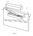
Figure 3 shows a schematic and simplified perspective view of a second embodiment of a door arrangement according to the present invention, wherein the door blade is in the closed position. -
Figure 4 shows an enlarged view of a portion ofFigure 3 . -
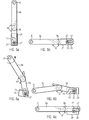
Figure 5a shows a schematic perspective view of a lever arm and slider element of the door arrangement ofFigures 3 and4 when the door blade is in the open position, the actuator is in a first actuator position and the lever arm is in a first lever arm position. -
Figure 5b shows a schematic perspective view of the lever arm and slider element of the door arrangement ofFigures 3 and4 when the door blade is in the closed position, the actuator is in a second actuator position and the lever arm is in a second lever arm position. -
Figure 6a shows a schematic perspective view of the lever arm and slider element of the door arrangement ofFigures 3 and4 while moving from the position shown inFigure 5a towards the position shown inFigure 5b . -
Figure 6b shows a schematic perspective view of the lever arm and slider element of the door arrangement ofFigures 3 and4 after the door blade has reached its closed position, wherein the actuator is in a third actuator position and the lever arm is in a third lever arm position. -
Figure 6c shows a schematic perspective view of the lever arm and slider element of the door arrangement ofFigures 3 and4 corresponding to the situation ofFigure 5b , wherein as compared toFigure 6b the actuator has been moved from the third actuator position into the second actuator position and the lever arm thereby has been moved from the third lever arm position into the second lever arm position while the door blade was still in the closed position, and wherein the door blade was subsequently moved slightly out of its closed position towards the open position. -
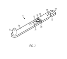
Figure 7 shows a schematic perspective view of the lever arm. - The door arrangement 1 shown in
Figures 1 and 2 is mounted inside an aircraft and comprises adoor blade 2 which is pivotably mounted to a wall portion 3 by means of ahinge 4. The wall portion 3 may, e.g., be part of a lavatory and of a galley of the aircraft. The wall portion 3 separates twoaircraft compartments compartment 15 may be, e.g., a cockpit or flight deck and thecompartment 16 may be, e.g., a passenger compartment. The wall portion 3 defines adoor opening 5 which can be selectively opened and closed by thedoor blade 2 by moving thedoor blade 2 into the open position shown inFigure 1 and the closed position shown inFigure 2 , respectively. When moving between the open and closed positions thedoor blade 2 pivots about a pivot axis defined by thehinge 4. - For the purpose of automatically moving the door blade between the open and closed positions under control of a control unit the door arrangement 1 comprises a
rotary actuator 6, which is rotatable about an actuator rotation axis 7, which extends parallel to but spaced from thehinge axis 4. Therotary actuator 6 is driven by, e.g., electric, hydraulic or pneumatic means to rotate about the actuator rotation axis 7 between various actuator positions. Theactuator 6 also comprises a pin 8, which extends parallel to but spaced from the actuator rotation axis 7. - An
elongate lever arm 9 is permanently and pivotably secured at oneend region 10 thereof to thedoor blade 2. At theopposite end region 11 thelever arm 9 is provided with an elongate throughhole 12, which has a generally oval shape and, with respect to the direction of extension of the pin 8 and the actuator rotation axis 7 is laterally defined by sidewalls orlateral walls 14. In the lateral walls 14 alateral opening 13 is provided allowing the pin 8 to enter and exit the throughhole 12 when theactuator 6 and the pin 8 are in specific positions, as will be explained in more detail below. - In the open position of the
door blade 2 shown inFigure 1 the pin 8 extends into or through the throughhole 12, such that theactuator 6 is mechanically coupled to thelever arm 9 via the pin 8 and to thedoor blade 2 via thelever arm 9. Theactuator 6 is in a first actuator position, in which the pin 8 is positioned such that it is prevented from exiting the throughhole 12 through thelateral opening 13. Thus, theactuator 6 maintains thedoor blade 2 in the open position, and upon operating theactuator 6 to rotate in the counterclockwise direction from the first actuator position towards the second actuator position shown inFigure 2 , theactuator 6 moves thedoor blade 2 via thelever arm 9 towards the closed position. - In this process the
lever arm 9 moves from the first lever arm position shown inFigure 1 and corresponding to the first actuator position towards the second lever arm position shown inFigure 2 . The second lever arm position is defined by a stop mechanism and is reached when thedoor blade 2 reaches the closed position. In this moment theactuator 6 is not yet in the second actuator position shown inFigure 2 , but in an intermediate third actuator position between the first and second actuator positions. In this third actuator position the pin 8 is still in engagement with the throughhole 12 to couple theactuator 6 to thelever arm 9. However, thelateral opening 13 is positioned such that upon operating theactuator 6 to rotate it further into the second actuator position the pin 8 escapes the throughhole 12 through thelateral opening 13 while thelever arm 9 maintains the defined second lever arm position, thereby mechanically decoupling theactuator 6 from thelever arm 9 and thedoor blade 2. The lever arm is spring loaded to maintain it in this position. Consequently, thedoor blade 2 is then able to move towards the open position independent of theactuator 6, in particular in case of a rapid decompression in thecompartment 15, without being impeded by theactuator 6, so that structural damage to the aircraft is prevented. - When operating the
actuator 6 to rotate from the second actuator position ofFigure 2 in the clockwise direction, the pin 8 enters the throughhole 12 through thelateral opening 13 immediately prior to theactuator 6 reaching the third actuator position, thereby reengaging the pin 8 and the throughhole 12 and coupling again theactuator 6 to thelever arm 9 and thedoor blade 2. - Thus, a very simple mechanism is provided which ensures that the
door blade 2 is reliably decoupled from theactuator 6 when thedoor blade 2 is in the closed position. -
Figures 3 to 7 show a further embodiment of a door arrangement 1, wherein the same reference numerals are used to designate like components. Different from the embodiment ofFigures 1 and 2 therotary actuator 6, which comprises anintegrated control unit 20, is fixedly and rigidly coupled to thelever arm 9 atend region 11 thereof. Along theupper edge 23 of the door blade 2 a slidingtrack 21 is mounted, wherein adistance block 22 is arranged between the slidingtrack 21 and thedoor blade 2 such that the slidingtrack 21 extends parallel to but spaced from theupper edge 23 of thedoor blade 2. - As shown in the enlarged view of
Figure 4 , aslider element 24 is supported in the slidingtrack 21 such that it is slidably movable in a guided manner along the slidingtrack 21. The movement of theslider element 24 within the slidingtrack 21 is limited by two end stops 25 and 26. Ascrew 27 extends from the upper surface of theslider element 24. At theend region 10 theelongate lever arm 9 is again provided with an elongate throughhole 12, which has a generally oval shape and, with respect to the direction of extension of thescrew 27 and the actuator rotation axis 7 is laterally defined by sidewalls or lateral walls 14 (see alsoFigure 7 ). In the lateral walls 14 alateral opening 13 is provided at one of the longitudinal ends of the elongate throughhole 12 allowing thescrew 27 to enter and exit the throughhole 12 when theactuator 6 and thescrew 27 are in specific positions, as will be explained in more detail below. - A more detailed view of the
lever arm 9 is shown inFigure 7 . As can be seen in that Figure, thelever arm 9 comprises twoelongate portions bolt 30. The coupling is such that the twoportions lever arm 9 is able to assume the straight configuration shown inFigure 7 and an angled configuration (seeFigures 6a and 6b ). Acoil spring 34 is provided for biasing thelever arm 9 into the straight configuration corresponding to an angle α of 180°, wherein anend stop bolt 31 is provided on theportion 9a, which cooperates with acurved end face 32 on theother portion 9b to stop the pivoting movement of theportions coil spring 34 in the straight configuration. Thecurved end face 32 is further configured in such a manner that the pivoting movement of theportions coil spring 34 is limited to an angle α, which is larger than 90° and preferably 120° or about 120°. This ensures that the mechanism does not jam. Further, the angle α is preferably significantly smaller than 180°, e.g. smaller than 160° and more preferably smaller than 150° and even more preferably smaller than 140°, in order to facilitate arranging the pin 8 at an end of the throughhole 12 remote from thelateral opening 13. - As shown in
Figure 5a , in the open position of thedoor blade 2 thelever arm 9 is in the straight configuration, and thescrew 27 is located inside the throughhole 12 out of alignment with thelateral opening 13. In fact, thescrew 27 is located at the opposite end of the throughhole 12 as compared to thelateral opening 13. This position of thelever arm 9 is a first lever arm position, which corresponds to a first actuator position. Further, theslider block 24 abuts theend stop 25, which assists in preventing movement of theslider 24 and, thereby, an inadvertent escape of thescrew 27 out of thelateral opening 13 during e.g. vibrations, flight maneuvers or turbulences. - In order to move the
door blade 2 into the closed position theactuator 6 is operated to rotate thelever arm 9 into the counterclockwise direction fromFigure 5a . Due to the out of alignment arrangement of thescrew 27 with respect to thelateral opening 13, thelever arm 9 is coupled to theslider block 24 and, thus, to thedoor blade 2 and is effective to pull thedoor blade 2 towards the closed position. However, as shown inFigure 6a , thelever arm 9 assumes the angled position with an angle defined by thestop bolt 31 and thecurved end face 32, as explained above. Further, due to the actuator rotation axis 7 and the pivot axis of the door blade being spaced, theslider element 24 moves away from theend stop 25 and along the slidingtrack 21 towards theend stop 26. - In a third actuator position the
door blade 2 eventually reaches the closed position, and theslider element 24 abuts theend stop 25 with thelever arm 9 still being in the angled configuration. This is illustrated inFigure 6b , from which it can be taken that thescrew 27 is still out of alignment with thelateral opening 13 and which shows thelever arm 9 in a third lever arm position. - As a final step of the closing process the
actuator 6 is then moved from the third actuator position in the opposite direction into a second actuator position between the first and third actuator positions. This actuator movement returns thelever arm 9 into the straight configuration. Due to the abutment with theend stop 25 theslider element 24 does not move further in the slidingtrack 21, so that thescrew 27 is maintained in a fixed position with respect to the slidingtrack 21 and thedoor blade 2 and thedoor blade 2 is maintained in the closed position. However, the straightening of thelever arm 9 increases the distance between the location, at which theactuator 6 is secured to thelever arm 9, and thelateral opening 13 and, generally, the distance between the twoend regions lever arm 9. Consequently, the throughhole 12 moves with respect to thescrew 27, so that thescrew 27 moves inside the throughhole 12 towards the longitudinal end of the throughhole 12 at which thelateral opening 13 is provided. The throughhole 12 is dimensioned and thelateral opening 13 is arranged such that thescrew 27 is in alignment with thelateral opening 13 as soon as theactuator 6 has reached the second actuator position (coming from the third actuator position) and thelever arm 9 has assumed the straight configuration, which is a second lever arm position (seeFigures 5b and 6c ). - The lever arm position of
Figure 6c is the same as the one shown inFigure 5b . In that position, which is reached while thedoor blade 2 is in the closed position, thescrew 27 is still engaged in the throughhole 12, but - as indicated inFigure 6c - thedoor blade 2 is nevertheless able to move towards the open position independent of theactuator 6, in particular in case of a rapid decompression in thecompartment 15, without being impeded by theactuator 6, so that structural damage to the aircraft is prevented. This is because thescrew 27 is positioned to be able to leave the throughhole 12 through thelateral opening 13. - For moving the
door blade 2 into the open position it is sufficient to operate theactuator 6 to move thelever arm 9 from the position ofFigure 5b (and Figure 6c ) into the position ofFigure 5a . During this movement thelever arm 9 maintains its straight configuration, and, due to the actuator rotation axis 7 and the pivot axis of the door blade being spaced from each other, theslider element 24 moves along the slidingtrack 21 towards theend stop 25. Theend stop 25 is positioned such that theslider element 24 abuts theend stop 25 prior to thedoor blade 2 reaching the open position and thelever arm 9 reaching the position ofFigure 5a . Consequently, further rotation of theactuator 6 into the first actuator position causes thescrew 27 to move inside the throughhole 12 out of alignment with thelateral opening 13. - Thus, a very simple mechanism is again provided which ensures that the
door blade 2 is reliably decoupled from theactuator 6 with respect to an opening movement of thedoor blade 2 when thedoor blade 2 is in the closed position.
Claims (15)
- A door arrangement for the interior of an aircraft, the door arrangement comprising- a frame portion,- a door blade (2) hinged to the frame portion to be pivotable about a pivot axis (4) between a closed position, in which the door blade (2) closes a door opening (5) defined by the frame portion, and an open position, in which the door blade (2) is positioned to allow access through the door opening (5),- a lever arm (9), and- an actuator (6) mounted to the frame portion and operable to selectively move the door blade (2) between the open position and the closed position via the lever arm (9) engaging the door blade (2) and the actuator (6), wherein the actuator (6) is movable into a first actuator position, in which the lever arm (9) is in a first lever arm position and the door blade (2) is in the open position, and into a second actuator position, in which the lever arm (9) is in a second lever arm position and the door blade (2) is in the closed position,characterized in that the actuator (6) is movable into the second actuator position such that the door blade (2) is able to move from the closed position towards the open position independent of the actuator (6) while the actuator (6) remains in the second actuator position.
- The door arrangement according to claim 1, wherein the actuator (6) is movable into a third actuator position, in which the door blade (2) is in the closed position and which the actuator (6) assumes upon reaching the closed position when the actuator (6) is operated to move the door blade (2) from the open position into the closed position,
wherein in the third actuator position the lever arm (9) is in engagement with the door blade (2) and with the actuator (6) such that the door blade (2) is prevented from moving from the closed position towards the open position independent of the actuator (6), and
wherein movement of the actuator (6) from the third actuator position into the second actuator position changes the engagement between the lever arm (9) and the door blade (2) or actuator (6) such that the movement of the door blade (2) from the closed position towards the open position independent of the actuator (6) is enabled. - The door arrangement according to claim 1 or claim 2, further comprising an engagement element (8, 27) coupled to the actuator (6) or to the door blade (2),
wherein the lever arm (9) comprises an elongate slot (12) adapted to engage the engagement element (8, 27) to allow the actuator (6) to effect the movement of the door blade (2) between the open position and the closed position via the lever arm (9), and
wherein the elongate slot (12) comprises a lateral opening (13) which, by moving the actuator (6) from the first actuator position to the second actuator position, is positionable such that the engagement element (8, 27) is allowed to escape the slot (12) through the lateral opening (13), thereby allowing the movement of the door blade (2) from the closed position towards the open position independent of the actuator (6). - The door arrangement according to claims 2 and 3, wherein when operating the actuator (6) to move from the first actuator position into the third actuator position and to move from the third actuator position into the second actuator position the actuator (6) is moved in the same direction,
wherein movement of the actuator (6) from the third actuator position into the second actuator position causes the engagement element (8) to escape the slot (12) through the lateral opening (13) and thereby disengagement of the engagement element (8) from the lever arm (9) to allow the movement of the door blade (2) from the closed position towards the open position independent of the actuator (6), and
wherein movement of the actuator (6) from the second actuator position into the third actuator position while the door blade (2) is in the closed position causes the engagement element (8) to enter the slot (12) through the lateral opening (13) and thereby engagement of the engagement element (8) with the lever arm (9) to prevent the door blade (2) from moving from the closed position towards the open position independent of the actuator (6). - The door arrangement according to claim 4, wherein the engagement element (8) is coupled to the actuator (6), and the lever arm (9) is pivotably secured to the door blade (2).
- The door arrangement according to claim 4 or claim 5, further comprising a lever arm stop mechanism, which is arranged such that when the actuator (6) is operated to move the actuator (6) from the first actuator position towards the second actuator position the movement of the lever arm (9) is stopped by the lever arm stop mechanism upon the actuator (6) reaching the third position and the lever arm stop mechanism thereby defines the second lever arm position.
- The door arrangement according to claims 2 and 3, wherein when operating the actuator (6) to move from the first actuator position into the third actuator position and to move from the third actuator position into the second actuator position the actuator (6) is moved in opposite directions,
wherein movement of the actuator (6) from the third actuator position into the second actuator position causes the engagement element (27) to be positioned within the slot (12) in alignment with the lateral opening (13) when the actuator (6) is in the second actuator position, thereby allowing the movement of the door blade (2) from the closed position towards the open position independent of the actuator (6) by the engagement element (27) escaping the slot (12) through the lateral opening (13), and wherein movement of the actuator (6) from the second actuator position into the first actuator position causes the engagement element (27) to be positioned within the slot (12) out of alignment with the lateral opening (13) when the actuator (6) is in the first actuator position, thereby preventing the engagement element (27) from escaping the slot (12) through the lateral opening (13) when operating the actuator (6) for moving the door blade (2) from the open position into the closed position. - The door arrangement according to claim 7, wherein the engagement element (27) is coupled to the door blade (2), and the lever arm (9) is secured to the actuator (6).
- The door arrangement according to claim 7 or claim 8, further comprising a sliding track (21) provided on the door blade (2), wherein the engagement element (27) is secured to or part of a slider element (24) slidably secured in the sliding track (21).
- The door arrangement according to claim 9, further comprising a first end stop (25) and a second end stop (26) limiting movement of the slider element (24) along the sliding track (21), wherein the slider element (24) is movable along the sliding track (21) between the first and second end stops (25, 26), and wherein the slider element (24) abuts the first end stop (25) when the actuator (6) is in the first actuator position and the slider element (24) abuts the second end stop (26) when the actuator (6) is in the second actuator position.
- The door arrangement according to claim 10, wherein the second end stop (26) is positioned such that, when the actuator (6) is operated to move the door blade (2) from the open position into the closed position by moving the actuator (6) at first from the first actuator position into the third actuator position and subsequently from the third actuator position into the second actuator position,- in the third actuator position the slider element (24) abuts the second end stop (26), the lever arm (9) is in a third lever arm position different from the second lever arm position, and the engagement element (27) is positioned within the slot (12) out of alignment with the lateral opening (13), and- when subsequently moving the actuator (6) from the third actuator position into the second actuator position the abutment between the slider element (24) and the second end stop (26) is maintained and movement of the lever arm (9) from the third lever arm position into the second lever arm position thereby causes movement of the engagement element (27) along the slot (12) into a position in alignment with the lateral opening (13).
- The door arrangement according to claim 11, wherein the lever arm (9) comprises two portions (9a, 9b), which are connected to each other to be pivotable with respect to each other about a pivot axis (30), and stop means (31, 32, 34) adapted to limit the pivoting movement of the two portions with respect to each other between a first angle and a second angle, wherein
the slot (12) is provided in one (9b) of the two portions (9a, 9b) and the actuator (6) is secured to the other one (9a) of the two portions (9a, 9b),
the distance between a location at which the lever arm (9) contacts the actuator (6) and the slot (12) is greater when the two portions (9a, 9b) assume the first angle than when the two portions (9a, 9b) assume the second angle,
in the third lever arm position the two portions (9a, 9b) assume the second angle and in the second lever arm position the two portions (9a, 9b) assume the first angle, and the increase of the distance between the location at which the lever arm (9) contacts the actuator (6) and the slot (12) upon movement of the actuator (6) from the third actuator position into the second actuator position together with the abutment of the slider element (24) against the second end stop (26) causes the movement of the engagement element (27) along the slot (12) from a position out of alignment with the lateral opening (13) into a position in alignment with the lateral opening (13). - The door arrangement according to any of claims 10 to claim 12, wherein the first end stop (25) is positioned such that, when the actuator (6) is operated to move the door blade (2) from the closed position into the open position by moving the actuator (6) from the second actuator position into the first actuator position,- the slider element (24) moves along the sliding track (21) from the second end stop (26) towards the first end stop (25) while the engagement element (27) is positioned within the slot (12) in alignment with the lateral opening (13),- the slider element (24) reaches and abuts the first end stop (25) prior to the actuator (6) reaching the first actuator position, and- during further movement of the actuator (6) into the first actuator position the abutment between the slider element (24) and the first end stop (25) is maintained and movement of the lever arm (9) into the first lever arm position thereby causes movement of the engagement element (27) along the slot (12) into a position out of alignment with the lateral opening (13) .
- The door arrangement according to any of the preceding claims, wherein the actuator (6) is a rotary actuator having an axis (7) of rotation spaced from the pivot axis (4) of the door blade (2).
- An aircraft comprising a first compartment (15) and a second compartment (16) separated by a wall (3), wherein an aircraft door arrangement (1) according to any of the preceding claims is provided in the wall (3).
Priority Applications (2)
| Application Number | Priority Date | Filing Date | Title |
|---|---|---|---|
| EP15166655.9A EP3090938B1 (en) | 2015-05-06 | 2015-05-06 | Door arrangement for the interior of an aircraft and aircraft comprising such a door arrangement |
| US15/147,470 US10124878B2 (en) | 2015-05-06 | 2016-05-05 | Door arrangement for the interior of an aircraft and aircraft comprising such a door arrangement |
Applications Claiming Priority (1)
| Application Number | Priority Date | Filing Date | Title |
|---|---|---|---|
| EP15166655.9A EP3090938B1 (en) | 2015-05-06 | 2015-05-06 | Door arrangement for the interior of an aircraft and aircraft comprising such a door arrangement |
Publications (2)
| Publication Number | Publication Date |
|---|---|
| EP3090938A1 true EP3090938A1 (en) | 2016-11-09 |
| EP3090938B1 EP3090938B1 (en) | 2018-04-11 |
Family
ID=53054918
Family Applications (1)
| Application Number | Title | Priority Date | Filing Date |
|---|---|---|---|
| EP15166655.9A Not-in-force EP3090938B1 (en) | 2015-05-06 | 2015-05-06 | Door arrangement for the interior of an aircraft and aircraft comprising such a door arrangement |
Country Status (2)
| Country | Link |
|---|---|
| US (1) | US10124878B2 (en) |
| EP (1) | EP3090938B1 (en) |
Families Citing this family (6)
| Publication number | Priority date | Publication date | Assignee | Title |
|---|---|---|---|---|
| WO2015035359A1 (en) * | 2013-09-09 | 2015-03-12 | Yale Security, Inc. | Apparatus for connecting door closer or operator to swing door |
| AU2018258954B2 (en) * | 2017-04-24 | 2024-06-13 | Assa Abloy Entrance Systems Ab | Swing door operator |
| DE102020128865B4 (en) * | 2020-11-03 | 2024-02-08 | Dr. Ing. H.C. F. Porsche Aktiengesellschaft | Front flap drive, front flap system and motor vehicle |
| WO2023100552A1 (en) * | 2021-12-02 | 2023-06-08 | 横浜ゴム株式会社 | Door opening and closing mechanism of aircraft lavatory unit |
| JP7230999B1 (en) * | 2021-12-02 | 2023-03-01 | 横浜ゴム株式会社 | Airplane lavatory unit door opening/closing mechanism |
| DE102022116438A1 (en) * | 2022-07-01 | 2024-01-04 | Bayerische Motoren Werke Aktiengesellschaft | Front lid hinge for a motor vehicle and motor vehicle with such a front lid hinge |
Citations (5)
| Publication number | Priority date | Publication date | Assignee | Title |
|---|---|---|---|---|
| WO1984001404A1 (en) * | 1982-09-30 | 1984-04-12 | Boeing Co | Door anti-hijacking latch/lock mechanism with pneumatic decompression override |
| GB2144484A (en) * | 1983-08-04 | 1985-03-06 | British Aerospace | Door locking mechanism |
| US5255946A (en) * | 1991-01-26 | 1993-10-26 | Deutsche Aerospace Airbus Gmbh | Apparatus for locking and unlocking a flap door |
| US20020092951A1 (en) * | 2001-01-16 | 2002-07-18 | Asher Haviv | Lock system for aircraft cockpit door |
| WO2014027215A1 (en) * | 2012-08-17 | 2014-02-20 | Bombardier Inc. | Door assembly for aircraft interior |
Family Cites Families (6)
| Publication number | Priority date | Publication date | Assignee | Title |
|---|---|---|---|---|
| CH531120A (en) * | 1971-11-29 | 1972-11-30 | Magnetic Elektromotoren Ag | Drive device for opening and closing doors |
| KR0164762B1 (en) * | 1995-11-09 | 1999-04-15 | 김광호 | Control method of automatic door switch of a washing machine |
| US5752344A (en) * | 1997-02-28 | 1998-05-19 | Doorking Inc. | Swing gate operator |
| JP3982391B2 (en) * | 2002-11-14 | 2007-09-26 | アイシン精機株式会社 | Drive device |
| US20040118976A1 (en) * | 2002-12-10 | 2004-06-24 | Joseph Albertelli | Secure composite cockpit door and method of manufacture |
| DE102011009481A1 (en) * | 2011-01-26 | 2012-07-26 | Airbus Operations Gmbh | Door arrangement with two door leaves |
-
2015
- 2015-05-06 EP EP15166655.9A patent/EP3090938B1/en not_active Not-in-force
-
2016
- 2016-05-05 US US15/147,470 patent/US10124878B2/en active Active
Patent Citations (5)
| Publication number | Priority date | Publication date | Assignee | Title |
|---|---|---|---|---|
| WO1984001404A1 (en) * | 1982-09-30 | 1984-04-12 | Boeing Co | Door anti-hijacking latch/lock mechanism with pneumatic decompression override |
| GB2144484A (en) * | 1983-08-04 | 1985-03-06 | British Aerospace | Door locking mechanism |
| US5255946A (en) * | 1991-01-26 | 1993-10-26 | Deutsche Aerospace Airbus Gmbh | Apparatus for locking and unlocking a flap door |
| US20020092951A1 (en) * | 2001-01-16 | 2002-07-18 | Asher Haviv | Lock system for aircraft cockpit door |
| WO2014027215A1 (en) * | 2012-08-17 | 2014-02-20 | Bombardier Inc. | Door assembly for aircraft interior |
Also Published As
| Publication number | Publication date |
|---|---|
| US10124878B2 (en) | 2018-11-13 |
| US20160325817A1 (en) | 2016-11-10 |
| EP3090938B1 (en) | 2018-04-11 |
Similar Documents
| Publication | Publication Date | Title |
|---|---|---|
| EP3090938B1 (en) | Door arrangement for the interior of an aircraft and aircraft comprising such a door arrangement | |
| JP6804529B2 (en) | Aircraft emergency exit doors with integrated mechanism and how to open / close the doors | |
| JP3947511B2 (en) | Aircraft cockpit door | |
| EP3323709A1 (en) | An actuatable emergency exit door and an aircraft or space craft with a pressurized cabin having such an actuatable emergency exit door | |
| US6651387B2 (en) | Locking controller of a sliding door | |
| JP2013500411A (en) | Drive unit for movable furniture | |
| CN105857566B (en) | Aircraft cockpit equipped with a safety vent | |
| CA2936613C (en) | Device for opening an aircraft door | |
| US9932758B2 (en) | Watertight door or window | |
| US10919611B2 (en) | Opening and secure-closing system | |
| US20080295550A1 (en) | Door Lock, Especially Comprising a Panic Function | |
| US11591063B2 (en) | Separating element for a platform cabin, platform comprising such an element and method for using such an element | |
| CN101218150B (en) | Emergency opening device for overhead storage compartments with lowerable housing | |
| US12049295B2 (en) | Emergency opening device for an aircraft door, with handle release | |
| US11820484B2 (en) | Aircraft door having a mechanism for conditional opening along two trajectories | |
| KR100828820B1 (en) | Hold open lock structure of sliding door | |
| US5255946A (en) | Apparatus for locking and unlocking a flap door | |
| US7959108B2 (en) | Control device for locking and unlocking and aircraft door and aircraft door that integrates such a device | |
| IE86213B1 (en) | Friction stay | |
| US20250108903A1 (en) | Aircraft door mechanism | |
| JP2018104887A (en) | Automatic closing device for fire door | |
| US9260902B2 (en) | Sliding roof window | |
| EP2022913A2 (en) | An incorrect operation safety lock device for window units | |
| BR112021008754B1 (en) | EMERGENCY OPENING DEVICE FOR AIRCRAFT DOOR, WITH HANDLE RELEASE |
Legal Events
| Date | Code | Title | Description |
|---|---|---|---|
| PUAI | Public reference made under article 153(3) epc to a published international application that has entered the european phase |
Free format text: ORIGINAL CODE: 0009012 |
|
| AK | Designated contracting states |
Kind code of ref document: A1 Designated state(s): AL AT BE BG CH CY CZ DE DK EE ES FI FR GB GR HR HU IE IS IT LI LT LU LV MC MK MT NL NO PL PT RO RS SE SI SK SM TR |
|
| AX | Request for extension of the european patent |
Extension state: BA ME |
|
| 17P | Request for examination filed |
Effective date: 20170509 |
|
| RBV | Designated contracting states (corrected) |
Designated state(s): AL AT BE BG CH CY CZ DE DK EE ES FI FR GB GR HR HU IE IS IT LI LT LU LV MC MK MT NL NO PL PT RO RS SE SI SK SM TR |
|
| GRAP | Despatch of communication of intention to grant a patent |
Free format text: ORIGINAL CODE: EPIDOSNIGR1 |
|
| INTG | Intention to grant announced |
Effective date: 20171020 |
|
| GRAS | Grant fee paid |
Free format text: ORIGINAL CODE: EPIDOSNIGR3 |
|
| GRAA | (expected) grant |
Free format text: ORIGINAL CODE: 0009210 |
|
| AK | Designated contracting states |
Kind code of ref document: B1 Designated state(s): AL AT BE BG CH CY CZ DE DK EE ES FI FR GB GR HR HU IE IS IT LI LT LU LV MC MK MT NL NO PL PT RO RS SE SI SK SM TR |
|
| REG | Reference to a national code |
Ref country code: GB Ref legal event code: FG4D |
|
| REG | Reference to a national code |
Ref country code: CH Ref legal event code: EP |
|
| REG | Reference to a national code |
Ref country code: AT Ref legal event code: REF Ref document number: 987744 Country of ref document: AT Kind code of ref document: T Effective date: 20180415 |
|
| REG | Reference to a national code |
Ref country code: IE Ref legal event code: FG4D |
|
| REG | Reference to a national code |
Ref country code: DE Ref legal event code: R096 Ref document number: 602015009738 Country of ref document: DE |
|
| REG | Reference to a national code |
Ref country code: FR Ref legal event code: PLFP Year of fee payment: 4 |
|
| REG | Reference to a national code |
Ref country code: NL Ref legal event code: MP Effective date: 20180411 |
|
| REG | Reference to a national code |
Ref country code: LT Ref legal event code: MG4D |
|
| PG25 | Lapsed in a contracting state [announced via postgrant information from national office to epo] |
Ref country code: NL Free format text: LAPSE BECAUSE OF FAILURE TO SUBMIT A TRANSLATION OF THE DESCRIPTION OR TO PAY THE FEE WITHIN THE PRESCRIBED TIME-LIMIT Effective date: 20180411 |
|
| PG25 | Lapsed in a contracting state [announced via postgrant information from national office to epo] |
Ref country code: SE Free format text: LAPSE BECAUSE OF FAILURE TO SUBMIT A TRANSLATION OF THE DESCRIPTION OR TO PAY THE FEE WITHIN THE PRESCRIBED TIME-LIMIT Effective date: 20180411 Ref country code: ES Free format text: LAPSE BECAUSE OF FAILURE TO SUBMIT A TRANSLATION OF THE DESCRIPTION OR TO PAY THE FEE WITHIN THE PRESCRIBED TIME-LIMIT Effective date: 20180411 Ref country code: AL Free format text: LAPSE BECAUSE OF FAILURE TO SUBMIT A TRANSLATION OF THE DESCRIPTION OR TO PAY THE FEE WITHIN THE PRESCRIBED TIME-LIMIT Effective date: 20180411 Ref country code: PL Free format text: LAPSE BECAUSE OF FAILURE TO SUBMIT A TRANSLATION OF THE DESCRIPTION OR TO PAY THE FEE WITHIN THE PRESCRIBED TIME-LIMIT Effective date: 20180411 Ref country code: NO Free format text: LAPSE BECAUSE OF FAILURE TO SUBMIT A TRANSLATION OF THE DESCRIPTION OR TO PAY THE FEE WITHIN THE PRESCRIBED TIME-LIMIT Effective date: 20180711 Ref country code: FI Free format text: LAPSE BECAUSE OF FAILURE TO SUBMIT A TRANSLATION OF THE DESCRIPTION OR TO PAY THE FEE WITHIN THE PRESCRIBED TIME-LIMIT Effective date: 20180411 Ref country code: BG Free format text: LAPSE BECAUSE OF FAILURE TO SUBMIT A TRANSLATION OF THE DESCRIPTION OR TO PAY THE FEE WITHIN THE PRESCRIBED TIME-LIMIT Effective date: 20180711 Ref country code: LT Free format text: LAPSE BECAUSE OF FAILURE TO SUBMIT A TRANSLATION OF THE DESCRIPTION OR TO PAY THE FEE WITHIN THE PRESCRIBED TIME-LIMIT Effective date: 20180411 |
|
| PG25 | Lapsed in a contracting state [announced via postgrant information from national office to epo] |
Ref country code: HR Free format text: LAPSE BECAUSE OF FAILURE TO SUBMIT A TRANSLATION OF THE DESCRIPTION OR TO PAY THE FEE WITHIN THE PRESCRIBED TIME-LIMIT Effective date: 20180411 Ref country code: RS Free format text: LAPSE BECAUSE OF FAILURE TO SUBMIT A TRANSLATION OF THE DESCRIPTION OR TO PAY THE FEE WITHIN THE PRESCRIBED TIME-LIMIT Effective date: 20180411 Ref country code: GR Free format text: LAPSE BECAUSE OF FAILURE TO SUBMIT A TRANSLATION OF THE DESCRIPTION OR TO PAY THE FEE WITHIN THE PRESCRIBED TIME-LIMIT Effective date: 20180712 Ref country code: LV Free format text: LAPSE BECAUSE OF FAILURE TO SUBMIT A TRANSLATION OF THE DESCRIPTION OR TO PAY THE FEE WITHIN THE PRESCRIBED TIME-LIMIT Effective date: 20180411 |
|
| REG | Reference to a national code |
Ref country code: CH Ref legal event code: PL |
|
| REG | Reference to a national code |
Ref country code: AT Ref legal event code: MK05 Ref document number: 987744 Country of ref document: AT Kind code of ref document: T Effective date: 20180411 |
|
| PG25 | Lapsed in a contracting state [announced via postgrant information from national office to epo] |
Ref country code: PT Free format text: LAPSE BECAUSE OF FAILURE TO SUBMIT A TRANSLATION OF THE DESCRIPTION OR TO PAY THE FEE WITHIN THE PRESCRIBED TIME-LIMIT Effective date: 20180813 |
|
| REG | Reference to a national code |
Ref country code: DE Ref legal event code: R097 Ref document number: 602015009738 Country of ref document: DE |
|
| REG | Reference to a national code |
Ref country code: BE Ref legal event code: MM Effective date: 20180531 |
|
| PG25 | Lapsed in a contracting state [announced via postgrant information from national office to epo] |
Ref country code: MC Free format text: LAPSE BECAUSE OF FAILURE TO SUBMIT A TRANSLATION OF THE DESCRIPTION OR TO PAY THE FEE WITHIN THE PRESCRIBED TIME-LIMIT Effective date: 20180411 Ref country code: CZ Free format text: LAPSE BECAUSE OF FAILURE TO SUBMIT A TRANSLATION OF THE DESCRIPTION OR TO PAY THE FEE WITHIN THE PRESCRIBED TIME-LIMIT Effective date: 20180411 Ref country code: AT Free format text: LAPSE BECAUSE OF FAILURE TO SUBMIT A TRANSLATION OF THE DESCRIPTION OR TO PAY THE FEE WITHIN THE PRESCRIBED TIME-LIMIT Effective date: 20180411 Ref country code: DK Free format text: LAPSE BECAUSE OF FAILURE TO SUBMIT A TRANSLATION OF THE DESCRIPTION OR TO PAY THE FEE WITHIN THE PRESCRIBED TIME-LIMIT Effective date: 20180411 Ref country code: EE Free format text: LAPSE BECAUSE OF FAILURE TO SUBMIT A TRANSLATION OF THE DESCRIPTION OR TO PAY THE FEE WITHIN THE PRESCRIBED TIME-LIMIT Effective date: 20180411 Ref country code: SK Free format text: LAPSE BECAUSE OF FAILURE TO SUBMIT A TRANSLATION OF THE DESCRIPTION OR TO PAY THE FEE WITHIN THE PRESCRIBED TIME-LIMIT Effective date: 20180411 Ref country code: RO Free format text: LAPSE BECAUSE OF FAILURE TO SUBMIT A TRANSLATION OF THE DESCRIPTION OR TO PAY THE FEE WITHIN THE PRESCRIBED TIME-LIMIT Effective date: 20180411 |
|
| PLBE | No opposition filed within time limit |
Free format text: ORIGINAL CODE: 0009261 |
|
| STAA | Information on the status of an ep patent application or granted ep patent |
Free format text: STATUS: NO OPPOSITION FILED WITHIN TIME LIMIT |
|
| REG | Reference to a national code |
Ref country code: IE Ref legal event code: MM4A |
|
| PG25 | Lapsed in a contracting state [announced via postgrant information from national office to epo] |
Ref country code: LI Free format text: LAPSE BECAUSE OF NON-PAYMENT OF DUE FEES Effective date: 20180531 Ref country code: IT Free format text: LAPSE BECAUSE OF FAILURE TO SUBMIT A TRANSLATION OF THE DESCRIPTION OR TO PAY THE FEE WITHIN THE PRESCRIBED TIME-LIMIT Effective date: 20180411 Ref country code: CH Free format text: LAPSE BECAUSE OF NON-PAYMENT OF DUE FEES Effective date: 20180531 Ref country code: SM Free format text: LAPSE BECAUSE OF FAILURE TO SUBMIT A TRANSLATION OF THE DESCRIPTION OR TO PAY THE FEE WITHIN THE PRESCRIBED TIME-LIMIT Effective date: 20180411 |
|
| 26N | No opposition filed |
Effective date: 20190114 |
|
| PG25 | Lapsed in a contracting state [announced via postgrant information from national office to epo] |
Ref country code: LU Free format text: LAPSE BECAUSE OF NON-PAYMENT OF DUE FEES Effective date: 20180506 |
|
| PG25 | Lapsed in a contracting state [announced via postgrant information from national office to epo] |
Ref country code: IE Free format text: LAPSE BECAUSE OF NON-PAYMENT OF DUE FEES Effective date: 20180506 |
|
| PG25 | Lapsed in a contracting state [announced via postgrant information from national office to epo] |
Ref country code: BE Free format text: LAPSE BECAUSE OF NON-PAYMENT OF DUE FEES Effective date: 20180531 Ref country code: SI Free format text: LAPSE BECAUSE OF FAILURE TO SUBMIT A TRANSLATION OF THE DESCRIPTION OR TO PAY THE FEE WITHIN THE PRESCRIBED TIME-LIMIT Effective date: 20180411 |
|
| PG25 | Lapsed in a contracting state [announced via postgrant information from national office to epo] |
Ref country code: MT Free format text: LAPSE BECAUSE OF NON-PAYMENT OF DUE FEES Effective date: 20180506 |
|
| PG25 | Lapsed in a contracting state [announced via postgrant information from national office to epo] |
Ref country code: TR Free format text: LAPSE BECAUSE OF FAILURE TO SUBMIT A TRANSLATION OF THE DESCRIPTION OR TO PAY THE FEE WITHIN THE PRESCRIBED TIME-LIMIT Effective date: 20180411 |
|
| PG25 | Lapsed in a contracting state [announced via postgrant information from national office to epo] |
Ref country code: HU Free format text: LAPSE BECAUSE OF FAILURE TO SUBMIT A TRANSLATION OF THE DESCRIPTION OR TO PAY THE FEE WITHIN THE PRESCRIBED TIME-LIMIT; INVALID AB INITIO Effective date: 20150506 Ref country code: CY Free format text: LAPSE BECAUSE OF FAILURE TO SUBMIT A TRANSLATION OF THE DESCRIPTION OR TO PAY THE FEE WITHIN THE PRESCRIBED TIME-LIMIT Effective date: 20180411 Ref country code: MK Free format text: LAPSE BECAUSE OF NON-PAYMENT OF DUE FEES Effective date: 20180411 |
|
| PG25 | Lapsed in a contracting state [announced via postgrant information from national office to epo] |
Ref country code: IS Free format text: LAPSE BECAUSE OF FAILURE TO SUBMIT A TRANSLATION OF THE DESCRIPTION OR TO PAY THE FEE WITHIN THE PRESCRIBED TIME-LIMIT Effective date: 20180811 |
|
| PGFP | Annual fee paid to national office [announced via postgrant information from national office to epo] |
Ref country code: GB Payment date: 20220520 Year of fee payment: 8 Ref country code: FR Payment date: 20220524 Year of fee payment: 8 Ref country code: DE Payment date: 20220519 Year of fee payment: 8 |
|
| REG | Reference to a national code |
Ref country code: DE Ref legal event code: R119 Ref document number: 602015009738 Country of ref document: DE |
|
| GBPC | Gb: european patent ceased through non-payment of renewal fee |
Effective date: 20230506 |
|
| PG25 | Lapsed in a contracting state [announced via postgrant information from national office to epo] |
Ref country code: DE Free format text: LAPSE BECAUSE OF NON-PAYMENT OF DUE FEES Effective date: 20231201 Ref country code: GB Free format text: LAPSE BECAUSE OF NON-PAYMENT OF DUE FEES Effective date: 20230506 |
|
| PG25 | Lapsed in a contracting state [announced via postgrant information from national office to epo] |
Ref country code: FR Free format text: LAPSE BECAUSE OF NON-PAYMENT OF DUE FEES Effective date: 20230531 |