EP3090932A1 - Bicycle seat with resilient support - Google Patents
Bicycle seat with resilient support Download PDFInfo
- Publication number
- EP3090932A1 EP3090932A1 EP16166290.3A EP16166290A EP3090932A1 EP 3090932 A1 EP3090932 A1 EP 3090932A1 EP 16166290 A EP16166290 A EP 16166290A EP 3090932 A1 EP3090932 A1 EP 3090932A1
- Authority
- EP
- European Patent Office
- Prior art keywords
- engagement member
- bicycle seat
- seat support
- upper engagement
- support
- Prior art date
- Legal status (The legal status is an assumption and is not a legal conclusion. Google has not performed a legal analysis and makes no representation as to the accuracy of the status listed.)
- Withdrawn
Links
- 230000008878 coupling Effects 0.000 claims abstract description 3
- 238000010168 coupling process Methods 0.000 claims abstract description 3
- 238000005859 coupling reaction Methods 0.000 claims abstract description 3
- 229910045601 alloy Inorganic materials 0.000 description 5
- 239000000956 alloy Substances 0.000 description 5
- 239000000463 material Substances 0.000 description 5
- 229910000831 Steel Inorganic materials 0.000 description 4
- RTAQQCXQSZGOHL-UHFFFAOYSA-N Titanium Chemical compound [Ti] RTAQQCXQSZGOHL-UHFFFAOYSA-N 0.000 description 4
- 239000002131 composite material Substances 0.000 description 4
- 239000010959 steel Substances 0.000 description 4
- 239000010936 titanium Substances 0.000 description 4
- 229910052719 titanium Inorganic materials 0.000 description 4
- 229920000049 Carbon (fiber) Polymers 0.000 description 3
- 239000004593 Epoxy Substances 0.000 description 3
- 239000000853 adhesive Substances 0.000 description 3
- 230000001070 adhesive effect Effects 0.000 description 3
- 239000004917 carbon fiber Substances 0.000 description 3
- 239000011159 matrix material Substances 0.000 description 3
- 229910052751 metal Inorganic materials 0.000 description 3
- 239000002184 metal Substances 0.000 description 3
- 239000012858 resilient material Substances 0.000 description 3
- 230000035939 shock Effects 0.000 description 2
- 125000006850 spacer group Chemical group 0.000 description 2
- 230000003068 static effect Effects 0.000 description 2
- 238000010521 absorption reaction Methods 0.000 description 1
- 238000010276 construction Methods 0.000 description 1
- 230000001419 dependent effect Effects 0.000 description 1
- 229910001092 metal group alloy Inorganic materials 0.000 description 1
- 229920003225 polyurethane elastomer Polymers 0.000 description 1
Images


Classifications
-
- B—PERFORMING OPERATIONS; TRANSPORTING
- B62—LAND VEHICLES FOR TRAVELLING OTHERWISE THAN ON RAILS
- B62J—CYCLE SADDLES OR SEATS; AUXILIARY DEVICES OR ACCESSORIES SPECIALLY ADAPTED TO CYCLES AND NOT OTHERWISE PROVIDED FOR, e.g. ARTICLE CARRIERS OR CYCLE PROTECTORS
- B62J1/00—Saddles or other seats for cycles; Arrangement thereof; Component parts
- B62J1/02—Saddles resiliently mounted on the frame; Equipment therefor, e.g. springs
-
- B—PERFORMING OPERATIONS; TRANSPORTING
- B62—LAND VEHICLES FOR TRAVELLING OTHERWISE THAN ON RAILS
- B62J—CYCLE SADDLES OR SEATS; AUXILIARY DEVICES OR ACCESSORIES SPECIALLY ADAPTED TO CYCLES AND NOT OTHERWISE PROVIDED FOR, e.g. ARTICLE CARRIERS OR CYCLE PROTECTORS
- B62J1/00—Saddles or other seats for cycles; Arrangement thereof; Component parts
-
- A—HUMAN NECESSITIES
- A47—FURNITURE; DOMESTIC ARTICLES OR APPLIANCES; COFFEE MILLS; SPICE MILLS; SUCTION CLEANERS IN GENERAL
- A47C—CHAIRS; SOFAS; BEDS
- A47C7/00—Parts, details, or accessories of chairs or stools
- A47C7/002—Chair or stool bases
- A47C7/004—Chair or stool bases for chairs or stools with central column, e.g. office chairs
-
- A—HUMAN NECESSITIES
- A47—FURNITURE; DOMESTIC ARTICLES OR APPLIANCES; COFFEE MILLS; SPICE MILLS; SUCTION CLEANERS IN GENERAL
- A47C—CHAIRS; SOFAS; BEDS
- A47C7/00—Parts, details, or accessories of chairs or stools
- A47C7/56—Parts or details of tipping-up chairs, e.g. of theatre chairs
- A47C7/58—Hinges, e.g. for mounting chairs in a curved row
-
- B—PERFORMING OPERATIONS; TRANSPORTING
- B62—LAND VEHICLES FOR TRAVELLING OTHERWISE THAN ON RAILS
- B62J—CYCLE SADDLES OR SEATS; AUXILIARY DEVICES OR ACCESSORIES SPECIALLY ADAPTED TO CYCLES AND NOT OTHERWISE PROVIDED FOR, e.g. ARTICLE CARRIERS OR CYCLE PROTECTORS
- B62J1/00—Saddles or other seats for cycles; Arrangement thereof; Component parts
- B62J1/02—Saddles resiliently mounted on the frame; Equipment therefor, e.g. springs
- B62J1/04—Saddles capable of swinging about a horizontal pivot
Definitions
- the present invention relates to bicycle seats, and particularly to resilient seat supports.
- Bicycles commonly have resilient seat supports that cushion the rider from vibrations and bumps while riding.
- Resilient seat supports commonly include coil springs or resilient pads positioned between a seat and a seat post.
- Resilient seat supports commonly include a resilient pivoting arrangement that facilitates pivoting of the seat about a pivot axis near the front of the seat.
- One disadvantage of such pivoting arrangements is that the angle of the seat relative to the bicycle frame changes by several degrees when the seat is pivoting to absorb a shock.
- the present invention provides a bicycle seat support comprising a lower engagement member adapted to engage a bicycle frame, an upper engagement member adapted to support a bicycle seat (e.g., defining longitudinal recesses for receiving and clamping a bicycle seat), and a compliant support assembly coupling the upper engagement member to the lower engagement member.
- the upper engagement member is mounted for rotation relative to the lower engagement member.
- rotational bearings can be operatively positioned between the upper engagement member and the lower engagement member.
- the bicycle seat support further comprises an angular adjustment mechanism coupled to the upper engagement member and configured to adjust an angle of the upper engagement member relative to the lower engagement member.
- the angular adjustment mechanism can comprise a lower link coupled to the lower engagement member and an intermediate link coupled between the lower link and the upper engagement member.
- the intermediate link is secured to the upper engagement member in one of a plurality of adjustable positions.
- the compliant support assembly can include a beam cantilevered to the lower engagement member and pivotally coupled to the upper engagement member, and the angular adjustment mechanism can be arranged to adjust an angle of the upper engagement member relative to the beam.
- the beam is a first beam and the angular adjustment mechanism comprises a second beam coupled (e.g., cantilevered) to the lower engagement member and an intermediate link coupled (e.g., pivotally) between the first and second beams.
- the lower engagement member, the first beam, the intermediate link, and the second beam can define a double cantilevered four bar linkage.
- the seat support further comprises a bottom out beam cantilevered to the lower engagement member with a space between the bottom out beam and the upper engagement member. The bottom out beam is positioned to inhibit downward movement of the upper engagement member relative to the lower engagement member after the upper engagement member has deflected downward relative to the lower engagement member.
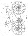
- Fig. 1 illustrates a bicycle 10 that includes a front wheel 12, a rear wheel 14, a frame 16, and a steering assembly 18.
- the frame 16 includes a top tube 20, a head tube 22, a down tube 24, a seat tube 26, seatstays 28, and chainstays 30.
- a bicycle seat assembly 32 is supported by the frame 16 and provides a surface upon which a rider sits while riding the bicycle 10.
- the bicycle seat assembly 32 includes a bicycle seat 34 supported by a bicycle seat support 36.
- the illustrated bicycle seat 34 is a standard seat having a contoured upper surface for supporting the rider, and lower rails 40 adapted to be secured to the bicycle seat support 36.
- the bicycle seat support 36 includes an upper engagement member 42 engaged with and supporting the lower rails 40, a lower engagement member 44 secured to and supported by the seat tube 26 of the frame 16, a compliant support assembly connecting the upper engagement member 42 to the lower engagement member 44, and an angular adjustment mechanism that adjusts the angle of the upper engagement member 42 relative to the compliant support assembly.
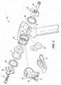
- the illustrated upper engagement member 42 ( Fig. 6 ) includes a cylindrical mount 45, two bearings 46, a support spool 47, two clamp members 48, and fasteners 49.
- the support spool 47 and clamp members 48 cooperatively define longitudinal recesses 50 ( Figs. 3 and 7 ) for receiving and clamping the lower rails 40 of the bicycle seat 34.
- the bearings 46 are operatively positioned between the support spool 47 and the cylindrical mount 46 such that the support spool 47 and clamps 48 are rotationally mounted to the cylindrical mount 46. Because the seat 34 is secured to the support spool 47 and clamps 48, the seat is similarly rotationally supported by the cylindrical mount 46.
- the illustrated lower engagement member 44 comprises a cylindrical seat post 52 secured inside the seat tube 26 of the frame 16 by a clamp 54 ( Fig. 1 ).
- the seat post 52 defines a lower axis 55 (see Fig. 2 ). It should be understood that the lower engagement member 44 could instead comprise any other structure for supporting the bicycle seat support 36 relative to the frame 16.
- the illustrated compliant support assembly includes a first cantilevered beam 56 defining a first axis 57, a second cantilevered beam 58 defining a second axis 59 and spaced from the first cantilevered beam 56 to define a gap 60, and a resilient member 62 positioned in the gap 60.
- the first cantilevered beam 56 includes a proximal portion cantilevered to the lower engagement member 44
- the second cantilevered beam 58 includes a proximal portion cantilevered to a distal portion of the first cantilevered beam 56.
- a distal portion of the second cantilevered beam is secured to the cylindrical mount 45 of the upper engagement member 42.
- the first axis 57 is positioned at an angle ⁇ of about seventy-five degrees relative to the lower axis 55 of the seat post 52, and the second axis 59 is positioned at an angle ⁇ of about forty-seven degrees relative to the first axis 57.
- Each of the first and second cantilevered beams 56, 58 comprises a composite material (e.g., carbon fibers in an epoxy matrix) that is sufficiently flexible to resiliently support a rider positioned on the bicycle seat 34.
- the first cantilevered beam 56 is formed integrally with the lower engagement member 44 as a one-piece molded composite member.
- the illustrated second cantilevered beam 58 and cylindrical mount 45 are integrally formed of a resilient material, such as titanium, steel, or another alloy having sufficient shape memory characteristics, and are secured to the first cantilevered beam 56 as a secondary operation, such as by bonding. Flexing of the cantilevered springs 56, 58 results in vertical movement of the seat 34, and very little horizontal movement of the seat 34.
- the second cantilevered beam 58 includes a pair of parallel-oriented alloy plates (e.g., steel, titanium, or another alloy having sufficient shape-memory characteristics).
- the illustrated angular adjustment mechanism includes a lower link 67 and an intermediate link 68.
- the lower link 67 is pivotally mounted to a lower pivot mount 69 (e.g., by a fastener, such as a cotter pin or bolt) on an upper surface of the lower engagement member 44.
- the intermediate link 68 includes a lower end that is pivotally coupled to the lower link 67 and an upper end that is secured to and movable with the support spool 47.
- a cantilevered four-bar linkage is created by the first cantilevered beam 56, the second cantilevered beam 58, the intermediate link 68, and the lower link 67 (see Fig. 2 ).
- This arrangement is designed to substantially maintain an angular orientation of the support spool 47 (and the attached seat 34) relative to the seat post 52.
- the connection between the intermediate link 68 and the support spool 47 is adjustable so that the static angular position of the seat 34 relative to the seat post 52 can be adjusted.
- the upper end of the intermediate link 68 includes a clamp 70 with a fastener 71 that can be tightened onto the support spool 47 at any of a number of different angular orientations.
- the fastener 71 is loosened to thereby loosen the engagement of the clamp 70 on the support spool 47.
- the seat 34 can then be tilted to the desired angle, resulting in rotational movement of the support spool 47 relative to the clamp 70.
- the fastener 71 can then be tightened to secure the intermediate member 68 to the support spool 47.
- the resilient member 62 provides additional resilient support to the bicycle seat 34.
- the resilient member 62 comprises a polyurethane elastomer having a hardness less than the hardness of the cantilevered beams 56, 58.
- the resilient member 62 is permanently secured in the gap 60, such as by adhesive.
- the resilient member 62 can be held in place in any other appropriate manner, such as using an interference fit, mechanical engagement, or fasteners.
- the resilient member 62 can be secured in the gap in such a manner that it can be removed from the gap 60 by the user so that a different resilient member can be used.
- a replacement resilient member can be substituted.
- a resilient member having a different stiffness can be used.
- a resilient member having less resiliency can be substituted into the gap 60.
- Such a replacement resilient member could use a stiffer material or a thicker cross section, for example.
- the bicycle seat support 36 operates in the following manner. As the bicycle encounters a bump, the frame 16 and seat post 52 will be forced upward. Such upward movement will be at least partially absorbed by the resilient member 62.
- the angular adjustment mechanism defines a four-bar linkage that serves to inhibit angular rotation of the seat 34 relative to the seat post 52 during the shock absorption. Specifically, as the seat 34 moves downward relative to the seat post 52, the lower link 67 and intermediate link 68 serve to inhibit the seat 34 from tilting rearward a substantial amount. In this manner, the user will feel securely positioned on the seat.
- Figs. 8-16 illustrate another bicycle seat support 100 for supporting the bicycle seat 34.
- the bicycle seat support 100 includes an upper engagement member 104 engaged with and supporting the lower rails 40 of a bicycle seat, a lower engagement member 108 secured to and supported by the seat tube 26 of the frame 16, and a compliant support assembly 112 connecting the upper engagement member 104 to the lower engagement member 108.
- the illustrated upper engagement member 104 includes a mount or base 116 and clamp members 120.
- Each of the clamp members 120 includes a first clamp 124 and a second clamp 128 that cooperatively define longitudinal recesses 132 for receiving and clamping the lower rails 40 of the bicycle seat.
- each second clamp 128 is partially seated or nested in the corresponding first clamp 124.
- Each of the first clamps 124 has a base portion 136 that is engaged with the base 116 within a cylindrical cavity 140 disposed on a lateral side of the base 116.
- Fasteners e.g., like the fasteners 49 illustrated in Fig. 6
- the base 116 also includes a detachable wear plate 142, a first pivot support 144 that extends generally upward from a central portion of the base 116, and a second pivot support 148 that extends generally downward from the central portion.
- the first pivot support 144 is defined by two first arms or posts 144a, 144b that are spaced apart from each other in the lateral direction.
- the second pivot support 148 is defined by two second arms or posts 148a, 148b that are spaced apart from each other in the lateral direction.
- the first posts 144a, 144b have holes 154 and the second posts 148a, 148b have holes 152, with one of the illustrated holes 152, 154 for each pivot support 144, 148 being threaded and the other hole 152, 154 in each post pair being unthreaded (e.g., with a countersink).
- the illustrated lower engagement member 108 has a seat post plug 156 that can be secured inside a seat post (not shown in Figs. 8-12 ), which can be attached to the seat tube 26 of the frame 16 by a clamp ( Fig. 1 ), as is known in the art.
- the lower engagement member defines a lower axis 160 and has an upper beam opening 164, a lower beam opening 168, and a central beam opening 172 that is disposed between the upper and lower beam openings 164, 168.
- the upper and lower beam openings 164, 168 are elongated laterally (i.e. the beam openings 164, 168 are elongated across the lower axis 160).
- the illustrated central beam opening 172 is square or nearly square in cross section.
- the central beam opening 172 preferably has a ratio of height-to-width that is closer to 1:1 than a ratio defined by the height-to-width of the upper or lower beam opening 164, 168.
- the lower engagement member 108 can have one or more additional cavities 176 (one shown) that reduces the overall weight of the lower engagement member 108.
- the illustrated compliant support assembly includes a first cantilevered beam 180 that defines a first axis 184 ( Figs. 14-16 ), and a second cantilevered beam 188 that defines a second axis 192 and that is spaced from the first cantilevered beam 180 to define a gap.
- Each of the first axis 184 and the second axis 192 is defined as a straight line or plane extending through the ends of the respective beams 180, 188.
- the illustrated first and second beams 180, 188 are the same, and each of the first and second beams 180, 188 has a proximal portion 196 that is cantilevered to the lower engagement member 108 within one of the respective upper and lower beam openings 164, 168.
- each cantilevered beam 180, 188 can be frictionally-fit within the openings 164, 168 in the lower engagement member 108 with or without adhesive to secure the beams 180, 188 in place.
- a distal portion 200 of each of the first and second cantilevered beams 180, 188 defines a hollow pivot that is attached to the base 116 by fasteners 202.
- the first and second cantilevered beams 180, 188 taper (i.e. become thinner) from the proximal portion 196 toward the distal portion 200.
- the first and second beams 180, 188 are formed of a resilient material (e.g., a composite such as carbon fibers in an epoxy matrix, a metal or metal alloy such as titanium, steel, or another alloy having sufficient shape memory characteristics, etc.) that is sufficiently flexible to resiliently support a rider positioned on the bicycle seat 34.
- the beams 180, 188 can have different resiliencies or rates of deflection (e.g., one beam can be thinner or thicker than the other or the beams can be formed of different materials, etc.).
- a bearing 204 is disposed in the pivot of each distal portion 200, and caps or spacers 208 encapsulate opposite ends of the bearings 204 to support the bearing within the pivot.
- the spacers 208 also define bearing surfaces so that the bearings 204 can rotate relative to the beams 180, 188.
- the first beam 180 extends over the central portion of the base 116, and the distal portion 200 of the first beam 180 is pivotally attached to the base 116 by a fastener 202 that attaches to the first posts 144a, 144b and that extends through the corresponding bearing 204.
- the fastener 202 is threaded into one of the first posts 144a.
- the second beam 188 extends below the central portion of the base 116, and the distal portion 200 of the second beam 188 is pivotally attached to the base 116 by another fastener 202 that attaches to the second posts 148a, 148b and that extends through the corresponding bearing 204.
- the fastener 202 for the second beam 188 is threaded into one of the second posts 148a.
- the compliant support assembly 112 also includes a bottom out beam in the form of a third cantilevered beam 212 that is positioned in a gap between the first and second cantilevered beams 180, 188.
- the third beam 212 has an axis 216 that is defined as a straight line extending through the ends of the third beam 212.
- the third cantilevered beam 212 has a proximal portion 220 that is cantilevered to the lower engagement member 108 within the central beam opening 172.
- the proximal portion 220 of the third cantilevered beam 212 can be frictionally-fit within the central opening in the lower engagement member 108 with or without adhesive to secure the beam 212 in place,
- the third cantilevered beam 212 tapers (i.e.
- the third beam 212 is formed of a resilient material (e.g., a composite such as carbon fibers in an epoxy matrix, a metal or metal allow such as titanium, steel, or another alloy having sufficient shape memory characteristics, etc.) that is sufficiently flexible to resiliently support a rider positioned on the bicycle seat 34.
- the material of the third beam 212 can be the same as or different from the material of the first and second beams 180, 188.
- the cross-sectional shape of the illustrated third beam 212 is generally squarer than the cross-sectional shape of the first and second beams 180, 188. Stated another way, the third beam 212 is generally less resilient (i.e. stiffer) than the first and second beams 180, 188.
- Fig. 14 illustrates the seat support 100 in an unflexed or unloaded position (i.e. a static position with no force or weight acting on or applied to the seat 34).
- the first, second, and third axes 184, 192, 216 are parallel to each other and generally perpendicular to the lower axis 160 of the seat post 108.
- the pivotal connection between the base 116 and the first and second beams 180, 188 effectively defines a double cantilevered four-bar linkage that supports the seat 34 in a level position.
- the third beam 212 is not in contact with the base 116 in the unflexed position.
- Fig. 15 illustrates the seat support 100 in an exemplary first flexed position due to a load being applied to the seat 34 (e.g., when a rider is seated on the bicycle 10 and the bicycle is encountering a bump).
- the load is transferred through the clamp members 120 to the first and second beams 180, 188, which flex a first amount (represented by a distance 228) under the load. Flexing of the cantilevered beams 180, 188 results in vertical movement of the seat 34 and very little horizontal movement or rotation of the seat 34 relative to the engagement member 108.
- the first and second axes 184, 192 are oriented at an obtuse angle relative to the lower axis 160. As shown in Fig.
- the load flexes the seat support (i.e. the first and second beams 180, 188 deflect) until the third beam 212 contacts the wear plate 142 on an underside of the base 116 in the first flexed position.
- the third beam 212 is not substantially flexed or deflected (i.e., the third axis 216 remains perpendicular to the lower axis), although the load sufficiently biases the seat support 100 downward such that the third beam 212 initially contacts the wear plate 142 on the underside of the base 16.
- Fig. 16 illustrates the seat support 100 in a second flexed position due to a larger load being applied to the seat 34.
- the load is transferred through the clamp members 120 to the first and second beams 180, 188, which flex a second amount (represented by a distance 232) under the larger load.
- the third beam 212 also flexes under the additional load an amount (represented by a distance 236).
- the wear plate 142 which can be formed of a material that is different from the base 116, limits wear on or damage to the base 116. Flexing of the cantilevered beams 180, 188 results in additional vertical movement of the seat 34 and very little horizontal movement or rotation of the seat 34.
- the first and second axes 184, 192 are oriented at a larger obtuse angle relative to the lower axis 160.
- the third beam 212 with its higher resistance to deflection, provides additional resilient support to the seat 34 in order to prevent over-stressing the first and second beams 180,188. It will be appreciated that the seat support 100 can be flexed to numerous positions and that the first and second flexed positions illustrated in Figs. 15 and 16 are only two exemplary flexed positions.
- the pivotal connection between the compliant support assembly 112 and the base 116 keeps the seat 34 substantially level in the unflexed position and in each flexed position. Stated another way, the seat support 100 allows the base 116 to pivot or rotate relative to the distal portions 200 of the first and second beams 180, 188 when a load is applied to the seat 34.
- the third beam 212 comes into contact with the base 116 at a given deflection, which is dependent on the resiliency or deflection of the first and second beams 180, 188.
- the third beam 212 is stiffer such that the deflection or spring rate of the compliant support assembly 112 increases compared to the deflection or spring rate defined only by the first and second beams 180, 188.
- the spring rate is linear before and after the third beam 212 comes into contact with the base 116, but the spring rate increases in magnitude when the third beam 212 makes contact, 188.
- the spring rate defined by the first and second beams 180, 188, and the spring rate defined by the third beam 212 can be adjusted by switching out the respective beams with other beams that have a higher or lower deflection rate, depending on the amount of deflection per unit of load that is desired.
Abstract
Description
- The present invention relates to bicycle seats, and particularly to resilient seat supports.
- Bicycles commonly have resilient seat supports that cushion the rider from vibrations and bumps while riding. Resilient seat supports commonly include coil springs or resilient pads positioned between a seat and a seat post.
- Resilient seat supports commonly include a resilient pivoting arrangement that facilitates pivoting of the seat about a pivot axis near the front of the seat. One disadvantage of such pivoting arrangements is that the angle of the seat relative to the bicycle frame changes by several degrees when the seat is pivoting to absorb a shock.
- The present invention provides a bicycle seat support comprising a lower engagement member adapted to engage a bicycle frame, an upper engagement member adapted to support a bicycle seat (e.g., defining longitudinal recesses for receiving and clamping a bicycle seat), and a compliant support assembly coupling the upper engagement member to the lower engagement member. The upper engagement member is mounted for rotation relative to the lower engagement member. For example, rotational bearings can be operatively positioned between the upper engagement member and the lower engagement member.
- In one embodiment, the bicycle seat support further comprises an angular adjustment mechanism coupled to the upper engagement member and configured to adjust an angle of the upper engagement member relative to the lower engagement member. For example, the angular adjustment mechanism can comprise a lower link coupled to the lower engagement member and an intermediate link coupled between the lower link and the upper engagement member. Preferably, the intermediate link is secured to the upper engagement member in one of a plurality of adjustable positions.
- The compliant support assembly can include a beam cantilevered to the lower engagement member and pivotally coupled to the upper engagement member, and the angular adjustment mechanism can be arranged to adjust an angle of the upper engagement member relative to the beam. Preferably, the beam is a first beam and the angular adjustment mechanism comprises a second beam coupled (e.g., cantilevered) to the lower engagement member and an intermediate link coupled (e.g., pivotally) between the first and second beams. In this manner, the lower engagement member, the first beam, the intermediate link, and the second beam can define a double cantilevered four bar linkage. In one embodiment, the seat support further comprises a bottom out beam cantilevered to the lower engagement member with a space between the bottom out beam and the upper engagement member. The bottom out beam is positioned to inhibit downward movement of the upper engagement member relative to the lower engagement member after the upper engagement member has deflected downward relative to the lower engagement member.
- Other aspects of the invention will become apparent by consideration of the detailed description and accompanying drawings.
-
-
Fig. 1 illustrates a side view of a bicycle having a bicycle seat assembly embodying the present invention and including a bicycle seat supported by a bicycle seat support. -
Fig. 2 is a side view of the bicycle seat support ofFig. 1 . -
Fig. 3 is a rear view of the bicycle seat support ofFig. 1 . -
Fig. 4 is a rear perspective view of the bicycle seat support ofFig. 1 . -
Fig. 5 is a front perspective view of the bicycle seat support ofFig. 1 . -
Fig. 6 is an exploded view of the bicycle seat support ofFig. 1 . -
Fig. 7 is a section view taken along line 7-7 inFig. 2 . -
Fig. 8 is a rear perspective view of another bicycle seat support for the bicycle ofFig. 1 . -
Fig. 9 is another rear perspective view of the bicycle seat support ofFig. 8 . -
Fig. 10 is a front perspective view of the bicycle seat support ofFig. 8 . -
Fig. 11 is a side view of the bicycle seat support ofFig. 8 . -
Fig. 12 is an exploded view of the bicycle seat support ofFig. 8 . -
Fig. 13 is a section view of the bicycle seat support taken along line 13-13 inFig, 10 . -
Fig. 14 is a side view of the bicycle seat support ofFig. 8 illustrating the seat support in an unflexed position. -
Fig. 15 is a side view of the bicycle seat support ofFig. 8 illustrating the seat support in a first flexed position. -
Fig. 16 is a side view of the bicycle seat support ofFig. 8 illustrating the seat support in a second flexed position. - Before any embodiments of the invention are explained in detail, it is to be understood that the invention is not limited in its application to the details of construction and the arrangement of components set forth in the following description or illustrated in the following drawings. The invention is capable of other embodiments and of being practiced or of being carried out in various ways.
-
Fig. 1 illustrates abicycle 10 that includes afront wheel 12, arear wheel 14, aframe 16, and asteering assembly 18. Theframe 16 includes atop tube 20, ahead tube 22, adown tube 24, aseat tube 26,seatstays 28, andchainstays 30. Abicycle seat assembly 32 is supported by theframe 16 and provides a surface upon which a rider sits while riding thebicycle 10. Thebicycle seat assembly 32 includes abicycle seat 34 supported by abicycle seat support 36. The illustratedbicycle seat 34 is a standard seat having a contoured upper surface for supporting the rider, andlower rails 40 adapted to be secured to thebicycle seat support 36. - Referring to
Figs. 2-7 , thebicycle seat support 36 includes anupper engagement member 42 engaged with and supporting thelower rails 40, alower engagement member 44 secured to and supported by theseat tube 26 of theframe 16, a compliant support assembly connecting theupper engagement member 42 to thelower engagement member 44, and an angular adjustment mechanism that adjusts the angle of theupper engagement member 42 relative to the compliant support assembly. - The illustrated upper engagement member 42 (
Fig. 6 ) includes acylindrical mount 45, twobearings 46, asupport spool 47, twoclamp members 48, andfasteners 49. Thesupport spool 47 andclamp members 48 cooperatively define longitudinal recesses 50 (Figs. 3 and7 ) for receiving and clamping thelower rails 40 of thebicycle seat 34. Thebearings 46 are operatively positioned between thesupport spool 47 and thecylindrical mount 46 such that thesupport spool 47 andclamps 48 are rotationally mounted to thecylindrical mount 46. Because theseat 34 is secured to thesupport spool 47 andclamps 48, the seat is similarly rotationally supported by thecylindrical mount 46. - The illustrated
lower engagement member 44 comprises acylindrical seat post 52 secured inside theseat tube 26 of theframe 16 by a clamp 54 (Fig. 1 ). Theseat post 52 defines a lower axis 55 (seeFig. 2 ). It should be understood that thelower engagement member 44 could instead comprise any other structure for supporting thebicycle seat support 36 relative to theframe 16. - Referring to
Fig. 2 , the illustrated compliant support assembly includes a first cantileveredbeam 56 defining afirst axis 57, a second cantileveredbeam 58 defining asecond axis 59 and spaced from the first cantileveredbeam 56 to define agap 60, and aresilient member 62 positioned in thegap 60. The firstcantilevered beam 56 includes a proximal portion cantilevered to thelower engagement member 44, and the secondcantilevered beam 58 includes a proximal portion cantilevered to a distal portion of the firstcantilevered beam 56. A distal portion of the second cantilevered beam is secured to thecylindrical mount 45 of theupper engagement member 42. - The
first axis 57 is positioned at an angle Φ of about seventy-five degrees relative to thelower axis 55 of theseat post 52, and thesecond axis 59 is positioned at an angle β of about forty-seven degrees relative to thefirst axis 57. Each of the first and secondcantilevered beams bicycle seat 34. In the illustrated embodiment, the firstcantilevered beam 56 is formed integrally with thelower engagement member 44 as a one-piece molded composite member. The illustrated second cantileveredbeam 58 andcylindrical mount 45 are integrally formed of a resilient material, such as titanium, steel, or another alloy having sufficient shape memory characteristics, and are secured to the first cantileveredbeam 56 as a secondary operation, such as by bonding. Flexing of thecantilevered springs seat 34, and very little horizontal movement of theseat 34. In another example, the secondcantilevered beam 58 includes a pair of parallel-oriented alloy plates (e.g., steel, titanium, or another alloy having sufficient shape-memory characteristics). - The illustrated angular adjustment mechanism includes a
lower link 67 and anintermediate link 68. Thelower link 67 is pivotally mounted to a lower pivot mount 69 (e.g., by a fastener, such as a cotter pin or bolt) on an upper surface of thelower engagement member 44. Theintermediate link 68 includes a lower end that is pivotally coupled to thelower link 67 and an upper end that is secured to and movable with thesupport spool 47. By virtue of this arrangement, a cantilevered four-bar linkage is created by the firstcantilevered beam 56, the secondcantilevered beam 58, theintermediate link 68, and the lower link 67 (seeFig. 2 ). This arrangement is designed to substantially maintain an angular orientation of the support spool 47 (and the attached seat 34) relative to theseat post 52. - The connection between the
intermediate link 68 and thesupport spool 47 is adjustable so that the static angular position of theseat 34 relative to theseat post 52 can be adjusted. Specifically, the upper end of theintermediate link 68 includes aclamp 70 with afastener 71 that can be tightened onto thesupport spool 47 at any of a number of different angular orientations. In order to adjust the angle of theseat 34, thefastener 71 is loosened to thereby loosen the engagement of theclamp 70 on thesupport spool 47. Theseat 34 can then be tilted to the desired angle, resulting in rotational movement of thesupport spool 47 relative to theclamp 70. When the desired seat angle is achieved, thefastener 71 can then be tightened to secure theintermediate member 68 to thesupport spool 47. - The
resilient member 62 provides additional resilient support to thebicycle seat 34. Theresilient member 62 comprises a polyurethane elastomer having a hardness less than the hardness of the cantilevered beams 56, 58. In the preferred embodiment, theresilient member 62 is permanently secured in thegap 60, such as by adhesive. Alternatively, theresilient member 62 can be held in place in any other appropriate manner, such as using an interference fit, mechanical engagement, or fasteners. - In an alternative embodiment, the
resilient member 62 can be secured in the gap in such a manner that it can be removed from thegap 60 by the user so that a different resilient member can be used. For example, if theresilient member 62 becomes damaged or worn, a replacement resilient member can be substituted. Alternatively, if it is desired to achieve a different resiliency, a resilient member having a different stiffness can be used. For example, if it desired to increase the stiffness of thecompliant support assembly 46, a resilient member having less resiliency can be substituted into thegap 60. Such a replacement resilient member could use a stiffer material or a thicker cross section, for example. - In use, the
bicycle seat support 36 operates in the following manner. As the bicycle encounters a bump, theframe 16 and seat post 52 will be forced upward. Such upward movement will be at least partially absorbed by theresilient member 62. As noted above, the angular adjustment mechanism defines a four-bar linkage that serves to inhibit angular rotation of theseat 34 relative to theseat post 52 during the shock absorption. Specifically, as theseat 34 moves downward relative to theseat post 52, thelower link 67 andintermediate link 68 serve to inhibit theseat 34 from tilting rearward a substantial amount. In this manner, the user will feel securely positioned on the seat. -
Figs. 8-16 illustrate anotherbicycle seat support 100 for supporting thebicycle seat 34. Thebicycle seat support 100 includes anupper engagement member 104 engaged with and supporting thelower rails 40 of a bicycle seat, alower engagement member 108 secured to and supported by theseat tube 26 of theframe 16, and acompliant support assembly 112 connecting theupper engagement member 104 to thelower engagement member 108. As shown inFigs. 8-10 and12 , the illustratedupper engagement member 104 includes a mount orbase 116 andclamp members 120. Each of theclamp members 120 includes afirst clamp 124 and asecond clamp 128 that cooperatively definelongitudinal recesses 132 for receiving and clamping thelower rails 40 of the bicycle seat. As illustrated inFig. 13 , eachsecond clamp 128 is partially seated or nested in the correspondingfirst clamp 124. - Each of the
first clamps 124 has abase portion 136 that is engaged with thebase 116 within acylindrical cavity 140 disposed on a lateral side of thebase 116. Fasteners (e.g., like thefasteners 49 illustrated inFig. 6 ) attach theclamp members 120 to thebase 116. With reference toFigs. 8-12 , thebase 116 also includes adetachable wear plate 142, afirst pivot support 144 that extends generally upward from a central portion of thebase 116, and asecond pivot support 148 that extends generally downward from the central portion. Thefirst pivot support 144 is defined by two first arms orposts second pivot support 148 is defined by two second arms orposts first posts holes 154 and thesecond posts holes 152, with one of the illustratedholes pivot support other hole - The illustrated
lower engagement member 108 has aseat post plug 156 that can be secured inside a seat post (not shown inFigs. 8-12 ), which can be attached to theseat tube 26 of theframe 16 by a clamp (Fig. 1 ), as is known in the art. Referring toFigs. 12 and14-16 , the lower engagement member defines alower axis 160 and has anupper beam opening 164, alower beam opening 168, and acentral beam opening 172 that is disposed between the upper andlower beam openings lower beam openings beam openings central beam opening 172 is square or nearly square in cross section. In general, thecentral beam opening 172 preferably has a ratio of height-to-width that is closer to 1:1 than a ratio defined by the height-to-width of the upper orlower beam opening lower engagement member 108 can have one or more additional cavities 176 (one shown) that reduces the overall weight of thelower engagement member 108. - The illustrated compliant support assembly includes a first
cantilevered beam 180 that defines a first axis 184 (Figs. 14-16 ), and a secondcantilevered beam 188 that defines asecond axis 192 and that is spaced from the firstcantilevered beam 180 to define a gap. Each of thefirst axis 184 and thesecond axis 192 is defined as a straight line or plane extending through the ends of therespective beams second beams second beams proximal portion 196 that is cantilevered to thelower engagement member 108 within one of the respective upper andlower beam openings proximal portion 196 of eachcantilevered beam openings lower engagement member 108 with or without adhesive to secure thebeams distal portion 200 of each of the first and secondcantilevered beams base 116 byfasteners 202. - With reference to
Figs. 11 and14-16 , the first and secondcantilevered beams proximal portion 196 toward thedistal portion 200. The first andsecond beams bicycle seat 34. Although the illustratedbeams beams - A
bearing 204 is disposed in the pivot of eachdistal portion 200, and caps orspacers 208 encapsulate opposite ends of thebearings 204 to support the bearing within the pivot. Thespacers 208 also define bearing surfaces so that thebearings 204 can rotate relative to thebeams - The
first beam 180 extends over the central portion of thebase 116, and thedistal portion 200 of thefirst beam 180 is pivotally attached to thebase 116 by afastener 202 that attaches to thefirst posts bearing 204. Thefastener 202 is threaded into one of thefirst posts 144a. Thesecond beam 188 extends below the central portion of thebase 116, and thedistal portion 200 of thesecond beam 188 is pivotally attached to thebase 116 by anotherfastener 202 that attaches to thesecond posts bearing 204. Thefastener 202 for thesecond beam 188 is threaded into one of thesecond posts 148a. - The
compliant support assembly 112 also includes a bottom out beam in the form of a thirdcantilevered beam 212 that is positioned in a gap between the first and secondcantilevered beams third beam 212 has anaxis 216 that is defined as a straight line extending through the ends of thethird beam 212. The thirdcantilevered beam 212 has aproximal portion 220 that is cantilevered to thelower engagement member 108 within thecentral beam opening 172. Theproximal portion 220 of the thirdcantilevered beam 212 can be frictionally-fit within the central opening in thelower engagement member 108 with or without adhesive to secure thebeam 212 in place, The thirdcantilevered beam 212 tapers (i.e. becomes narrower) from theproximal portion 220 toward adistal portion 224. Thethird beam 212 is formed of a resilient material (e.g., a composite such as carbon fibers in an epoxy matrix, a metal or metal allow such as titanium, steel, or another alloy having sufficient shape memory characteristics, etc.) that is sufficiently flexible to resiliently support a rider positioned on thebicycle seat 34. The material of thethird beam 212 can be the same as or different from the material of the first andsecond beams third beam 212 is generally squarer than the cross-sectional shape of the first andsecond beams third beam 212 is generally less resilient (i.e. stiffer) than the first andsecond beams -
Fig. 14 illustrates theseat support 100 in an unflexed or unloaded position (i.e. a static position with no force or weight acting on or applied to the seat 34). In the first position, the first, second, andthird axes lower axis 160 of theseat post 108. The pivotal connection between the base 116 and the first andsecond beams seat 34 in a level position. Thethird beam 212 is not in contact with the base 116 in the unflexed position. -
Fig. 15 illustrates theseat support 100 in an exemplary first flexed position due to a load being applied to the seat 34 (e.g., when a rider is seated on thebicycle 10 and the bicycle is encountering a bump). The load is transferred through theclamp members 120 to the first andsecond beams beams seat 34 and very little horizontal movement or rotation of theseat 34 relative to theengagement member 108. In the first flexed position, the first andsecond axes lower axis 160. As shown inFig. 15 , the load flexes the seat support (i.e. the first andsecond beams third beam 212 contacts thewear plate 142 on an underside of the base 116 in the first flexed position. In the illustrated first flexed position, thethird beam 212 is not substantially flexed or deflected (i.e., thethird axis 216 remains perpendicular to the lower axis), although the load sufficiently biases theseat support 100 downward such that thethird beam 212 initially contacts thewear plate 142 on the underside of thebase 16. -
Fig. 16 illustrates theseat support 100 in a second flexed position due to a larger load being applied to theseat 34. The load is transferred through theclamp members 120 to the first andsecond beams third beam 212 also flexes under the additional load an amount (represented by a distance 236). Thewear plate 142, which can be formed of a material that is different from thebase 116, limits wear on or damage to thebase 116. Flexing of the cantileveredbeams seat 34 and very little horizontal movement or rotation of theseat 34. In the illustrated second flexed position, the first andsecond axes lower axis 160. In general, thethird beam 212, with its higher resistance to deflection, provides additional resilient support to theseat 34 in order to prevent over-stressing the first and second beams 180,188. It will be appreciated that theseat support 100 can be flexed to numerous positions and that the first and second flexed positions illustrated inFigs. 15 and 16 are only two exemplary flexed positions. - The pivotal connection between the
compliant support assembly 112 and thebase 116 keeps theseat 34 substantially level in the unflexed position and in each flexed position. Stated another way, theseat support 100 allows the base 116 to pivot or rotate relative to thedistal portions 200 of the first andsecond beams seat 34. Thethird beam 212 comes into contact with the base 116 at a given deflection, which is dependent on the resiliency or deflection of the first andsecond beams third beam 212 is stiffer such that the deflection or spring rate of thecompliant support assembly 112 increases compared to the deflection or spring rate defined only by the first andsecond beams third beam 212 comes into contact with thebase 116, but the spring rate increases in magnitude when thethird beam 212 makes contact, 188. The spring rate defined by the first andsecond beams third beam 212, can be adjusted by switching out the respective beams with other beams that have a higher or lower deflection rate, depending on the amount of deflection per unit of load that is desired. - Various features and advantages of the invention are set forth in the following claims.
Claims (15)
- A bicycle seat support comprising:a lower engagement member adapted to engage a bicycle frame;an upper engagement member adapted to support a bicycle seat, wherein the upper engagement member is mounted for rotation relative to the lower engagement member; anda compliant support assembly coupling the upper engagement member to the lower engagement member.
- A bicycle seat support as claimed in claim 1, further comprising rotational bearings operatively positioned between the upper engagement member and the lower engagement member.
- A bicycle seat support as claimed in claim 1, wherein the upper engagement member defines longitudinal recesses for receiving and clamping a bicycle seat.
- A bicycle seat support as claimed in claim 1, further comprising an angular adjustment mechanism coupled to the upper engagement member and configured to adjust an angle of the upper engagement member relative to the lower engagement member.
- A bicycle seat support as claimed in claim 4, wherein the angular adjustment mechanism comprises a lower link coupled to the lower engagement member and an intermediate link coupled between the lower link and the upper engagement member.
- A bicycle seat support as claimed in claim 5, wherein the intermediate link is secured to the upper engagement member in one of a plurality of adjustable positions.
- A bicycle seat support as claimed in claim 5, wherein the intermediate link is secured to the upper engagement member.
- A bicycle seat support as claimed in claim 7, wherein the compliant support assembly includes a cantilevered beam and wherein the intermediate link pivotally connects the cantilevered beam and the lower link.
- A bicycle seat support comprising:an upper engagement member adapted to support a bicycle seat;a lower engagement member adapted to engage a bicycle frame;a beam cantilevered to the lower engagement member and pivotally coupled to the upper engagement member; andan angular adjustment mechanism that adjusts an angle of the upper engagement member relative to the beam.
- A bicycle seat support as claimed in claim 9, wherein the upper engagement member defines longitudinal recesses for receiving and clamping a bicycle seat.
- A bicycle seat support as claimed in claim 9, wherein the beam is a first beam and wherein the angular adjustment mechanism comprises:a second beam coupled to the lower engagement member; andan intermediate link coupled between the second beam and the upper engagement member.
- A bicycle seat support as claimed in claim 11, wherein the second beam is cantilevered to the lower engagement member.
- A bicycle seat support as claimed in claim 12, wherein the second beam is pivotally coupled to the intermediate link.
- A bicycle seat support as claimed in claim 13, wherein the lower engagement member, the first beam, the intermediate link, and the second beam define a double cantilevered four bar linkage.
- A bicycle seat support as claimed in claim 9, wherein the seat support further comprises a bottom out beam cantilevered to the lower engagement member with a space between the bottom out beam and the upper engagement member, the bottom out beam being positioned to inhibit downward movement of the upper engagement member relative to the lower engagement member after the upper engagement member has deflected downward relative to the lower engagement member.
Applications Claiming Priority (2)
| Application Number | Priority Date | Filing Date | Title |
|---|---|---|---|
| US201562151009P | 2015-04-22 | 2015-04-22 | |
| US201562245508P | 2015-10-23 | 2015-10-23 |
Publications (1)
| Publication Number | Publication Date |
|---|---|
| EP3090932A1 true EP3090932A1 (en) | 2016-11-09 |
Family
ID=55802276
Family Applications (1)
| Application Number | Title | Priority Date | Filing Date |
|---|---|---|---|
| EP16166290.3A Withdrawn EP3090932A1 (en) | 2015-04-22 | 2016-04-21 | Bicycle seat with resilient support |
Country Status (3)
| Country | Link |
|---|---|
| US (1) | US20160311485A1 (en) |
| EP (1) | EP3090932A1 (en) |
| TW (1) | TW201704073A (en) |
Families Citing this family (2)
| Publication number | Priority date | Publication date | Assignee | Title |
|---|---|---|---|---|
| US10450022B2 (en) * | 2018-01-31 | 2019-10-22 | David Watson | Device for adjusting a seat position of a bicycle seat |
| CN112167299A (en) * | 2020-08-17 | 2021-01-05 | 寿王荣 | A vibrations formula of beating mechanism that is used for meat thick liquid production that possesses body-building function |
Citations (2)
| Publication number | Priority date | Publication date | Assignee | Title |
|---|---|---|---|---|
| TWM352491U (en) * | 2008-10-17 | 2009-03-11 | Hsin Lung Accessories Co Ltd | Bicycle seat cushion angle adjustment structure |
| US20110210231A1 (en) * | 2010-02-26 | 2011-09-01 | Specialized Bicycle Components, Inc. | Bicycle seat with resilient support |
Family Cites Families (1)
| Publication number | Priority date | Publication date | Assignee | Title |
|---|---|---|---|---|
| WO2013033674A1 (en) * | 2011-09-01 | 2013-03-07 | Cirrus Cycles, Inc. | Suspension systems and methods for bicycles |
-
2016
- 2016-04-21 EP EP16166290.3A patent/EP3090932A1/en not_active Withdrawn
- 2016-04-22 TW TW105112722A patent/TW201704073A/en unknown
- 2016-04-22 US US15/136,098 patent/US20160311485A1/en not_active Abandoned
Patent Citations (2)
| Publication number | Priority date | Publication date | Assignee | Title |
|---|---|---|---|---|
| TWM352491U (en) * | 2008-10-17 | 2009-03-11 | Hsin Lung Accessories Co Ltd | Bicycle seat cushion angle adjustment structure |
| US20110210231A1 (en) * | 2010-02-26 | 2011-09-01 | Specialized Bicycle Components, Inc. | Bicycle seat with resilient support |
Also Published As
| Publication number | Publication date |
|---|---|
| TW201704073A (en) | 2017-02-01 |
| US20160311485A1 (en) | 2016-10-27 |
Similar Documents
| Publication | Publication Date | Title |
|---|---|---|
| US4403784A (en) | Roller skate axle suspension | |
| US5489139A (en) | Parallel link seatpost suspension | |
| US8678339B2 (en) | Bicycle seat with resilient support | |
| US5286082A (en) | Anatomically compensating cycle saddle | |
| US6019422A (en) | Laterally pivoting bicycle saddle mount with shock absorber | |
| US1000115A (en) | Bicycle shock-absorber. | |
| US9604690B2 (en) | Bicycle frame with coupling device to permit flexing | |
| US8465027B2 (en) | Roller skate steering and suspension mechanism | |
| US20070039409A1 (en) | Pillar stem for aerobar assembly | |
| US10017082B2 (en) | Shock mitigation apparatus | |
| US6899389B2 (en) | Bicycle seat assembly | |
| US20110210231A1 (en) | Bicycle seat with resilient support | |
| US7478872B2 (en) | Seat assembly | |
| EP3090932A1 (en) | Bicycle seat with resilient support | |
| US20090212185A1 (en) | Motor mount for a vehicle | |
| US6270065B1 (en) | Seat suspension assembly for a two-wheeler | |
| WO1996038335A1 (en) | Spring-action seat suspension assembly for a two-wheeler | |
| US20120146304A1 (en) | Spring Resistant Riser System | |
| US9637156B2 (en) | Skiing apparatus | |
| CN101166660A (en) | Seat structure, particularly for cycle and human body support frames | |
| US20110115265A1 (en) | Bicycle Saddle | |
| US5911473A (en) | Bicycle saddle | |
| US470317A (en) | burton | |
| EP0669247A1 (en) | Rear suspension frame for two-wheeled vehicles | |
| FR2988069A1 (en) | ERGONOMIC AND DYNAMIC SEAT COMPRISING TWO SELLETS |
Legal Events
| Date | Code | Title | Description |
|---|---|---|---|
| PUAI | Public reference made under article 153(3) epc to a published international application that has entered the european phase |
Free format text: ORIGINAL CODE: 0009012 |
|
| AK | Designated contracting states |
Kind code of ref document: A1 Designated state(s): AL AT BE BG CH CY CZ DE DK EE ES FI FR GB GR HR HU IE IS IT LI LT LU LV MC MK MT NL NO PL PT RO RS SE SI SK SM TR |
|
| AX | Request for extension of the european patent |
Extension state: BA ME |
|
| 17P | Request for examination filed |
Effective date: 20170509 |
|
| RBV | Designated contracting states (corrected) |
Designated state(s): AL AT BE BG CH CY CZ DE DK EE ES FI FR GB GR HR HU IE IS IT LI LT LU LV MC MK MT NL NO PL PT RO RS SE SI SK SM TR |
|
| 17Q | First examination report despatched |
Effective date: 20181205 |
|
| STAA | Information on the status of an ep patent application or granted ep patent |
Free format text: STATUS: THE APPLICATION IS DEEMED TO BE WITHDRAWN |
|
| 18D | Application deemed to be withdrawn |
Effective date: 20190416 |