EP3090884A1 - Image board for rotation wheel and rotation wheel including same - Google Patents
Image board for rotation wheel and rotation wheel including same Download PDFInfo
- Publication number
- EP3090884A1 EP3090884A1 EP14867813.9A EP14867813A EP3090884A1 EP 3090884 A1 EP3090884 A1 EP 3090884A1 EP 14867813 A EP14867813 A EP 14867813A EP 3090884 A1 EP3090884 A1 EP 3090884A1
- Authority
- EP
- European Patent Office
- Prior art keywords
- wheel frame
- base plate
- wheel
- rotation
- image
- Prior art date
- Legal status (The legal status is an assumption and is not a legal conclusion. Google has not performed a legal analysis and makes no representation as to the accuracy of the status listed.)
- Withdrawn
Links
Images







Classifications
-
- B—PERFORMING OPERATIONS; TRANSPORTING
- B60—VEHICLES IN GENERAL
- B60B—VEHICLE WHEELS; CASTORS; AXLES FOR WHEELS OR CASTORS; INCREASING WHEEL ADHESION
- B60B7/00—Wheel cover discs, rings, or the like, for ornamenting, protecting, venting, or obscuring, wholly or in part, the wheel body, rim, hub, or tyre sidewall, e.g. wheel cover discs, wheel cover discs with cooling fins
- B60B7/0026—Wheel cover discs, rings, or the like, for ornamenting, protecting, venting, or obscuring, wholly or in part, the wheel body, rim, hub, or tyre sidewall, e.g. wheel cover discs, wheel cover discs with cooling fins characterised by the surface
- B60B7/0033—Wheel cover discs, rings, or the like, for ornamenting, protecting, venting, or obscuring, wholly or in part, the wheel body, rim, hub, or tyre sidewall, e.g. wheel cover discs, wheel cover discs with cooling fins characterised by the surface the dominant aspect being the surface appearance
- B60B7/0053—Wheel cover discs, rings, or the like, for ornamenting, protecting, venting, or obscuring, wholly or in part, the wheel body, rim, hub, or tyre sidewall, e.g. wheel cover discs, wheel cover discs with cooling fins characterised by the surface the dominant aspect being the surface appearance the surface being decorated
-
- B—PERFORMING OPERATIONS; TRANSPORTING
- B60—VEHICLES IN GENERAL
- B60B—VEHICLE WHEELS; CASTORS; AXLES FOR WHEELS OR CASTORS; INCREASING WHEEL ADHESION
- B60B7/00—Wheel cover discs, rings, or the like, for ornamenting, protecting, venting, or obscuring, wholly or in part, the wheel body, rim, hub, or tyre sidewall, e.g. wheel cover discs, wheel cover discs with cooling fins
- B60B7/04—Wheel cover discs, rings, or the like, for ornamenting, protecting, venting, or obscuring, wholly or in part, the wheel body, rim, hub, or tyre sidewall, e.g. wheel cover discs, wheel cover discs with cooling fins built-up of several main parts
-
- B—PERFORMING OPERATIONS; TRANSPORTING
- B60—VEHICLES IN GENERAL
- B60B—VEHICLE WHEELS; CASTORS; AXLES FOR WHEELS OR CASTORS; INCREASING WHEEL ADHESION
- B60B7/00—Wheel cover discs, rings, or the like, for ornamenting, protecting, venting, or obscuring, wholly or in part, the wheel body, rim, hub, or tyre sidewall, e.g. wheel cover discs, wheel cover discs with cooling fins
- B60B7/01—Rings specially adapted for covering only the wheel rim or the tyre sidewall, e.g. removable tyre sidewall trim rings
-
- B—PERFORMING OPERATIONS; TRANSPORTING
- B60—VEHICLES IN GENERAL
- B60B—VEHICLE WHEELS; CASTORS; AXLES FOR WHEELS OR CASTORS; INCREASING WHEEL ADHESION
- B60B7/00—Wheel cover discs, rings, or the like, for ornamenting, protecting, venting, or obscuring, wholly or in part, the wheel body, rim, hub, or tyre sidewall, e.g. wheel cover discs, wheel cover discs with cooling fins
- B60B7/06—Fastening arrangements therefor
- B60B7/061—Fastening arrangements therefor characterised by the part of the wheels to which the discs, rings or the like are mounted
- B60B7/066—Fastening arrangements therefor characterised by the part of the wheels to which the discs, rings or the like are mounted to the hub
-
- B—PERFORMING OPERATIONS; TRANSPORTING
- B60—VEHICLES IN GENERAL
- B60B—VEHICLE WHEELS; CASTORS; AXLES FOR WHEELS OR CASTORS; INCREASING WHEEL ADHESION
- B60B7/00—Wheel cover discs, rings, or the like, for ornamenting, protecting, venting, or obscuring, wholly or in part, the wheel body, rim, hub, or tyre sidewall, e.g. wheel cover discs, wheel cover discs with cooling fins
- B60B7/20—Wheel cover discs, rings, or the like, for ornamenting, protecting, venting, or obscuring, wholly or in part, the wheel body, rim, hub, or tyre sidewall, e.g. wheel cover discs, wheel cover discs with cooling fins having an element mounted for rotation independently of wheel rotation
-
- B—PERFORMING OPERATIONS; TRANSPORTING
- B60—VEHICLES IN GENERAL
- B60B—VEHICLE WHEELS; CASTORS; AXLES FOR WHEELS OR CASTORS; INCREASING WHEEL ADHESION
- B60B2200/00—Type of product being used or applied
- B60B2200/20—Furniture or medical appliances
- B60B2200/22—Chairs
-
- B—PERFORMING OPERATIONS; TRANSPORTING
- B60—VEHICLES IN GENERAL
- B60B—VEHICLE WHEELS; CASTORS; AXLES FOR WHEELS OR CASTORS; INCREASING WHEEL ADHESION
- B60B2900/00—Purpose of invention
- B60B2900/50—Improvement of
- B60B2900/572—Visual appearance
-
- B—PERFORMING OPERATIONS; TRANSPORTING
- B60—VEHICLES IN GENERAL
- B60Y—INDEXING SCHEME RELATING TO ASPECTS CROSS-CUTTING VEHICLE TECHNOLOGY
- B60Y2200/00—Type of vehicle
- B60Y2200/10—Road Vehicles
Definitions
- the present invention relates to an image board for a rotation wheel and a rotation wheel including the same and, more particularly, to an image board for a rotation wheel that is mounted on a rotation wheel of a vehicle such as a car or a bicycle and displays a still image regardless of rotation of the rotation wheel.
- FIGS. 1 to 3 show the configuration of an image board for a rotation wheel in the related art.
- an image board 10 for a rotation wheel in the related art is equipped with a weight 11 having predetermined weight at a lower portion and is rotatably mounted on a side of a wheel frame 20 of a car 1 by a bearing (not shown).
- An image I that may be various images including a logo, an emblem, or an advertising image is on the outer surface of the image board 10, so it is possible to achieve advertising and decorative effects as an accessory by keeping the image I in a stop state even though the wheel frame 20 is rotated while the car 1 runs.
- the weight 11 is eccentrically disposed at the lower portion of the image board 10, when the weight 11 is rotated along with the image board 10 due to malfunction of the bearing, vibration is generated by an eccentric weight change of the weight 11, in which the heavier the weight 11, the more the vibration increases. Further, the difference in weight applied on two rotation wheels disposed on the same shaft adversely influences steering function of the car 1, so it may cause a safety accident.
- the present invention is directed to providing an image board for a rotation wheel that can always display a still image even if a wheel is rotated at a high speed, using rotational inertia of an impeller and friction applied on the blades of the impeller, by mounting the impeller, which is rotated in opposite direction to the wheel by wind flowing inside when a vehicle runs, at a lower portion of an image board without eccentricity by a weight and the impeller, and a rotation wheel including the image board.
- One aspect of the present invention provides an image board for a rotation wheel that is mounted on a rotation wheel 200 of a vehicle 1 and displays a still image I regardless of rotation of the rotation wheel 200
- the image board includes: a base plate 110 that is vertically disposed outside or inside a wheel frame 210 mounted on the rotation wheel 200 to rotate independently from the wheel frame 210 and has a predetermined image I on one side or both sides; and an impeller 120 that is fastened to a lower portion of the base plate 110 and rotates in the opposite direction to the rotation wheel 200 by running wind that flows inside when the vehicle 1 runs;
- the image board may further include: a fastening plate 130 that is vertically fastened to an outer side of the wheel frame 210 and rotates along with the wheel frame 210; and a bearing assembly 140 that is fitted in the center of the fastening plate 130, in which the base plate 110 may be fitted on the bearing assembly 140 and vertically mounted on the outer side of the wheel frame 210 to be rotated independently from the wheel frame 210 by the bearing assembly 140.
- the image board may further include a bearing assembly 140 that is laterally fitted on a horizontal rotational shaft 211 of the wheel frame 210 by an inserting hole therein, in which and the base plate 110 may be fitted on the outer circumference of the bearing assembly 140 and vertically fitted inside the wheel frame 210 to be rotated independently from the wheel frame 210 by the bearing assembly 140.
- the rotation wheel includes: a wheel frame 210 that is fitted in a tire 212 and rotated by power; and an image board 100 including: a base plate 110 that is vertically disposed outside or inside the wheel frame 210 mounted on the wheel 200 to rotate independently from the wheel frame 210 and has a predetermined image I on one side or both sides; and
- the image I can be fixed and shown without rotating by inertia generated by rotation of the impeller 120 and friction on the blades 121 even though the wheel frame 210 rotates at a high speed while the vehicle 1 runs.
- the rotational speed of the impeller 120 is increased and the generated inertia force and the friction force are increased, it is possible to keep the image I fixed regardless of the rotational speed of the wheel frame 210.
- the eccentricity of the total weight of the image board 100 is prevented by the weights 160, so even if the weights 160 are rotated along with the base plate 110 due to malfunction of the bearing assembly 140, it is possible to preclude the problem that vibration is generated or steering function is adversely influenced by the eccentricity of the weights, thereby causing a safety accident.
- the compensating weight 170 having weight corresponding to the weight of the impeller 120 is disposed around the circumferential edge of the base plate 110, it is possible to compensate for the phenomenon that the total weight of the image board 100 concentrates on the impeller 120 mounted on the base plate 110.
- the bearing assembly 140 is composed of a plurality of bearings 141, 142, and 143 having different diameters and sequentially fitted in larger ones, torque F1 that rotates the image board 100 can be reduced by friction and inertia generated by rotation of the bearings 141, 142, and 143.
- bearing assembly 140 is composed of three bearings 141, 142, and 143 or more, rotation of the base plate 110 by the innermost bearing 141 and rotation of the wheel frame 210 by the outermost bearing 143 can be physically separated by the bearing 142 between the innermost bearing 141 and the outermost bearing 143, thereby further reducing the torque F1.
- a rotation wheel 200 according to an embodiment of the present invention which is mounted at a lower portion of a vehicle 1 for driving the vehicle 1 and is equipped with an image board 100 displaying a still image I regardless of rotation of the rotation wheel 200, includes a wheel frame 210 and the image board 100.
- the vehicle 1 can be moved by the rotation wheel 200 and the rotation wheel 200 has the wheel frame 210 on which the image board 100 can be mounted.
- the vehicle 1 includes a car, bicycle, and a cart, and other vehicles equipped with the rotation wheel 200 having the wheel frame 210 such as a motor cycle, a golf cart, a wheelchair, and a baby walker can all be applied to the present invention.
- the wheel frame 210 which is a part to be fitted in a tire 212 and rotated by power, is mounted with the image board 100 that can independently rotate, may be formed in an integrated type such as the wheel frames for cars or golf carts, depending on the type of the vehicle 1, and may be fitted on a rotary shaft (power shaft).
- the wheel frame 210 similar to those of a bicycle, a motor cycle, a wheelchair, and a cart, may include a rim 214 that is fitted in a tire 212, a rotational shaft 211 that is disposed at the center of the rim 214 and is rotated by torque supplied from a chain, and a plurality of spokes 215 that connects the rotational shaft 211 and the rim 214 to each other to support load.
- the image board 100 which is independently rotatably mounted on the wheel frame 210 to display a still image I regardless of rotation of the wheel frame 210, includes: a base plate 110 that is vertically disposed outside or inside the wheel frame 210 to rotate independently from the wheel frame 210 and has a predetermined image I on one side or both sides; and an impeller 120 that is fastened to a lower portion of the base plate 110 and rotates in the opposite direction to the wheel frame 210 by running wind that flows inside when the vehicle 1 runs.
- the image I which is an image designed in various types such as a logo, an emblem, or an advertising image, may be directly printed on the base plate 110, or may be implemented by attaching a printed sheet to the base plate 110 or by drawing an image on a specific image plate and then attaching the image plate to the base plate 110.
- the image I may be disposed on the outer side of the base plate 110, but when the wheel frame 210 is exposed at both sides such as a wheel for a bicycle, the image I may be disposed on both sides of the base plate 110, respectively, to increase the effect of exposing the image.
- the image board may further include: a fastening plate 130 that is vertically fastened to the outer side of the wheel frame 210 to rotate along with the wheel frame 210; and a bearing assembly 140 that is coupled to the center of the fastening plate 130.
- the base plate 110 may be coupled to the bearing assembly 140 and mounted vertically on the outside of the wheel frame 210 such that it can rotate independently from the wheel frame 210 by the bearing assembly 140.
- the edge of the base plate 110 is rounded and curved inward, so the bearing assembly 140 and the fastening plate 130 inside the base plate 110 are exposed as little as possible. Further, the air that flows over the base plate 110 when the vehicle 1 runs slides over the bent edge, so movement of the base plate 110 by the running wind can be reduced.
- the fastening plate 130 which is a plate vertically fastened to a side of the wheel frame 210 and supporting the base plate 110, is a circular plate that has a plurality of fastening holes 133 around the edge for inserting bolts 217 protruding from the wheel body 210 and a center hole 131 formed at the center to prevent interference with the bearing assembly 140 coupled to the fastening plate 130.
- the fastening holes 133 may be formed at a plurality of wings 132 protruding around the fastening plate 130 to reduce the size of the fastening plate 130.
- the fastening plate 130 can be firmly fastened to the wheel frame 210 by nuts 216 that are thread-fastened to the ends of the bolts 217 and press the portions around the fastening holes 113 of the fastening plate 130 vertically mounted on the side of the wheel frame 210 with the bots 217 inserted through the fastening holes 113.
- coupling tubes 213 that are fitted on the bolts 217 between the fastening plate 130 and the wheel frame 210 to support a side of the fastening plate 130 may be provided.
- a fixing shaft 150 which is a part fitted in the center of the bearing assembly 140, disposed between the bearing assembly 140 and the base plate 110, and rotatably coupled to the fastening plate 130 by the bearing assembly, has a first end fitted in the bearing assembly 140 and a second end coupled to the center of the base plate 110 as shown in FIG. 4.
- Fastening holes 151 for thread-fastening are formed at the second end of the fixing shaft 150, so the fixing shaft 150 can be firmly fastened inside the base plate 110 by bolts that are tightened in fastening holes 111 formed through the base plate 110 at positions corresponding to the fastening holes 151 as shown in FIG. 4.
- an expansion plate 152 may be formed to be extended along the circumference at the second end fastened to the base plate 110 so that the fixing shaft can be stably supported on the inner side of the base plate 110.
- the bearing assembly 140 which is a part coupled to the center of thee fastening plate 130 to physically separate the base plate 110 from rotation of the wheel frame 210, is fixed around the outer side at the center of the fastening plate 130 and may be fitted on the fixing shaft 150 for fastening the base plate 110 to the bearing assembly 140.
- the bearing assembly 140 includes a plurality of bearings 141, 142, and 143 having different diameters and sequentially fitted in larger ones, so torque F1 that rotates the image board 100 can be reduced by friction and inertia generated by rotation of the bearings 141, 142, and 143.
- the bearing assembly 140 is composed of three bearings 141, 142, and 143 or more, rotation of the base plate 110 by the innermost bearing 141 and rotation of the wheel frame 210 by the outermost bearing 143 can be physically separated by the bearing 142 between the innermost bearing 141 and the outermost bearing 143, so the torque F1 (see FIG. 11) can be further reduced.
- the impeller 120 which is a part generating opposite torque F2 for offsetting the torque F1 generated by rotation of the wheel frame 210 in order to keep the image I shown without moving on the base plate 110 even though the wheel frame 210 rotates at a high speed, is fastened to the inner side of the base plate 110 and is rotated in opposite direction to the wheel frame 210 by running wind flowing inside when the vehicle 1 runs.
- An end of a rotational shaft 122 of the impeller 120 is fixed to the inner side of the base plate 110 and a plurality of blades 121 that is curved or inclined to be rotated in the opposite direction to the wheel frame 210 by the running wind from the front is arranged around the rotational shaft 122. Accordingly, as the blades 121 are rotated about the rotational shaft 122 by the running wind, the torque F2 is generated.
- a bearing (not shown) for supporting rotation of the blades 121 may be disposed at the joints between the rotational shaft 122 and the blades 121.
- the impeller 120 that is rotated in the opposite direction to the wheel frame 210 by running wind that flows inside when the vehicle 1 runs is mounted on the lower side of the base plate 110, the torque F1 generated by the wheel frame 210 rotating when the vehicle 1 runs is offset by inertial force F2 generated by rotation of the impeller 120 and friction force F2 applied on the blades 121, whereby it is possible to keep the image I fixed regardless of the rotation of the wheel frame 210.
- the inertia force F2 generated in the opposite direction to the rotational direction of the wheel frame 210 by the rotation of the blades 121 is caused by a gyro phenomenon.
- the rotational speed of the impeller 120 is increased and the generated inertia force and the friction force are increased, it is possible to keep the image I fixed regardless of the rotational speed of the wheel frame 210.
- the wheel frame 210 has spokes 215 and is open at both sides, similar to those of a bicycle, a motor cycle, a golf cart, a wheelchair, and a cart, as shown in FIG. 8, the inner side of bearing assembly 140 is fitted on the rotational shaft 211 of the wheel frame 210 and a fastening hole formed at the center of the base plate 110 is fitted on the outside of the bearing assembly 140, whereby the image board can be vertically mounted on the outer side of the wheel frame 210 such that it can independently rotate.
- a specific fastening plate may be provided to more strongly fit the bearing assembly 140 on the rotational shaft 211 or more strongly fit the bearing assembly 140 in the base plate 110.
- the base plate 110 may be vertically fitted inside the wheel frame 210, whereby the image board 100 can be protected from the outside by the spoke without being exposed to the outside and the external appearance can be improved.
- the bearing assembly 140 may be laterally fitted on the horizontal rotational shaft 211 of the wheel frame 210 by the hole therein and the base plate 110 may be fitted on the bearing assembly 140 and vertically fitted inside the wheel frame 210 such that it can be rotated independently from the wheel frame 210 by the bearing assembly 140.
- the image board 100 may further includes a compensating weight 170 for preventing the total weight of the base plate 110 concentrates on the portion where the impeller 120 is mounted.
- the compensating weight 170 is disposed around the circumferential edge of the base plate 110 at a predetermined distance from the end of the fixing shaft 150 and has weight corresponding to (the same as or almost close to) the weight of the impeller 120, so it compensates for eccentricity of the total weight of the base plate 110 due to the impeller 120 mounted on the base plate 110.
- the image board 100 further includes weights 160 that applies load downward so that the image I on the base plate 110 can be maintained in place when the vehicle 1 is stopped.
- three weights 160 may be disposed around the circumferential edge of the base plate 110 with regular intervals on the inner side of the base plate 110 at predetermined distances from the end of the fixing shaft 150.
- the base plate 110 is maintained in the position with the two weights 160 at the lower portion in parallel by the load difference of the weights 160.
- the impeller 120 may be rotatably disposed at a lower portion on the inner side of the base plate 110, between two of the three weights 160.
- the three weights 160 are arranged with regular intervals around the circumferential edge of the base plate 110 at predetermined distances from the end of the fixing shaft 150, eccentricity of the total weight of the base plate 110 is prevented by the weights 160. Accordingly, even if the weights 160 are rotated along with the base plate 110 due to malfunction of the bearing assembly 140, it is possible to preclude the problem that vibration is generated or steering function is adversely influenced by eccentricity of the weights 160, thereby causing a safety accident.
- the base plate 110 may be spaced by the gaps among the balls between the inner races and the outer races of the bearings 141, 142, and 143 and the fixing shaft 150 may be inclined by the weight of the base plate 110 fastened to the end of the fixing shaft 150, so the base plate 110 that has been vertically disposed may be inclined.
- the bearing assembly 140 may further include a lead bearing 144 that is disposed on the rear end of the innermost bearing 141 and supports the end of the fixing shaft 150 fitted in the inner race of the innermost bearing 141
- the lead bearing 144 may be thread-fastened to the innermost bearing 141 to be firmly fixed to the innermost bearing 141. Therefore, the end of the fixing shaft 150 is supported with the end inserted in the inner races of the innermost bearing 141 and the lead bearing 144, so it is possible to minimize the inclination of the base plate 110 due to its own weight.
Landscapes
- Engineering & Computer Science (AREA)
- Mechanical Engineering (AREA)
- Motorcycle And Bicycle Frame (AREA)
- Toys (AREA)
- Fittings On The Vehicle Exterior For Carrying Loads, And Devices For Holding Or Mounting Articles (AREA)
- Tires In General (AREA)
Abstract
Description
- The present invention relates to an image board for a rotation wheel and a rotation wheel including the same and, more particularly, to an image board for a rotation wheel that is mounted on a rotation wheel of a vehicle such as a car or a bicycle and displays a still image regardless of rotation of the rotation wheel.
- FIGS. 1 to 3 show the configuration of an image board for a rotation wheel in the related art.
- Referring to FIGS. 1 and 2, an
image board 10 for a rotation wheel in the related art is equipped with aweight 11 having predetermined weight at a lower portion and is rotatably mounted on a side of awheel frame 20 of acar 1 by a bearing (not shown). An image I that may be various images including a logo, an emblem, or an advertising image is on the outer surface of theimage board 10, so it is possible to achieve advertising and decorative effects as an accessory by keeping the image I in a stop state even though thewheel frame 20 is rotated while thecar 1 runs. - However, while the bearing is rotated such that the
wheel frame 20 and theimage board 10 are rotated relative to each other, friction is generated by bearing balls in the bearing. - Further, while the
car 1 runs, running wind is generated to generates friction on theimage board 10 exposed to the outside, so torque F1 is generated in theimage board 10, as shown in FIG. 3. Accordingly, there is a problem that theimage board 10 that is not rotated when the car runs at a low speed is rotated along with the rotation direction of thewheel frame 20 when the car runs at a high speed. - Further, since the
weight 11 is eccentrically disposed at the lower portion of theimage board 10, when theweight 11 is rotated along with theimage board 10 due to malfunction of the bearing, vibration is generated by an eccentric weight change of theweight 11, in which the heavier theweight 11, the more the vibration increases. Further, the difference in weight applied on two rotation wheels disposed on the same shaft adversely influences steering function of thecar 1, so it may cause a safety accident. - The present invention is directed to providing an image board for a rotation wheel that can always display a still image even if a wheel is rotated at a high speed, using rotational inertia of an impeller and friction applied on the blades of the impeller, by mounting the impeller, which is rotated in opposite direction to the wheel by wind flowing inside when a vehicle runs, at a lower portion of an image board without eccentricity by a weight and the impeller, and a rotation wheel including the image board.
- One aspect of the present invention provides an image board for a rotation wheel that is mounted on a
rotation wheel 200 of avehicle 1 and displays a still image I regardless of rotation of therotation wheel 200, in which the image board includes: abase plate 110 that is vertically disposed outside or inside awheel frame 210 mounted on therotation wheel 200 to rotate independently from thewheel frame 210 and has a predetermined image I on one side or both sides; and animpeller 120 that is fastened to a lower portion of thebase plate 110 and rotates in the opposite direction to therotation wheel 200 by running wind that flows inside when thevehicle 1 runs; - The image board may further include: a
fastening plate 130 that is vertically fastened to an outer side of thewheel frame 210 and rotates along with thewheel frame 210; and abearing assembly 140 that is fitted in the center of thefastening plate 130, in which thebase plate 110 may be fitted on thebearing assembly 140 and vertically mounted on the outer side of thewheel frame 210 to be rotated independently from thewheel frame 210 by thebearing assembly 140. - The image board may further include a
bearing assembly 140 that is laterally fitted on a horizontalrotational shaft 211 of thewheel frame 210 by an inserting hole therein, in which and thebase plate 110 may be fitted on the outer circumference of thebearing assembly 140 and vertically fitted inside thewheel frame 210 to be rotated independently from thewheel frame 210 by thebearing assembly 140. - Another aspect of the present invention provide a rotation wheel that is mounted at a lower portion of a
vehicle 1, rotates to drive thevehicle 1, and shows a still image I, in which the rotation wheel includes: awheel frame 210 that is fitted in atire 212 and rotated by power; and animage board 100 including: abase plate 110 that is vertically disposed outside or inside thewheel frame 210 mounted on thewheel 200 to rotate independently from thewheel frame 210 and has a predetermined image I on one side or both sides; and animpeller 120 that is fastened to a lower portion of thebase plate 110 and rotates in the opposite direction to thewheel frame 210 by running wind that flows inside when thevehicle 1 runs. - According to the present invention, the following effects can be achieved.
- First, since the
impeller 120 that is rotated in the opposite direction to thewheel frame 210 by running wind that flows inside when thevehicle 1 runs is mounted at a lower portion of thebase plate 110, the image I can be fixed and shown without rotating by inertia generated by rotation of theimpeller 120 and friction on theblades 121 even though thewheel frame 210 rotates at a high speed while thevehicle 1 runs. - Further, as the
wheel frame 210 rotates at higher speeds, the rotational speed of theimpeller 120 is increased and the generated inertia force and the friction force are increased, it is possible to keep the image I fixed regardless of the rotational speed of thewheel frame 210. - Second, since it is possible to vertically mount the
base plate 110 on the outer side of thewheel frame 210 such that it can be rotated independently from thewheel frame 210 by thebearing assembly 140, using thefastening plate 130 vertically mounted on the outer side of thewheel frame 210 to rotate along with thewheel frame 210 and thebearing assembly 140 fastened to the center of thefastening plate 130, it is possible to more firmly and rotatably fasten theimage board 100 to thewheel frame 210 and it is also possible to minimize friction generated by rotation relative to thewheel frame 210. - Third, in a
vehicle 1 having thewheel frame 210 of which the sides are open throughspokes 215, similar to a bicycle, a motor cycle, a golf car, a wheelchair, and a cart, since the inside of thebearing assembly 140 is laterally inserted and then fitted on the horizontalrotational shaft 211 of thewheel frame 210 and thebase plate 110 is fitted on the outside of thebearing assembly 140 and vertically fitted inside thewheel frame 210 to rotate independently from thewheel frame 210, theimage board 100 can be protected from the outside by thespokes 215 without being exposed to the outside and the external appearance can be improved. - Fourth, since the three
weights 160 are arranged with regular intervals around the circumferential edge of thebase plate 110, the eccentricity of the total weight of theimage board 100 is prevented by theweights 160, so even if theweights 160 are rotated along with thebase plate 110 due to malfunction of thebearing assembly 140, it is possible to preclude the problem that vibration is generated or steering function is adversely influenced by the eccentricity of the weights, thereby causing a safety accident. - Fifth, since the compensating
weight 170 having weight corresponding to the weight of theimpeller 120 is disposed around the circumferential edge of thebase plate 110, it is possible to compensate for the phenomenon that the total weight of theimage board 100 concentrates on theimpeller 120 mounted on thebase plate 110. - Sixth, since the
bearing assembly 140 is composed of a plurality ofbearings image board 100 can be reduced by friction and inertia generated by rotation of thebearings - Further, when the
bearing assembly 140 is composed of threebearings base plate 110 by theinnermost bearing 141 and rotation of thewheel frame 210 by theoutermost bearing 143 can be physically separated by thebearing 142 between theinnermost bearing 141 and theoutermost bearing 143, thereby further reducing the torque F1. -
- FIGS. 1 to 3 are a perspective view and side views showing the configuration of an image board for a rotation wheel in the related art.
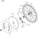
- FIG. 4 is an exploded perspective view showing a configuration for fastening an image board for a rotation wheel according to an embodiment of the present invention to a wheel frame.
- FIG. 5 is a cross-sectional view showing the configuration of the image board for a rotation wheel according to an embodiment of the present invention.
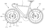
- FIGS. 6 and 7 are side views showing that the image board for a rotation wheel according to an embodiment of the present invention is mounted on various vehicles.
- FIGS. 8 to 10 are exploded perspective views showing that the image board for a rotation wheel according to an embodiment of the present invention is mounted on a wheel frame with both sides open.
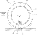
- FIG. 11 is a schematic view illustrating the operation principle of the image board for a rotation wheel according to an embodiment of the present invention.
- FIGS. 12 and 13 are a cross-sectional view and a schematic view illustrating the configurations of various weights according to embodiments of the present invention.
- FIGS. 14 and 15 are cross-sectional view illustrating the configuration of a lead bearing according to an embodiment of the present invention.
- The objects, features, and advantages of the present invention described above will be made clear by the following detailed description. Hereinafter, exemplary embodiments of the present invention are described with reference to the accompanying drawings.
- A
rotation wheel 200 according to an embodiment of the present invention, which is mounted at a lower portion of avehicle 1 for driving thevehicle 1 and is equipped with animage board 100 displaying a still image I regardless of rotation of therotation wheel 200, includes awheel frame 210 and theimage board 100. - The
vehicle 1 can be moved by therotation wheel 200 and therotation wheel 200 has thewheel frame 210 on which theimage board 100 can be mounted. As shown in FIGS. 1, 6, and 7, thevehicle 1 includes a car, bicycle, and a cart, and other vehicles equipped with therotation wheel 200 having thewheel frame 210 such as a motor cycle, a golf cart, a wheelchair, and a baby walker can all be applied to the present invention. - The
wheel frame 210, which is a part to be fitted in atire 212 and rotated by power, is mounted with theimage board 100 that can independently rotate, may be formed in an integrated type such as the wheel frames for cars or golf carts, depending on the type of thevehicle 1, and may be fitted on a rotary shaft (power shaft). Thewheel frame 210, similar to those of a bicycle, a motor cycle, a wheelchair, and a cart, may include arim 214 that is fitted in atire 212, arotational shaft 211 that is disposed at the center of therim 214 and is rotated by torque supplied from a chain, and a plurality ofspokes 215 that connects therotational shaft 211 and therim 214 to each other to support load. - The
image board 100, which is independently rotatably mounted on thewheel frame 210 to display a still image I regardless of rotation of thewheel frame 210, includes: abase plate 110 that is vertically disposed outside or inside thewheel frame 210 to rotate independently from thewheel frame 210 and has a predetermined image I on one side or both sides; and animpeller 120 that is fastened to a lower portion of thebase plate 110 and rotates in the opposite direction to thewheel frame 210 by running wind that flows inside when thevehicle 1 runs. - The image I, which is an image designed in various types such as a logo, an emblem, or an advertising image, may be directly printed on the
base plate 110, or may be implemented by attaching a printed sheet to thebase plate 110 or by drawing an image on a specific image plate and then attaching the image plate to thebase plate 110. - Further, when the
wheel frame 210 is a wheel frame for a car of which a side is exposed and the other side is not exposed, the image I may be disposed on the outer side of thebase plate 110, but when thewheel frame 210 is exposed at both sides such as a wheel for a bicycle, the image I may be disposed on both sides of thebase plate 110, respectively, to increase the effect of exposing the image. - In more detail, as shown in FIGS. 4 and 5, when the
wheel frame 210 is exposed at only one side, the image board may further include: afastening plate 130 that is vertically fastened to the outer side of thewheel frame 210 to rotate along with thewheel frame 210; and abearing assembly 140 that is coupled to the center of thefastening plate 130. - Further, the
base plate 110 may be coupled to thebearing assembly 140 and mounted vertically on the outside of thewheel frame 210 such that it can rotate independently from thewheel frame 210 by thebearing assembly 140. - Further, as shown in FIG. 5, the edge of the
base plate 110 is rounded and curved inward, so thebearing assembly 140 and thefastening plate 130 inside thebase plate 110 are exposed as little as possible. Further, the air that flows over thebase plate 110 when thevehicle 1 runs slides over the bent edge, so movement of thebase plate 110 by the running wind can be reduced. - The
fastening plate 130, which is a plate vertically fastened to a side of thewheel frame 210 and supporting thebase plate 110, is a circular plate that has a plurality offastening holes 133 around the edge for insertingbolts 217 protruding from thewheel body 210 and acenter hole 131 formed at the center to prevent interference with thebearing assembly 140 coupled to thefastening plate 130. Thefastening holes 133 may be formed at a plurality ofwings 132 protruding around thefastening plate 130 to reduce the size of thefastening plate 130. - Accordingly, as shown in FIG. 5, the
fastening plate 130 can be firmly fastened to thewheel frame 210 bynuts 216 that are thread-fastened to the ends of thebolts 217 and press the portions around the fastening holes 113 of thefastening plate 130 vertically mounted on the side of thewheel frame 210 with thebots 217 inserted through the fastening holes 113. - Further, as shown in FIG. 15, when there is a gap between the
fastening plate 130 and thewheel frame 210,coupling tubes 213 that are fitted on thebolts 217 between thefastening plate 130 and thewheel frame 210 to support a side of thefastening plate 130 may be provided. - A
fixing shaft 150, which is a part fitted in the center of thebearing assembly 140, disposed between thebearing assembly 140 and thebase plate 110, and rotatably coupled to thefastening plate 130 by the bearing assembly, has a first end fitted in thebearing assembly 140 and a second end coupled to the center of thebase plate 110 as shown in FIG. 4. - Fastening
holes 151 for thread-fastening are formed at the second end of thefixing shaft 150, so thefixing shaft 150 can be firmly fastened inside thebase plate 110 by bolts that are tightened in fasteningholes 111 formed through thebase plate 110 at positions corresponding to thefastening holes 151 as shown in FIG. 4. Further, anexpansion plate 152 may be formed to be extended along the circumference at the second end fastened to thebase plate 110 so that the fixing shaft can be stably supported on the inner side of thebase plate 110. - The
bearing assembly 140, which is a part coupled to the center of theefastening plate 130 to physically separate thebase plate 110 from rotation of thewheel frame 210, is fixed around the outer side at the center of thefastening plate 130 and may be fitted on thefixing shaft 150 for fastening thebase plate 110 to thebearing assembly 140. - The
bearing assembly 140 includes a plurality ofbearings image board 100 can be reduced by friction and inertia generated by rotation of thebearings bearing assembly 140 is composed of threebearings base plate 110 by theinnermost bearing 141 and rotation of thewheel frame 210 by theoutermost bearing 143 can be physically separated by thebearing 142 between theinnermost bearing 141 and theoutermost bearing 143, so the torque F1 (see FIG. 11) can be further reduced. - The
impeller 120, which is a part generating opposite torque F2 for offsetting the torque F1 generated by rotation of thewheel frame 210 in order to keep the image I shown without moving on thebase plate 110 even though thewheel frame 210 rotates at a high speed, is fastened to the inner side of thebase plate 110 and is rotated in opposite direction to thewheel frame 210 by running wind flowing inside when thevehicle 1 runs. - An end of a
rotational shaft 122 of theimpeller 120 is fixed to the inner side of thebase plate 110 and a plurality ofblades 121 that is curved or inclined to be rotated in the opposite direction to thewheel frame 210 by the running wind from the front is arranged around therotational shaft 122. Accordingly, as theblades 121 are rotated about therotational shaft 122 by the running wind, the torque F2 is generated. - Further, though not shown in the figures, a bearing (not shown) for supporting rotation of the
blades 121 may be disposed at the joints between therotational shaft 122 and theblades 121. - As described above, since the
impeller 120 that is rotated in the opposite direction to thewheel frame 210 by running wind that flows inside when thevehicle 1 runs is mounted on the lower side of thebase plate 110, the torque F1 generated by thewheel frame 210 rotating when thevehicle 1 runs is offset by inertial force F2 generated by rotation of theimpeller 120 and friction force F2 applied on theblades 121, whereby it is possible to keep the image I fixed regardless of the rotation of thewheel frame 210. The inertia force F2 generated in the opposite direction to the rotational direction of thewheel frame 210 by the rotation of theblades 121 is caused by a gyro phenomenon. - Further, as the
wheel frame 210 rotates at higher speeds, the rotational speed of theimpeller 120 is increased and the generated inertia force and the friction force are increased, it is possible to keep the image I fixed regardless of the rotational speed of thewheel frame 210. - If the
wheel frame 210 hasspokes 215 and is open at both sides, similar to those of a bicycle, a motor cycle, a golf cart, a wheelchair, and a cart, as shown in FIG. 8, the inner side of bearingassembly 140 is fitted on therotational shaft 211 of thewheel frame 210 and a fastening hole formed at the center of thebase plate 110 is fitted on the outside of the bearingassembly 140, whereby the image board can be vertically mounted on the outer side of thewheel frame 210 such that it can independently rotate. - In this configuration, as in the type of fastening an image board to the
wheel frame 210 for a car, a specific fastening plate (not shown) may be provided to more strongly fit the bearingassembly 140 on therotational shaft 211 or more strongly fit the bearingassembly 140 in thebase plate 110. - Further, as shown in FIG. 9, the
base plate 110 may be vertically fitted inside thewheel frame 210, whereby theimage board 100 can be protected from the outside by the spoke without being exposed to the outside and the external appearance can be improved. - To this end, the bearing
assembly 140 may be laterally fitted on the horizontalrotational shaft 211 of thewheel frame 210 by the hole therein and thebase plate 110 may be fitted on the bearingassembly 140 and vertically fitted inside thewheel frame 210 such that it can be rotated independently from thewheel frame 210 by the bearingassembly 140. - On the other hand, since the
impeller 120 is mounted on thebase plate 110, theimage board 100 according to an embodiment of the present invention may further includes a compensatingweight 170 for preventing the total weight of thebase plate 110 concentrates on the portion where theimpeller 120 is mounted. - The compensating
weight 170, as shown in FIGS. 12 and 13, is disposed around the circumferential edge of thebase plate 110 at a predetermined distance from the end of the fixingshaft 150 and has weight corresponding to (the same as or almost close to) the weight of theimpeller 120, so it compensates for eccentricity of the total weight of thebase plate 110 due to theimpeller 120 mounted on thebase plate 110. - Further, the
image board 100 according to an embodiment of the present invention further includesweights 160 that applies load downward so that the image I on thebase plate 110 can be maintained in place when thevehicle 1 is stopped. - As shown in FIG. 13, three
weights 160 may be disposed around the circumferential edge of thebase plate 110 with regular intervals on the inner side of thebase plate 110 at predetermined distances from the end of the fixingshaft 150. - Accordingly, when one of the
weights 160 is positioned at an upper portion and the twoweights 160 are positioned at a lower portion while thebase plate 110 is rotated by external force, as shown in the figure, the load applied downward is increased by the difference between the load of the twoweights 160 at the lower portion and the load of theweight 160 at the upper portion. Therefore, thebase plate 110 is maintained in the position with the twoweights 160 at the lower portion in parallel by the load difference of theweights 160. - The
impeller 120 may be rotatably disposed at a lower portion on the inner side of thebase plate 110, between two of the threeweights 160. - Since the three
weights 160 are arranged with regular intervals around the circumferential edge of thebase plate 110 at predetermined distances from the end of the fixingshaft 150, eccentricity of the total weight of thebase plate 110 is prevented by theweights 160. Accordingly, even if theweights 160 are rotated along with thebase plate 110 due to malfunction of the bearingassembly 140, it is possible to preclude the problem that vibration is generated or steering function is adversely influenced by eccentricity of theweights 160, thereby causing a safety accident. - On the other hand, since the bearing
assembly 140 is composed of the plurality of thebearings base plate 110 may be spaced by the gaps among the balls between the inner races and the outer races of thebearings shaft 150 may be inclined by the weight of thebase plate 110 fastened to the end of the fixingshaft 150, so thebase plate 110 that has been vertically disposed may be inclined. - Accordingly, in order to prevent such a phenomena, the bearing
assembly 140 according to the embodiment of the present invention, as shown in Fig. 15, may further include a lead bearing 144 that is disposed on the rear end of theinnermost bearing 141 and supports the end of the fixingshaft 150 fitted in the inner race of theinnermost bearing 141 - The
lead bearing 144 may be thread-fastened to theinnermost bearing 141 to be firmly fixed to theinnermost bearing 141. Therefore, the end of the fixingshaft 150 is supported with the end inserted in the inner races of theinnermost bearing 141 and the lead bearing 144, so it is possible to minimize the inclination of thebase plate 110 due to its own weight. - It will be apparent to those skilled in the art that the foregoing present invention is not limited by the foregoing embodiments and the accompanying drawings, and various modifications and changes may be made without departing from the scope and spirit of the invention
Claims (4)
- An image board for a rotation wheel that is mounted on a rotation wheel (200) of a vehicle (1) and displays a still image (I) regardless of rotation of the rotation wheel (200), the image board comprising:a base plate (110) that is vertically disposed outside or inside a wheel frame (210) mounted on the rotation wheel (200) to rotate independently from the wheel frame (210) and has a predetermined image (I) on one side or both sides; andan impeller (120) that is fastened to a lower portion of the base plate (110) and rotates in the opposite direction to the rotation wheel (200) by running wind that flows inside when the vehicle (1) runs;
- The image board of claim 1, further comprising:a fastening plate (130) that is vertically fastened to an outer side of the wheel frame (210) and rotates along with the wheel frame (210); anda bearing assembly (140) that is fitted in the center of the fastening plate (130),wherein the base plate (110) is fitted on the bearing (140) and vertically mounted on the outer side of the wheel frame (210) to be rotated independently from the wheel frame (210) by the bearing assembly (140).
- The image board of claim 1, further comprising a bearing assembly (140) that is laterally inserted and fitted on a horizontal rotational shaft (211) of the wheel frame (210) by a inserting hole therein,
wherein and the base plate (140) is fitted on the outer circumference of the bearing assembly (140) and vertically fitted inside the wheel frame (210) to be rotated independently from the wheel frame (210) by the bearing assembly (140). - A rotation wheel that is mounted at a lower portion of a vehicle (1), rotates to drive the vehicle (1), and displays a still image (I), the rotation wheel comprising:a wheel frame (210) that is fitted in a tire (212) and rotated by power; andan image board (100) including: a base plate (110) that is vertically disposed outside or inside a wheel frame (210) to rotate independently from the wheel frame (210) and has a predetermined image (I) on one side or both sides; and an impeller (120) that is fastened to a lower portion of the base plate (110) and rotates in the opposite direction to the wheel frame (210) by running wind that flows inside when the vehicle (1) runs.
Applications Claiming Priority (2)
| Application Number | Priority Date | Filing Date | Title |
|---|---|---|---|
| KR1020130149708A KR101540103B1 (en) | 2013-12-04 | 2013-12-04 | Wheel Cover Apparatus For Automobile |
| PCT/KR2014/011855 WO2015084084A1 (en) | 2013-12-04 | 2014-12-04 | Image board for rotation wheel and rotation wheel including same |
Publications (2)
| Publication Number | Publication Date |
|---|---|
| EP3090884A1 true EP3090884A1 (en) | 2016-11-09 |
| EP3090884A4 EP3090884A4 (en) | 2017-08-16 |
Family
ID=53273762
Family Applications (1)
| Application Number | Title | Priority Date | Filing Date |
|---|---|---|---|
| EP14867813.9A Withdrawn EP3090884A4 (en) | 2013-12-04 | 2014-12-04 | Image board for rotation wheel and rotation wheel including same |
Country Status (5)
| Country | Link |
|---|---|
| EP (1) | EP3090884A4 (en) |
| JP (1) | JP6431927B2 (en) |
| KR (1) | KR101540103B1 (en) |
| CN (1) | CN105916701B (en) |
| WO (1) | WO2015084084A1 (en) |
Families Citing this family (1)
| Publication number | Priority date | Publication date | Assignee | Title |
|---|---|---|---|---|
| KR101768044B1 (en) * | 2014-04-14 | 2017-08-30 | 유충섭 | Image Board For Rotation Wheel And, Rotation Wheel Including The Same |
Family Cites Families (20)
| Publication number | Priority date | Publication date | Assignee | Title |
|---|---|---|---|---|
| CN2093769U (en) * | 1991-05-27 | 1992-01-22 | 韦云展 | Fixed cover disc for rotating wheel |
| GB2337233A (en) * | 1998-05-07 | 1999-11-17 | Daniel John Butler | Vehicle wheel cover |
| JP3126124B1 (en) * | 1999-12-03 | 2001-01-22 | 株式会社シンセイ | Stationary plate device and rotating body device with stationary plate |
| JP2001354001A (en) * | 2000-06-12 | 2001-12-25 | Shoei Shoji Kk | Indicator mounted on car wheel |
| KR20020047469A (en) * | 2000-12-13 | 2002-06-22 | 류정열 | Inner structure of wheel for automobiles |
| NL1018623C1 (en) * | 2001-07-24 | 2002-08-27 | Paul Johan Willem Mari Nooijen | Adjustable counterweight for stationary hubcap. |
| JP2004161025A (en) * | 2002-11-08 | 2004-06-10 | Kokurin Ko | Rotary light emitting device and wheel using this device |
| GB0300553D0 (en) * | 2003-01-10 | 2003-02-12 | Bentley Motors Ltd | Apparatus for maintaining the orientation of a badge or other insignia |
| KR20040107907A (en) * | 2003-06-14 | 2004-12-23 | 배운호 | a tire wheel for bill board of battle neither have not |
| US20050062336A1 (en) * | 2003-09-18 | 2005-03-24 | Leslie Hsiao | Non-rotating display wheel cover |
| JP2005178493A (en) * | 2003-12-18 | 2005-07-07 | Ntn Corp | Wheel cap |
| US7226132B2 (en) * | 2004-09-09 | 2007-06-05 | Media Planett | Revolving ornamentation for wheel |
| US20060087171A1 (en) * | 2004-10-21 | 2006-04-27 | Dwayne Riley | Spinning rims for a bicycle |
| US7347504B1 (en) * | 2005-06-29 | 2008-03-25 | Grand General Accessories Manufacturing Inc. | Decorative self propelling spinner attached like a hubcap to the wheel of a vehicle |
| CN101049792A (en) * | 2006-04-07 | 2007-10-10 | 何世权 | Embedded type directional mark for wheel hub of automobile |
| KR20090004092U (en) * | 2007-10-29 | 2009-05-06 | 이일섭 | Rotary advertising device attached to the wheel of the vehicle |
| CN201109343Y (en) * | 2007-11-14 | 2008-09-03 | 纪行财 | Marker |
| KR101167826B1 (en) * | 2009-07-08 | 2012-07-26 | 류충섭 | wheel-cover structure for automobile |
| US20130076106A1 (en) * | 2011-09-24 | 2013-03-28 | Thomas J. Mooney | Non-rotating wheel cover assembly with universal lug mounting bracket |
| KR101380303B1 (en) * | 2011-11-01 | 2014-04-01 | 이주원 | Wheel cover of vehicles |
-
2013
- 2013-12-04 KR KR1020130149708A patent/KR101540103B1/en not_active Expired - Fee Related
-
2014
- 2014-12-04 JP JP2016557859A patent/JP6431927B2/en not_active Expired - Fee Related
- 2014-12-04 CN CN201480066763.4A patent/CN105916701B/en not_active Expired - Fee Related
- 2014-12-04 WO PCT/KR2014/011855 patent/WO2015084084A1/en not_active Ceased
- 2014-12-04 EP EP14867813.9A patent/EP3090884A4/en not_active Withdrawn
Also Published As
| Publication number | Publication date |
|---|---|
| WO2015084084A1 (en) | 2015-06-11 |
| KR101540103B1 (en) | 2015-07-30 |
| JP2017502878A (en) | 2017-01-26 |
| CN105916701A (en) | 2016-08-31 |
| EP3090884A4 (en) | 2017-08-16 |
| JP6431927B2 (en) | 2018-11-28 |
| CN105916701B (en) | 2018-04-27 |
| KR20150064866A (en) | 2015-06-12 |
Similar Documents
| Publication | Publication Date | Title |
|---|---|---|
| CN1808857B (en) | in-wheel motor | |
| CN108136890B (en) | In-wheel motor drive device, and connection structure of in-wheel motor drive device and suspension device | |
| US8919478B2 (en) | Bicycle drive unit | |
| US20080093133A1 (en) | Mounting Structure Of Part | |
| JP3737971B2 (en) | Non-rotating indicator attached to a rotating body | |
| US20240383325A1 (en) | Electric vehicle and electric motorcycle | |
| EP3090884A1 (en) | Image board for rotation wheel and rotation wheel including same | |
| CN210618365U (en) | Middle-arranged motor fixing device and frame system of electric bicycle | |
| JP4730078B2 (en) | In-wheel motor | |
| KR101768044B1 (en) | Image Board For Rotation Wheel And, Rotation Wheel Including The Same | |
| US20120286560A1 (en) | Wheel cover for a vehicle | |
| KR100989188B1 (en) | Car wheel caps with balancing | |
| JP2017514753A5 (en) | ||
| JP2017502878A5 (en) | ||
| JP2005199894A (en) | Power unit for electric vehicles | |
| JP5736069B2 (en) | In-wheel motor drive device | |
| KR200307559Y1 (en) | nonrotating billboard of rotation body | |
| KR100594631B1 (en) | Non-rotating emblem indicator attached to vehicle wheel cap | |
| KR200311926Y1 (en) | a tire wheel for bill board of battle neither have not | |
| KR100729040B1 (en) | Automotive hub assembly device | |
| KR20040107907A (en) | a tire wheel for bill board of battle neither have not | |
| CN215399108U (en) | Balance car | |
| KR200357764Y1 (en) | Irrotational wheel cover for vehicles having advertizing face | |
| KR20040102662A (en) | a tire wheel for bill board of battle neither have not | |
| WO2015160111A1 (en) | Image board for rotary wheel and rotary wheel comprising same |
Legal Events
| Date | Code | Title | Description |
|---|---|---|---|
| PUAI | Public reference made under article 153(3) epc to a published international application that has entered the european phase |
Free format text: ORIGINAL CODE: 0009012 |
|
| 17P | Request for examination filed |
Effective date: 20160704 |
|
| AK | Designated contracting states |
Kind code of ref document: A1 Designated state(s): AL AT BE BG CH CY CZ DE DK EE ES FI FR GB GR HR HU IE IS IT LI LT LU LV MC MK MT NL NO PL PT RO RS SE SI SK SM TR |
|
| AX | Request for extension of the european patent |
Extension state: BA ME |
|
| DAX | Request for extension of the european patent (deleted) | ||
| A4 | Supplementary search report drawn up and despatched |
Effective date: 20170719 |
|
| RIC1 | Information provided on ipc code assigned before grant |
Ipc: B60B 7/06 20060101ALI20170713BHEP Ipc: B60B 7/20 20060101ALI20170713BHEP Ipc: B60B 7/00 20060101ALI20170713BHEP Ipc: B60B 7/01 20060101AFI20170713BHEP Ipc: B60B 7/04 20060101ALI20170713BHEP |
|
| RAP1 | Party data changed (applicant data changed or rights of an application transferred) |
Owner name: MIRYOON W&T CORPORATION |
|
| RIN1 | Information on inventor provided before grant (corrected) |
Inventor name: KIM, SUNG HUN Inventor name: YOO, CHUNG SUP Inventor name: KIM, YOON HWA |
|
| GRAP | Despatch of communication of intention to grant a patent |
Free format text: ORIGINAL CODE: EPIDOSNIGR1 |
|
| INTG | Intention to grant announced |
Effective date: 20200401 |
|
| STAA | Information on the status of an ep patent application or granted ep patent |
Free format text: STATUS: THE APPLICATION IS DEEMED TO BE WITHDRAWN |
|
| 18D | Application deemed to be withdrawn |
Effective date: 20200701 |