EP3090856A1 - Forming machine for forming a hollow body, in particular a casing of a solid propellant engine, and deposit head for such a forming machine - Google Patents
Forming machine for forming a hollow body, in particular a casing of a solid propellant engine, and deposit head for such a forming machine Download PDFInfo
- Publication number
- EP3090856A1 EP3090856A1 EP16168638.1A EP16168638A EP3090856A1 EP 3090856 A1 EP3090856 A1 EP 3090856A1 EP 16168638 A EP16168638 A EP 16168638A EP 3090856 A1 EP3090856 A1 EP 3090856A1
- Authority
- EP
- European Patent Office
- Prior art keywords
- adhesive material
- forming
- head
- roller
- belt
- Prior art date
- Legal status (The legal status is an assumption and is not a legal conclusion. Google has not performed a legal analysis and makes no representation as to the accuracy of the status listed.)
- Granted
Links
Images


Classifications
-
- B—PERFORMING OPERATIONS; TRANSPORTING
- B29—WORKING OF PLASTICS; WORKING OF SUBSTANCES IN A PLASTIC STATE IN GENERAL
- B29C—SHAPING OR JOINING OF PLASTICS; SHAPING OF MATERIAL IN A PLASTIC STATE, NOT OTHERWISE PROVIDED FOR; AFTER-TREATMENT OF THE SHAPED PRODUCTS, e.g. REPAIRING
- B29C70/00—Shaping composites, i.e. plastics material comprising reinforcements, fillers or preformed parts, e.g. inserts
- B29C70/04—Shaping composites, i.e. plastics material comprising reinforcements, fillers or preformed parts, e.g. inserts comprising reinforcements only, e.g. self-reinforcing plastics
- B29C70/28—Shaping operations therefor
- B29C70/30—Shaping by lay-up, i.e. applying fibres, tape or broadsheet on a mould, former or core; Shaping by spray-up, i.e. spraying of fibres on a mould, former or core
- B29C70/38—Automated lay-up, e.g. using robots, laying filaments according to predetermined patterns
- B29C70/386—Automated tape laying [ATL]
- B29C70/388—Tape placement heads, e.g. component parts, details or accessories
-
- B—PERFORMING OPERATIONS; TRANSPORTING
- B29—WORKING OF PLASTICS; WORKING OF SUBSTANCES IN A PLASTIC STATE IN GENERAL
- B29C—SHAPING OR JOINING OF PLASTICS; SHAPING OF MATERIAL IN A PLASTIC STATE, NOT OTHERWISE PROVIDED FOR; AFTER-TREATMENT OF THE SHAPED PRODUCTS, e.g. REPAIRING
- B29C53/00—Shaping by bending, folding, twisting, straightening or flattening; Apparatus therefor
- B29C53/80—Component parts, details or accessories; Auxiliary operations
- B29C53/8008—Component parts, details or accessories; Auxiliary operations specially adapted for winding and joining
- B29C53/8016—Storing, feeding or applying winding materials, e.g. reels, thread guides, tensioners
-
- F—MECHANICAL ENGINEERING; LIGHTING; HEATING; WEAPONS; BLASTING
- F02—COMBUSTION ENGINES; HOT-GAS OR COMBUSTION-PRODUCT ENGINE PLANTS
- F02K—JET-PROPULSION PLANTS
- F02K9/00—Rocket-engine plants, i.e. plants carrying both fuel and oxidant therefor; Control thereof
- F02K9/08—Rocket-engine plants, i.e. plants carrying both fuel and oxidant therefor; Control thereof using solid propellants
- F02K9/32—Constructional parts; Details not otherwise provided for
- F02K9/34—Casings; Combustion chambers; Liners thereof
-
- B—PERFORMING OPERATIONS; TRANSPORTING
- B29—WORKING OF PLASTICS; WORKING OF SUBSTANCES IN A PLASTIC STATE IN GENERAL
- B29C—SHAPING OR JOINING OF PLASTICS; SHAPING OF MATERIAL IN A PLASTIC STATE, NOT OTHERWISE PROVIDED FOR; AFTER-TREATMENT OF THE SHAPED PRODUCTS, e.g. REPAIRING
- B29C53/00—Shaping by bending, folding, twisting, straightening or flattening; Apparatus therefor
- B29C53/56—Winding and joining, e.g. winding spirally
- B29C53/58—Winding and joining, e.g. winding spirally helically
- B29C53/60—Winding and joining, e.g. winding spirally helically using internal forming surfaces, e.g. mandrels
- B29C53/62—Winding and joining, e.g. winding spirally helically using internal forming surfaces, e.g. mandrels rotatable about the winding axis
- B29C53/66—Winding and joining, e.g. winding spirally helically using internal forming surfaces, e.g. mandrels rotatable about the winding axis with axially movable winding feed member, e.g. lathe type winding
-
- F—MECHANICAL ENGINEERING; LIGHTING; HEATING; WEAPONS; BLASTING
- F05—INDEXING SCHEMES RELATING TO ENGINES OR PUMPS IN VARIOUS SUBCLASSES OF CLASSES F01-F04
- F05D—INDEXING SCHEME FOR ASPECTS RELATING TO NON-POSITIVE-DISPLACEMENT MACHINES OR ENGINES, GAS-TURBINES OR JET-PROPULSION PLANTS
- F05D2230/00—Manufacture
- F05D2230/30—Manufacture with deposition of material
- F05D2230/31—Layer deposition
-
- Y—GENERAL TAGGING OF NEW TECHNOLOGICAL DEVELOPMENTS; GENERAL TAGGING OF CROSS-SECTIONAL TECHNOLOGIES SPANNING OVER SEVERAL SECTIONS OF THE IPC; TECHNICAL SUBJECTS COVERED BY FORMER USPC CROSS-REFERENCE ART COLLECTIONS [XRACs] AND DIGESTS
- Y10—TECHNICAL SUBJECTS COVERED BY FORMER USPC
- Y10T—TECHNICAL SUBJECTS COVERED BY FORMER US CLASSIFICATION
- Y10T156/00—Adhesive bonding and miscellaneous chemical manufacture
- Y10T156/17—Surface bonding means and/or assemblymeans with work feeding or handling means
- Y10T156/1788—Work traversing type and/or means applying work to wall or static structure
Definitions
- the present invention relates to a forming machine for forming a hollow body, in particular a casing of a solid propellant engine.
- the present invention relates to a forming machine that finds application in plants for manufacturing engine bodies using filament winding technology.
- this technology contemplates using a removable forming drum, winding a plurality of circumferential reinforcing filiform elements on the drum, covering the filiform elements by winding an adhesive coating tape thereon and pressing the adhesive belt against the filiform elements.
- the adhesive belt usually wound on reels, comprises a layer of carbon-fibre-based adhesive material and a protective or releasing strip arranged on only one side of the layer of adhesive material.
- the winding and subsequent pressing are carried out using a deposit head supplied with the above-mentioned adhesive belt and moved by robotized arms.
- the application head is usually constituted by a belt unwinding device and a protective strip removal and recovery device.
- the protective strip is separated from the layer of adhesive material before the adhesive material is pressed against the forming drum and the reinforcing filiform elements.
- pressing is performed using a pressing roller that acts directly on the layer of adhesive material after the protective strip has been removed, and is rotatable about an axis orthogonal to the feed direction of the adhesive belt.
- mechanized apparatuses of the above-described type are used, they are not entirely satisfactory, not only because they generate positioning errors and cause imprecise movement of the head along complex deposit paths, but above all because they are unable to avoid blistering and delamination on the casing being formed, in particular, as the geometrical/size characteristics of the casing change.
- known mechanized apparatuses are not able to prevent contamination of the deposited adhesive material and to ensure uniform and homogeneous distribution of the adhesive material.
- the adhesive material is exposed to external contaminants on one hand, and lack of guidance on the other.
- known mechanized apparatuses do not allow producing a uniform and homogeneous coating independently of the geometrical characteristics of the casing and, in particular, in the presence of protrusions or ribbing transversal to the belt's feed direction.
- the pressing roller since it rotates about an axis orthogonal to the feed direction of the belt, the pressing roller is not able to compact the material in areas close to steps, with which it inevitably interferes and close to which blisters form or flaking takes place.
- the object of the present invention is to provide a forming machine for forming a hollow body, in particular a casing of a solid propellant engine, which enables the above-mentioned problems to be solved in a simple and inexpensive manner.
- a forming machine for forming a hollow body, in particular a casing of a solid propellant engine, as claimed in claim 14.
- the present invention also relates to a deposit head for a forming machine for forming a hollow body.
- a deposit head for a forming machine for forming a hollow body; the deposit head comprising a support frame adapted to be coupled to a moving member, motorized supply means and guide means carried by said support frame to feed, along a predefined feeding path, a belt comprising a layer of adhesive material and a protective strip arranged on only one side of said layer of adhesive material, motorized winding means for winding said protective strip and carried by said frame, and a first pressing roller for pushing said strip and said layer of adhesive material toward a deposit surface of said adhesive material and rotatable about an axis thereof that is orthogonal to said feeding path, characterized by further comprising a second pressing roller for pushing said strip and said adhesive material toward said deposit surface; said second pressing roller being carried by said support frame and being rotatable about an axis thereof forming, with said feeding path, an angle other than 90°; first actuation and guide means being interposed between said support frame and said second pressing roller for moving the second pressing roller in opposite directions along a direction trans
- reference numeral 1 indicates, as a whole, a machine for making a hollow body in general, and for making a (schematically shown) monolithic casing 2 in a composite material for a solid propellant engine (not shown) in particular, to which the following description shall make explicit reference, but without any loss of generality.
- the machine 1 which is integrated in a forming plant, not visible in the accompanying drawings, comprises a removable forming drum 3 of known type, which is coupled to its own support structure 4 and is motorized to rotate about its horizontal axis 7.
- the structure has a base 5 fastened to a floor 6.
- the machine 1 also comprises a known winding unit, not shown, for winding a plurality of reinforcing filiform elements, not visible in the accompanying drawings, on the drum 3, and a robotized unit 10 for creating a layer 11 of elongated filiform elements spread over the drum 3.
- the winding unit and the robotized unit 10 are expediently arranged on opposite sides of the drum 3.
- the robotized unit 10 comprises a deposit head 13 to form layer 11 and an anthropomorphic robot 14, opportunely with six controlled axes.
- the robot 14 comprises a base 15 fastened to the floor 6 next to base 5 in predefined and settable positions, for example by means of reference pins.
- the robot 14 also comprises a motorized articulated arm 16 protruding upwards from the base 15 in a position facing the structure 4 and an outer lateral surface 3A of the drum 3.
- the articulated arm 16 has a lower end portion 18 coupled to the base 15 to translate in opposite directions along a direction 19 parallel to the axis 7 of the drum 3, and a free upper portion 20 coupled to the head 13 in a rotatable manner about an axis 21.
- the deposit head 13 comprises an elongated, boxed support frame 23, which has an intermediate portion 24 connected to portion 20 of the articulated arm 16 and two longitudinally opposite ends, indicated by reference numerals 25 and 26.
- Portion 25 supports an unwinding device 27 for unwinding a reel 28 of belt constituted by a layer 30 of adhesive material to deposit on the drum 3 and a protective strip 31 ( Figure 3 ), preferably Teflon-coated paper, designed to be removed from layer 30, as shall be explained hereinafter.
- Device 27 comprises a motorized unwinding shaft 33, which can rotate about its axis 33A and on which the reel 28 is fitted.
- Portion 26 instead, supports a motorized shaft 34, which can rotate about an axis 34A parallel to axis 33A and constitutes part of a winding device 35 for winding only the protective strip 31 on a reel 36 and drawing the belt 29 unwound from reel 28.
- the winding device 35 tensions and draws the belt 29 along a path P feeding or supplying the belt 29 through a cutting station 37 and a transfer station 38 for transferring the layer 30 of adhesive material onto the drum 3 to cover the elongated reinforcing elements.
- the belt 29 is guided between the cutting station 37 and the transfer station 38 by a pair of idle rollers 39.
- Each of the rollers 39 rolls in contact with the protective strip 31 without ever interacting with the layer 30 of adhesive material.
- Each roller comprises a pair of circumferential ribs 40, which protrude radially from the outer surface of the respective roller 39 and are axially spaced apart from each other by an amount approximating by excess to the width of the belt 29, so as to define axial stops for the sides of belt 29 when the strip 31 is arranged in contact with the surface of the respective roller 38.
- the strip 31 is guided between the transfer station 38 and the rewinding device 35, by idle rollers 41 constructively similar to rollers 39.
- the cutting station 37 is arranged at the outlet from the unwinding device 27 and houses a cutting device 43, in itself known and, opportunely, of the ultrasonic type.
- the cutting device is arranged in a position facing the layer 30 of adhesive material and is controlled to cut only the layer 30 of adhesive material transversely and not to interfere with the protective strip 31.
- a pressing unit 43 is arranged for pushing the layer 30 of adhesive material towards the drum 3 and against the reinforcing filiform elements.
- the transfer station 38 is arranged substantially on the opposite side of the intermediate portion 24 with respect to the upper portion 20 of the articulated arm 16.
- the pressing unit 43 comprises an idle pressing roller 45 for axial compaction.
- the pressing roller 45 comprises a hub covered in an elastomeric material and coupled to a fork 46 through the interposition of elastic elements 46A, for example compression springs.
- the roller 45 rotates about its axis 47 orthogonal to the path P and, in use, is in contact with the strip 31.
- the fork 46 is firmly connected to a slide 48 of a sliding guide device 49, of known type and not described in detail, the guide 50 of which is firmly connected to the intermediate portion 24 of the frame 23.
- the slide 48 is movable in opposite directions towards and away from the strip 31 under the force of an actuator 51, preferably pneumatic and controlled by proportional valve means, in a direction 52 orthogonal to the path P, parallel to axis 21 and orthogonal to axes 33A and 34A.
- the fork 46 is instead locked in an angularly fixed position about direction 52 with respect to the frame 23.
- unit 43 also comprises a further pressing roller 54 for circumferential pressing and compaction of the adhesive material 30 on the drum 3 and against the reinforcing filiform elements.
- Roller 54 which is arranged downstream of roller 45 in the feed direction of the belt 29, namely between roller 45 and rollers 41, in use, acts like roller 45 against the strip 31 and is implemented in the same way as roller 45.
- Roller 54 is idly coupled to an associated fork 56, always through the interposition of elastically yielding elements 54A, to rotate about its axis 55.
- the fork 56 is coupled to the frame 23 through the interposition of an actuating unit 57, in turn comprising a movable structure 58 coupled to the frame 23 through the interposition of a hinge 59.
- the hinge has a hinge axis 60 parallel to direction 52 and to axis 21.
- a motorized actuating unit 61 is provided between the structure 58 and the frame 23 to rotate the structure 58 with respect to the frame 23 and roller 45 in opposite directions about axis 60.
- Unit 61 is opportunely of the belt type.
- the actuating unit 57 also comprises a motorized sliding guide assembly 64, which comprises a rectilinear guide 65 that is firmly connected to the structure 58 and extends in a direction 65A, orthogonal to axis 60 and direction 52 and transversal to the path P.
- Assembly 64 comprises a motorized slide 66, which is coupled to the guide 65 and is movable in opposite directions along the guide 65 under the action of an actuator unit 67, preferably of the belt type.
- unit 43 comprises a further sliding guide assembly 68 constructively similar to assembly 49 for moving fork 56 in opposite directions towards and away from the strip 31 in a direction 70 parallel to direction 52 and axis 60.
- assembly 68 comprises a rectilinear guide 71 parallel to direction 70 and integrally connected to slide 66 and a motorized slide 72 coupled to guide 71 and carrying the integrally connected fork 56.
- a synchronization and control unit 75 sets the drum 3 in rotation about its axis 7 and controls the robot 14, which first positions the head 13 with respect to the drum 3 and then moves the head 13, following a predetermined motion profile such as to allow the desired covering of the filiform elements deposited on the drum 3. Simultaneously with the advancement of the head 13, devices 27 and 35 are activated and the belt 29 advances along the path P.
- roller 45 positioned in its advanced pressing position, forces the layer 30 of adhesive material against the drum 3, making it adhere to the underlying filiform elements.
- the belt 29 advances in station 38, moving in unison with the drum 3, without interacting with roller 54, which is kept in its retracted position until the first idle roller 41 is reached, beyond which, or rather at the outlet from the station 38, the change in direction of the path P causes the progressive detachment of the strip 31 from the layer of adhesive material, which remains on the drum 3 while the strip 31 is drawn forwards by the rewinding device 35 and always guided by rollers 41.
- roller 54 during the initial and final phases of transfer, where there is a leading portion 77 and a trailing portion 78, respectively, of the adhesive material delimited by two consecutive transverse cuts T1 and T2 of only the adhesive material by means of device 43, roller 54, until now kept in a retracted rest position, shown in Figure 3 , is advanced towards the drum 3 and brought to the pressing position. After this, roller 54 is translated in direction 65, pressing parts 77 and 78.
- roller 54 prior to its advancement, roller 54 is oriented by rotating the movable structure 58 about axis 60 such that the axis 55 of rotation forms a right angle to the cuts T1 and T2. In this way, all areas of portions 77 and 78 are pressed against the drum 3, ensuring perfect adhesion of the areas of end portions 77 and 78, including the areas at the extremities delimited by cuts T1 and T2.
- the constant connection between the layer 30 of adhesive material and the strip 31 and the constant tensioning of the belt enable always guiding the adhesive material 30 along a predefined and unvarying path P and always arranging the adhesive material 30 along a predefined coating trajectory.
- the adhesive material is always distributed uniformly on the reinforcing filiform elements without occurrences of build-up or lack of adhesive material.
- the lack of direct contact between the pressing rollers 45 and 54 and the adhesive material allows having pressing rollers that are always clean and achieving uniform distribution of the adhesive material.
- the constant coupling between the adhesive material and the strip and the presence of pressing roller 54 enable performing the transfer even when using adhesive materials with low adhesiveness, without this causing difficulties in adhesion of the leading portions 77 of the layer of adhesive material to the drum 3.
Landscapes
- Engineering & Computer Science (AREA)
- Mechanical Engineering (AREA)
- Chemical & Material Sciences (AREA)
- Robotics (AREA)
- Composite Materials (AREA)
- Combustion & Propulsion (AREA)
- General Engineering & Computer Science (AREA)
- Folding Of Thin Sheet-Like Materials, Special Discharging Devices, And Others (AREA)
- Adhesive Tape Dispensing Devices (AREA)
- Tyre Moulding (AREA)
- Chemical Kinetics & Catalysis (AREA)
- Materials Engineering (AREA)
- Metallurgy (AREA)
- Organic Chemistry (AREA)
- Motor Or Generator Frames (AREA)
- Adhesives Or Adhesive Processes (AREA)
Abstract
Description
- The present invention relates to a forming machine for forming a hollow body, in particular a casing of a solid propellant engine.
- In particular, the present invention relates to a forming machine that finds application in plants for manufacturing engine bodies using filament winding technology.
- As is known, this technology contemplates using a removable forming drum, winding a plurality of circumferential reinforcing filiform elements on the drum, covering the filiform elements by winding an adhesive coating tape thereon and pressing the adhesive belt against the filiform elements.
- The adhesive belt, usually wound on reels, comprises a layer of carbon-fibre-based adhesive material and a protective or releasing strip arranged on only one side of the layer of adhesive material.
- The winding and successive pressing of the adhesive belt, initially performed by hand and, later, using mechanized apparatuses, have been found to be extremely complex and delicate operations. In fact, incorrect or imprecise winding of the adhesive belt or an inadequate or uneven pressing of the adhesive belt cause the formation of blisters, contaminated areas and subsequent delamination and, in general, the formation of structural defects that result in inevitable rejection of the casing.
- In current mechanized apparatuses, the winding and subsequent pressing are carried out using a deposit head supplied with the above-mentioned adhesive belt and moved by robotized arms.
- The application head is usually constituted by a belt unwinding device and a protective strip removal and recovery device.
- In known applications, the protective strip is separated from the layer of adhesive material before the adhesive material is pressed against the forming drum and the reinforcing filiform elements.
- In known heads, pressing is performed using a pressing roller that acts directly on the layer of adhesive material after the protective strip has been removed, and is rotatable about an axis orthogonal to the feed direction of the adhesive belt.
- Although mechanized apparatuses of the above-described type are used, they are not entirely satisfactory, not only because they generate positioning errors and cause imprecise movement of the head along complex deposit paths, but above all because they are unable to avoid blistering and delamination on the casing being formed, in particular, as the geometrical/size characteristics of the casing change.
- Better position control of the deposit head could be achieved by replacing the robotized arms with gantry movement structures, much more rigid and precise. However, these structures do not find practical application in forming plants using filament winding as they are extremely bulky, as well as being complex and expensive.
- In addition, known mechanized apparatuses are not able to prevent contamination of the deposited adhesive material and to ensure uniform and homogeneous distribution of the adhesive material.
- The foregoing is basically ascribable to the particular way the deposit head is implemented, the pressing roller of which soils itself, as it acts directly on the layer of adhesive material, often carrying part of the adhesive material with it, which it later releases when the chemical-physical characteristics of the material have changed.
- Apart from this, during the depositing phase, the adhesive material is exposed to external contaminants on one hand, and lack of guidance on the other.
- The lack of guidance of the adhesive material while being deposited inevitably results in positioning and compaction errors, which are even more pronounced for the leading and trailing portions of the adhesive belt.
- Moreover, known mechanized apparatuses do not allow producing a uniform and homogeneous coating independently of the geometrical characteristics of the casing and, in particular, in the presence of protrusions or ribbing transversal to the belt's feed direction.
- In fact, in these conditions, since it rotates about an axis orthogonal to the feed direction of the belt, the pressing roller is not able to compact the material in areas close to steps, with which it inevitably interferes and close to which blisters form or flaking takes place.
- Lastly, the known solutions often make the application of adhesive materials difficult, as the latter, by their nature, tend to adhere more to the protective strip than to the reinforcing elements. In fact, in such cases, and especially in the phase of joining the belt's leading portion to the forming drum, it is often difficult to detach the adhesive material from the strip and make it adhere to the forming drum.
- The object of the present invention is to provide a forming machine for forming a hollow body, in particular a casing of a solid propellant engine, which enables the above-mentioned problems to be solved in a simple and inexpensive manner.
- According to the present invention, a forming machine is provided for forming a hollow body, in particular a casing of a solid propellant engine, as claimed in
claim 14. - The present invention also relates to a deposit head for a forming machine for forming a hollow body.
- According to the present invention, a deposit head is provided for a forming machine for forming a hollow body; the deposit head comprising a support frame adapted to be coupled to a moving member, motorized supply means and guide means carried by said support frame to feed, along a predefined feeding path, a belt comprising a layer of adhesive material and a protective strip arranged on only one side of said layer of adhesive material, motorized winding means for winding said protective strip and carried by said frame, and a first pressing roller for pushing said strip and said layer of adhesive material toward a deposit surface of said adhesive material and rotatable about an axis thereof that is orthogonal to said feeding path, characterized by further comprising a second pressing roller for pushing said strip and said adhesive material toward said deposit surface; said second pressing roller being carried by said support frame and being rotatable about an axis thereof forming, with said feeding path, an angle other than 90°; first actuation and guide means being interposed between said support frame and said second pressing roller for moving the second pressing roller in opposite directions along a direction transversal to said feeding path.
- The invention will now be described with reference to the accompanying drawings, which illustrate a non-limitative embodiment, in which:
-
Figure 1 shows, in side elevation, a machine for forming a casing of a solid propellant engine and made according to the principles of the present invention; -
Figure 2 is a side view, on a much larger scale, of a detail ofFigure 1 ; -
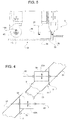
Figure 3 is an enlarged perspective view of a detail ofFigure 2 , with parts removed for clarity; and -
Figures 4 and 5 schematically show two different operating conditions of a detail ofFigure 2 . - In
Figure 1 ,reference numeral 1 indicates, as a whole, a machine for making a hollow body in general, and for making a (schematically shown)monolithic casing 2 in a composite material for a solid propellant engine (not shown) in particular, to which the following description shall make explicit reference, but without any loss of generality. - The
machine 1, which is integrated in a forming plant, not visible in the accompanying drawings, comprises a removable formingdrum 3 of known type, which is coupled to itsown support structure 4 and is motorized to rotate about itshorizontal axis 7. The structure has a base 5 fastened to afloor 6. - The
machine 1 also comprises a known winding unit, not shown, for winding a plurality of reinforcing filiform elements, not visible in the accompanying drawings, on thedrum 3, and arobotized unit 10 for creating alayer 11 of elongated filiform elements spread over thedrum 3. The winding unit and the robotizedunit 10 are expediently arranged on opposite sides of thedrum 3. - Always referring to 1, the
robotized unit 10 comprises adeposit head 13 to formlayer 11 and ananthropomorphic robot 14, opportunely with six controlled axes. Preferably, therobot 14 comprises abase 15 fastened to thefloor 6 next to base 5 in predefined and settable positions, for example by means of reference pins. - The
robot 14 also comprises a motorized articulatedarm 16 protruding upwards from thebase 15 in a position facing thestructure 4 and an outerlateral surface 3A of thedrum 3. - The articulated
arm 16 has alower end portion 18 coupled to thebase 15 to translate in opposite directions along adirection 19 parallel to theaxis 7 of thedrum 3, and a freeupper portion 20 coupled to thehead 13 in a rotatable manner about anaxis 21. - Referring to
Figure 2 , thedeposit head 13 comprises an elongated, boxedsupport frame 23, which has anintermediate portion 24 connected toportion 20 of the articulatedarm 16 and two longitudinally opposite ends, indicated byreference numerals -
Portion 25 supports anunwinding device 27 for unwinding areel 28 of belt constituted by alayer 30 of adhesive material to deposit on thedrum 3 and a protective strip 31 (Figure 3 ), preferably Teflon-coated paper, designed to be removed fromlayer 30, as shall be explained hereinafter. -
Device 27 comprises a motorizedunwinding shaft 33, which can rotate about itsaxis 33A and on which thereel 28 is fitted. -
Portion 26, instead, supports a motorizedshaft 34, which can rotate about anaxis 34A parallel toaxis 33A and constitutes part of awinding device 35 for winding only theprotective strip 31 on areel 36 and drawing thebelt 29 unwound fromreel 28. - Through the
strip 31 wound onreel 36 and by overcoming the predefined counter force exerted by theunwinding device 27, thewinding device 35 tensions and draws thebelt 29 along a path P feeding or supplying thebelt 29 through acutting station 37 and atransfer station 38 for transferring thelayer 30 of adhesive material onto thedrum 3 to cover the elongated reinforcing elements. - The
belt 29 is guided between thecutting station 37 and thetransfer station 38 by a pair ofidle rollers 39. Each of therollers 39 rolls in contact with theprotective strip 31 without ever interacting with thelayer 30 of adhesive material. Each roller comprises a pair ofcircumferential ribs 40, which protrude radially from the outer surface of therespective roller 39 and are axially spaced apart from each other by an amount approximating by excess to the width of thebelt 29, so as to define axial stops for the sides ofbelt 29 when thestrip 31 is arranged in contact with the surface of therespective roller 38. - In the same way, the
strip 31 is guided between thetransfer station 38 and the rewindingdevice 35, byidle rollers 41 constructively similar torollers 39. - The
cutting station 37 is arranged at the outlet from theunwinding device 27 and houses acutting device 43, in itself known and, opportunely, of the ultrasonic type. The cutting device is arranged in a position facing thelayer 30 of adhesive material and is controlled to cut only thelayer 30 of adhesive material transversely and not to interfere with theprotective strip 31. - In the
transfer station 38, instead, apressing unit 43 is arranged for pushing thelayer 30 of adhesive material towards thedrum 3 and against the reinforcing filiform elements. Thetransfer station 38 is arranged substantially on the opposite side of theintermediate portion 24 with respect to theupper portion 20 of the articulatedarm 16. - Referring to
Figure 2 and, in particular, toFigure 3 , thepressing unit 43 comprises an idlepressing roller 45 for axial compaction. Thepressing roller 45 comprises a hub covered in an elastomeric material and coupled to afork 46 through the interposition ofelastic elements 46A, for example compression springs. Theroller 45 rotates about itsaxis 47 orthogonal to the path P and, in use, is in contact with thestrip 31. Thefork 46 is firmly connected to aslide 48 of asliding guide device 49, of known type and not described in detail, theguide 50 of which is firmly connected to theintermediate portion 24 of theframe 23. Theslide 48 is movable in opposite directions towards and away from thestrip 31 under the force of anactuator 51, preferably pneumatic and controlled by proportional valve means, in adirection 52 orthogonal to the path P, parallel toaxis 21 and orthogonal toaxes fork 46 is instead locked in an angularly fixed position aboutdirection 52 with respect to theframe 23. - Still referring to the
Figures 2 and3 ,unit 43 also comprises a furtherpressing roller 54 for circumferential pressing and compaction of theadhesive material 30 on thedrum 3 and against the reinforcing filiform elements. -
Roller 54, which is arranged downstream ofroller 45 in the feed direction of thebelt 29, namely betweenroller 45 androllers 41, in use, acts likeroller 45 against thestrip 31 and is implemented in the same way asroller 45. -
Roller 54 is idly coupled to an associatedfork 56, always through the interposition of elastically yieldingelements 54A, to rotate about itsaxis 55. - The
fork 56 is coupled to theframe 23 through the interposition of an actuatingunit 57, in turn comprising amovable structure 58 coupled to theframe 23 through the interposition of ahinge 59. The hinge has ahinge axis 60 parallel todirection 52 and toaxis 21. Amotorized actuating unit 61 is provided between thestructure 58 and theframe 23 to rotate thestructure 58 with respect to theframe 23 androller 45 in opposite directions aboutaxis 60.Unit 61 is opportunely of the belt type. - Always referring to
Figure 3 , the actuatingunit 57 also comprises a motorized slidingguide assembly 64, which comprises arectilinear guide 65 that is firmly connected to thestructure 58 and extends in adirection 65A, orthogonal toaxis 60 anddirection 52 and transversal to thepath P. Assembly 64 comprises amotorized slide 66, which is coupled to theguide 65 and is movable in opposite directions along theguide 65 under the action of anactuator unit 67, preferably of the belt type. - Between the
slide 66 and thefork 56 ofroller 54,unit 43 comprises a further slidingguide assembly 68 constructively similar toassembly 49 for movingfork 56 in opposite directions towards and away from thestrip 31 in adirection 70 parallel todirection 52 andaxis 60. In particular,assembly 68 comprises arectilinear guide 71 parallel todirection 70 and integrally connected to slide 66 and amotorized slide 72 coupled to guide 71 and carrying the integrally connectedfork 56. - In use, starting from the condition where the filiform elements are wound on the
drum 3, a synchronization and control unit 75 (Fig. 1 ) sets thedrum 3 in rotation about itsaxis 7 and controls therobot 14, which first positions thehead 13 with respect to thedrum 3 and then moves thehead 13, following a predetermined motion profile such as to allow the desired covering of the filiform elements deposited on thedrum 3. Simultaneously with the advancement of thehead 13,devices belt 29 advances along the path P. - When the
belt 29 entersstation 38,roller 45, positioned in its advanced pressing position, forces thelayer 30 of adhesive material against thedrum 3, making it adhere to the underlying filiform elements. At this point, thebelt 29 advances instation 38, moving in unison with thedrum 3, without interacting withroller 54, which is kept in its retracted position until the firstidle roller 41 is reached, beyond which, or rather at the outlet from thestation 38, the change in direction of the path P causes the progressive detachment of thestrip 31 from the layer of adhesive material, which remains on thedrum 3 while thestrip 31 is drawn forwards by the rewindingdevice 35 and always guided byrollers 41. - Referring to
Figure 4 , during the initial and final phases of transfer, where there is a leadingportion 77 and a trailingportion 78, respectively, of the adhesive material delimited by two consecutive transverse cuts T1 and T2 of only the adhesive material by means ofdevice 43,roller 54, until now kept in a retracted rest position, shown inFigure 3 , is advanced towards thedrum 3 and brought to the pressing position. After this,roller 54 is translated indirection 65, pressingparts - Still referring to
Figure 4 , prior to its advancement,roller 54 is oriented by rotating themovable structure 58 aboutaxis 60 such that theaxis 55 of rotation forms a right angle to the cuts T1 and T2. In this way, all areas ofportions drum 3, ensuring perfect adhesion of the areas ofend portions - Referring to
Figure 5 , there is similar uniformity of adhesion of anend portion 79 of the adhesive material arranged next to astep 80 of thedrum 3 that is transversal, orthogonal in this specific case, to the feed path P of thebelt 29. In fact, in this condition, theaxis 55 ofroller 54 is arranged orthogonally to thestep 80 androller 54 completes the pressing of the adhesive material next to thestep 80 during it movement indirection 65A, as shown inFigure 5 . - From the foregoing, it is evident how the constant connection between the
layer 30 of adhesive material and thestrip 31 and the constant tensioning of the belt enable always guiding theadhesive material 30 along a predefined and unvarying path P and always arranging theadhesive material 30 along a predefined coating trajectory. In this way, the adhesive material is always distributed uniformly on the reinforcing filiform elements without occurrences of build-up or lack of adhesive material. - In addition to this, it is evident that the use of two distinct pressing rollers, of which one is orientable, enable uniformly compacting, i.e. with the total absence of bubbles or creases, all of the adhesive material on the reinforcing filiform elements, and therefore also including the leading and trailing portions independently of the direction of the cuts T1 and T2.
- The lack of direct contact between the
pressing rollers - In addition to the foregoing, the constant coupling between the adhesive material and the strip and the presence of pressing
roller 54 enable performing the transfer even when using adhesive materials with low adhesiveness, without this causing difficulties in adhesion of the leadingportions 77 of the layer of adhesive material to thedrum 3. - In addition to this, the lack of contact between pressing rollers and adhesive material avoids, before everything else, the
rollers strip 31.
Claims (16)
- A deposit head for a forming machine for forming hollow bodies; the deposit head comprising a support frame adapted to be coupled to a moving member, motorized supply means and guide means carried by said support frame to feed, along a predefined feeding path, a belt comprising a layer of adhesive material and a protective strip arranged on only one side of said layer of adhesive material, motorized winding means for winding said protective strip and carried by said frame, and a first pressing roller for pushing said strip and said layer of adhesive material toward a deposit surface of said adhesive material and rotatable about an axis thereof that is orthogonal to said feeding path, characterized by further comprising a second pressing roller for pushing said strip and said adhesive material toward said deposit surface; said second pressing roller being carried by said support frame and being rotatable about an axis thereof forming, with said feeding path, an angle other than 90°; first actuation and guide means being interposed between said support frame and said second pressing roller for moving the second pressing roller in opposite directions along a direction transversal to said feeding path.
- A head according to claim 1, characterized in that said transversal direction is a rectilinear direction.
- A head according to claim 1 or 2, characterized in that said second pressing roller is arranged downstream of said first roller in the feeding direction of said belt.
- A head according to one of claims 1 to 3, characterized in that it comprises a hinge interposed between said second pressing roller and said support frame and having a hinge axis orthogonal to said transversal direction and to the rotation axis of said first roller; motorized means being provided for rotating said second roller in opposite directions about said hinge axis.
- A head according to claim 4, characterized in that it comprises motorized actuation means for moving said second pressing roller in opposite directions along a further direction parallel to said hinge axis.
- A head according to claim 5, characterized in that said actuation means are interposed between said second roller and said first actuation and guide means.
- A head according to any one of claims 4 to 6, characterized in that said hinge is interposed between said support frame and said first actuation and guide means.
- A head according to any one of claims 4 to 7, characterized by comprising a movable structure carrying said second pressing roller, said first actuation and guide means, and said actuation means; said hinge being interposed between said frame and said movable structure.
- A head according to any of the preceding claims, characterized in that both said first and second pressing rollers, in use, roll in contact with said protective strip.
- A head according to any of the preceding claims, characterized in that it comprises cutting means for transversally cutting only said layer of adhesive material.
- A head according to claim 10, characterized in that said cutting means are arranged upstream of said first and second pressing rollers in the feeding direction of said belt.
- A head according to any of the preceding claims, characterized in that it comprises means for guiding said belt along said feeding path; said guide means comprising said unwinding means and idle rollers distributed along said path and having radial support surfaces for the longitudinal edges of said belt.
- A robotized unit for a forming machine for forming a hollow body, in particular a casing of a solid propellant engine; the unit comprising a base which can be fixed to the floor and a robotized articulated arm protruding upward from said base, and a deposit head for depositing an adhesive material coupled to a free end of said articulated arm and implemented as claimed in claim 1.
- A forming machine for forming a hollow body, in particular a casing of a solid propellant engine, the machine comprising a forming drum which rotates about an axis thereof, a head for feeding and depositing an adhesive material on said forming drum, and means for moving said head with respect to said drum; the deposit head being implemented as claimed in claim 1.
- A machine according to claim 14, characterized in that both said first and second pressing rollers are arranged, in use, on the opposite side of said strip with respect to said forming drum.
- A machine according to claim 14 or 15, characterized in that said means for moving said head comprise a robotized unit as claimed in claim 13.
Priority Applications (5)
| Application Number | Priority Date | Filing Date | Title |
|---|---|---|---|
| SI201630084T SI3090856T1 (en) | 2015-05-06 | 2016-05-06 | Forming machine for forming a hollow body, in particular a casing of a solid propellant engine, and deposit head for such a forming machine |
| PL16168638T PL3090856T3 (en) | 2015-05-06 | 2016-05-06 | Forming machine for forming a hollow body, in particular a casing of a solid propellant engine, and deposit head for such a forming machine |
| SM20180539T SMT201800539T1 (en) | 2015-05-06 | 2016-05-06 | Forming machine for forming a hollow body, in particular a casing of a solid propellant engine, and deposit head for such a forming machine |
| RS20181150A RS57734B1 (en) | 2015-05-06 | 2016-05-06 | Forming machine for forming a hollow body, in particular a casing of a solid propellant engine, and deposit head for such a forming machine |
| HRP20181579TT HRP20181579T1 (en) | 2015-05-06 | 2018-10-03 | Forming machine for forming a hollow body, in particular a casing of a solid propellant engine, and deposit head for such a forming machine |
Applications Claiming Priority (1)
| Application Number | Priority Date | Filing Date | Title |
|---|---|---|---|
| ITUB2015A000273A ITUB20150273A1 (en) | 2015-05-06 | 2015-05-06 | MACHINE FOR FORMING A HOLLOW BODY, IN PARTICULAR A CASE OF A SOLID PROPELLENT MOTOR, AND STORAGE HEAD FOR SUCH FORMING MACHINE |
Publications (2)
| Publication Number | Publication Date |
|---|---|
| EP3090856A1 true EP3090856A1 (en) | 2016-11-09 |
| EP3090856B1 EP3090856B1 (en) | 2018-07-04 |
Family
ID=53765394
Family Applications (1)
| Application Number | Title | Priority Date | Filing Date |
|---|---|---|---|
| EP16168638.1A Active EP3090856B1 (en) | 2015-05-06 | 2016-05-06 | Forming machine for forming a hollow body, in particular a casing of a solid propellant engine, and deposit head for such a forming machine |
Country Status (14)
| Country | Link |
|---|---|
| US (1) | US10213971B2 (en) |
| EP (1) | EP3090856B1 (en) |
| CY (1) | CY1120750T1 (en) |
| DK (1) | DK3090856T3 (en) |
| ES (1) | ES2689563T3 (en) |
| HR (1) | HRP20181579T1 (en) |
| HU (1) | HUE040123T2 (en) |
| IT (1) | ITUB20150273A1 (en) |
| LT (1) | LT3090856T (en) |
| PL (1) | PL3090856T3 (en) |
| PT (1) | PT3090856T (en) |
| RS (1) | RS57734B1 (en) |
| SI (1) | SI3090856T1 (en) |
| SM (1) | SMT201800539T1 (en) |
Cited By (2)
| Publication number | Priority date | Publication date | Assignee | Title |
|---|---|---|---|---|
| EP3819105A1 (en) * | 2019-11-07 | 2021-05-12 | Tsudakoma Kogyo Kabushiki Kaisha | Automatic lay-up device |
| CN114834067A (en) * | 2022-04-25 | 2022-08-02 | 哈尔滨工业大学 | Yarn guide device for fiber placement |
Families Citing this family (4)
| Publication number | Priority date | Publication date | Assignee | Title |
|---|---|---|---|---|
| FR3008469B1 (en) * | 2013-07-11 | 2015-08-14 | Technip France | GUIDE WHEEL FOR ARMOR WIRE LAYER LAYERS |
| CN106976251B (en) * | 2017-04-18 | 2019-08-13 | 榆林学院 | It is a kind of for composite material prepreg winding or laying shaping mechanism |
| JP7550220B2 (en) * | 2019-10-07 | 2024-09-12 | フィブ・マシニング・システムズ,インコーポレーテッド | W-axis fiber placement head |
| CN114425849B (en) * | 2021-12-31 | 2024-02-23 | 辽宁省优荣节能装备有限公司 | Reverse screwing type steel belt reinforced spiral corrugated pipe processing equipment |
Citations (3)
| Publication number | Priority date | Publication date | Assignee | Title |
|---|---|---|---|---|
| US3775219A (en) * | 1971-04-05 | 1973-11-27 | Goldsworthy Eng Inc | Composite-tape placement head |
| WO2006060270A1 (en) * | 2004-12-02 | 2006-06-08 | The Boeing Company | Device for laying tape materials for aerospace applications |
| EP2230069A2 (en) * | 2009-03-13 | 2010-09-22 | The Boeing Company | Automated placement of vibration damping materials |
Family Cites Families (8)
| Publication number | Priority date | Publication date | Assignee | Title |
|---|---|---|---|---|
| US4569716A (en) * | 1984-03-05 | 1986-02-11 | Cincinnati Milacron Inc. | Strand laying head |
| DE3614365A1 (en) * | 1986-04-28 | 1987-10-29 | Messerschmitt Boelkow Blohm | DEVICE FOR DEPOSITING A PRE-IMPREGNATED RIBBON |
| JPH0688340B2 (en) * | 1988-03-28 | 1994-11-09 | 新日本工機株式会社 | Automatic tape sticking device |
| FR2943943A1 (en) * | 2009-04-02 | 2010-10-08 | Coriolis Composites | METHOD AND MACHINE FOR APPLYING A FIBER BAND TO CONVEXED SURFACES AND / OR WITH AREES |
| JP5422439B2 (en) * | 2010-02-26 | 2014-02-19 | 三菱重工業株式会社 | Prepreg laminating head and prepreg automatic laminating apparatus provided with the same |
| FR2975940A1 (en) * | 2011-05-31 | 2012-12-07 | Forest Line Capdenac | METHOD FOR CONTROLLING THE PLAY BETWEEN BANDS DEPOSITED BY A DRAPING HEAD AND SUB-ASSEMBLY OF A DRAPING HEAD WITH A BOOT CONTROL DEVICE. |
| US8826957B2 (en) * | 2012-08-31 | 2014-09-09 | General Electric Company | Methods and systems for automated ply layup for composites |
| FR3033140B1 (en) * | 2015-02-27 | 2020-12-18 | Airbus Operations Sas | PROCEDURE FOR DEPOSITING A BAND OF MATERIAL AND DEVICE FOR ITS IMPLEMENTATION |
-
2015
- 2015-05-06 IT ITUB2015A000273A patent/ITUB20150273A1/en unknown
-
2016
- 2016-05-06 SI SI201630084T patent/SI3090856T1/en unknown
- 2016-05-06 EP EP16168638.1A patent/EP3090856B1/en active Active
- 2016-05-06 ES ES16168638.1T patent/ES2689563T3/en active Active
- 2016-05-06 US US15/148,575 patent/US10213971B2/en active Active
- 2016-05-06 LT LTEP16168638.1T patent/LT3090856T/en unknown
- 2016-05-06 DK DK16168638.1T patent/DK3090856T3/en active
- 2016-05-06 SM SM20180539T patent/SMT201800539T1/en unknown
- 2016-05-06 PT PT16168638T patent/PT3090856T/en unknown
- 2016-05-06 RS RS20181150A patent/RS57734B1/en unknown
- 2016-05-06 HU HUE16168638A patent/HUE040123T2/en unknown
- 2016-05-06 PL PL16168638T patent/PL3090856T3/en unknown
-
2018
- 2018-10-03 HR HRP20181579TT patent/HRP20181579T1/en unknown
- 2018-10-03 CY CY181101016T patent/CY1120750T1/en unknown
Patent Citations (3)
| Publication number | Priority date | Publication date | Assignee | Title |
|---|---|---|---|---|
| US3775219A (en) * | 1971-04-05 | 1973-11-27 | Goldsworthy Eng Inc | Composite-tape placement head |
| WO2006060270A1 (en) * | 2004-12-02 | 2006-06-08 | The Boeing Company | Device for laying tape materials for aerospace applications |
| EP2230069A2 (en) * | 2009-03-13 | 2010-09-22 | The Boeing Company | Automated placement of vibration damping materials |
Cited By (7)
| Publication number | Priority date | Publication date | Assignee | Title |
|---|---|---|---|---|
| EP3819105A1 (en) * | 2019-11-07 | 2021-05-12 | Tsudakoma Kogyo Kabushiki Kaisha | Automatic lay-up device |
| KR20210055595A (en) * | 2019-11-07 | 2021-05-17 | 츠다코마 고교 가부시키가이샤 | Automatic lay-up device |
| JP2021074925A (en) * | 2019-11-07 | 2021-05-20 | 津田駒工業株式会社 | Automatic laminating apparatus |
| US11458694B2 (en) * | 2019-11-07 | 2022-10-04 | Tsudakoma Kogyo Kabushiki Kaisha | Automatic lay-up device |
| TWI812893B (en) * | 2019-11-07 | 2023-08-21 | 日商津田駒工業股份有限公司 | Automatic stacking device |
| CN114834067A (en) * | 2022-04-25 | 2022-08-02 | 哈尔滨工业大学 | Yarn guide device for fiber placement |
| CN114834067B (en) * | 2022-04-25 | 2024-05-17 | 哈尔滨工业大学 | Yarn guiding device for fiber placement |
Also Published As
| Publication number | Publication date |
|---|---|
| SMT201800539T1 (en) | 2018-11-09 |
| US20170044657A1 (en) | 2017-02-16 |
| EP3090856B1 (en) | 2018-07-04 |
| US10213971B2 (en) | 2019-02-26 |
| ES2689563T3 (en) | 2018-11-14 |
| HRP20181579T1 (en) | 2018-12-14 |
| PT3090856T (en) | 2018-11-02 |
| PL3090856T3 (en) | 2018-12-31 |
| ITUB20150273A1 (en) | 2016-11-06 |
| LT3090856T (en) | 2018-10-25 |
| HUE040123T2 (en) | 2019-02-28 |
| SI3090856T1 (en) | 2018-12-31 |
| CY1120750T1 (en) | 2019-12-11 |
| RS57734B1 (en) | 2018-12-31 |
| DK3090856T3 (en) | 2018-10-22 |
Similar Documents
| Publication | Publication Date | Title |
|---|---|---|
| EP3090856B1 (en) | Forming machine for forming a hollow body, in particular a casing of a solid propellant engine, and deposit head for such a forming machine | |
| EP2106338B1 (en) | Backing film removal system and method using a passive (non powered) take up roller for fiber placement machine | |
| JP5894623B2 (en) | Film processing method and apparatus in packaging machine | |
| US5795432A (en) | Coiling machine with adhesive strip applicator | |
| JPH0362616B2 (en) | ||
| JPH05246589A (en) | Apparatus and method for joining two webs together | |
| US7621479B2 (en) | Supply-roll switching apparatus | |
| JP2019155238A (en) | Coating device and coating method | |
| CN103857612A (en) | Dispenser | |
| KR19990022223A (en) | Tireless adhesive tape winding mandrel and method | |
| US11858768B2 (en) | Method and apparatus for preparing edges of reels of web material | |
| WO2015071839A1 (en) | Apparatus and method for feeding web material for foaming of panels | |
| JP2016117278A (en) | Method and device for attaching portions of backlining material to back of book block | |
| RS60361B1 (en) | Feeding unit for a tissue converting machine for converting a web of two-layer tissue | |
| JPH08259062A (en) | Rewinding device for web material and method for loading it | |
| KR101411343B1 (en) | Apparatus for shifting paper jointing tube | |
| EP3052310A1 (en) | Method for picking up and placing tire components on a transfer drum | |
| JP5258741B2 (en) | Butt splicing device and butt splicing method | |
| CN107922135B (en) | Pick-up mechanism for picking up film material | |
| US20220340315A1 (en) | Wrapping head for wrapping loads, particularly palletized loads, and method of operation thereof | |
| JP6146867B2 (en) | Film processing method and apparatus for raw roll in packaging machine | |
| WO2008017420A1 (en) | Apparatus for applying reinforcement elements to a sail | |
| DE69306752T2 (en) | Device for cutting and applying a connecting strip for a web winding device | |
| JP6114216B2 (en) | Film connection method for raw roll in packaging machine | |
| US20160159079A1 (en) | Method and device for applying adhesive tape to cylindrical bodies |
Legal Events
| Date | Code | Title | Description |
|---|---|---|---|
| PUAI | Public reference made under article 153(3) epc to a published international application that has entered the european phase |
Free format text: ORIGINAL CODE: 0009012 |
|
| AK | Designated contracting states |
Kind code of ref document: A1 Designated state(s): AL AT BE BG CH CY CZ DE DK EE ES FI FR GB GR HR HU IE IS IT LI LT LU LV MC MK MT NL NO PL PT RO RS SE SI SK SM TR |
|
| AX | Request for extension of the european patent |
Extension state: BA ME |
|
| 17P | Request for examination filed |
Effective date: 20161230 |
|
| RBV | Designated contracting states (corrected) |
Designated state(s): AL AT BE BG CH CY CZ DE DK EE ES FI FR GB GR HR HU IE IS IT LI LT LU LV MC MK MT NL NO PL PT RO RS SE SI SK SM TR |
|
| RIC1 | Information provided on ipc code assigned before grant |
Ipc: B29C 70/38 20060101ALN20170808BHEP Ipc: B29C 53/80 20060101AFI20170808BHEP Ipc: B29C 53/66 20060101ALN20170808BHEP |
|
| GRAP | Despatch of communication of intention to grant a patent |
Free format text: ORIGINAL CODE: EPIDOSNIGR1 |
|
| RIC1 | Information provided on ipc code assigned before grant |
Ipc: B29C 53/80 20060101AFI20170926BHEP Ipc: B29C 53/66 20060101ALN20170926BHEP Ipc: B29C 70/38 20060101ALN20170926BHEP |
|
| INTG | Intention to grant announced |
Effective date: 20171010 |
|
| GRAS | Grant fee paid |
Free format text: ORIGINAL CODE: EPIDOSNIGR3 |
|
| RAP1 | Party data changed (applicant data changed or rights of an application transferred) |
Owner name: AVIO S.P.A. |
|
| GRAA | (expected) grant |
Free format text: ORIGINAL CODE: 0009210 |
|
| AK | Designated contracting states |
Kind code of ref document: B1 Designated state(s): AL AT BE BG CH CY CZ DE DK EE ES FI FR GB GR HR HU IE IS IT LI LT LU LV MC MK MT NL NO PL PT RO RS SE SI SK SM TR |
|
| REG | Reference to a national code |
Ref country code: GB Ref legal event code: FG4D |
|
| REG | Reference to a national code |
Ref country code: CH Ref legal event code: EP |
|
| REG | Reference to a national code |
Ref country code: AT Ref legal event code: REF Ref document number: 1014039 Country of ref document: AT Kind code of ref document: T Effective date: 20180715 |
|
| REG | Reference to a national code |
Ref country code: IE Ref legal event code: FG4D |
|
| REG | Reference to a national code |
Ref country code: DE Ref legal event code: R096 Ref document number: 602016003909 Country of ref document: DE |
|
| REG | Reference to a national code |
Ref country code: RO Ref legal event code: EPE |
|
| REG | Reference to a national code |
Ref country code: HR Ref legal event code: TUEP Ref document number: P20181579 Country of ref document: HR |
|
| REG | Reference to a national code |
Ref country code: SE Ref legal event code: TRGR |
|
| REG | Reference to a national code |
Ref country code: NL Ref legal event code: FP |
|
| REG | Reference to a national code |
Ref country code: DK Ref legal event code: T3 Effective date: 20181015 |
|
| REG | Reference to a national code |
Ref country code: PT Ref legal event code: SC4A Ref document number: 3090856 Country of ref document: PT Date of ref document: 20181102 Kind code of ref document: T Free format text: AVAILABILITY OF NATIONAL TRANSLATION Effective date: 20181004 |
|
| REG | Reference to a national code |
Ref country code: NO Ref legal event code: T2 Effective date: 20180704 |
|
| REG | Reference to a national code |
Ref country code: ES Ref legal event code: FG2A Ref document number: 2689563 Country of ref document: ES Kind code of ref document: T3 Effective date: 20181114 |
|
| REG | Reference to a national code |
Ref country code: HR Ref legal event code: T1PR Ref document number: P20181579 Country of ref document: HR |
|
| REG | Reference to a national code |
Ref country code: EE Ref legal event code: FG4A Ref document number: E016231 Country of ref document: EE Effective date: 20181002 |
|
| REG | Reference to a national code |
Ref country code: CH Ref legal event code: NV Representative=s name: BOVARD AG PATENT- UND MARKENANWAELTE, CH |
|
| REG | Reference to a national code |
Ref country code: SK Ref legal event code: T3 Ref document number: E 28576 Country of ref document: SK |
|
| REG | Reference to a national code |
Ref country code: HU Ref legal event code: AG4A Ref document number: E040123 Country of ref document: HU |
|
| REG | Reference to a national code |
Ref country code: GR Ref legal event code: EP Ref document number: 20180402737 Country of ref document: GR Effective date: 20190225 |
|
| REG | Reference to a national code |
Ref country code: DE Ref legal event code: R097 Ref document number: 602016003909 Country of ref document: DE |
|
| PLBE | No opposition filed within time limit |
Free format text: ORIGINAL CODE: 0009261 |
|
| STAA | Information on the status of an ep patent application or granted ep patent |
Free format text: STATUS: NO OPPOSITION FILED WITHIN TIME LIMIT |
|
| REG | Reference to a national code |
Ref country code: HR Ref legal event code: ODRP Ref document number: P20181579 Country of ref document: HR Payment date: 20190506 Year of fee payment: 4 |
|
| 26N | No opposition filed |
Effective date: 20190405 |
|
| PGFP | Annual fee paid to national office [announced via postgrant information from national office to epo] |
Ref country code: MC Payment date: 20190529 Year of fee payment: 4 Ref country code: NO Payment date: 20190509 Year of fee payment: 4 |
|
| PGFP | Annual fee paid to national office [announced via postgrant information from national office to epo] |
Ref country code: RS Payment date: 20190506 Year of fee payment: 4 |
|
| PGFP | Annual fee paid to national office [announced via postgrant information from national office to epo] |
Ref country code: CH Payment date: 20190531 Year of fee payment: 4 Ref country code: IS Payment date: 20190527 Year of fee payment: 4 |
|
| REG | Reference to a national code |
Ref country code: HR Ref legal event code: ODRP Ref document number: P20181579 Country of ref document: HR Payment date: 20200505 Year of fee payment: 5 |
|
| PGFP | Annual fee paid to national office [announced via postgrant information from national office to epo] |
Ref country code: DK Payment date: 20200518 Year of fee payment: 5 Ref country code: FR Payment date: 20200525 Year of fee payment: 5 Ref country code: CY Payment date: 20200505 Year of fee payment: 5 Ref country code: NL Payment date: 20200519 Year of fee payment: 5 Ref country code: ES Payment date: 20200605 Year of fee payment: 5 Ref country code: FI Payment date: 20200504 Year of fee payment: 5 Ref country code: PT Payment date: 20200505 Year of fee payment: 5 Ref country code: DE Payment date: 20200518 Year of fee payment: 5 Ref country code: LU Payment date: 20200520 Year of fee payment: 5 Ref country code: LT Payment date: 20200504 Year of fee payment: 5 Ref country code: GR Payment date: 20200505 Year of fee payment: 5 Ref country code: CZ Payment date: 20200504 Year of fee payment: 5 Ref country code: TR Payment date: 20200505 Year of fee payment: 5 Ref country code: RO Payment date: 20200505 Year of fee payment: 5 Ref country code: IE Payment date: 20200505 Year of fee payment: 5 Ref country code: EE Payment date: 20200504 Year of fee payment: 5 |
|
| PGFP | Annual fee paid to national office [announced via postgrant information from national office to epo] |
Ref country code: SK Payment date: 20200505 Year of fee payment: 5 Ref country code: BE Payment date: 20200525 Year of fee payment: 5 Ref country code: HU Payment date: 20200504 Year of fee payment: 5 Ref country code: LV Payment date: 20200505 Year of fee payment: 5 Ref country code: SI Payment date: 20200504 Year of fee payment: 5 Ref country code: IT Payment date: 20200430 Year of fee payment: 5 Ref country code: BG Payment date: 20200504 Year of fee payment: 5 Ref country code: HR Payment date: 20200505 Year of fee payment: 5 Ref country code: SE Payment date: 20200518 Year of fee payment: 5 Ref country code: GB Payment date: 20200504 Year of fee payment: 5 |
|
| PGFP | Annual fee paid to national office [announced via postgrant information from national office to epo] |
Ref country code: MK Payment date: 20200521 Year of fee payment: 5 |
|
| REG | Reference to a national code |
Ref country code: NO Ref legal event code: MMEP |
|
| PG25 | Lapsed in a contracting state [announced via postgrant information from national office to epo] |
Ref country code: SM Free format text: LAPSE BECAUSE OF NON-PAYMENT OF DUE FEES Effective date: 20201203 Ref country code: NO Free format text: LAPSE BECAUSE OF NON-PAYMENT OF DUE FEES Effective date: 20200531 Ref country code: LI Free format text: LAPSE BECAUSE OF NON-PAYMENT OF DUE FEES Effective date: 20200531 Ref country code: MC Free format text: LAPSE BECAUSE OF NON-PAYMENT OF DUE FEES Effective date: 20200602 Ref country code: CH Free format text: LAPSE BECAUSE OF NON-PAYMENT OF DUE FEES Effective date: 20200531 |
|
| PG25 | Lapsed in a contracting state [announced via postgrant information from national office to epo] |
Ref country code: RS Free format text: LAPSE BECAUSE OF NON-PAYMENT OF DUE FEES Effective date: 20200506 |
|
| PGFP | Annual fee paid to national office [announced via postgrant information from national office to epo] |
Ref country code: PL Payment date: 20201230 Year of fee payment: 5 |
|
| REG | Reference to a national code |
Ref country code: AT Ref legal event code: UEP Ref document number: 1014039 Country of ref document: AT Kind code of ref document: T Effective date: 20180704 |
|
| REG | Reference to a national code |
Ref country code: HR Ref legal event code: PBON Ref document number: P20181579 Country of ref document: HR Effective date: 20210506 |
|
| REG | Reference to a national code |
Ref country code: DE Ref legal event code: R119 Ref document number: 602016003909 Country of ref document: DE |
|
| REG | Reference to a national code |
Ref country code: LT Ref legal event code: MM4D Effective date: 20210506 |
|
| REG | Reference to a national code |
Ref country code: FI Ref legal event code: MAE |
|
| REG | Reference to a national code |
Ref country code: EE Ref legal event code: MM4A Ref document number: E016231 Country of ref document: EE Effective date: 20210531 |
|
| REG | Reference to a national code |
Ref country code: DK Ref legal event code: EBP Effective date: 20210531 |
|
| REG | Reference to a national code |
Ref country code: SE Ref legal event code: EUG |
|
| REG | Reference to a national code |
Ref country code: NL Ref legal event code: MM Effective date: 20210601 |
|
| GBPC | Gb: european patent ceased through non-payment of renewal fee |
Effective date: 20210506 |
|
| REG | Reference to a national code |
Ref country code: SK Ref legal event code: MM4A Ref document number: E 28576 Country of ref document: SK Effective date: 20210506 |
|
| PG25 | Lapsed in a contracting state [announced via postgrant information from national office to epo] |
Ref country code: SE Free format text: LAPSE BECAUSE OF NON-PAYMENT OF DUE FEES Effective date: 20210507 Ref country code: SK Free format text: LAPSE BECAUSE OF NON-PAYMENT OF DUE FEES Effective date: 20210506 Ref country code: CZ Free format text: LAPSE BECAUSE OF NON-PAYMENT OF DUE FEES Effective date: 20210506 Ref country code: CY Free format text: LAPSE BECAUSE OF NON-PAYMENT OF DUE FEES Effective date: 20210506 Ref country code: EE Free format text: LAPSE BECAUSE OF NON-PAYMENT OF DUE FEES Effective date: 20210531 Ref country code: HU Free format text: LAPSE BECAUSE OF NON-PAYMENT OF DUE FEES Effective date: 20210507 Ref country code: HR Free format text: LAPSE BECAUSE OF NON-PAYMENT OF DUE FEES Effective date: 20210506 Ref country code: RO Free format text: LAPSE BECAUSE OF NON-PAYMENT OF DUE FEES Effective date: 20210506 Ref country code: PT Free format text: LAPSE BECAUSE OF NON-PAYMENT OF DUE FEES Effective date: 20211108 Ref country code: FI Free format text: LAPSE BECAUSE OF NON-PAYMENT OF DUE FEES Effective date: 20210506 Ref country code: LU Free format text: LAPSE BECAUSE OF NON-PAYMENT OF DUE FEES Effective date: 20210506 Ref country code: LT Free format text: LAPSE BECAUSE OF NON-PAYMENT OF DUE FEES Effective date: 20210506 Ref country code: BG Free format text: LAPSE BECAUSE OF NON-PAYMENT OF DUE FEES Effective date: 20211130 |
|
| REG | Reference to a national code |
Ref country code: BE Ref legal event code: MM Effective date: 20210531 |
|
| PG25 | Lapsed in a contracting state [announced via postgrant information from national office to epo] |
Ref country code: SI Free format text: LAPSE BECAUSE OF NON-PAYMENT OF DUE FEES Effective date: 20210507 Ref country code: LV Free format text: LAPSE BECAUSE OF NON-PAYMENT OF DUE FEES Effective date: 20210506 Ref country code: GR Free format text: LAPSE BECAUSE OF NON-PAYMENT OF DUE FEES Effective date: 20211207 |
|
| REG | Reference to a national code |
Ref country code: SI Ref legal event code: KO00 Effective date: 20220127 |
|
| PG25 | Lapsed in a contracting state [announced via postgrant information from national office to epo] |
Ref country code: IE Free format text: LAPSE BECAUSE OF NON-PAYMENT OF DUE FEES Effective date: 20210506 Ref country code: GB Free format text: LAPSE BECAUSE OF NON-PAYMENT OF DUE FEES Effective date: 20210506 Ref country code: DK Free format text: LAPSE BECAUSE OF NON-PAYMENT OF DUE FEES Effective date: 20210531 Ref country code: DE Free format text: LAPSE BECAUSE OF NON-PAYMENT OF DUE FEES Effective date: 20211201 |
|
| PG25 | Lapsed in a contracting state [announced via postgrant information from national office to epo] |
Ref country code: NL Free format text: LAPSE BECAUSE OF NON-PAYMENT OF DUE FEES Effective date: 20210601 Ref country code: FR Free format text: LAPSE BECAUSE OF NON-PAYMENT OF DUE FEES Effective date: 20210531 |
|
| PG25 | Lapsed in a contracting state [announced via postgrant information from national office to epo] |
Ref country code: MT Free format text: LAPSE BECAUSE OF NON-PAYMENT OF DUE FEES Effective date: 20200506 |
|
| REG | Reference to a national code |
Ref country code: AT Ref legal event code: MM01 Ref document number: 1014039 Country of ref document: AT Kind code of ref document: T Effective date: 20210506 |
|
| REG | Reference to a national code |
Ref country code: ES Ref legal event code: FD2A Effective date: 20220727 |
|
| PG25 | Lapsed in a contracting state [announced via postgrant information from national office to epo] |
Ref country code: BE Free format text: LAPSE BECAUSE OF NON-PAYMENT OF DUE FEES Effective date: 20210531 |
|
| PG25 | Lapsed in a contracting state [announced via postgrant information from national office to epo] |
Ref country code: AT Free format text: LAPSE BECAUSE OF NON-PAYMENT OF DUE FEES Effective date: 20210506 |
|
| PG25 | Lapsed in a contracting state [announced via postgrant information from national office to epo] |
Ref country code: ES Free format text: LAPSE BECAUSE OF NON-PAYMENT OF DUE FEES Effective date: 20210507 |
|
| PG25 | Lapsed in a contracting state [announced via postgrant information from national office to epo] |
Ref country code: PL Free format text: LAPSE BECAUSE OF NON-PAYMENT OF DUE FEES Effective date: 20210506 |
|
| PG25 | Lapsed in a contracting state [announced via postgrant information from national office to epo] |
Ref country code: IT Free format text: LAPSE BECAUSE OF NON-PAYMENT OF DUE FEES Effective date: 20200506 |
|
| PG25 | Lapsed in a contracting state [announced via postgrant information from national office to epo] |
Ref country code: AL Free format text: LAPSE BECAUSE OF NON-PAYMENT OF DUE FEES Effective date: 20200506 |
|
| PG25 | Lapsed in a contracting state [announced via postgrant information from national office to epo] |
Ref country code: IT Free format text: LAPSE BECAUSE OF NON-PAYMENT OF DUE FEES Effective date: 20210506 |
|
| PG25 | Lapsed in a contracting state [announced via postgrant information from national office to epo] |
Ref country code: IS Free format text: LAPSE BECAUSE OF NON-PAYMENT OF DUE FEES Effective date: 20201202 |