EP3090826A1 - Deposition of braze preform - Google Patents
Deposition of braze preform Download PDFInfo
- Publication number
- EP3090826A1 EP3090826A1 EP16168497.2A EP16168497A EP3090826A1 EP 3090826 A1 EP3090826 A1 EP 3090826A1 EP 16168497 A EP16168497 A EP 16168497A EP 3090826 A1 EP3090826 A1 EP 3090826A1
- Authority
- EP
- European Patent Office
- Prior art keywords
- braze
- components
- braze filler
- void
- component
- Prior art date
- Legal status (The legal status is an assumption and is not a legal conclusion. Google has not performed a legal analysis and makes no representation as to the accuracy of the status listed.)
- Granted
Links
Images

Classifications
-
- B—PERFORMING OPERATIONS; TRANSPORTING
- B23—MACHINE TOOLS; METAL-WORKING NOT OTHERWISE PROVIDED FOR
- B23K—SOLDERING OR UNSOLDERING; WELDING; CLADDING OR PLATING BY SOLDERING OR WELDING; CUTTING BY APPLYING HEAT LOCALLY, e.g. FLAME CUTTING; WORKING BY LASER BEAM
- B23K1/00—Soldering, e.g. brazing, or unsoldering
- B23K1/20—Preliminary treatment of work or areas to be soldered, e.g. in respect of a galvanic coating
-
- B—PERFORMING OPERATIONS; TRANSPORTING
- B23—MACHINE TOOLS; METAL-WORKING NOT OTHERWISE PROVIDED FOR
- B23K—SOLDERING OR UNSOLDERING; WELDING; CLADDING OR PLATING BY SOLDERING OR WELDING; CUTTING BY APPLYING HEAT LOCALLY, e.g. FLAME CUTTING; WORKING BY LASER BEAM
- B23K3/00—Tools, devices or special appurtenances for soldering, e.g. brazing, or unsoldering, not specially adapted for particular methods
- B23K3/06—Solder feeding devices; Solder melting pans
- B23K3/0607—Solder feeding devices
- B23K3/0623—Solder feeding devices for shaped solder piece feeding, e.g. preforms, bumps, balls, pellets, droplets
-
- B—PERFORMING OPERATIONS; TRANSPORTING
- B23—MACHINE TOOLS; METAL-WORKING NOT OTHERWISE PROVIDED FOR
- B23K—SOLDERING OR UNSOLDERING; WELDING; CLADDING OR PLATING BY SOLDERING OR WELDING; CUTTING BY APPLYING HEAT LOCALLY, e.g. FLAME CUTTING; WORKING BY LASER BEAM
- B23K3/00—Tools, devices or special appurtenances for soldering, e.g. brazing, or unsoldering, not specially adapted for particular methods
- B23K3/06—Solder feeding devices; Solder melting pans
- B23K3/0607—Solder feeding devices
- B23K3/0638—Solder feeding devices for viscous material feeding, e.g. solder paste feeding
-
- B—PERFORMING OPERATIONS; TRANSPORTING
- B23—MACHINE TOOLS; METAL-WORKING NOT OTHERWISE PROVIDED FOR
- B23K—SOLDERING OR UNSOLDERING; WELDING; CLADDING OR PLATING BY SOLDERING OR WELDING; CUTTING BY APPLYING HEAT LOCALLY, e.g. FLAME CUTTING; WORKING BY LASER BEAM
- B23K35/00—Rods, electrodes, materials, or media, for use in soldering, welding, or cutting
- B23K35/02—Rods, electrodes, materials, or media, for use in soldering, welding, or cutting characterised by mechanical features, e.g. shape
- B23K35/0222—Rods, electrodes, materials, or media, for use in soldering, welding, or cutting characterised by mechanical features, e.g. shape for use in soldering or brazing
- B23K35/0244—Powders, particles or spheres; Preforms made therefrom
-
- B—PERFORMING OPERATIONS; TRANSPORTING
- B23—MACHINE TOOLS; METAL-WORKING NOT OTHERWISE PROVIDED FOR
- B23K—SOLDERING OR UNSOLDERING; WELDING; CLADDING OR PLATING BY SOLDERING OR WELDING; CUTTING BY APPLYING HEAT LOCALLY, e.g. FLAME CUTTING; WORKING BY LASER BEAM
- B23K35/00—Rods, electrodes, materials, or media, for use in soldering, welding, or cutting
- B23K35/22—Rods, electrodes, materials, or media, for use in soldering, welding, or cutting characterised by the composition or nature of the material
- B23K35/24—Selection of soldering or welding materials proper
- B23K35/30—Selection of soldering or welding materials proper with the principal constituent melting at less than 1550°C
- B23K35/3006—Ag as the principal constituent
-
- B—PERFORMING OPERATIONS; TRANSPORTING
- B23—MACHINE TOOLS; METAL-WORKING NOT OTHERWISE PROVIDED FOR
- B23K—SOLDERING OR UNSOLDERING; WELDING; CLADDING OR PLATING BY SOLDERING OR WELDING; CUTTING BY APPLYING HEAT LOCALLY, e.g. FLAME CUTTING; WORKING BY LASER BEAM
- B23K35/00—Rods, electrodes, materials, or media, for use in soldering, welding, or cutting
- B23K35/22—Rods, electrodes, materials, or media, for use in soldering, welding, or cutting characterised by the composition or nature of the material
- B23K35/24—Selection of soldering or welding materials proper
- B23K35/30—Selection of soldering or welding materials proper with the principal constituent melting at less than 1550°C
- B23K35/3013—Au as the principal constituent
-
- B—PERFORMING OPERATIONS; TRANSPORTING
- B23—MACHINE TOOLS; METAL-WORKING NOT OTHERWISE PROVIDED FOR
- B23K—SOLDERING OR UNSOLDERING; WELDING; CLADDING OR PLATING BY SOLDERING OR WELDING; CUTTING BY APPLYING HEAT LOCALLY, e.g. FLAME CUTTING; WORKING BY LASER BEAM
- B23K35/00—Rods, electrodes, materials, or media, for use in soldering, welding, or cutting
- B23K35/22—Rods, electrodes, materials, or media, for use in soldering, welding, or cutting characterised by the composition or nature of the material
- B23K35/24—Selection of soldering or welding materials proper
- B23K35/30—Selection of soldering or welding materials proper with the principal constituent melting at less than 1550°C
- B23K35/302—Cu as the principal constituent
-
- B—PERFORMING OPERATIONS; TRANSPORTING
- B23—MACHINE TOOLS; METAL-WORKING NOT OTHERWISE PROVIDED FOR
- B23K—SOLDERING OR UNSOLDERING; WELDING; CLADDING OR PLATING BY SOLDERING OR WELDING; CUTTING BY APPLYING HEAT LOCALLY, e.g. FLAME CUTTING; WORKING BY LASER BEAM
- B23K35/00—Rods, electrodes, materials, or media, for use in soldering, welding, or cutting
- B23K35/22—Rods, electrodes, materials, or media, for use in soldering, welding, or cutting characterised by the composition or nature of the material
- B23K35/24—Selection of soldering or welding materials proper
- B23K35/30—Selection of soldering or welding materials proper with the principal constituent melting at less than 1550°C
- B23K35/3033—Ni as the principal constituent
-
- B—PERFORMING OPERATIONS; TRANSPORTING
- B23—MACHINE TOOLS; METAL-WORKING NOT OTHERWISE PROVIDED FOR
- B23K—SOLDERING OR UNSOLDERING; WELDING; CLADDING OR PLATING BY SOLDERING OR WELDING; CUTTING BY APPLYING HEAT LOCALLY, e.g. FLAME CUTTING; WORKING BY LASER BEAM
- B23K35/00—Rods, electrodes, materials, or media, for use in soldering, welding, or cutting
- B23K35/22—Rods, electrodes, materials, or media, for use in soldering, welding, or cutting characterised by the composition or nature of the material
- B23K35/24—Selection of soldering or welding materials proper
- B23K35/30—Selection of soldering or welding materials proper with the principal constituent melting at less than 1550°C
- B23K35/3053—Fe as the principal constituent
-
- B—PERFORMING OPERATIONS; TRANSPORTING
- B23—MACHINE TOOLS; METAL-WORKING NOT OTHERWISE PROVIDED FOR
- B23K—SOLDERING OR UNSOLDERING; WELDING; CLADDING OR PLATING BY SOLDERING OR WELDING; CUTTING BY APPLYING HEAT LOCALLY, e.g. FLAME CUTTING; WORKING BY LASER BEAM
- B23K35/00—Rods, electrodes, materials, or media, for use in soldering, welding, or cutting
- B23K35/22—Rods, electrodes, materials, or media, for use in soldering, welding, or cutting characterised by the composition or nature of the material
- B23K35/24—Selection of soldering or welding materials proper
- B23K35/32—Selection of soldering or welding materials proper with the principal constituent melting at more than 1550°C
-
- B—PERFORMING OPERATIONS; TRANSPORTING
- B23—MACHINE TOOLS; METAL-WORKING NOT OTHERWISE PROVIDED FOR
- B23K—SOLDERING OR UNSOLDERING; WELDING; CLADDING OR PLATING BY SOLDERING OR WELDING; CUTTING BY APPLYING HEAT LOCALLY, e.g. FLAME CUTTING; WORKING BY LASER BEAM
- B23K35/00—Rods, electrodes, materials, or media, for use in soldering, welding, or cutting
- B23K35/22—Rods, electrodes, materials, or media, for use in soldering, welding, or cutting characterised by the composition or nature of the material
- B23K35/24—Selection of soldering or welding materials proper
- B23K35/32—Selection of soldering or welding materials proper with the principal constituent melting at more than 1550°C
- B23K35/322—Selection of soldering or welding materials proper with the principal constituent melting at more than 1550°C a Pt-group metal as principal constituent
Definitions
- the present disclosure relates to manufacturing and, more particularly, to brazing components during manufacturing.
- braze alloy is applied as a braze paste, wire ring, or as a thin sheet shim on the external surfaces or within pockets inside the assembly. Applying braze paste is a very manual process and often can be inconsistent. Braze rings are an improvement but still must be manually positioned and are sensitive to placement. Braze plating requires masking.
- a method of manufacturing includes depositing a braze filler adjacent to a void between a first component and a second component thus holding the components in position before brazing.
- the first and second components are heated to melt the braze filler and draw the braze filler into the void.
- a braze joint is formed between the first and second components by cooling the braze filler.
- Depositing the braze filler can include laser cladding the braze filler to the first and/or second components adjacent the void.
- the method also optionally includes welding the first and second components in position with the braze filler adjacent to the void.
- the braze filler may be deposited as a powder, cold spray, melted brazed filament, spherical ball, or any suitable form.
- the braze material can include at least one material chosen from the group consisting of bronze-based matrix materials containing nickel, steel-based matrix materials containing nickel, and steel alloys containing chromium, nickel, molybdenum, silicon, vanadium, carbon, gold, silver, copper, platinum and/or palladium, or the like.
- the method can include depositing the braze filler as a braze ball located and/or tack welded to the first and/or second components.
- the braze ball can be of a predetermined size.
- FIG. 1 a partial view of an exemplary embodiment of a method for manufacturing in accordance with the disclosure is shown in Fig. 1 and is designated generally by reference character 100.
- FIGs. 2-3 Other embodiments of methods of manufacturing in accordance with the disclosure, or aspects thereof, are provided in Figs. 2-3 , as will be described.
- first and second components 112, 114 are dimensioned to fit together.
- first and second components 112, 114 can be nozzle components of a fuel injector.
- the first and second components 112, 114 are each welded in position with the braze filler 110 laser cladded adjacent the void 116.
- the components 112, 114 are heated during which the braze 110 melts flows into the void 116.
- a braze joint 118, as shown in Fig. 2 is formed between the first and second components after the braze 110 is cooled.
- first and second components 112, 114 and braze filler 110 are assembled with a laser cladding process prior to heating the components 112, 114 and braze filler 110 to form the braze joint 118.
- the entire assembly, including the first and second components 112, 114 and braze filler are kept in position to allow the braze filler 110 to melt and flow directly into the void 116 thereby increasing the ability to control the location, amount, and flow of the braze filler 110.
- Typical brazing techniques rely on capillary forces, etc. to provide a relatively uncontrolled flow of braze through or between components to a desired braze joint location.
- the braze material 110 can include at least one material including bronze-based matrix materials containing nickel, steel-based matrix materials containing nickel, and steel alloys containing chromium, nickel, molybdenum, silicon, vanadium, carbon, gold, silver, copper, platinum, palladium, or the like.
- the braze material 110 is applied to the first component 112 and/or the second component 114 using laser cladding.
- the braze material 110 can also be laser cladded to only one of the first component 112 or the second component 114.
- the non-joined component can be held in position by some other means such as clamping or ajig to maintain the void.
- Laser cladding is a process in which an alloy of cladding material (in the form of a wire, powder, etc.) is applied to a surface to permit accurate, consistent application of material.
- a concentrated laser beam moves relative to the surface to melt the applied alloy and a thin layer of the surface material to form a cladding that is metallurgically bonded.
- Laser cladding is similar to thermal spraying in that an energy source is used to melt the alloy that is being applied to a substrate. However, unlike thermal spraying, laser cladding also melts a thin layer of the surface that the alloy is being applied to. This process results in a fused metal and strong metallurgical bond between the cladding and the surface the alloy is applied to.
- laser cladding results in an interface with superior bond strength over thermal spraying. Since a concentrated laser beam is used as the heat source, the heat affected zone will be minimal. Any suitable known laser cladding process may be used to deposit the braze material to the joint location without departing from the scope of this disclosure.
- Figs. 3 and 4 illustrate another embodiment of the present disclosure where the braze filler is a braze ball 110 that is located into a void 116.
- the braze ball 110 is melted into the two structural components 112, 114 to be joined together by a braze joint 118.
- the braze is shown as a braze ball for ease of illustration and description, however the braze can be any shape/form that fits within a desired void without departing from the scope of the present invention.
- Figs. 5 and 6 illustrate another embodiment of the present disclosure where the braze filler is a braze ball 110 that is used to tack weld and locate the two structural components 112, 114 in place prior to braze operation. In this embodiment, the braze ball 110 is melted into the two structural components 112, 114 to be joined together by a braze joint 118.
- the components 112, 114 and braze ball 110 are shown as a general assembly.
- the braze ball can be used on any suitable assembly requiring a braze joint, for example, pump motors, fuel assemblies, turbine engines, or the like.
- This embodiment allows to control the quantity of the braze material by selecting the proper size of the braze ball 110.
- the proper size of the braze ball 110 allows for additional control over the applied heat quantity based on the operating conditions of the assembly. Thus, the supply of excess heat can be avoided. More specifically, oxidation, discoloration, warping and undesirable stresses are avoided. Due to the precise measuring of the braze material in the form of balls of predetermined size, any waste of braze material is also avoided.
- As shown in Fig. 3 as the first and second components 112, 114 and braze ball 110 are heated the braze ball 110 melts and flows into void 116 to a braze joint between components 112, 114.
Landscapes
- Engineering & Computer Science (AREA)
- Mechanical Engineering (AREA)
- Fuel-Injection Apparatus (AREA)
Abstract

Description
- The present disclosure relates to manufacturing and, more particularly, to brazing components during manufacturing.
- Conventional construction of components which undergo high heat during operation, such as fuel injectors, nozzles, atomizers and heat exchangers, include the components bonded together with braze. The components are typically nested within one another or stacked and form a narrow gap which is filled with a braze alloy. Typically, the braze alloy is applied as a braze paste, wire ring, or as a thin sheet shim on the external surfaces or within pockets inside the assembly. Applying braze paste is a very manual process and often can be inconsistent. Braze rings are an improvement but still must be manually positioned and are sensitive to placement. Braze plating requires masking. The use of conventional weld balls for tack welding components for braze fixturing presents the extra process of removal of these weld balls after brazing is complete. All of these challenges can lead to high scrap rates and increased process time. Too little braze creates holes and leakage in the assembly and too much braze results in excess material, e.g., that can block intended fuel or air passages in atomizers and the like. There is a need in the art to more accurately apply a specific amount of braze material to the correct locations. The present disclosure provides a solution for this need.
- A method of manufacturing includes depositing a braze filler adjacent to a void between a first component and a second component thus holding the components in position before brazing. The first and second components are heated to melt the braze filler and draw the braze filler into the void. A braze joint is formed between the first and second components by cooling the braze filler.
- Depositing the braze filler can include laser cladding the braze filler to the first and/or second components adjacent the void. The method also optionally includes welding the first and second components in position with the braze filler adjacent to the void. The braze filler may be deposited as a powder, cold spray, melted brazed filament, spherical ball, or any suitable form. The braze material can include at least one material chosen from the group consisting of bronze-based matrix materials containing nickel, steel-based matrix materials containing nickel, and steel alloys containing chromium, nickel, molybdenum, silicon, vanadium, carbon, gold, silver, copper, platinum and/or palladium, or the like.
- The method can include depositing the braze filler as a braze ball located and/or tack welded to the first and/or second components. The braze ball can be of a predetermined size. These and other features of the systems and methods of the subject disclosure will become more readily apparent to those skilled in the art from the following detailed description of the preferred embodiments taken in conjunction with the drawings.
- So that those skilled in the art to which the subject disclosure appertains will readily understand how to make and use the devices and methods of the subject disclosure without undue experimentation, preferred embodiments thereof will be described in detail herein below, by way of example only and with reference to certain figures, wherein:
-
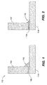
Fig. 1 is a schematic view of an exemplary embodiment of a brazed assembly constructed in accordance with the present disclosure, showing a braze material laser cladded to a first and second component adjacent a void; -
Fig. 2 is a schematic view of the braze assembly ofFig. 1 , showing the braze material forming a braze joint between the first and second components; -
Fig. 3 is a schematic view of another exemplary embodiment of a brazed assembly constructed in accordance with the present disclosure, showing a braze ball crimped into a pocket feature prior to forming a braze joint between the first and second components; -
Fig. 4 is a schematic view of the braze assembly ofFig. 3 , showing the braze material forming a braze joint between the first and second components; -
Fig. 5 is a schematic view of another exemplary embodiment of a brazed assembly constructed in accordance with the present disclosure, showing a preformed braze ball to tack welded in place prior to brazing; and -
Fig. 6 is a schematic view of the braze assembly ofFig. 5 , showing the braze ball consumed between the first and second components to provide a braze joint therebetween. - Reference will now be made to the drawings wherein like reference numerals identify similar structural features or aspects of the subject disclosure. For purposes of explanation and illustration, and not limitation, a partial view of an exemplary embodiment of a method for manufacturing in accordance with the disclosure is shown in
Fig. 1 and is designated generally by reference character 100. Other embodiments of methods of manufacturing in accordance with the disclosure, or aspects thereof, are provided inFigs. 2-3 , as will be described. - With reference to
Figs. 1 and 2 an example of afirst component 112 and asecond component 114 with abraze filler 110 is shown adjacent avoid 116 is shown. First andsecond components second components second components braze filler 110 laser cladded adjacent thevoid 116. Thecomponents braze 110 melts flows into thevoid 116. Abraze joint 118, as shown inFig. 2 is formed between the first and second components after thebraze 110 is cooled. In other words, first andsecond components braze filler 110 are assembled with a laser cladding process prior to heating thecomponents braze filler 110 to form thebraze joint 118. In this manner, the entire assembly, including the first andsecond components braze filler 110 to melt and flow directly into thevoid 116 thereby increasing the ability to control the location, amount, and flow of thebraze filler 110. Typical brazing techniques rely on capillary forces, etc. to provide a relatively uncontrolled flow of braze through or between components to a desired braze joint location. Thus components formed of typical braze techniques are prone to braze fillets and even braze blockages as well as incomplete sealing of various internal passages from one another. Depositing thebraze filler 110 directly adjacent thevoid 116 prior to heating thecomponents braze 110 will flow directly into thevoid 116, precisely where it is intended to flow and thereby avoid the challenges of traditional brazing techniques. Thebraze material 110 can include at least one material including bronze-based matrix materials containing nickel, steel-based matrix materials containing nickel, and steel alloys containing chromium, nickel, molybdenum, silicon, vanadium, carbon, gold, silver, copper, platinum, palladium, or the like. - The
braze material 110 is applied to thefirst component 112 and/or thesecond component 114 using laser cladding. Thebraze material 110 can also be laser cladded to only one of thefirst component 112 or thesecond component 114. The non-joined component can be held in position by some other means such as clamping or ajig to maintain the void. - Laser cladding is a process in which an alloy of cladding material (in the form of a wire, powder, etc.) is applied to a surface to permit accurate, consistent application of material. A concentrated laser beam moves relative to the surface to melt the applied alloy and a thin layer of the surface material to form a cladding that is metallurgically bonded. Laser cladding is similar to thermal spraying in that an energy source is used to melt the alloy that is being applied to a substrate. However, unlike thermal spraying, laser cladding also melts a thin layer of the surface that the alloy is being applied to. This process results in a fused metal and strong metallurgical bond between the cladding and the surface the alloy is applied to. Typically, laser cladding results in an interface with superior bond strength over thermal spraying. Since a concentrated laser beam is used as the heat source, the heat affected zone will be minimal. Any suitable known laser cladding process may be used to deposit the braze material to the joint location without departing from the scope of this disclosure.
-
Figs. 3 and 4 illustrate another embodiment of the present disclosure where the braze filler is abraze ball 110 that is located into avoid 116. In this embodiment, thebraze ball 110 is melted into the twostructural components braze joint 118. It will be understood by those skilled in the art the braze is shown as a braze ball for ease of illustration and description, however the braze can be any shape/form that fits within a desired void without departing from the scope of the present invention.Figs. 5 and 6 illustrate another embodiment of the present disclosure where the braze filler is abraze ball 110 that is used to tack weld and locate the twostructural components braze ball 110 is melted into the twostructural components - As shown in
Figs. 3-6 , thecomponents braze ball 110 are shown as a general assembly. The braze ball can be used on any suitable assembly requiring a braze joint, for example, pump motors, fuel assemblies, turbine engines, or the like. This embodiment allows to control the quantity of the braze material by selecting the proper size of thebraze ball 110. Further, the proper size of thebraze ball 110 allows for additional control over the applied heat quantity based on the operating conditions of the assembly. Thus, the supply of excess heat can be avoided. More specifically, oxidation, discoloration, warping and undesirable stresses are avoided. Due to the precise measuring of the braze material in the form of balls of predetermined size, any waste of braze material is also avoided. As shown inFig. 3 , as the first andsecond components braze ball 110 are heated thebraze ball 110 melts and flows intovoid 116 to a braze joint betweencomponents - The methods and systems of the present disclosure, as described above and shown in the drawings, provide for a method of manufacturing with superior properties including improved precision in brazing. While the apparatus and methods of the subject disclosure have been shown and described with reference to preferred embodiments, those skilled in the art will readily appreciate that changes and/or modifications may be made thereto without departing from the scope of the subject disclosure as defined by the claims.
Claims (11)
- A method of manufacturing, comprising:depositing a braze filler (110) adjacent to a void (116) between a first component (112) and a second component (114) thus holding the components in position before brazing;heating the first and second components to melt the braze filler and draw the braze filler into the void; andforming a braze joint (118) between the first and second components by cooling the braze filler.
- The method of claim 1, wherein depositing includes laser cladding the braze filler to the first and second components adjacent the void.
- The method of claim 1 or 2, further comprising welding the first and second components in position to form the void with the braze filler adjacent to the void.
- The method of any preceding claim, further comprising depositing the braze filler as a powder.
- The method of any preceding claim, further comprising depositing the braze filler as a cold spray.
- The method of any preceding claim, further comprising depositing the braze filler as a melted brazed filament.
- The method of any preceding claim, wherein the depositing includes laser cladding braze filler to the first component and clamping the first component to the second component.
- The method of claim 1, 2 or 3, further comprising locating and/or tack welding the braze filler as a braze ball to the first and second components.
- The method of claim 8, wherein the braze ball is a predetermined size.
- The method of claim 8 or 9, wherein depositing includes locating and/or tack welding the braze ball to the first component and clamping the first component to the second component.
- The method of any preceding claim, wherein the braze material includes at least one material chosen from the group consisting of bronze-based matrix materials containing nickel, steel-based matrix materials containing nickel, and steel alloys containing chromium, nickel, molybdenum, silicon, vanadium, carbon, gold, silver, copper, platinum and/or palladium.
Applications Claiming Priority (1)
| Application Number | Priority Date | Filing Date | Title |
|---|---|---|---|
| US14/704,579 US20160325370A1 (en) | 2015-05-05 | 2015-05-05 | Deposition of braze preform |
Publications (2)
| Publication Number | Publication Date |
|---|---|
| EP3090826A1 true EP3090826A1 (en) | 2016-11-09 |
| EP3090826B1 EP3090826B1 (en) | 2021-11-03 |
Family
ID=55963178
Family Applications (1)
| Application Number | Title | Priority Date | Filing Date |
|---|---|---|---|
| EP16168497.2A Active EP3090826B1 (en) | 2015-05-05 | 2016-05-05 | Deposition of braze preform |
Country Status (2)
| Country | Link |
|---|---|
| US (3) | US20160325370A1 (en) |
| EP (1) | EP3090826B1 (en) |
Cited By (1)
| Publication number | Priority date | Publication date | Assignee | Title |
|---|---|---|---|---|
| CN108941976A (en) * | 2018-09-26 | 2018-12-07 | 西安理工大学 | TA1-Q345 middle layer welding wire and preparation and welding method |
Families Citing this family (4)
| Publication number | Priority date | Publication date | Assignee | Title |
|---|---|---|---|---|
| US10879211B2 (en) * | 2016-06-30 | 2020-12-29 | R.S.M. Electron Power, Inc. | Method of joining a surface-mount component to a substrate with solder that has been temporarily secured |
| US11504801B2 (en) * | 2018-08-24 | 2022-11-22 | Phoenix Laser Solutions | Bimetallic joining with powdered metal fillers |
| CN116529014A (en) * | 2020-10-15 | 2023-08-01 | 南洋理工大学 | Laser additive brazing system and method |
| US11453949B2 (en) | 2020-10-26 | 2022-09-27 | General Electric Company | Methods of forming desired geometry on superalloy part using powder mixture of low and high melt temperature superalloys |
Citations (1)
| Publication number | Priority date | Publication date | Assignee | Title |
|---|---|---|---|---|
| EP1916318A2 (en) * | 2006-10-27 | 2008-04-30 | United Technologies Corporation | Braze pre-placement using cold spray deposition |
Family Cites Families (4)
| Publication number | Priority date | Publication date | Assignee | Title |
|---|---|---|---|---|
| US3222774A (en) * | 1961-03-01 | 1965-12-14 | Curtiss Wright Corp | Method of brazing porous materials |
| JP2004288350A (en) * | 2003-03-03 | 2004-10-14 | Shinka Jitsugyo Kk | Method and apparatus for manufacturing magnetic head device, and magnetic head device |
| JP4018702B2 (en) * | 2005-04-05 | 2007-12-05 | アルプス電気株式会社 | Magnetic head assembly |
| AU2009329094B2 (en) * | 2008-12-18 | 2013-09-12 | Csir | Method of repairing a metallic artefact |
-
2015
- 2015-05-05 US US14/704,579 patent/US20160325370A1/en not_active Abandoned
-
2016
- 2016-05-05 EP EP16168497.2A patent/EP3090826B1/en active Active
-
2017
- 2017-06-22 US US15/630,313 patent/US10252365B2/en active Active
-
2019
- 2019-03-11 US US16/297,944 patent/US20190201995A1/en not_active Abandoned
Patent Citations (1)
| Publication number | Priority date | Publication date | Assignee | Title |
|---|---|---|---|---|
| EP1916318A2 (en) * | 2006-10-27 | 2008-04-30 | United Technologies Corporation | Braze pre-placement using cold spray deposition |
Non-Patent Citations (2)
| Title |
|---|
| R. MUNDT: "TALAT Lecture 4601 Introduction to Brazing of Aluminium Alloys", 31 December 1994 (1994-12-31), pages 1 - 24, XP055291534, Retrieved from the Internet <URL:http://core.materials.ac.uk/repository/eaa/talat/4601.pdf> [retrieved on 20160727] * |
| UNKNOWN: "An Introduction to Brazing - Fundamentals, Materials, Processing An Introduction to Brazing - Issue 4", 30 September 2014 (2014-09-30), pages 1 - 24, XP055291435, Retrieved from the Internet <URL:https://www.oerlikon.com/ecomaXL/files/metco/oerlikon_Introduction_to_Brazing_EN4.pdf&download=1> [retrieved on 20160726] * |
Cited By (1)
| Publication number | Priority date | Publication date | Assignee | Title |
|---|---|---|---|---|
| CN108941976A (en) * | 2018-09-26 | 2018-12-07 | 西安理工大学 | TA1-Q345 middle layer welding wire and preparation and welding method |
Also Published As
| Publication number | Publication date |
|---|---|
| US20190201995A1 (en) | 2019-07-04 |
| EP3090826B1 (en) | 2021-11-03 |
| US20170282273A1 (en) | 2017-10-05 |
| US10252365B2 (en) | 2019-04-09 |
| US20160325370A1 (en) | 2016-11-10 |
Similar Documents
| Publication | Publication Date | Title |
|---|---|---|
| US20190201995A1 (en) | Deposition of braze preform | |
| EP3768453B1 (en) | Method and system for additive manufacturing or repair with in-situ manufacturing and feeding of a sintered wire | |
| JP5602458B2 (en) | Method for joining two metal parts by a tungsten-inert gas welding method and apparatus for carrying out the method | |
| CN110576263B (en) | Dissimilar metal laser cladding welding method for copper pipe and steel pipe | |
| CN105033421B (en) | Dissimilar metal electric arc glue weldering connection system and method | |
| EP3345708B1 (en) | Method of feeding a braze filler to a joint, brazed article, and braze assembly | |
| CN106078093B (en) | The processing method of flanged (FLGD) thin-walled tube-type part | |
| US20160303674A1 (en) | Method for manufacturing a braze joint gap and method for brazing or soldering | |
| CN107073620A (en) | Solder and the method for manufacturing component by the sealed connection of material | |
| EP4506086A2 (en) | Dual-material components and methods of making therefor | |
| US20160325369A1 (en) | Braze cladding | |
| JP2014147973A (en) | Brazing process and plate assembly | |
| CN114192983B (en) | Laser self-fluxing welding method | |
| US20120205351A1 (en) | Stainless steel joining method | |
| JPH09512615A (en) | Method of manufacturing thrust chamber for rocket engine having tubular wall using laser powder injection method | |
| JP2023547321A (en) | Method for forming desired geometries in superalloy parts using powder mixtures of low and high melting point superalloys | |
| US20090032572A1 (en) | System, method, and apparatus for reactive foil brazing of rock bit components. Hardfacing and compacts | |
| CN116213866B (en) | Dissimilar metal joint welding method and dissimilar metal welded joint | |
| US20180161904A1 (en) | Techniques for providing stop-offs for brazing materials or other materials on structures being joined | |
| US3768148A (en) | Method of joining print characters to high speed printer fingers | |
| CN121447294A (en) | Welding method and welding prefabricated member | |
| US12138703B2 (en) | Apparatus and method for hard facing a substrate | |
| DE19648546C2 (en) | Process for soldering parts made of solderable materials | |
| US10166618B2 (en) | Heat stop for brazing or soldering | |
| JP2016217695A (en) | Parts, gas turbine parts and forming method |
Legal Events
| Date | Code | Title | Description |
|---|---|---|---|
| PUAI | Public reference made under article 153(3) epc to a published international application that has entered the european phase |
Free format text: ORIGINAL CODE: 0009012 |
|
| AK | Designated contracting states |
Kind code of ref document: A1 Designated state(s): AL AT BE BG CH CY CZ DE DK EE ES FI FR GB GR HR HU IE IS IT LI LT LU LV MC MK MT NL NO PL PT RO RS SE SI SK SM TR |
|
| AX | Request for extension of the european patent |
Extension state: BA ME |
|
| STAA | Information on the status of an ep patent application or granted ep patent |
Free format text: STATUS: REQUEST FOR EXAMINATION WAS MADE |
|
| 17P | Request for examination filed |
Effective date: 20170509 |
|
| RBV | Designated contracting states (corrected) |
Designated state(s): AL AT BE BG CH CY CZ DE DK EE ES FI FR GB GR HR HU IE IS IT LI LT LU LV MC MK MT NL NO PL PT RO RS SE SI SK SM TR |
|
| GRAP | Despatch of communication of intention to grant a patent |
Free format text: ORIGINAL CODE: EPIDOSNIGR1 |
|
| STAA | Information on the status of an ep patent application or granted ep patent |
Free format text: STATUS: GRANT OF PATENT IS INTENDED |
|
| INTG | Intention to grant announced |
Effective date: 20210521 |
|
| GRAS | Grant fee paid |
Free format text: ORIGINAL CODE: EPIDOSNIGR3 |
|
| GRAA | (expected) grant |
Free format text: ORIGINAL CODE: 0009210 |
|
| STAA | Information on the status of an ep patent application or granted ep patent |
Free format text: STATUS: THE PATENT HAS BEEN GRANTED |
|
| AK | Designated contracting states |
Kind code of ref document: B1 Designated state(s): AL AT BE BG CH CY CZ DE DK EE ES FI FR GB GR HR HU IE IS IT LI LT LU LV MC MK MT NL NO PL PT RO RS SE SI SK SM TR |
|
| REG | Reference to a national code |
Ref country code: GB Ref legal event code: FG4D |
|
| REG | Reference to a national code |
Ref country code: AT Ref legal event code: REF Ref document number: 1443527 Country of ref document: AT Kind code of ref document: T Effective date: 20211115 Ref country code: CH Ref legal event code: EP |
|
| REG | Reference to a national code |
Ref country code: IE Ref legal event code: FG4D |
|
| REG | Reference to a national code |
Ref country code: DE Ref legal event code: R096 Ref document number: 602016065641 Country of ref document: DE |
|
| REG | Reference to a national code |
Ref country code: LT Ref legal event code: MG9D |
|
| REG | Reference to a national code |
Ref country code: NL Ref legal event code: MP Effective date: 20211103 |
|
| REG | Reference to a national code |
Ref country code: AT Ref legal event code: MK05 Ref document number: 1443527 Country of ref document: AT Kind code of ref document: T Effective date: 20211103 |
|
| PG25 | Lapsed in a contracting state [announced via postgrant information from national office to epo] |
Ref country code: RS Free format text: LAPSE BECAUSE OF FAILURE TO SUBMIT A TRANSLATION OF THE DESCRIPTION OR TO PAY THE FEE WITHIN THE PRESCRIBED TIME-LIMIT Effective date: 20211103 Ref country code: LT Free format text: LAPSE BECAUSE OF FAILURE TO SUBMIT A TRANSLATION OF THE DESCRIPTION OR TO PAY THE FEE WITHIN THE PRESCRIBED TIME-LIMIT Effective date: 20211103 Ref country code: FI Free format text: LAPSE BECAUSE OF FAILURE TO SUBMIT A TRANSLATION OF THE DESCRIPTION OR TO PAY THE FEE WITHIN THE PRESCRIBED TIME-LIMIT Effective date: 20211103 Ref country code: BG Free format text: LAPSE BECAUSE OF FAILURE TO SUBMIT A TRANSLATION OF THE DESCRIPTION OR TO PAY THE FEE WITHIN THE PRESCRIBED TIME-LIMIT Effective date: 20220203 Ref country code: AT Free format text: LAPSE BECAUSE OF FAILURE TO SUBMIT A TRANSLATION OF THE DESCRIPTION OR TO PAY THE FEE WITHIN THE PRESCRIBED TIME-LIMIT Effective date: 20211103 |
|
| RAP4 | Party data changed (patent owner data changed or rights of a patent transferred) |
Owner name: COLLINS ENGINE NOZZLES, INC. |
|
| PG25 | Lapsed in a contracting state [announced via postgrant information from national office to epo] |
Ref country code: IS Free format text: LAPSE BECAUSE OF FAILURE TO SUBMIT A TRANSLATION OF THE DESCRIPTION OR TO PAY THE FEE WITHIN THE PRESCRIBED TIME-LIMIT Effective date: 20220303 Ref country code: SE Free format text: LAPSE BECAUSE OF FAILURE TO SUBMIT A TRANSLATION OF THE DESCRIPTION OR TO PAY THE FEE WITHIN THE PRESCRIBED TIME-LIMIT Effective date: 20211103 Ref country code: PT Free format text: LAPSE BECAUSE OF FAILURE TO SUBMIT A TRANSLATION OF THE DESCRIPTION OR TO PAY THE FEE WITHIN THE PRESCRIBED TIME-LIMIT Effective date: 20220303 Ref country code: PL Free format text: LAPSE BECAUSE OF FAILURE TO SUBMIT A TRANSLATION OF THE DESCRIPTION OR TO PAY THE FEE WITHIN THE PRESCRIBED TIME-LIMIT Effective date: 20211103 Ref country code: NO Free format text: LAPSE BECAUSE OF FAILURE TO SUBMIT A TRANSLATION OF THE DESCRIPTION OR TO PAY THE FEE WITHIN THE PRESCRIBED TIME-LIMIT Effective date: 20220203 Ref country code: NL Free format text: LAPSE BECAUSE OF FAILURE TO SUBMIT A TRANSLATION OF THE DESCRIPTION OR TO PAY THE FEE WITHIN THE PRESCRIBED TIME-LIMIT Effective date: 20211103 Ref country code: LV Free format text: LAPSE BECAUSE OF FAILURE TO SUBMIT A TRANSLATION OF THE DESCRIPTION OR TO PAY THE FEE WITHIN THE PRESCRIBED TIME-LIMIT Effective date: 20211103 Ref country code: HR Free format text: LAPSE BECAUSE OF FAILURE TO SUBMIT A TRANSLATION OF THE DESCRIPTION OR TO PAY THE FEE WITHIN THE PRESCRIBED TIME-LIMIT Effective date: 20211103 Ref country code: GR Free format text: LAPSE BECAUSE OF FAILURE TO SUBMIT A TRANSLATION OF THE DESCRIPTION OR TO PAY THE FEE WITHIN THE PRESCRIBED TIME-LIMIT Effective date: 20220204 Ref country code: ES Free format text: LAPSE BECAUSE OF FAILURE TO SUBMIT A TRANSLATION OF THE DESCRIPTION OR TO PAY THE FEE WITHIN THE PRESCRIBED TIME-LIMIT Effective date: 20211103 |
|
| PG25 | Lapsed in a contracting state [announced via postgrant information from national office to epo] |
Ref country code: SM Free format text: LAPSE BECAUSE OF FAILURE TO SUBMIT A TRANSLATION OF THE DESCRIPTION OR TO PAY THE FEE WITHIN THE PRESCRIBED TIME-LIMIT Effective date: 20211103 Ref country code: SK Free format text: LAPSE BECAUSE OF FAILURE TO SUBMIT A TRANSLATION OF THE DESCRIPTION OR TO PAY THE FEE WITHIN THE PRESCRIBED TIME-LIMIT Effective date: 20211103 Ref country code: RO Free format text: LAPSE BECAUSE OF FAILURE TO SUBMIT A TRANSLATION OF THE DESCRIPTION OR TO PAY THE FEE WITHIN THE PRESCRIBED TIME-LIMIT Effective date: 20211103 Ref country code: EE Free format text: LAPSE BECAUSE OF FAILURE TO SUBMIT A TRANSLATION OF THE DESCRIPTION OR TO PAY THE FEE WITHIN THE PRESCRIBED TIME-LIMIT Effective date: 20211103 Ref country code: DK Free format text: LAPSE BECAUSE OF FAILURE TO SUBMIT A TRANSLATION OF THE DESCRIPTION OR TO PAY THE FEE WITHIN THE PRESCRIBED TIME-LIMIT Effective date: 20211103 Ref country code: CZ Free format text: LAPSE BECAUSE OF FAILURE TO SUBMIT A TRANSLATION OF THE DESCRIPTION OR TO PAY THE FEE WITHIN THE PRESCRIBED TIME-LIMIT Effective date: 20211103 |
|
| REG | Reference to a national code |
Ref country code: DE Ref legal event code: R097 Ref document number: 602016065641 Country of ref document: DE |
|
| PLBE | No opposition filed within time limit |
Free format text: ORIGINAL CODE: 0009261 |
|
| STAA | Information on the status of an ep patent application or granted ep patent |
Free format text: STATUS: NO OPPOSITION FILED WITHIN TIME LIMIT |
|
| 26N | No opposition filed |
Effective date: 20220804 |
|
| PG25 | Lapsed in a contracting state [announced via postgrant information from national office to epo] |
Ref country code: AL Free format text: LAPSE BECAUSE OF FAILURE TO SUBMIT A TRANSLATION OF THE DESCRIPTION OR TO PAY THE FEE WITHIN THE PRESCRIBED TIME-LIMIT Effective date: 20211103 |
|
| PG25 | Lapsed in a contracting state [announced via postgrant information from national office to epo] |
Ref country code: SI Free format text: LAPSE BECAUSE OF FAILURE TO SUBMIT A TRANSLATION OF THE DESCRIPTION OR TO PAY THE FEE WITHIN THE PRESCRIBED TIME-LIMIT Effective date: 20211103 |
|
| REG | Reference to a national code |
Ref country code: CH Ref legal event code: PL |
|
| REG | Reference to a national code |
Ref country code: BE Ref legal event code: MM Effective date: 20220531 |
|
| PG25 | Lapsed in a contracting state [announced via postgrant information from national office to epo] |
Ref country code: MC Free format text: LAPSE BECAUSE OF FAILURE TO SUBMIT A TRANSLATION OF THE DESCRIPTION OR TO PAY THE FEE WITHIN THE PRESCRIBED TIME-LIMIT Effective date: 20211103 Ref country code: LU Free format text: LAPSE BECAUSE OF NON-PAYMENT OF DUE FEES Effective date: 20220505 Ref country code: LI Free format text: LAPSE BECAUSE OF NON-PAYMENT OF DUE FEES Effective date: 20220531 Ref country code: CH Free format text: LAPSE BECAUSE OF NON-PAYMENT OF DUE FEES Effective date: 20220531 |
|
| PG25 | Lapsed in a contracting state [announced via postgrant information from national office to epo] |
Ref country code: IE Free format text: LAPSE BECAUSE OF NON-PAYMENT OF DUE FEES Effective date: 20220505 |
|
| PG25 | Lapsed in a contracting state [announced via postgrant information from national office to epo] |
Ref country code: IT Free format text: LAPSE BECAUSE OF FAILURE TO SUBMIT A TRANSLATION OF THE DESCRIPTION OR TO PAY THE FEE WITHIN THE PRESCRIBED TIME-LIMIT Effective date: 20211103 Ref country code: BE Free format text: LAPSE BECAUSE OF NON-PAYMENT OF DUE FEES Effective date: 20220531 |
|
| P01 | Opt-out of the competence of the unified patent court (upc) registered |
Effective date: 20230530 |
|
| PG25 | Lapsed in a contracting state [announced via postgrant information from national office to epo] |
Ref country code: HU Free format text: LAPSE BECAUSE OF FAILURE TO SUBMIT A TRANSLATION OF THE DESCRIPTION OR TO PAY THE FEE WITHIN THE PRESCRIBED TIME-LIMIT; INVALID AB INITIO Effective date: 20160505 |
|
| PG25 | Lapsed in a contracting state [announced via postgrant information from national office to epo] |
Ref country code: MK Free format text: LAPSE BECAUSE OF FAILURE TO SUBMIT A TRANSLATION OF THE DESCRIPTION OR TO PAY THE FEE WITHIN THE PRESCRIBED TIME-LIMIT Effective date: 20211103 Ref country code: CY Free format text: LAPSE BECAUSE OF FAILURE TO SUBMIT A TRANSLATION OF THE DESCRIPTION OR TO PAY THE FEE WITHIN THE PRESCRIBED TIME-LIMIT Effective date: 20211103 |
|
| PG25 | Lapsed in a contracting state [announced via postgrant information from national office to epo] |
Ref country code: MT Free format text: LAPSE BECAUSE OF FAILURE TO SUBMIT A TRANSLATION OF THE DESCRIPTION OR TO PAY THE FEE WITHIN THE PRESCRIBED TIME-LIMIT Effective date: 20211103 |
|
| PG25 | Lapsed in a contracting state [announced via postgrant information from national office to epo] |
Ref country code: TR Free format text: LAPSE BECAUSE OF FAILURE TO SUBMIT A TRANSLATION OF THE DESCRIPTION OR TO PAY THE FEE WITHIN THE PRESCRIBED TIME-LIMIT Effective date: 20211103 |
|
| PGFP | Annual fee paid to national office [announced via postgrant information from national office to epo] |
Ref country code: GB Payment date: 20260421 Year of fee payment: 11 |
|
| PGFP | Annual fee paid to national office [announced via postgrant information from national office to epo] |
Ref country code: DE Payment date: 20260421 Year of fee payment: 11 |
|
| PGFP | Annual fee paid to national office [announced via postgrant information from national office to epo] |
Ref country code: FR Payment date: 20260422 Year of fee payment: 11 |