EP3090149B1 - Handling device - Google Patents
Handling device Download PDFInfo
- Publication number
- EP3090149B1 EP3090149B1 EP15700447.4A EP15700447A EP3090149B1 EP 3090149 B1 EP3090149 B1 EP 3090149B1 EP 15700447 A EP15700447 A EP 15700447A EP 3090149 B1 EP3090149 B1 EP 3090149B1
- Authority
- EP
- European Patent Office
- Prior art keywords
- burner
- handling device
- base body
- handling
- foregoing
- Prior art date
- Legal status (The legal status is an assumption and is not a legal conclusion. Google has not performed a legal analysis and makes no representation as to the accuracy of the status listed.)
- Active
Links
Images




Classifications
-
- F—MECHANICAL ENGINEERING; LIGHTING; HEATING; WEAPONS; BLASTING
- F01—MACHINES OR ENGINES IN GENERAL; ENGINE PLANTS IN GENERAL; STEAM ENGINES
- F01D—NON-POSITIVE DISPLACEMENT MACHINES OR ENGINES, e.g. STEAM TURBINES
- F01D25/00—Component parts, details, or accessories, not provided for in, or of interest apart from, other groups
- F01D25/28—Supporting or mounting arrangements, e.g. for turbine casing
- F01D25/285—Temporary support structures, e.g. for testing, assembling, installing, repairing; Assembly methods using such structures
-
- F—MECHANICAL ENGINEERING; LIGHTING; HEATING; WEAPONS; BLASTING
- F02—COMBUSTION ENGINES; HOT-GAS OR COMBUSTION-PRODUCT ENGINE PLANTS
- F02C—GAS-TURBINE PLANTS; AIR INTAKES FOR JET-PROPULSION PLANTS; CONTROLLING FUEL SUPPLY IN AIR-BREATHING JET-PROPULSION PLANTS
- F02C7/00—Features, components parts, details or accessories, not provided for in, or of interest apart form groups F02C1/00 - F02C6/00; Air intakes for jet-propulsion plants
- F02C7/26—Starting; Ignition
- F02C7/264—Ignition
-
- F—MECHANICAL ENGINEERING; LIGHTING; HEATING; WEAPONS; BLASTING
- F23—COMBUSTION APPARATUS; COMBUSTION PROCESSES
- F23R—GENERATING COMBUSTION PRODUCTS OF HIGH PRESSURE OR HIGH VELOCITY, e.g. GAS-TURBINE COMBUSTION CHAMBERS
- F23R3/00—Continuous combustion chambers using liquid or gaseous fuel
- F23R3/42—Continuous combustion chambers using liquid or gaseous fuel characterised by the arrangement or form of the flame tubes or combustion chambers
- F23R3/60—Support structures; Attaching or mounting means
-
- F—MECHANICAL ENGINEERING; LIGHTING; HEATING; WEAPONS; BLASTING
- F05—INDEXING SCHEMES RELATING TO ENGINES OR PUMPS IN VARIOUS SUBCLASSES OF CLASSES F01-F04
- F05D—INDEXING SCHEME FOR ASPECTS RELATING TO NON-POSITIVE-DISPLACEMENT MACHINES OR ENGINES, GAS-TURBINES OR JET-PROPULSION PLANTS
- F05D2220/00—Application
- F05D2220/30—Application in turbines
- F05D2220/32—Application in turbines in gas turbines
-
- F—MECHANICAL ENGINEERING; LIGHTING; HEATING; WEAPONS; BLASTING
- F05—INDEXING SCHEMES RELATING TO ENGINES OR PUMPS IN VARIOUS SUBCLASSES OF CLASSES F01-F04
- F05D—INDEXING SCHEME FOR ASPECTS RELATING TO NON-POSITIVE-DISPLACEMENT MACHINES OR ENGINES, GAS-TURBINES OR JET-PROPULSION PLANTS
- F05D2230/00—Manufacture
- F05D2230/60—Assembly methods
- F05D2230/68—Assembly methods using auxiliary equipment for lifting or holding
-
- F—MECHANICAL ENGINEERING; LIGHTING; HEATING; WEAPONS; BLASTING
- F05—INDEXING SCHEMES RELATING TO ENGINES OR PUMPS IN VARIOUS SUBCLASSES OF CLASSES F01-F04
- F05D—INDEXING SCHEME FOR ASPECTS RELATING TO NON-POSITIVE-DISPLACEMENT MACHINES OR ENGINES, GAS-TURBINES OR JET-PROPULSION PLANTS
- F05D2230/00—Manufacture
- F05D2230/70—Disassembly methods
-
- F—MECHANICAL ENGINEERING; LIGHTING; HEATING; WEAPONS; BLASTING
- F23—COMBUSTION APPARATUS; COMBUSTION PROCESSES
- F23R—GENERATING COMBUSTION PRODUCTS OF HIGH PRESSURE OR HIGH VELOCITY, e.g. GAS-TURBINE COMBUSTION CHAMBERS
- F23R2900/00—Special features of, or arrangements for continuous combustion chambers; Combustion processes therefor
- F23R2900/00019—Repairing or maintaining combustion chamber liners or subparts
Definitions
- the present invention relates to a handling device for handling a burner of a stationary gas turbine during assembly and disassembly.
- Stationary gas turbines are known in prior art. They normally comprise a plurality of burners, which are inserted in burner receiving openings of the turbine housing.
- the receiving openings are arranged at equal intervals along the perimeter of a ring surface, which is inclined with respect to the longitudinal axis of the turbine housing. Accordingly, the burner receiving openings have a plurality of different orientations demanding a high positioning flexibility of a handling device, which is used for handling the heavy burners during their assembly and disassembly.
- EP-A-2 070 663 A burner handling and lifting device realizing such a positioning is described e.g. in EP-A-2 070 663 .
- This device comprises a supporting structure, a movable grappler fixed to the supporting structure and a burner fixture, which is arranged at the free end of the grappler and configured to receive a burner to be handled.
- the supporting structure, the grappler and the burner fixture provide three translational degrees of freedom and at least two degrees of freedom of the orientation of a burner fixed to the burner fixture.
- EP-A-2 070 663 proposes a robotic device for handling a burner during its assembly or disassembly.
- the installation of such a robotic device prior to the assembly or disassembly of a burner is very time-consuming and cumbersome.
- robotic devices of the mentioned type are very expensive.
- a further burner handling and lifting device is disclosed in GB 2 306 155 A .
- a handling device for handling a burner of a stationary gas turbine during assembly and disassembly, comprising a base body having at least one contact surface designed to contact a rear end surface of a burner, fixing means for fixing the base body to said rear end surface of the burner, two arms fixed to and protruding from said base body to different sides of the contact surface, wherein each arm is provided with receiving means, which are designed for removably receiving a fixing component of a lifting appliance, such as a hook or a belt of a crane or the like, and which are spaced apart from each other in the longitudinal direction of a burner during its handling.
- a fixing component of a lifting appliance such as a hook or a belt of a crane or the like
- the present invention provides some kind of a lifting bracket, which on the one hand can be fixed to a burner and on the other hand can be picked up by a lifting appliance. Thanks to its little weight and small dimensions, the handling device according to the present invention is easy to transport and to handle. Moreover, the manufacture of the handling device is inexpensive. Thanks to the fact, that the receiving means provided at the arms are spaced apart from each other in the longitudinal direction of a burner during its handling, a burner can be held in many different orientations, whereby the needed positioning flexibility is realized. According to the present invention the arms are rotatably fixed to the base body and are lockable in different rotating positions, in particular by means of quick release pins. Thus, the rotating position of the arms can be adapted to different situations of use.
- the fixing means comprise at least one screw.
- the usage of screws enables an easy and inexpensive fixation of the handling device to a burner to be handled.
- the base body comprises at least one slot hole for receiving the at least one screw, said slot hole preferably extending along a predetermined circular arc corresponding to a screw-hole circle arranged at the rear end surface of a burner.
- the at least one slot hole allows an easy handling of the handling device while fastening the contact surface to the rear end surface of the burner.
- the slot hole is arranged adjacent to the contact surface.
- the base body is provided with additional protruding fixing pins, which are inserted in corresponding holes provided at the rear end surface of the burner.
- fixing pins stabilize the connection between the handling device and the burner to be handled.
- the fixing pins may be used to adjust the handling device with respect to the burner before its base body is fastened thereto.
- the contact surface draws an angle of 80° to 90° with each arm in at least one operating position of the arms. Accordingly, the receiving means can be positioned far away from each other in this operating position.
- the arms are rotatable at least from 0° to 90° with respect to the contact surface. Accordingly, the arms of the handling device can be folded in order to simplify the transport of the handling device.
- the position of one receiving means is chosen in such a manner, that it is or can be situated radially above the balance point of the burner during its handling. This simplifies the handling of the burner in a horizontal orientation.
- the receiving means are advantageously provided close to the free end of each arm.
- the receiving means are provided as shackles.
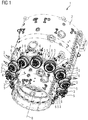
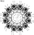
- FIG. 1 and 2 shows a part of an exemplary stationary gas turbine 1, which is known in prior art.
- the stationary gas turbine 1 comprises a turbine housing 2 and twelve burners 3, which are inserted in allocated burner receiving openings 4 of the turbine housing 2 at positions P1 to P12 and are screwed at flange portions 5 provided at the rear end of each burner 3 with essentially cylindrical shells 6 attached to the turbine housing 2.
- the burner receiving openings 4 are arranged at equal intervals along the perimeter of a ring surface 7 of the turbine housing 2, which is inclined with respect to a longitudinal axis 8 of the turbine housing 2. Accordingly, the burner receiving openings 4 and the burners 3 inserted therein have a plurality of different orientations.
- the respective inclination angles with respect to a horizontal plane 9 of the burners 3 at the positions P1 and P12 are different to the respective inclination angles of the burners 3 at the positions P2 and P11, which again differ from the respective inclination angles of the burners 3 at the positions P3 and P10.
- This plurality of different orientations of the burners 3 demands a high positioning flexibility of a handling device, which is used for handling the heavy burners 3 during their assembly and disassembly.
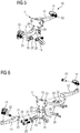
- FIGS 3 to 6 show a handling device 10 according to an embodiment of the present invention, which can be used for handling the burners 3 of the stationary gas turbine 1 during their assembly and disassembly.
- the handling device 10 comprises as main components a base body 11 and two arms 12 and 13 fixed to and protruding from the base body 11 in opposite directions, wherein each arm 12, 13 is provided with a receiving means 14, 15 being designed for removably receiving a fixing component of a lifting appliance as it is described later.
- the base body 11 comprises a front side 16 and a rear side 17. In the middle portion of the front side 16, the base body 11 defines a contact surface 18 designed to contact a rear end surface of the burners 3.
- the lower portion of the base body 11 has the form of a shackle comprising two slot holes 19 being dimensioned to receive screws 20, which are provided with appropriate washers 21.
- the slot holes 19 extend along a predetermined circular arc corresponding to a screw-hole circle arranged at the rear end surface of each burner 3.
- the front side 16 of the base body 11 is provided with protruding fixing pins 22, which are arranged and dimensioned for being received in corresponding receiving bores 23 provided at the rear end surface of each burner 3.
- the upper portion of the front side 16 of base body 11 is provided with two arm receiving projections 23, which are spaced apart from each other for receiving the first arm 12, and which define a bearing face 25 for the first arm 12 in between.
- At the free end of the first arm 12 facing to the base body 11 are provided three through holes 26, which are arranged in L-shape and can be brought in coverage with two through holes 27, which are provided about each other in each of the arm receiving projections 24, respectively, in order to fix the first arm 12 to the arm receiving projections 24 by means of quick release pins 28. Thanks to the L-shaped arrangement of the through holes 26, the first arm 12 can be connected to the arm receiving projections 24 in two positions. In the first position, the first arm 12 backwardly projects from the base body 11 essentially at right angle.
- the first arm 12 projects upwardly from the base body 11.
- the second arm 13 is fixed to the front side 16 of base body in a corresponding fashion by means of arm receiving projections 29.
- the arm receiving projections 29 are spaced apart from each other for receiving the second arm 13 and define a bearing face 30 for the second arm 13 in between.
- At the free end of the second arm 13 facing to the base body 11 are provided three through holes 31, which are arranged in L-shape and can be brought in coverage with two through holes 32, which are provided about each other in each of the arm receiving projections 29, respectively, in order to fix the second arm 13 to the arm receiving projections 29 by means of quick release pins 28.
- the second arm 13 can be connected to the arm receiving projections 29 in two positions. In the first position, the second arm 13 forwardly projects from the base body 11 essentially at right angle. In the second position, the second arm 13 projects upwardly from the base body 11. Accordingly, when both arms 12 and 13 are arranged in their first position, they protruding from the base body 11 to different sides of the contact surface 18.
- the arms 12 and 13 comprise at their outer free ends the receiving means 14, 15, which are provided as shackles.
- the receiving means 14, 15 are fixed to the arms 12 and 13 by means of quick release bolts 33, which are inserted in corresponding through bores 25 provided in the arms 12 and 13.
- the fixing pins 22 provided at the front side 16 of the base body 11 are firstly inserted in the corresponding receiving bores 23 arranged at the rear end surface of the burner 3. Subsequently, the screws 20 are inserted in the slot holes 19 and are screwed into corresponding screw holes of the screw-hole-circle arranged at the rear end surface of the burner 3. After the tightening of the screws 20 the handling device 10 is fastened to the burner 3.
- Figures 8 to 11 show different orientations of a burner 3 held by belts 34 and 35, which can be realized by changing the length of the belts 34 and 35, such that the belts 34 and 35 draw different angles ⁇ , as it is described in the following.
- the burner 3 can be orientated in a horizontal position as shown in figure 8 , when the belts 34 and 35 define an angle ⁇ 0 .
- This first inclined position corresponds to the orientation of the burner 3 at positions P1 and P12 in figure 2 .
- a second inclined position shown in figure 10 which corresponds to the orientation of the burners 3 at positions P2 and P11 in figure 2 , can be realized, when the belts 34 and 35 form an angle ⁇ 2 .
- a third inclined position shown in figure 11 which corresponds to the orientation of the burners 3 in positions P3 and P10, can be realized, when the belts 34 and 35 form an angle ⁇ 3 .
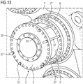
- Figures 12 to 14 show the removal of the burner 3 being arranged at position P3 of figure 2 .
- a first step as shown in figure 12 , the burner 3 is jacked out from the allocated burner receiving opening 4 by a predetermined distance using a known jacking hardware and a plurality of threaded rods 37, which presently will not be described in detail.
- the handling device 10 is attached to the rear end surface of the burner 3 as it was described with reference to figure 7 before. Moreover, belts 33 and 35 are fastened to the receiving means 14 and 15 of the handling device 10, wherein the length of the belts 34 and 35 is chosen in such a manner that the third inclined position according to figure 11 is realized.
- the burner 3 is removed from the turbine housing 2 by means of lifting appliance, such as a crane.
- the handling device 10 is easy to transport and to handle. Moreover, the manufacture of the handling device 10 is inexpensive. Due to the fact, that the receiving means 14, 15 provided at the arms 12, 13 are spaced apart from each other in the longitudinal direction of a burner 3 during its handling, a burner 3 can be held in many different orientations, whereby the needed positioning flexibility is realized.
Landscapes
- Engineering & Computer Science (AREA)
- Mechanical Engineering (AREA)
- General Engineering & Computer Science (AREA)
- Chemical & Material Sciences (AREA)
- Combustion & Propulsion (AREA)
- Load-Engaging Elements For Cranes (AREA)
Description
- The present invention relates to a handling device for handling a burner of a stationary gas turbine during assembly and disassembly.
- Stationary gas turbines are known in prior art. They normally comprise a plurality of burners, which are inserted in burner receiving openings of the turbine housing. The receiving openings are arranged at equal intervals along the perimeter of a ring surface, which is inclined with respect to the longitudinal axis of the turbine housing. Accordingly, the burner receiving openings have a plurality of different orientations demanding a high positioning flexibility of a handling device, which is used for handling the heavy burners during their assembly and disassembly.
- A burner handling and lifting device realizing such a positioning is described e.g. in
EP-A-2 070 663 . This device comprises a supporting structure, a movable grappler fixed to the supporting structure and a burner fixture, which is arranged at the free end of the grappler and configured to receive a burner to be handled. The supporting structure, the grappler and the burner fixture provide three translational degrees of freedom and at least two degrees of freedom of the orientation of a burner fixed to the burner fixture. Accordingly,EP-A-2 070 663 proposes a robotic device for handling a burner during its assembly or disassembly. However, the installation of such a robotic device prior to the assembly or disassembly of a burner is very time-consuming and cumbersome. Moreover, robotic devices of the mentioned type are very expensive. - A further burner handling and lifting device is disclosed in
GB 2 306 155 A - Starting from this prior art it is an object of the present invention to provide handling device of the above-mentioned type, which has a simple and inexpensive construction and is easy to handle.
- In order to solve this object the present invention provides a handling device for handling a burner of a stationary gas turbine during assembly and disassembly, comprising a base body having at least one contact surface designed to contact a rear end surface of a burner, fixing means for fixing the base body to said rear end surface of the burner, two arms fixed to and protruding from said base body to different sides of the contact surface, wherein each arm is provided with receiving means, which are designed for removably receiving a fixing component of a lifting appliance, such as a hook or a belt of a crane or the like, and which are spaced apart from each other in the longitudinal direction of a burner during its handling. In other words the present invention provides some kind of a lifting bracket, which on the one hand can be fixed to a burner and on the other hand can be picked up by a lifting appliance. Thanks to its little weight and small dimensions, the handling device according to the present invention is easy to transport and to handle. Moreover, the manufacture of the handling device is inexpensive. Thanks to the fact, that the receiving means provided at the arms are spaced apart from each other in the longitudinal direction of a burner during its handling, a burner can be held in many different orientations, whereby the needed positioning flexibility is realized. According to the present invention the arms are rotatably fixed to the base body and are lockable in different rotating positions, in particular by means of quick release pins. Thus, the rotating position of the arms can be adapted to different situations of use.
- According to one embodiment of the handling device of the present invention the fixing means comprise at least one screw. The usage of screws enables an easy and inexpensive fixation of the handling device to a burner to be handled. Preferably, the base body comprises at least one slot hole for receiving the at least one screw, said slot hole preferably extending along a predetermined circular arc corresponding to a screw-hole circle arranged at the rear end surface of a burner. The at least one slot hole allows an easy handling of the handling device while fastening the contact surface to the rear end surface of the burner.
- According to one embodiment of the present invention the slot hole is arranged adjacent to the contact surface.
- Preferably, the base body is provided with additional protruding fixing pins, which are inserted in corresponding holes provided at the rear end surface of the burner. Such fixing pins stabilize the connection between the handling device and the burner to be handled. Moreover, the fixing pins may be used to adjust the handling device with respect to the burner before its base body is fastened thereto.
- According to one embodiment of the present invention the contact surface draws an angle of 80° to 90° with each arm in at least one operating position of the arms. Accordingly, the receiving means can be positioned far away from each other in this operating position.
- Preferably, the arms are rotatable at least from 0° to 90° with respect to the contact surface. Accordingly, the arms of the handling device can be folded in order to simplify the transport of the handling device.
- According to one embodiment of the present invention the position of one receiving means is chosen in such a manner, that it is or can be situated radially above the balance point of the burner during its handling. This simplifies the handling of the burner in a horizontal orientation.
- The receiving means are advantageously provided close to the free end of each arm.
- Preferably, the receiving means are provided as shackles.
- Further features and advantages of the present invention become apparent from the following description of a handling device according to an embodiment of the present invention with reference to the accompanying drawing.
- In the drawing
- Figure 1
- is a partial perspective view of a stationary gas turbine comprising several burners;
- Figure 2
- is a rear view of the gas turbine shown in
figure 1 ; - Figure 3
- is a perspective front view of a handling device according to an embodiment of the present invention;
- Figure 4
- is an exploded front view of the handling device shown in
figure 3 ; - Figure 5
- is a perspective rear view of the handling device shown in
figures 3 and 4 ; - Figure 6
- is an exploded rear view of the handling device shown in
figures 3 to 5 ; - Figure 7
- is a perspective rear view of a burner of the stationary gas turbine shown in
figures 1 and2 , to which the handling device according tofigures 3 to 6 is fixed; - Figure 8
- is a side view of the arrangement shown in
figure 7 , wherein the burner is held in a horizontal orientation by means of a fixing component of a lifting appliance; - Figure 9
- is a side view of the arrangement shown in
figure 7 , wherein the burner is held in a first inclined position by means of fixing component of a lifting appliance; - Figure 10
- is a side view of the arrangement shown in
figure 7 , wherein the burner is held in a second inclined position by means of fixing component of a lifting appliance; - Figure 11
- is a side view of the arrangement shown in
figure 7 , wherein the burner is held in a third inclined position by means of fixing component of a lifting appliance; - Figure 12
- is a perspective partial view of the arrangement shown in
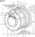
figures 1 and2 showing a burner, which is jacked out by a predetermined amount from its allocated burner receiving opening; - Figure 13
- corresponds to
figure 12 , wherein the handling device shown infigures 3 to 5 is fixed to the burner; and - Figure 14
- is a perspective partial view of the arrangement shown in
figure 13 , wherein the burner is completely jacked out from its allocated burner receiving opening by means of a fixing component of a lifting appliance coupled to the handling device. -
Figures 1 and2 shows a part of an exemplarystationary gas turbine 1, which is known in prior art. Thestationary gas turbine 1 comprises aturbine housing 2 and twelveburners 3, which are inserted in allocatedburner receiving openings 4 of theturbine housing 2 at positions P1 to P12 and are screwed atflange portions 5 provided at the rear end of eachburner 3 with essentiallycylindrical shells 6 attached to theturbine housing 2. Theburner receiving openings 4 are arranged at equal intervals along the perimeter of aring surface 7 of theturbine housing 2, which is inclined with respect to alongitudinal axis 8 of theturbine housing 2. Accordingly, theburner receiving openings 4 and theburners 3 inserted therein have a plurality of different orientations. For example, the respective inclination angles with respect to ahorizontal plane 9 of theburners 3 at the positions P1 and P12 are different to the respective inclination angles of theburners 3 at the positions P2 and P11, which again differ from the respective inclination angles of theburners 3 at the positions P3 and P10. This plurality of different orientations of theburners 3 demands a high positioning flexibility of a handling device, which is used for handling theheavy burners 3 during their assembly and disassembly. -
Figures 3 to 6 show ahandling device 10 according to an embodiment of the present invention, which can be used for handling theburners 3 of thestationary gas turbine 1 during their assembly and disassembly. The handlingdevice 10 comprises as main components abase body 11 and twoarms base body 11 in opposite directions, wherein eacharm - The
base body 11 comprises afront side 16 and arear side 17. In the middle portion of thefront side 16, thebase body 11 defines acontact surface 18 designed to contact a rear end surface of theburners 3. The lower portion of thebase body 11 has the form of a shackle comprising twoslot holes 19 being dimensioned to receivescrews 20, which are provided withappropriate washers 21. The slot holes 19 extend along a predetermined circular arc corresponding to a screw-hole circle arranged at the rear end surface of eachburner 3. Above thecontact surface 18 thefront side 16 of thebase body 11 is provided with protruding fixing pins 22, which are arranged and dimensioned for being received in corresponding receiving bores 23 provided at the rear end surface of eachburner 3. The upper portion of thefront side 16 ofbase body 11 is provided with twoarm receiving projections 23, which are spaced apart from each other for receiving thefirst arm 12, and which define abearing face 25 for thefirst arm 12 in between. At the free end of thefirst arm 12 facing to thebase body 11 are provided three throughholes 26, which are arranged in L-shape and can be brought in coverage with two throughholes 27, which are provided about each other in each of the arm receiving projections 24, respectively, in order to fix thefirst arm 12 to the arm receiving projections 24 by means of quick release pins 28. Thanks to the L-shaped arrangement of the throughholes 26, thefirst arm 12 can be connected to the arm receiving projections 24 in two positions. In the first position, thefirst arm 12 backwardly projects from thebase body 11 essentially at right angle. In the second position, thefirst arm 12 projects upwardly from thebase body 11. Thesecond arm 13 is fixed to thefront side 16 of base body in a corresponding fashion by means ofarm receiving projections 29. Thearm receiving projections 29 are spaced apart from each other for receiving thesecond arm 13 and define abearing face 30 for thesecond arm 13 in between. At the free end of thesecond arm 13 facing to thebase body 11 are provided three throughholes 31, which are arranged in L-shape and can be brought in coverage with two throughholes 32, which are provided about each other in each of thearm receiving projections 29, respectively, in order to fix thesecond arm 13 to thearm receiving projections 29 by means of quick release pins 28. Thanks to the L-shaped arrangement of the throughholes 31, thesecond arm 13 can be connected to thearm receiving projections 29 in two positions. In the first position, thesecond arm 13 forwardly projects from thebase body 11 essentially at right angle. In the second position, thesecond arm 13 projects upwardly from thebase body 11. Accordingly, when botharms base body 11 to different sides of thecontact surface 18. Thearms arms quick release bolts 33, which are inserted in corresponding throughbores 25 provided in thearms - In order to fix the
handling device 10 to aburner 3, as shown infigure 7 , the fixing pins 22 provided at thefront side 16 of thebase body 11 are firstly inserted in the corresponding receiving bores 23 arranged at the rear end surface of theburner 3. Subsequently, thescrews 20 are inserted in the slot holes 19 and are screwed into corresponding screw holes of the screw-hole-circle arranged at the rear end surface of theburner 3. After the tightening of thescrews 20 thehandling device 10 is fastened to theburner 3. -
Figures 8 to 11 show different orientations of aburner 3 held bybelts belts belts - Thanks to the fact that the position of the receiving means 15 of the
second arm 13 is chosen in such a manner, that it is situated radially above thebalance point 36 of theburner 3, theburner 3 can be orientated in a horizontal position as shown infigure 8 , when thebelts - A first inclined position of the
burner 3, which is shown infigure 9 , can be realized, whenbelts burner 3 at positions P1 and P12 infigure 2 . - A second inclined position shown in
figure 10 , which corresponds to the orientation of theburners 3 at positions P2 and P11 infigure 2 , can be realized, when thebelts - A third inclined position shown in
figure 11 , which corresponds to the orientation of theburners 3 in positions P3 and P10, can be realized, when thebelts -
Figures 12 to 14 show the removal of theburner 3 being arranged at position P3 offigure 2 . - In a first step, as shown in
figure 12 , theburner 3 is jacked out from the allocatedburner receiving opening 4 by a predetermined distance using a known jacking hardware and a plurality of threadedrods 37, which presently will not be described in detail. - In a second step, which is shown in
figure 13 , the handlingdevice 10 is attached to the rear end surface of theburner 3 as it was described with reference tofigure 7 before. Moreover,belts device 10, wherein the length of thebelts figure 11 is realized. - Subsequently, as shown in
figure 14 , theburner 3 is removed from theturbine housing 2 by means of lifting appliance, such as a crane. - Thanks to its little weight, small dimensions, and the possibility of folding it the handling
device 10 is easy to transport and to handle. Moreover, the manufacture of the handlingdevice 10 is inexpensive. Due to the fact, that the receiving means 14, 15 provided at thearms burner 3 during its handling, aburner 3 can be held in many different orientations, whereby the needed positioning flexibility is realized.
Claims (11)
- Handling device (10) for handling a burner (3) of a stationary gas turbine (1) during assembly and disassembly, comprising a base body (11) having at least one contact surface (18) designed to contact a rear end surface of a burner (3), fixing means for fixing the base body (11) to said rear end surface of the burner (3), and two arms (12, 13) fixed to and protruding from said base body (11) to different sides of the contact surface (18),wherein each arm (12, 13) is provided with receiving means (14, 15), which are designed for removably receiving a fixing component of a lifting appliance and which are spaced apart from each other in the longitudinal direction of a burner (3) during its handling, characterized in that the arms (12, 13) are rotatably fixed to the base body (11) and are lockable in different rotating positions.
- Handling device (10) according to claim 1,
wherein the fixing means comprise at least one screw (20). - Handling device (10) according to claim 2,
wherein the base body (11) comprises at least one slot hole (19) for receiving the at least one screw (20), said slot hole (19) preferably extending along a predetermined circular arc corresponding to a screw-hole circle arranged at the rear end surface of a burner (3). - Handling device (10) according to claim 3,
wherein the slot hole (19) is arranged adjacent to the contact surface (18). - Handling device (10) according to one of the foregoing claims,
wherein the base body (11) is provided with additional protruding fixing pins (22) - Handling device (10) according to one of the foregoing claims,
wherein the contact surface (18) draws an angle of 80° to 90° with each arm (12, 13) in at least one operating position of the arms (12, 13). - Handling device (10) according to one of the foregoing claims, wherein the arms (12, 13) are lockable in different rotating positions by means of quick release pins (28).
- Handling device (10) according to one of the foregoing claims 7,
wherein said arms (12, 13) are rotatable at least from 0° to 90° with respect to the contact surface (18). - Handling device (10) according to one of the foregoing claims,
wherein the position of one receiving means (14, 15) is chosen in such a manner, that it is or can be situated radially above the balance point (36) of the burner (3) during its handling. - Handling device (10) according to one of the foregoing claims,
wherein the receiving means (14, 15) are provided close to the free end of each arm (12, 13). - Handling device (10) according to one of the foregoing claims,
wherein the receiving means (14, 15) are provided as shackles.
Priority Applications (2)
| Application Number | Priority Date | Filing Date | Title |
|---|---|---|---|
| EP15700447.4A EP3090149B1 (en) | 2014-02-11 | 2015-01-12 | Handling device |
| PL15700447T PL3090149T3 (en) | 2014-02-11 | 2015-01-12 | Handling device |
Applications Claiming Priority (3)
| Application Number | Priority Date | Filing Date | Title |
|---|---|---|---|
| EP14154585.5A EP2905430A1 (en) | 2014-02-11 | 2014-02-11 | Handling device |
| PCT/EP2015/050404 WO2015121009A1 (en) | 2014-02-11 | 2015-01-12 | Handling device |
| EP15700447.4A EP3090149B1 (en) | 2014-02-11 | 2015-01-12 | Handling device |
Publications (2)
| Publication Number | Publication Date |
|---|---|
| EP3090149A1 EP3090149A1 (en) | 2016-11-09 |
| EP3090149B1 true EP3090149B1 (en) | 2018-08-29 |
Family
ID=50072953
Family Applications (2)
| Application Number | Title | Priority Date | Filing Date |
|---|---|---|---|
| EP14154585.5A Withdrawn EP2905430A1 (en) | 2014-02-11 | 2014-02-11 | Handling device |
| EP15700447.4A Active EP3090149B1 (en) | 2014-02-11 | 2015-01-12 | Handling device |
Family Applications Before (1)
| Application Number | Title | Priority Date | Filing Date |
|---|---|---|---|
| EP14154585.5A Withdrawn EP2905430A1 (en) | 2014-02-11 | 2014-02-11 | Handling device |
Country Status (5)
| Country | Link |
|---|---|
| US (1) | US9938860B2 (en) |
| EP (2) | EP2905430A1 (en) |
| KR (1) | KR101834106B1 (en) |
| PL (1) | PL3090149T3 (en) |
| WO (1) | WO2015121009A1 (en) |
Families Citing this family (9)
| Publication number | Priority date | Publication date | Assignee | Title |
|---|---|---|---|---|
| US10125634B2 (en) | 2015-12-10 | 2018-11-13 | General Electric Company | Combustor assembly alignment and securement systems |
| US20170167298A1 (en) * | 2015-12-10 | 2017-06-15 | General Electric Company | Combustor assembly lift systems and methods for using the same to install and remove combustor assemblies |
| JP6956724B2 (en) * | 2015-12-31 | 2021-11-02 | ゼネラル・エレクトリック・カンパニイ | Combustor assembly lift system, and methods for installing and removing the combustor assembly using the combustor assembly lift system |
| US10843277B2 (en) * | 2017-01-16 | 2020-11-24 | General Electric Company | Portable jig and fixture for precision machining |
| EP3354985B1 (en) * | 2017-01-27 | 2020-11-25 | General Electric Company | Combustion can maintenance apparatus and method |
| DE102017203465A1 (en) * | 2017-03-03 | 2018-09-06 | Siemens Aktiengesellschaft | Assembly and / or disassembly method, apparatus for use in the method, torch adapter, transition adapter, assembly, and use of a robot |
| KR102073965B1 (en) | 2018-08-30 | 2020-02-05 | 두산중공업 주식회사 | Jig for assembling combustor and method for assembling combustor using the jig |
| JP7401366B2 (en) | 2020-03-23 | 2023-12-19 | 三菱重工業株式会社 | How to install combustor parts, combustor parts set, hanging jig, and hanging jig set |
| CN115849167A (en) * | 2023-03-01 | 2023-03-28 | 瓦兰热能设备(无锡)有限公司 | A hoisting structure for changing combustor |
Family Cites Families (11)
| Publication number | Priority date | Publication date | Assignee | Title |
|---|---|---|---|---|
| JP3614976B2 (en) | 1995-04-06 | 2005-01-26 | 株式会社東芝 | Gas turbine disassembly and assembly equipment |
| GB2306155B (en) * | 1995-10-11 | 1997-11-19 | Toshiba Kk | Apparatus and method for disassembling and assembling gas turbine combuster |
| ES2177812T3 (en) * | 1995-10-19 | 2002-12-16 | Mitsubishi Heavy Ind Ltd | BURNER REPLACEMENT DEVICE. |
| EP2070663A1 (en) | 2007-12-14 | 2009-06-17 | Siemens Aktiengesellschaft | Mounting assembly |
| JP5495687B2 (en) * | 2009-09-16 | 2014-05-21 | 三菱重工業株式会社 | Combustor tail tube detachable jig and combustor tail tube assembly method |
| EP2655808B1 (en) * | 2011-02-09 | 2017-08-02 | Siemens Aktiengesellschaft | Method for pulling a bearing body off the rotor of a gas turbine and tubular shaft extension |
| US8402625B2 (en) * | 2011-08-30 | 2013-03-26 | General Electric Company | System and method for modifying a rotor |
| EP2570621A1 (en) * | 2011-09-15 | 2013-03-20 | Siemens Aktiengesellschaft | Device for pivoting a rotor of a fluid flow engine from a first position to a second position |
| US9255522B2 (en) * | 2012-11-07 | 2016-02-09 | Siemens Energy, Inc. | Modular drop-in transition assembly for industrial gas turbine and method for installation |
| US10180082B2 (en) * | 2014-06-05 | 2019-01-15 | Rolls-Royce Corporation | Fan case |
| US9587498B2 (en) * | 2014-12-03 | 2017-03-07 | General Electric Company | System and method for removing stator vanes from a casing of a rotary machine |
-
2014
- 2014-02-11 EP EP14154585.5A patent/EP2905430A1/en not_active Withdrawn
-
2015
- 2015-01-12 KR KR1020167021617A patent/KR101834106B1/en active Active
- 2015-01-12 EP EP15700447.4A patent/EP3090149B1/en active Active
- 2015-01-12 WO PCT/EP2015/050404 patent/WO2015121009A1/en not_active Ceased
- 2015-01-12 PL PL15700447T patent/PL3090149T3/en unknown
- 2015-01-12 US US15/113,845 patent/US9938860B2/en active Active
Also Published As
| Publication number | Publication date |
|---|---|
| US20170030224A1 (en) | 2017-02-02 |
| EP3090149A1 (en) | 2016-11-09 |
| PL3090149T3 (en) | 2019-01-31 |
| KR20160107245A (en) | 2016-09-13 |
| EP2905430A1 (en) | 2015-08-12 |
| KR101834106B1 (en) | 2018-04-13 |
| WO2015121009A1 (en) | 2015-08-20 |
| US9938860B2 (en) | 2018-04-10 |
Similar Documents
| Publication | Publication Date | Title |
|---|---|---|
| EP2905430A1 (en) | Handling device | |
| US8801324B2 (en) | Cable slider with symmetric pieces | |
| US9416913B2 (en) | Quick mount connector | |
| JP2013533727A (en) | Mounting system for cables especially for wind installations | |
| CN103423100B (en) | The blade of rotating wind turbine or the method and apparatus of blade part between production or installation period | |
| CN108789481A (en) | Arm fixing device and retarder replacing options | |
| KR20200041102A (en) | Clamp unit | |
| US8523252B2 (en) | Lift device for service operations on mechanical parts | |
| KR102319059B1 (en) | Methods for mounting and/or removing components of a turbine having a turbine casing, adapters and systems for use in the methods, as well as use of adapters | |
| US8905574B2 (en) | Device for mounting LED lamp tube | |
| US10711651B2 (en) | Rotating device for a gas turbine and method for rotating a component | |
| US20090159773A1 (en) | Suspension arrangement for a removable fixed load sling gear | |
| JP5519042B1 (en) | Adapter for supporting insulator mounting portion and method for attaching suspension insulator using the same | |
| US20090242352A1 (en) | Rotation stop system | |
| CN105584948A (en) | Blind flange mounting and dismounting device and refrigerating device | |
| KR20140000507U (en) | Crane assembly for rotating steel | |
| CN206727765U (en) | Electric machine mounting device and electric motor mounting structure | |
| CN107591913B (en) | Motor rotor assembly, motor and assembly method of motor rotor assembly | |
| CN210430539U (en) | Positioning device and electrical cabinet equipment | |
| US11834303B2 (en) | Carrying means | |
| JP5355482B2 (en) | Insulator device | |
| KR102193185B1 (en) | Mounting bracket set | |
| KR200475145Y1 (en) | Hoisting Clamp for Gas turbine TopHat | |
| EP3652446A1 (en) | A clamping mechanism for releasable attachment to a truss | |
| JP2020115725A (en) | Tool for mounting overhead earth wire and method for mounting overhead earth wire |
Legal Events
| Date | Code | Title | Description |
|---|---|---|---|
| PUAI | Public reference made under article 153(3) epc to a published international application that has entered the european phase |
Free format text: ORIGINAL CODE: 0009012 |
|
| 17P | Request for examination filed |
Effective date: 20160629 |
|
| AK | Designated contracting states |
Kind code of ref document: A1 Designated state(s): AL AT BE BG CH CY CZ DE DK EE ES FI FR GB GR HR HU IE IS IT LI LT LU LV MC MK MT NL NO PL PT RO RS SE SI SK SM TR |
|
| AX | Request for extension of the european patent |
Extension state: BA ME |
|
| DAX | Request for extension of the european patent (deleted) | ||
| RAP1 | Party data changed (applicant data changed or rights of an application transferred) |
Owner name: SIEMENS AKTIENGESELLSCHAFT |
|
| GRAP | Despatch of communication of intention to grant a patent |
Free format text: ORIGINAL CODE: EPIDOSNIGR1 |
|
| STAA | Information on the status of an ep patent application or granted ep patent |
Free format text: STATUS: GRANT OF PATENT IS INTENDED |
|
| INTG | Intention to grant announced |
Effective date: 20180413 |
|
| GRAS | Grant fee paid |
Free format text: ORIGINAL CODE: EPIDOSNIGR3 |
|
| GRAA | (expected) grant |
Free format text: ORIGINAL CODE: 0009210 |
|
| STAA | Information on the status of an ep patent application or granted ep patent |
Free format text: STATUS: THE PATENT HAS BEEN GRANTED |
|
| AK | Designated contracting states |
Kind code of ref document: B1 Designated state(s): AL AT BE BG CH CY CZ DE DK EE ES FI FR GB GR HR HU IE IS IT LI LT LU LV MC MK MT NL NO PL PT RO RS SE SI SK SM TR |
|
| REG | Reference to a national code |
Ref country code: GB Ref legal event code: FG4D |
|
| REG | Reference to a national code |
Ref country code: CH Ref legal event code: EP |
|
| REG | Reference to a national code |
Ref country code: CH Ref legal event code: NV Representative=s name: SIEMENS SCHWEIZ AG, CH |
|
| REG | Reference to a national code |
Ref country code: AT Ref legal event code: REF Ref document number: 1035369 Country of ref document: AT Kind code of ref document: T Effective date: 20180915 |
|
| REG | Reference to a national code |
Ref country code: IE Ref legal event code: FG4D |
|
| REG | Reference to a national code |
Ref country code: DE Ref legal event code: R096 Ref document number: 602015015462 Country of ref document: DE |
|
| REG | Reference to a national code |
Ref country code: NL Ref legal event code: MP Effective date: 20180829 |
|
| REG | Reference to a national code |
Ref country code: LT Ref legal event code: MG4D |
|
| PG25 | Lapsed in a contracting state [announced via postgrant information from national office to epo] |
Ref country code: LT Free format text: LAPSE BECAUSE OF FAILURE TO SUBMIT A TRANSLATION OF THE DESCRIPTION OR TO PAY THE FEE WITHIN THE PRESCRIBED TIME-LIMIT Effective date: 20180829 Ref country code: GR Free format text: LAPSE BECAUSE OF FAILURE TO SUBMIT A TRANSLATION OF THE DESCRIPTION OR TO PAY THE FEE WITHIN THE PRESCRIBED TIME-LIMIT Effective date: 20181130 Ref country code: FI Free format text: LAPSE BECAUSE OF FAILURE TO SUBMIT A TRANSLATION OF THE DESCRIPTION OR TO PAY THE FEE WITHIN THE PRESCRIBED TIME-LIMIT Effective date: 20180829 Ref country code: NL Free format text: LAPSE BECAUSE OF FAILURE TO SUBMIT A TRANSLATION OF THE DESCRIPTION OR TO PAY THE FEE WITHIN THE PRESCRIBED TIME-LIMIT Effective date: 20180829 Ref country code: BG Free format text: LAPSE BECAUSE OF FAILURE TO SUBMIT A TRANSLATION OF THE DESCRIPTION OR TO PAY THE FEE WITHIN THE PRESCRIBED TIME-LIMIT Effective date: 20181129 Ref country code: RS Free format text: LAPSE BECAUSE OF FAILURE TO SUBMIT A TRANSLATION OF THE DESCRIPTION OR TO PAY THE FEE WITHIN THE PRESCRIBED TIME-LIMIT Effective date: 20180829 Ref country code: NO Free format text: LAPSE BECAUSE OF FAILURE TO SUBMIT A TRANSLATION OF THE DESCRIPTION OR TO PAY THE FEE WITHIN THE PRESCRIBED TIME-LIMIT Effective date: 20181129 Ref country code: IS Free format text: LAPSE BECAUSE OF FAILURE TO SUBMIT A TRANSLATION OF THE DESCRIPTION OR TO PAY THE FEE WITHIN THE PRESCRIBED TIME-LIMIT Effective date: 20181229 Ref country code: SE Free format text: LAPSE BECAUSE OF FAILURE TO SUBMIT A TRANSLATION OF THE DESCRIPTION OR TO PAY THE FEE WITHIN THE PRESCRIBED TIME-LIMIT Effective date: 20180829 |
|
| PGFP | Annual fee paid to national office [announced via postgrant information from national office to epo] |
Ref country code: PL Payment date: 20181219 Year of fee payment: 5 |
|
| REG | Reference to a national code |
Ref country code: AT Ref legal event code: MK05 Ref document number: 1035369 Country of ref document: AT Kind code of ref document: T Effective date: 20180829 |
|
| PG25 | Lapsed in a contracting state [announced via postgrant information from national office to epo] |
Ref country code: HR Free format text: LAPSE BECAUSE OF FAILURE TO SUBMIT A TRANSLATION OF THE DESCRIPTION OR TO PAY THE FEE WITHIN THE PRESCRIBED TIME-LIMIT Effective date: 20180829 Ref country code: LV Free format text: LAPSE BECAUSE OF FAILURE TO SUBMIT A TRANSLATION OF THE DESCRIPTION OR TO PAY THE FEE WITHIN THE PRESCRIBED TIME-LIMIT Effective date: 20180829 Ref country code: AL Free format text: LAPSE BECAUSE OF FAILURE TO SUBMIT A TRANSLATION OF THE DESCRIPTION OR TO PAY THE FEE WITHIN THE PRESCRIBED TIME-LIMIT Effective date: 20180829 |
|
| PG25 | Lapsed in a contracting state [announced via postgrant information from national office to epo] |
Ref country code: CZ Free format text: LAPSE BECAUSE OF FAILURE TO SUBMIT A TRANSLATION OF THE DESCRIPTION OR TO PAY THE FEE WITHIN THE PRESCRIBED TIME-LIMIT Effective date: 20180829 Ref country code: ES Free format text: LAPSE BECAUSE OF FAILURE TO SUBMIT A TRANSLATION OF THE DESCRIPTION OR TO PAY THE FEE WITHIN THE PRESCRIBED TIME-LIMIT Effective date: 20180829 Ref country code: EE Free format text: LAPSE BECAUSE OF FAILURE TO SUBMIT A TRANSLATION OF THE DESCRIPTION OR TO PAY THE FEE WITHIN THE PRESCRIBED TIME-LIMIT Effective date: 20180829 Ref country code: RO Free format text: LAPSE BECAUSE OF FAILURE TO SUBMIT A TRANSLATION OF THE DESCRIPTION OR TO PAY THE FEE WITHIN THE PRESCRIBED TIME-LIMIT Effective date: 20180829 Ref country code: AT Free format text: LAPSE BECAUSE OF FAILURE TO SUBMIT A TRANSLATION OF THE DESCRIPTION OR TO PAY THE FEE WITHIN THE PRESCRIBED TIME-LIMIT Effective date: 20180829 |
|
| PG25 | Lapsed in a contracting state [announced via postgrant information from national office to epo] |
Ref country code: DK Free format text: LAPSE BECAUSE OF FAILURE TO SUBMIT A TRANSLATION OF THE DESCRIPTION OR TO PAY THE FEE WITHIN THE PRESCRIBED TIME-LIMIT Effective date: 20180829 Ref country code: SM Free format text: LAPSE BECAUSE OF FAILURE TO SUBMIT A TRANSLATION OF THE DESCRIPTION OR TO PAY THE FEE WITHIN THE PRESCRIBED TIME-LIMIT Effective date: 20180829 Ref country code: SK Free format text: LAPSE BECAUSE OF FAILURE TO SUBMIT A TRANSLATION OF THE DESCRIPTION OR TO PAY THE FEE WITHIN THE PRESCRIBED TIME-LIMIT Effective date: 20180829 |
|
| REG | Reference to a national code |
Ref country code: DE Ref legal event code: R097 Ref document number: 602015015462 Country of ref document: DE |
|
| PLBE | No opposition filed within time limit |
Free format text: ORIGINAL CODE: 0009261 |
|
| STAA | Information on the status of an ep patent application or granted ep patent |
Free format text: STATUS: NO OPPOSITION FILED WITHIN TIME LIMIT |
|
| 26N | No opposition filed |
Effective date: 20190531 |
|
| PG25 | Lapsed in a contracting state [announced via postgrant information from national office to epo] |
Ref country code: MC Free format text: LAPSE BECAUSE OF FAILURE TO SUBMIT A TRANSLATION OF THE DESCRIPTION OR TO PAY THE FEE WITHIN THE PRESCRIBED TIME-LIMIT Effective date: 20180829 Ref country code: SI Free format text: LAPSE BECAUSE OF FAILURE TO SUBMIT A TRANSLATION OF THE DESCRIPTION OR TO PAY THE FEE WITHIN THE PRESCRIBED TIME-LIMIT Effective date: 20180829 |
|
| GBPC | Gb: european patent ceased through non-payment of renewal fee |
Effective date: 20190112 |
|
| PG25 | Lapsed in a contracting state [announced via postgrant information from national office to epo] |
Ref country code: LU Free format text: LAPSE BECAUSE OF NON-PAYMENT OF DUE FEES Effective date: 20190112 |
|
| REG | Reference to a national code |
Ref country code: BE Ref legal event code: MM Effective date: 20190131 |
|
| REG | Reference to a national code |
Ref country code: IE Ref legal event code: MM4A |
|
| PG25 | Lapsed in a contracting state [announced via postgrant information from national office to epo] |
Ref country code: FR Free format text: LAPSE BECAUSE OF NON-PAYMENT OF DUE FEES Effective date: 20190131 |
|
| PG25 | Lapsed in a contracting state [announced via postgrant information from national office to epo] |
Ref country code: BE Free format text: LAPSE BECAUSE OF NON-PAYMENT OF DUE FEES Effective date: 20190131 |
|
| PG25 | Lapsed in a contracting state [announced via postgrant information from national office to epo] |
Ref country code: GB Free format text: LAPSE BECAUSE OF NON-PAYMENT OF DUE FEES Effective date: 20190112 |
|
| PG25 | Lapsed in a contracting state [announced via postgrant information from national office to epo] |
Ref country code: IE Free format text: LAPSE BECAUSE OF NON-PAYMENT OF DUE FEES Effective date: 20190112 |
|
| PG25 | Lapsed in a contracting state [announced via postgrant information from national office to epo] |
Ref country code: MT Free format text: LAPSE BECAUSE OF NON-PAYMENT OF DUE FEES Effective date: 20190112 Ref country code: PT Free format text: LAPSE BECAUSE OF FAILURE TO SUBMIT A TRANSLATION OF THE DESCRIPTION OR TO PAY THE FEE WITHIN THE PRESCRIBED TIME-LIMIT Effective date: 20181229 |
|
| REG | Reference to a national code |
Ref country code: DE Ref legal event code: R081 Ref document number: 602015015462 Country of ref document: DE Owner name: SIEMENS ENERGY GLOBAL GMBH & CO. KG, DE Free format text: FORMER OWNER: SIEMENS AKTIENGESELLSCHAFT, 80333 MUENCHEN, DE |
|
| PG25 | Lapsed in a contracting state [announced via postgrant information from national office to epo] |
Ref country code: CY Free format text: LAPSE BECAUSE OF FAILURE TO SUBMIT A TRANSLATION OF THE DESCRIPTION OR TO PAY THE FEE WITHIN THE PRESCRIBED TIME-LIMIT Effective date: 20180829 |
|
| PG25 | Lapsed in a contracting state [announced via postgrant information from national office to epo] |
Ref country code: HU Free format text: LAPSE BECAUSE OF FAILURE TO SUBMIT A TRANSLATION OF THE DESCRIPTION OR TO PAY THE FEE WITHIN THE PRESCRIBED TIME-LIMIT; INVALID AB INITIO Effective date: 20150112 |
|
| PG25 | Lapsed in a contracting state [announced via postgrant information from national office to epo] |
Ref country code: PL Free format text: LAPSE BECAUSE OF NON-PAYMENT OF DUE FEES Effective date: 20200112 |
|
| PG25 | Lapsed in a contracting state [announced via postgrant information from national office to epo] |
Ref country code: MK Free format text: LAPSE BECAUSE OF FAILURE TO SUBMIT A TRANSLATION OF THE DESCRIPTION OR TO PAY THE FEE WITHIN THE PRESCRIBED TIME-LIMIT Effective date: 20180829 |
|
| PGFP | Annual fee paid to national office [announced via postgrant information from national office to epo] |
Ref country code: CH Payment date: 20220408 Year of fee payment: 8 |
|
| REG | Reference to a national code |
Ref country code: CH Ref legal event code: PL |
|
| PG25 | Lapsed in a contracting state [announced via postgrant information from national office to epo] |
Ref country code: LI Free format text: LAPSE BECAUSE OF NON-PAYMENT OF DUE FEES Effective date: 20230131 Ref country code: CH Free format text: LAPSE BECAUSE OF NON-PAYMENT OF DUE FEES Effective date: 20230131 |
|
| PGFP | Annual fee paid to national office [announced via postgrant information from national office to epo] |
Ref country code: DE Payment date: 20260127 Year of fee payment: 12 |
|
| PGFP | Annual fee paid to national office [announced via postgrant information from national office to epo] |
Ref country code: IT Payment date: 20260123 Year of fee payment: 12 |
|
| PGFP | Annual fee paid to national office [announced via postgrant information from national office to epo] |
Ref country code: TR Payment date: 20260106 Year of fee payment: 12 |