EP3089801B1 - Compact flotation unit having multiple vanes disposed around a cylinder used for waste collection - Google Patents
Compact flotation unit having multiple vanes disposed around a cylinder used for waste collection Download PDFInfo
- Publication number
- EP3089801B1 EP3089801B1 EP14867374.2A EP14867374A EP3089801B1 EP 3089801 B1 EP3089801 B1 EP 3089801B1 EP 14867374 A EP14867374 A EP 14867374A EP 3089801 B1 EP3089801 B1 EP 3089801B1
- Authority
- EP
- European Patent Office
- Prior art keywords
- guide vane
- cylinder
- tank
- fluid
- inner cylinder
- Prior art date
- Legal status (The legal status is an assumption and is not a legal conclusion. Google has not performed a legal analysis and makes no representation as to the accuracy of the status listed.)
- Active
Links
Images


Classifications
-
- B—PERFORMING OPERATIONS; TRANSPORTING
- B01—PHYSICAL OR CHEMICAL PROCESSES OR APPARATUS IN GENERAL
- B01D—SEPARATION
- B01D17/00—Separation of liquids, not provided for elsewhere, e.g. by thermal diffusion
- B01D17/02—Separation of non-miscible liquids
- B01D17/0205—Separation of non-miscible liquids by gas bubbles or moving solids
-
- B—PERFORMING OPERATIONS; TRANSPORTING
- B01—PHYSICAL OR CHEMICAL PROCESSES OR APPARATUS IN GENERAL
- B01D—SEPARATION
- B01D17/00—Separation of liquids, not provided for elsewhere, e.g. by thermal diffusion
- B01D17/02—Separation of non-miscible liquids
- B01D17/0208—Separation of non-miscible liquids by sedimentation
- B01D17/0211—Separation of non-miscible liquids by sedimentation with baffles
-
- B—PERFORMING OPERATIONS; TRANSPORTING
- B01—PHYSICAL OR CHEMICAL PROCESSES OR APPARATUS IN GENERAL
- B01D—SEPARATION
- B01D17/00—Separation of liquids, not provided for elsewhere, e.g. by thermal diffusion
- B01D17/02—Separation of non-miscible liquids
- B01D17/0208—Separation of non-miscible liquids by sedimentation
- B01D17/0214—Separation of non-miscible liquids by sedimentation with removal of one of the phases
-
- B—PERFORMING OPERATIONS; TRANSPORTING
- B01—PHYSICAL OR CHEMICAL PROCESSES OR APPARATUS IN GENERAL
- B01D—SEPARATION
- B01D17/00—Separation of liquids, not provided for elsewhere, e.g. by thermal diffusion
- B01D17/02—Separation of non-miscible liquids
- B01D17/0217—Separation of non-miscible liquids by centrifugal force
-
- B—PERFORMING OPERATIONS; TRANSPORTING
- B01—PHYSICAL OR CHEMICAL PROCESSES OR APPARATUS IN GENERAL
- B01D—SEPARATION
- B01D21/00—Separation of suspended solid particles from liquids by sedimentation
- B01D21/0039—Settling tanks provided with contact surfaces, e.g. baffles, particles
-
- B—PERFORMING OPERATIONS; TRANSPORTING
- B01—PHYSICAL OR CHEMICAL PROCESSES OR APPARATUS IN GENERAL
- B01D—SEPARATION
- B01D21/00—Separation of suspended solid particles from liquids by sedimentation
- B01D21/0087—Settling tanks provided with means for ensuring a special flow pattern, e.g. even inflow or outflow
-
- B—PERFORMING OPERATIONS; TRANSPORTING
- B03—SEPARATION OF SOLID MATERIALS USING LIQUIDS OR USING PNEUMATIC TABLES OR JIGS; MAGNETIC OR ELECTROSTATIC SEPARATION OF SOLID MATERIALS FROM SOLID MATERIALS OR FLUIDS; SEPARATION BY HIGH-VOLTAGE ELECTRIC FIELDS
- B03D—FLOTATION; DIFFERENTIAL SEDIMENTATION
- B03D1/00—Flotation
- B03D1/14—Flotation machines
- B03D1/1412—Flotation machines with baffles, e.g. at the wall for redirecting settling solids
-
- B—PERFORMING OPERATIONS; TRANSPORTING
- B03—SEPARATION OF SOLID MATERIALS USING LIQUIDS OR USING PNEUMATIC TABLES OR JIGS; MAGNETIC OR ELECTROSTATIC SEPARATION OF SOLID MATERIALS FROM SOLID MATERIALS OR FLUIDS; SEPARATION BY HIGH-VOLTAGE ELECTRIC FIELDS
- B03D—FLOTATION; DIFFERENTIAL SEDIMENTATION
- B03D1/00—Flotation
- B03D1/14—Flotation machines
- B03D1/1418—Flotation machines using centrifugal forces
-
- B—PERFORMING OPERATIONS; TRANSPORTING
- B03—SEPARATION OF SOLID MATERIALS USING LIQUIDS OR USING PNEUMATIC TABLES OR JIGS; MAGNETIC OR ELECTROSTATIC SEPARATION OF SOLID MATERIALS FROM SOLID MATERIALS OR FLUIDS; SEPARATION BY HIGH-VOLTAGE ELECTRIC FIELDS
- B03D—FLOTATION; DIFFERENTIAL SEDIMENTATION
- B03D1/00—Flotation
- B03D1/14—Flotation machines
- B03D1/24—Pneumatic
- B03D1/247—Mixing gas and slurry in a device separate from the flotation tank, i.e. reactor-separator type
-
- B—PERFORMING OPERATIONS; TRANSPORTING
- B04—CENTRIFUGAL APPARATUS OR MACHINES FOR CARRYING-OUT PHYSICAL OR CHEMICAL PROCESSES
- B04C—APPARATUS USING FREE VORTEX FLOW, e.g. CYCLONES
- B04C5/00—Apparatus in which the axial direction of the vortex is reversed
- B04C5/08—Vortex chamber constructions
- B04C5/103—Bodies or members, e.g. bulkheads, guides, in the vortex chamber
-
- B—PERFORMING OPERATIONS; TRANSPORTING
- B04—CENTRIFUGAL APPARATUS OR MACHINES FOR CARRYING-OUT PHYSICAL OR CHEMICAL PROCESSES
- B04C—APPARATUS USING FREE VORTEX FLOW, e.g. CYCLONES
- B04C5/00—Apparatus in which the axial direction of the vortex is reversed
- B04C5/12—Construction of the overflow ducting, e.g. diffusing or spiral exits
- B04C5/13—Construction of the overflow ducting, e.g. diffusing or spiral exits formed as a vortex finder and extending into the vortex chamber; Discharge from vortex finder otherwise than at the top of the cyclone; Devices for controlling the overflow
-
- C—CHEMISTRY; METALLURGY
- C02—TREATMENT OF WATER, WASTE WATER, SEWAGE, OR SLUDGE
- C02F—TREATMENT OF WATER, WASTE WATER, SEWAGE, OR SLUDGE
- C02F1/00—Treatment of water, waste water, or sewage
- C02F1/40—Devices for separating or removing fatty or oily substances or similar floating material
-
- C—CHEMISTRY; METALLURGY
- C02—TREATMENT OF WATER, WASTE WATER, SEWAGE, OR SLUDGE
- C02F—TREATMENT OF WATER, WASTE WATER, SEWAGE, OR SLUDGE
- C02F2101/00—Nature of the contaminant
- C02F2101/30—Organic compounds
- C02F2101/32—Hydrocarbons, e.g. oil
Definitions
- the present disclosure relates to a compact flotation unit, and more particularly to a compact flotation unit using gas bubble flotation for separating oil from water.
- An oil well may produce a mixture including oil, water and gas.
- Various systems have been developed for separating the oil and gas from the water.
- compact flotation units have been in use since 2001, and in some cases can adequately serve the needs for removal of oil and gas from water at various desired points in the production process.
- some oil may remain in the water despite the use of a compact flotation unit.
- a portion of smaller gas bubbles may exist at the bottom of a compact flotation unit that, because of countercurrent water flow, may not rise to the surface for removal. These small bubbles may have been in contact with oil droplets, and thus may be carrying oil.
- FIGS. 11A and 11B These issues are illustrated in the diagrams shown in FIGS. 11A and 11B . As shown in the flow direction and velocity diagram on FIG. 11A , in some areas, the flow of the flow becomes uneven and turbulent as it flows downward. This turbulent and uneven flow may result in the transport of oil carrying small bubbles toward the bottom of the compact flotation unit. The velocity contour diagram in FIG. 11B better illustrates the greater velocities in these zones of turbulent and uneven flow.
- DE 10230881 describes a water separator for air conditioning units having a separating chamber located around a housing for the collection of water deposited on the inner wall of the housing and running into a separating sump. At least one opening is provided in the housing for the separating chamber.
- the separator has air guiding channels which have a cross section which varies over their length, and may be divergent, convergent, divergent-convergent or convergent-divergent.
- the air guiding channels are spiral in design and the windings which form them are broken and so form several deflection steps.
- EP 0140402 describes an arrangement for the separation of particles from a gas stream comprising a substantially cylindrical vessel with an inlet attached tangentially at one end, an outlet and a guiding element extending helically from the inlet end of the vessel between the inlet and outlet to guide the gas stream with simultaneous separation of particles suspended in the gas stream.
- a collar is arranged between the guiding element and the outlet defining a gap-like passage along the wall of the vessel.
- EP 2353687 describes an inspection chamber for use in an underground water discharge system, the inspection chamber comprising first and second outlet openings for connection to the water discharge system, first and second compartments, an inner shaft, which communicates with the first and second compartments and the first outlet opening, and a sedimentation channel spiraling around the inner shaft and communicating with the second compartment and the second outlet opening.
- US 5403473 describes an apparatus for mixing a gas, such as ozone, with a liquid, which comprises a stacked series of round tray sections, each of which includes outer and inner helical sections and a central tube section so that the stack has continuous outer and inner helical conduits and a central column.
- a port at the bottom directs liquid into the outer helix, along which the liquid flows helically to the top of the column, where a crossover port directs the liquid into the inner helix so that the liquid flows helically downward to a generally cylindrical sump.
- the liquid stream exiting the inner helix is angled so as to create a rotating vortex in the sump, driving heavy entrained particles toward the outer walls and gas bubbles and buoyant particles toward the center of the sump.
- the heavy particles migrate downwardly to the bottom of the sump for periodic removal.
- the liquid from the sump passes through a vortex buster then upwardly through the central vertical column to an exit port at the top of the column.
- FR 2257348 describes a device for separating solids and/or liquids from a gaseous stream comprising a cylindrical vessel, an inlet conduit for the gaseous stream to the said vessel, a discharge conduit for the said gaseous stream after separation of the solids and/or liquids therefrom extending along the axis of the vessel into the interior space thereof, a sleeve mounted around the discharge pipe within the vessel to provide a clearance therewith, and means for imparting a rotary motion to the gaseous stream within the vessel in the form of at least one helical blade fixed at its inside edge to the outside surface of the said sleeve within the cylindrical vessel and associated with a guide vane disposed substantially perpendicularly above and below the helical blade.
- first, second, third, etc. may be used herein to describe various elements, components, regions, layers and/or sections, these elements, components, regions, layers and/or sections should not be limited by these terms. These terms may be used to distinguish one element, component, region, layer or section from another region, layer or section. Terms such as “first,” “second,” and other numerical terms when used herein do not imply a sequence or order unless clearly indicated by the context. Thus, a first element, component, region, layer or section discussed below could be termed a second element, component, region, layer or section without departing from the teachings of the example embodiments.
- a compact flotation unit constructed in accordance with the present teachings is illustrated and generally identified at reference numeral 10.
- the compact flotation unit 10 may be used to process and separate a mixture that includes oil, water, and gas.
- the compact flotation unit 10 may have various sizes such that the compact flotation unit 10 can process mixture flow rates ranging from about one cubic meters per hour to about one thousand one hundred fifty cubic meters per hour.
- the compact flotation unit 10 includes a housing or tank 12 and a discharge tube 16.
- the tank 12 is generally cylindrically shaped, including first and second axial ends 26, 28, and defining a chamber 30 therein. It will be appreciated that the tank 12 may include other shapes outside the scope of the present teachings.
- the first axial end 26 of the tank 12 includes a base portion 32 and a first outlet 34.
- the base portion 32 and the first outlet 34 may extend in a first axial direction from the first axial end 26 of the tank 12.
- the first outlet 34 is a water outlet in fluid communication with the chamber 30.
- the first outlet 34 is generally operable to discharge water from the chamber 30.
- the first outlet 34 may be operable to discharge other materials from the chamber 30.
- the tank 12 may include a discharge assembly 36 including a base 38 and a deflector plate 40.
- the discharge assembly 36 may be mounted within the chamber 30 of the tank 12.
- the base 38 may be cylindrically shaped and disposed adjacent the first axial end 26 of the tank 12.
- the base 38 may define a plurality of radially extending apertures 42 in fluid communication with the first outlet 34.
- the deflector plate 40 may be conically shaped.
- the base of the deflector plate 40 may be disposed adjacent to the base 38 of the discharge assembly 36.
- the second axial end 28 of the tank 12 includes a second outlet 44.
- the second outlet 44 may extend in a second axial direction (opposite the first axial direction) from the second axial end 28.
- the second outlet 44 is an oil and gas outlet in fluid communication with the chamber 30.
- the second outlet 44 is generally operable to discharge oil and gas from the chamber 30.
- the second outlet 44 may be operable to discharge other materials from the chamber 30.
- the second outlet 44 can be at any suitable location of the tank 12, and can have wall-through and vessel exits may have different mechanical designs.
- the tank 12 includes an inlet 46 and an outlet 48.
- the inlet 46 is a radially extending aperture in the sidewall of the tank 12.
- the inlet 46 is an oil, gas and water inlet in fluid communication with the chamber 30.
- the inlet 46 is generally operable to dispense an oil, gas and water mixture into the chamber 30.
- the outlet 48 is a radially extending aperture in the sidewall of the tank 12. It will also be appreciated that the outlet 48 may have other locations and configurations outside the scope of the present disclosure.
- the outlet 48 is an oil and gas outlet in fluid communication with the discharge tube 16.
- the third outlet 48 is generally operable to discharge oil and gas from the chamber 30.
- the inlet 46 is located axially above (relative to the view in FIG. 1 ) the outlet 48.
- the separation assembly 14 is disposed within the chamber 30 of the tank 12.
- the separation assembly 14 includes an inner cylinder 50, first guide vane 54, a second guide vane 56, and a plurality of support arms 58.
- the inner cylinder 50 is substantially coaxially located within the tank 12.
- the inner cylinder 50 extends along its axis 190 (shown in FIG. 10 ) between first and second axial ends 52a, 52b, defining an inner chamber 53.
- the first axial end 52a may be generally open and face the first axial end 26 of the tank 12.
- the second axial end 52b may be closed and face the second axial end 28 of the tank.
- the second axial end 52b of the inner cylinder 50 may include a substantially circular portion 60 generally sealing the second axial end of the inner cylinder (shown in FIG 11 ). Closing the second axial end 52b of the inner cylinder 50 helps to prevent the flow of water or other fluid in the first axial direction within the inner chamber 53 of the inner cylinder 50, and also allows for the formation of a gas bubble or air pocket within the inner chamber 53 adjacent to the second axial end 52b of the inner cylinder 50.
- the first guide vane 54 extends helically and coaxially about the outer periphery of the inner cylinder 50, defining a radially extending gap 56 between the guide vane 54 and the inner cylinder 50. In one configuration, the first guide vane 54 extends approximately three hundred sixty degrees about the inner cylinder 50. It will be appreciated, however, that the first guide vane 54 may extend any number of revolutions, or fractions thereof, about the outer periphery of the inner cylinder 50 within the scope of the present teachings. Referring additionally to FIG. 8 , the first guide vane 54 may include a substantially planar surface 59 defining an angle ⁇ with the radius of the inner cylinder 50.
- the angle ⁇ is approximately seven and one-tenth degrees, such that the surface 59 slopes radially inward relative to the inner cylinder 50 (i.e., the angle ⁇ is seven and one-tenth degrees above a line defined by the radius of the inner cylinder 50, relative to the view in FIG. 1 ). It will be appreciated, however, that the angle ⁇ may have other values within the scope of the present teachings.
- the inlet 46 may be located in the tank 12 such that the inlet 46 is axially aligned with a portion of the first guide vane 54. Accordingly, fluid entering the tank 12 in the radial direction through the inlet 46 may define an angle ⁇ with the planar surface 59 of the first guide vane 54.
- the angle ⁇ may be substantially equal to the angle ⁇ , such that the flow of fluid through the compact flotation unit 10 is smooth and/or generally laminar, thus providing enhanced separation of the oil, water, and/or gas.
- the second guide vane 56 extends coaxially about the outer periphery of the inner cylinder 50, and may urge the fluid in the chamber 30 to orbit about the outer periphery of the inner cylinder 50. As illustrated in FIG. 4 , the second guide vane 56 may be located axially below the first guide vane 54, such that the second guide vane is located substantially adjacent to the first axial end 52a of the inner cylinder 50. In one configuration, the second guide vane 56 extends approximately three hundred sixty degrees about the outer periphery of the inner cylinder 50.
- the second guide vane 56 may extend less than three hundred sixty degrees about the outer periphery of the inner cylinder 50, such that first and second ends 62, 64 of the guide vane 56 define a gap therebetween.
- the second guide vane 56 may include a substantially planar surface 60 defining an angle ⁇ with the radius of the inner cylinder 50, as also shown in FIG. 8 .
- the planar surface 60 may be adjacent to the outer periphery of the inner cylinder 50.
- the angle ⁇ is approximately fifteen degrees, such that the surface 60 slopes radially outward relative to the inner cylinder 50 (i.e., the angle ⁇ is fifteen degrees below a line defined by the radius of the inner cylinder 50, relative to the view in FIG. 1 ). It will be appreciated, however, that the angle ⁇ may have other values within the scope of the present teachings.
- the first and second ends, 62 and 64 may overlap.
- the first and second ends, 62 and 64 may be orientated in such way that there exists a gap between the first and second ends, 62 and 64, from both an axially extending and circumferentially extending perspective; while in yet other embodiments, the first and second ends, 62 and 64, are aligned from a circumferentially perspective, while there exists an axial gap (such as that shown in FIG. 9 as D1, with the circumferential alignment being shown in FIG. 7 ).
- the second guide vane 56 may extend about the periphery of the inner cylinder 50 in a helical configuration, including any number of revolutions, or fractions thereof, within the scope of the present teachings.
- the helical configuration of the second guide vane 56 may extend about the outer periphery of the inner cylinder approximately three hundred sixty degrees.
- the pitch of the second guide vane 56 may be such that the first end 62 of second guide vane 56 is separated or axially offset from the second end 64 of the second guide vane 56 by an axially extending distance D1.
- the distance D1 may be approximately one centimeter. It will be appreciated, however, that the distance D1 may be more than or less than one centimeter.
- the distance D1 may be equal or greater than about one tenth of a centimeter and less than about forty centimeters (or any point within this range).
- the distance D1 separating the first end 62 from the second end 64 may help gas bubbles and oil droplets contained in the fluid within the chamber 30 to move in the second axial direction within the chamber 53 of the inner cylinder 50.
- the second guide vane 56 may be movably coupled to the inner cylinder 50, and the distance D1, or gap, between the first end 62 and second end 64 may mechanically adjust based upon a fluid flow rate through the gap.
- the distance D1 may increase as the fluid flow rate increases.
- the shape of the gap between the first end 62 and second end 64 may take any suitable shape, such as a rectangular shape, circular shape, quadratic shape, or a pipe rack shape.
- the configuration of the first and second guide vanes 54, 56 allows for a two stage method of separating the oil, gas and water mixture that is provided through the inlet 46.
- the mixture may contact and follow the surface 59 of the first guide vane 54.
- the mixture may contact and follow the surface 60 of the second guide vane 56, before entering the inner cylinder 50 between the first and second ends 62, 64 of the second guide vane.
- the size and shape of the first guide vane 54, second guide vane 56, and inner cylinder 50 may be such that gas bubbles and oil drops entering the inner cylinder have a co-current flow with water toward the discharge tube 16.
- the support arms 58 may generally extend radially between the tank 12 and the inner cylinder 50 to secure and support the inner cylinder 50 within the tank 12. In one configuration, three support arms 58 extend from the second axial end 52b of the inner cylinder 50. It will be appreciated, however, that the inner cylinder 50 may include other numbers and configurations of support arms 58 within the scope of the present teachings.
- the discharge tube 16 extends between a first end 66 and a second end 68.
- the first end 66 is in fluid communication with the third outlet 48.
- the discharge tube 16 may be substantially L-shaped, including a first portion 70 and a second portion 72; however any suitable shape of the discharge tube may be used.
- the first portion 70 may extend in the axial direction within the chamber 53 of the inner cylinder 50, such that the second end 68 of the discharge tube 16 is disposed within, and in fluid communication with, the upper one-half of the inner cylinder 50 (relative to the view in FIG. 3 ).
- the second end 68 of the discharge tube 16 is substantially adjacent to the second axial end 52b of the inner cylinder 50.
- Locating the second end 68 of the discharge tube 16 substantially adjacent to the second axial end 52b of the inner cylinder 50 helps to ensure that the second end 68 is in fluid communication with the gas bubble or air pocket formed within the chamber 53.
- the joint between the first end 66 and second end 68 of the discharge tube 16 may be radially centered with respect to the second guide vane 56, as shown in FIG. 5 , or may instead be adjacent the wall of the cylinder 50, as shown in FIG. 6 .
- the discharge tube 16 may have other shapes and configurations within the scope of the present disclosure, such that the first end 66 is in fluid communication with the third outlet 48 and the second end is substantially adjacent to the second axial end 52b of the inner cylinder 50.
- the tank 12 may be assembled using radially extending flanges.
- any suitable construction technique, or feature may be used to form the tank 12, including, but not limited to, a single contiguous sealed vessel formed by welding the first and second axial ends 26 and 28, to the cylindrical shape.
Landscapes
- Chemical & Material Sciences (AREA)
- Chemical Kinetics & Catalysis (AREA)
- Life Sciences & Earth Sciences (AREA)
- Engineering & Computer Science (AREA)
- Physics & Mathematics (AREA)
- Thermal Sciences (AREA)
- Biotechnology (AREA)
- Analytical Chemistry (AREA)
- Hydrology & Water Resources (AREA)
- Environmental & Geological Engineering (AREA)
- Water Supply & Treatment (AREA)
- Organic Chemistry (AREA)
- Mixers Of The Rotary Stirring Type (AREA)
- Cyclones (AREA)
Description
- The present disclosure relates to a compact flotation unit, and more particularly to a compact flotation unit using gas bubble flotation for separating oil from water.
- An oil well may produce a mixture including oil, water and gas. Various systems have been developed for separating the oil and gas from the water.
- For example, compact flotation units have been in use since 2001, and in some cases can adequately serve the needs for removal of oil and gas from water at various desired points in the production process. However, some oil may remain in the water despite the use of a compact flotation unit. For example, in some cases, a portion of smaller gas bubbles may exist at the bottom of a compact flotation unit that, because of countercurrent water flow, may not rise to the surface for removal. These small bubbles may have been in contact with oil droplets, and thus may be carrying oil.
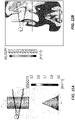
- These issues are illustrated in the diagrams shown in
FIGS. 11A and 11B . As shown in the flow direction and velocity diagram onFIG. 11A , in some areas, the flow of the flow becomes uneven and turbulent as it flows downward. This turbulent and uneven flow may result in the transport of oil carrying small bubbles toward the bottom of the compact flotation unit. The velocity contour diagram inFIG. 11B better illustrates the greater velocities in these zones of turbulent and uneven flow. - Due to ever tightening environmental regulations in some areas, newer compact flotation units able to remove at least some of these gas bubbles, and thus further reduce the amount of oil removed from water, are desirable.
-
DE 10230881 describes a water separator for air conditioning units having a separating chamber located around a housing for the collection of water deposited on the inner wall of the housing and running into a separating sump. At least one opening is provided in the housing for the separating chamber. The separator has air guiding channels which have a cross section which varies over their length, and may be divergent, convergent, divergent-convergent or convergent-divergent. The air guiding channels are spiral in design and the windings which form them are broken and so form several deflection steps.EP 0140402 describes an arrangement for the separation of particles from a gas stream comprising a substantially cylindrical vessel with an inlet attached tangentially at one end, an outlet and a guiding element extending helically from the inlet end of the vessel between the inlet and outlet to guide the gas stream with simultaneous separation of particles suspended in the gas stream. A collar is arranged between the guiding element and the outlet defining a gap-like passage along the wall of the vessel.EP 2353687 describes an inspection chamber for use in an underground water discharge system, the inspection chamber comprising first and second outlet openings for connection to the water discharge system, first and second compartments, an inner shaft, which communicates with the first and second compartments and the first outlet opening, and a sedimentation channel spiraling around the inner shaft and communicating with the second compartment and the second outlet opening.US 5403473 describes an apparatus for mixing a gas, such as ozone, with a liquid, which comprises a stacked series of round tray sections, each of which includes outer and inner helical sections and a central tube section so that the stack has continuous outer and inner helical conduits and a central column. A port at the bottom directs liquid into the outer helix, along which the liquid flows helically to the top of the column, where a crossover port directs the liquid into the inner helix so that the liquid flows helically downward to a generally cylindrical sump. The liquid stream exiting the inner helix is angled so as to create a rotating vortex in the sump, driving heavy entrained particles toward the outer walls and gas bubbles and buoyant particles toward the center of the sump. The heavy particles migrate downwardly to the bottom of the sump for periodic removal. The liquid from the sump passes through a vortex buster then upwardly through the central vertical column to an exit port at the top of the column.FR 2257348 - This section provides a general summary of the disclosure and is not a comprehensive disclosure of its full scope or all of its features.
- In accordance with one aspect, there is provided an apparatus as defined in
claim 1. Preferred embodiments are defined in claims 2 to 13. - In accordance with another aspect, there is provided a method as defined in claim 14.
- The drawings described herein are for illustrative purposes only of selected embodiments and not all possible implementations, and are not intended to limit the scope of the present disclosure.
-
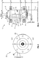
FIG. 1 is a perspective view of a compact flotation unit, in accordance with the present disclosure. -
FIG. 2 is a top view of the compact flotation unit ofFIG. 1 . -
FIG. 3 is a cross-sectional view of the compact flotation unit ofFIG. 1 , taken through the line 3-3 ofFIG. 1 . -
FIG. 4 is a cross-sectional view of the compact flotation unit ofFIG. 1 , taken through the line 4-4 ofFIG. 2 . -
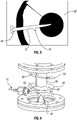
FIG. 5 is a bottom view of an inner cylinder of the compact flotation unit ofFIG. 1 . -
FIG. 6 is a perspective view of an inner cylinder of the compact flotation unit ofFIG. 1 . -
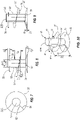
FIG. 7 is a top view of the second guide vane of the compact flotation unit ofFIG. 1 . -
FIG. 8 is an elevational view of the inner cylinder, first guide vane, and second guide vane of the compact flotation unit ofFIG. 1 . -
FIG. 9 is a perspective view of the inner cylinder, first guide vane, and second guide vane of the compact flotation unit ofFIG. 1 . -
FIG. 10 is another perspective view of the inner cylinder, first guide vane, and second guide vane of the compact flotation unit ofFIG. 1 . -
FIG. 11A is a flow direction and velocity diagram illustrating fluid flow in prior compact flotation units. -
FIG. 11B is a velocity contour diagram illustrating fluid flow in prior compact flotation units. - Corresponding reference numerals indicate corresponding parts throughout the several views of the drawings.
- Example embodiments will now be described more fully with reference to the accompanying drawings. Such example embodiments are provided so that this disclosure will be thorough, and will fully convey the scope to those who are skilled in the art. Numerous specific details are set forth such as examples of specific components, devices, and methods, to provide a thorough understanding of embodiments of the present disclosure. It will be apparent to those skilled in the art that specific details need not be employed, that example embodiments may be embodied in many different forms and that neither should be construed to limit the scope of the disclosure. In some example embodiments, well-known processes, well-known device structures, and well-known technologies are not described in detail.
- The terminology used herein is for the purpose of describing particular example embodiments only and is not intended to be limiting. As used herein, the singular forms "a," "an," and "the" may be intended to include the plural forms as well, unless the context clearly indicates otherwise. The terms "comprises," "comprising," "including," and "having," are inclusive and therefore specify the presence of stated features, integers, steps, operations, elements, and/or components, but do not preclude the presence or addition of one or more other features, integers, steps, operations, elements, components, and/or groups thereof. The method steps, processes, and operations described herein are not to be construed as necessarily requiring their performance in the particular order discussed or illustrated, unless specifically identified as an order of performance.
- It is also to be understood that additional or alternative steps may be employed.
- Although the terms first, second, third, etc. may be used herein to describe various elements, components, regions, layers and/or sections, these elements, components, regions, layers and/or sections should not be limited by these terms. These terms may be used to distinguish one element, component, region, layer or section from another region, layer or section. Terms such as "first," "second," and other numerical terms when used herein do not imply a sequence or order unless clearly indicated by the context. Thus, a first element, component, region, layer or section discussed below could be termed a second element, component, region, layer or section without departing from the teachings of the example embodiments.
- Spatially relative terms, such as "inner," "outer," "beneath," "below," "lower," "above," "upper," and the like, may be used herein for ease of description to describe one element or feature's relationship to another element(s) or feature(s) as illustrated in the figures. Spatially relative terms may be intended to encompass different orientations of the device in use or operation in addition to the orientation depicted in the figures.
- With general reference to
FIGS. 1-4 , a compact flotation unit constructed in accordance with the present teachings is illustrated and generally identified atreference numeral 10. Thecompact flotation unit 10 may be used to process and separate a mixture that includes oil, water, and gas. In this regard, thecompact flotation unit 10 may have various sizes such that thecompact flotation unit 10 can process mixture flow rates ranging from about one cubic meters per hour to about one thousand one hundred fifty cubic meters per hour. - The
compact flotation unit 10 includes a housing ortank 12 and adischarge tube 16. Thetank 12 is generally cylindrically shaped, including first and second axial ends 26, 28, and defining achamber 30 therein. It will be appreciated that thetank 12 may include other shapes outside the scope of the present teachings. - As illustrated, the first
axial end 26 of thetank 12 includes abase portion 32 and afirst outlet 34. Thebase portion 32 and thefirst outlet 34 may extend in a first axial direction from the firstaxial end 26 of thetank 12. In one configuration, thefirst outlet 34 is a water outlet in fluid communication with thechamber 30. In this regard, thefirst outlet 34 is generally operable to discharge water from thechamber 30. It will also be appreciated that thefirst outlet 34 may be operable to discharge other materials from thechamber 30. Thetank 12 may include adischarge assembly 36 including abase 38 and adeflector plate 40. Thedischarge assembly 36 may be mounted within thechamber 30 of thetank 12. The base 38 may be cylindrically shaped and disposed adjacent the firstaxial end 26 of thetank 12. The base 38 may define a plurality of radially extendingapertures 42 in fluid communication with thefirst outlet 34. Thedeflector plate 40 may be conically shaped. The base of thedeflector plate 40 may be disposed adjacent to thebase 38 of thedischarge assembly 36. - The second
axial end 28 of thetank 12 includes asecond outlet 44. Thesecond outlet 44 may extend in a second axial direction (opposite the first axial direction) from the secondaxial end 28. In one configuration, thesecond outlet 44 is an oil and gas outlet in fluid communication with thechamber 30. In this regard, thesecond outlet 44 is generally operable to discharge oil and gas from thechamber 30. It will also be appreciated that thesecond outlet 44 may be operable to discharge other materials from thechamber 30. It will also be appreciated that thesecond outlet 44 can be at any suitable location of thetank 12, and can have wall-through and vessel exits may have different mechanical designs. - The
tank 12 includes aninlet 46 and anoutlet 48. Theinlet 46 is a radially extending aperture in the sidewall of thetank 12. In one configuration, theinlet 46 is an oil, gas and water inlet in fluid communication with thechamber 30. In this regard, theinlet 46 is generally operable to dispense an oil, gas and water mixture into thechamber 30. Theoutlet 48 is a radially extending aperture in the sidewall of thetank 12. It will also be appreciated that theoutlet 48 may have other locations and configurations outside the scope of the present disclosure. In one configuration, theoutlet 48 is an oil and gas outlet in fluid communication with thedischarge tube 16. In this regard, thethird outlet 48 is generally operable to discharge oil and gas from thechamber 30. As illustrated, in one configuration, theinlet 46 is located axially above (relative to the view inFIG. 1 ) theoutlet 48. - The particular reference to
FIGS. 3 and4 , the separation assembly 14 is disposed within thechamber 30 of thetank 12. The separation assembly 14 includes aninner cylinder 50,first guide vane 54, asecond guide vane 56, and a plurality ofsupport arms 58. As illustrated, theinner cylinder 50 is substantially coaxially located within thetank 12. Theinner cylinder 50 extends along its axis 190 (shown inFIG. 10 ) between first and second axial ends 52a, 52b, defining aninner chamber 53. The first axial end 52a may be generally open and face the firstaxial end 26 of thetank 12. The second axial end 52b may be closed and face the secondaxial end 28 of the tank. In this regard, the second axial end 52b of theinner cylinder 50 may include a substantiallycircular portion 60 generally sealing the second axial end of the inner cylinder (shown inFIG 11 ). Closing the second axial end 52b of theinner cylinder 50 helps to prevent the flow of water or other fluid in the first axial direction within theinner chamber 53 of theinner cylinder 50, and also allows for the formation of a gas bubble or air pocket within theinner chamber 53 adjacent to the second axial end 52b of theinner cylinder 50. - The
first guide vane 54 extends helically and coaxially about the outer periphery of theinner cylinder 50, defining a radially extendinggap 56 between theguide vane 54 and theinner cylinder 50. In one configuration, thefirst guide vane 54 extends approximately three hundred sixty degrees about theinner cylinder 50. It will be appreciated, however, that thefirst guide vane 54 may extend any number of revolutions, or fractions thereof, about the outer periphery of theinner cylinder 50 within the scope of the present teachings. Referring additionally toFIG. 8 , thefirst guide vane 54 may include a substantiallyplanar surface 59 defining an angle α with the radius of theinner cylinder 50. In one configuration, the angle α is approximately seven and one-tenth degrees, such that thesurface 59 slopes radially inward relative to the inner cylinder 50 (i.e., the angle α is seven and one-tenth degrees above a line defined by the radius of theinner cylinder 50, relative to the view inFIG. 1 ). It will be appreciated, however, that the angle α may have other values within the scope of the present teachings. With particular reference toFIG. 4 , theinlet 46 may be located in thetank 12 such that theinlet 46 is axially aligned with a portion of thefirst guide vane 54. Accordingly, fluid entering thetank 12 in the radial direction through theinlet 46 may define an angle σ with theplanar surface 59 of thefirst guide vane 54. The angle σ may be substantially equal to the angle α, such that the flow of fluid through thecompact flotation unit 10 is smooth and/or generally laminar, thus providing enhanced separation of the oil, water, and/or gas. - The
second guide vane 56 extends coaxially about the outer periphery of theinner cylinder 50, and may urge the fluid in thechamber 30 to orbit about the outer periphery of theinner cylinder 50. As illustrated inFIG. 4 , thesecond guide vane 56 may be located axially below thefirst guide vane 54, such that the second guide vane is located substantially adjacent to the first axial end 52a of theinner cylinder 50. In one configuration, thesecond guide vane 56 extends approximately three hundred sixty degrees about the outer periphery of theinner cylinder 50. It will be appreciated, however, that thesecond guide vane 56 may extend less than three hundred sixty degrees about the outer periphery of theinner cylinder 50, such that first and second ends 62, 64 of theguide vane 56 define a gap therebetween. Thesecond guide vane 56 may include a substantiallyplanar surface 60 defining an angle β with the radius of theinner cylinder 50, as also shown inFIG. 8 . Theplanar surface 60 may be adjacent to the outer periphery of theinner cylinder 50. In one configuration, the angle β is approximately fifteen degrees, such that thesurface 60 slopes radially outward relative to the inner cylinder 50 (i.e., the angle β is fifteen degrees below a line defined by the radius of theinner cylinder 50, relative to the view inFIG. 1 ). It will be appreciated, however, that the angle β may have other values within the scope of the present teachings. - Referring to
FIG. 6 for illustration purposes, in some embodiments, the first and second ends, 62 and 64, may overlap. In some other embodiments the first and second ends, 62 and 64, may be orientated in such way that there exists a gap between the first and second ends, 62 and 64, from both an axially extending and circumferentially extending perspective; while in yet other embodiments, the first and second ends, 62 and 64, are aligned from a circumferentially perspective, while there exists an axial gap (such as that shown inFIG. 9 as D1, with the circumferential alignment being shown inFIG. 7 ). - As illustrated in
FIGS. 9 and11 , thesecond guide vane 56 may extend about the periphery of theinner cylinder 50 in a helical configuration, including any number of revolutions, or fractions thereof, within the scope of the present teachings. In one configuration, the helical configuration of thesecond guide vane 56 may extend about the outer periphery of the inner cylinder approximately three hundred sixty degrees. The pitch of thesecond guide vane 56 may be such that thefirst end 62 ofsecond guide vane 56 is separated or axially offset from thesecond end 64 of thesecond guide vane 56 by an axially extending distance D1. In one configuration, the distance D1 may be approximately one centimeter. It will be appreciated, however, that the distance D1 may be more than or less than one centimeter. For example, the distance D1 may be equal or greater than about one tenth of a centimeter and less than about forty centimeters (or any point within this range). The distance D1 separating thefirst end 62 from thesecond end 64 may help gas bubbles and oil droplets contained in the fluid within thechamber 30 to move in the second axial direction within thechamber 53 of theinner cylinder 50. Indeed, thesecond guide vane 56 may be movably coupled to theinner cylinder 50, and the distance D1, or gap, between thefirst end 62 andsecond end 64 may mechanically adjust based upon a fluid flow rate through the gap. For example, the distance D1 may increase as the fluid flow rate increases. The shape of the gap between thefirst end 62 andsecond end 64 may take any suitable shape, such as a rectangular shape, circular shape, quadratic shape, or a pipe rack shape. - The configuration of the first and
second guide vanes inlet 46. In one stage of the method, the mixture may contact and follow thesurface 59 of thefirst guide vane 54. In another stage of the method, the mixture may contact and follow thesurface 60 of thesecond guide vane 56, before entering theinner cylinder 50 between the first and second ends 62, 64 of the second guide vane. Indeed, the size and shape of thefirst guide vane 54,second guide vane 56, andinner cylinder 50 may be such that gas bubbles and oil drops entering the inner cylinder have a co-current flow with water toward thedischarge tube 16. - The
support arms 58 may generally extend radially between thetank 12 and theinner cylinder 50 to secure and support theinner cylinder 50 within thetank 12. In one configuration, threesupport arms 58 extend from the second axial end 52b of theinner cylinder 50. It will be appreciated, however, that theinner cylinder 50 may include other numbers and configurations ofsupport arms 58 within the scope of the present teachings. - In
FIG. 3 , thedischarge tube 16 extends between afirst end 66 and asecond end 68. Thefirst end 66 is in fluid communication with thethird outlet 48. As illustrated, although not limited thereto, thedischarge tube 16 may be substantially L-shaped, including afirst portion 70 and asecond portion 72; however any suitable shape of the discharge tube may be used. Thefirst portion 70 may extend in the axial direction within thechamber 53 of theinner cylinder 50, such that thesecond end 68 of thedischarge tube 16 is disposed within, and in fluid communication with, the upper one-half of the inner cylinder 50 (relative to the view inFIG. 3 ). In one configuration, thesecond end 68 of thedischarge tube 16 is substantially adjacent to the second axial end 52b of theinner cylinder 50. Locating thesecond end 68 of thedischarge tube 16 substantially adjacent to the second axial end 52b of theinner cylinder 50 helps to ensure that thesecond end 68 is in fluid communication with the gas bubble or air pocket formed within thechamber 53. The joint between thefirst end 66 andsecond end 68 of thedischarge tube 16 may be radially centered with respect to thesecond guide vane 56, as shown inFIG. 5 , or may instead be adjacent the wall of thecylinder 50, as shown inFIG. 6 . Referring again toFIG. 3 , it will appreciated that thedischarge tube 16 may have other shapes and configurations within the scope of the present disclosure, such that thefirst end 66 is in fluid communication with thethird outlet 48 and the second end is substantially adjacent to the second axial end 52b of theinner cylinder 50. - Further, as shown in
Figures 1-3 , thetank 12 may be assembled using radially extending flanges. However, any suitable construction technique, or feature, may be used to form thetank 12, including, but not limited to, a single contiguous sealed vessel formed by welding the first and second axial ends 26 and 28, to the cylindrical shape. - The foregoing description of the embodiments has been provided for purposes of illustration and description. It is not intended to be exhaustive or to limit the disclosure. Individual elements or features of a particular embodiment are generally not limited to that particular embodiment, but, where applicable, are interchangeable and can be used in a selected embodiment, even if not specifically shown or described. The invention is defined by the appended independent claims. Any information falling outside the scope of the claims is for explanation only.
Claims (14)
- An apparatus comprising:a cylindrical tank (12) having a fluid inlet (46) extending radially in the sidewall of the tank (12) and a fluid outlet (48);a cylinder (50) disposed within and coaxial with the tank (12) and having a closed end (52b) and an open end (52a), the open end (52a) facing a bottom (26) of the tank (12);a first guide vane (54) disposed about the cylinder (50), the first guide vane (54) having a portion axially aligned with the fluid inlet (46);a second guide vane (56) extending coaxially about an outer periphery of the cylinder (50) adjacent the open end (52a) thereof and including a first end (62) and a second end (64), the first end (62) of the second guide vane (56) being axially offset from the second end (64) of the second guide vane (56); anda discharge tube (16) at least partially disposed within the cylinder (50) and in fluid communication with the fluid outlet (48).
- The apparatus of claim 1, wherein the first and second guide vanes (54, 56) are helical in shape and wherein the first guide vane (54) has a helical pitch greater than a helical pitch of the second guide vane (56).
- The apparatus of claim 1, wherein the first and second guide vanes (54, 56) are helical in shape and extend an equal amount outwardly from the cylinder (50).
- The apparatus of claim 1, wherein the first guide vane (54) extends coaxially about an outer periphery of the cylinder (50), defining a radially extending gap between the first guide vane (54) and the cylinder (50).
- The apparatus of claim 1, wherein the first guide vane (54) has a substantially planar surface (59) defining an angle with respect to a radius of the cylinder (50).
- The apparatus of claim 5, wherein the fluid inlet (46) is shaped such that fluid entering the tank (12) therethrough defines an angle with respect to the substantially planar surface (59) of the first guide vane (54) that is substantially equal to the angle defined by the substantially planar surface (59) with respect to the radius of the cylinder (50).
- The apparatus claim 1, wherein the second guide vane (56) extends circumferentially around the cylinder by more than 360 degrees such that the first end and second ends (62, 64) overlap.
- The apparatus claim 1, wherein the second guide vane (56) extends around the cylinder (50) in a helical configuration such that first end (62) defines an axial and circumferential gap with respect to the second end (64) of the second guide vane (56).
- The apparatus of claim 1, wherein the second guide vane (56) has a substantially planar surface (60) defining an angle with respect to a radius of the cylinder (50) such that the substantially planar surface (60) slopes radially outwardly relative to the cylinder (50).
- The apparatus of claim 1, wherein the cylinder (50) is disposed within the tank (12) such that the closed end (52b) thereof is adjacent to, and spaced apart from, a top of the tank (12).
- The apparatus of claim 1, wherein the first guide vane (54), the second guide vane (56), and the cylinder (50) are shaped and disposed with respect to each other such that gas bubbles and oil drops entering the cylinder (12) have a co-current flow with water toward the discharge tube (16).
- The apparatus of claim 1, wherein the second guide vane (56) is movably coupled to the cylinder (50) and wherein the axial offset between the first end (62) of the second guide vane (56) and the second end (64) of the second guide vane (56) defines a gap that adjusts based upon a rate of flow of fluid therethrough.
- The apparatus of any of the preceding claims, wherein the apparatus is a flotation unit (10).
- A method comprising:
accepting flow of a mixture comprising water, a hydrocarbon containing liquid not miscible with the water, and a gas through a pipeline;separating the hydrocarbon containing liquid and the gas from the water by feeding the mixture through the apparatus (10) of any preceding claim wherein the fluid inlet (46) of the tank (12) is in fluid communication with the pipeline; andexpelling at least one of a portion of the gas and the hydrocarbon containing liquid from the cylinder (50) through the discharge tube (16).
Applications Claiming Priority (2)
| Application Number | Priority Date | Filing Date | Title |
|---|---|---|---|
| US201361911886P | 2013-12-04 | 2013-12-04 | |
| PCT/US2014/068478 WO2015085023A1 (en) | 2013-12-04 | 2014-12-04 | Compact flotation unit having multiple vanes disposed around a cylinder used for waste collection |
Publications (3)
| Publication Number | Publication Date |
|---|---|
| EP3089801A1 EP3089801A1 (en) | 2016-11-09 |
| EP3089801A4 EP3089801A4 (en) | 2017-08-02 |
| EP3089801B1 true EP3089801B1 (en) | 2022-07-20 |
Family
ID=53274102
Family Applications (1)
| Application Number | Title | Priority Date | Filing Date |
|---|---|---|---|
| EP14867374.2A Active EP3089801B1 (en) | 2013-12-04 | 2014-12-04 | Compact flotation unit having multiple vanes disposed around a cylinder used for waste collection |
Country Status (5)
| Country | Link |
|---|---|
| US (1) | US10343086B2 (en) |
| EP (1) | EP3089801B1 (en) |
| DK (1) | DK3089801T3 (en) |
| SG (1) | SG11201604436WA (en) |
| WO (1) | WO2015085023A1 (en) |
Families Citing this family (5)
| Publication number | Priority date | Publication date | Assignee | Title |
|---|---|---|---|---|
| CN107913632B (en) * | 2016-10-10 | 2023-07-11 | 中国石油化工股份有限公司 | Ternary mixing device |
| CN106865673A (en) * | 2017-04-13 | 2017-06-20 | 中国石油大学(华东) | A kind of swirl flow air supporting oil-contained waste water treatment device |
| CN107473306A (en) * | 2017-08-25 | 2017-12-15 | 中海油能源发展股份有限公司 | A kind of adjustable single tank twin-stage cyclone air-flotation device of stabilizing feed well |
| CN110980983A (en) * | 2019-11-13 | 2020-04-10 | 江苏亚洲环保有限公司 | Vertical flow type solid-liquid separator |
| CN117023690B (en) * | 2023-08-18 | 2024-01-19 | 北京石油化工学院 | A vertical cyclone flotation equipment that enhances the shallow settlement of spiral fins by air lifting |
Family Cites Families (23)
| Publication number | Priority date | Publication date | Assignee | Title |
|---|---|---|---|---|
| US1565318A (en) | 1925-04-06 | 1925-12-15 | Ernest F Fisher | Separator |
| US1940762A (en) * | 1932-08-15 | 1933-12-26 | Petroleum Rectifying Co California | Separator for treated emulsions |
| DE705339C (en) | 1937-08-22 | 1941-04-26 | Hedwig Schwabach Geb Lorenz | Centrifugal dust separator |
| US2509172A (en) * | 1946-05-20 | 1950-05-23 | Konrad F Schreier | Fractionating column or the like |
| NL177187C (en) * | 1974-01-16 | 1985-08-16 | Nederlandse Gasunie Nv | DEVICE FOR SEPARATING POLLUTANTS FROM GASES. |
| SE440978B (en) * | 1983-08-25 | 1985-09-02 | Tetra Pak Int | DEVICE FOR SEPARATION OF GAS PARTICULARS, SPECIFICALLY IN THE MANUFACTURE OF ASEPTIC PACKAGING CONTAINERS |
| NL8902978A (en) * | 1989-12-02 | 1991-07-01 | Nederlandse Gasunie Nv | DEVICE FOR SEPARATING LIQUIDS AND / OR SOLIDS FROM A GAS FLOW. |
| US5403486A (en) * | 1991-12-31 | 1995-04-04 | Baker Hughes Incorporated | Accelerator system in a centrifuge |
| US5403473A (en) | 1994-02-15 | 1995-04-04 | Automatic Control Technology, Inc. | Apparatus for mixing gases and liquids and separating solids using a vortex |
| AUPM714794A0 (en) * | 1994-07-29 | 1994-08-18 | International Fluid Separation Pty Limited | Separation apparatus and method |
| EP1208897A1 (en) | 2000-11-21 | 2002-05-29 | Epcon Norge AS | Combined degassing and flotation tank |
| DE10230881A1 (en) | 2002-07-09 | 2004-02-26 | Liebherr-Aerospace Lindenberg Gmbh | Water separator for air conditioning units in especially aircraft has separating chamber located around housing for collecting of water deposited on inner wall of housing and running into separating sump |
| GB2401564A (en) * | 2003-05-15 | 2004-11-17 | Mann & Hummel Gmbh | Centrifugal separation apparatus and rotor |
| EA011658B1 (en) * | 2004-01-20 | 2009-04-28 | М-И Эпкон Ас | Initial separation of fluid at well head |
| EP1783101A1 (en) * | 2005-11-03 | 2007-05-09 | M-I Epcon As | Method and plant for purifying water |
| EP1782870A1 (en) | 2005-10-28 | 2007-05-09 | M-I Epcon As | A separator tank |
| RU2379119C1 (en) | 2008-11-10 | 2010-01-20 | Государственное образовательное учреждение высшего профессионального образования "Московский государственный университет инженерной экологии" | Centrifugal separator |
| US7867310B2 (en) | 2009-01-29 | 2011-01-11 | General Electric Company | Method and apparatus for separating air and oil |
| EP2263768A1 (en) * | 2009-06-17 | 2010-12-22 | M-I Epcon As | A separator tank for separating oil and gas from water |
| EP2263766A1 (en) * | 2009-06-17 | 2010-12-22 | M-I Epcon As | A separator tank for separating oil and gas from water |
| NL1037680C2 (en) | 2010-02-03 | 2011-08-04 | Wavin Bv | Inspection chamber with filter. |
| DK177387B1 (en) * | 2010-04-12 | 2013-03-04 | Schlumberger Norge As | A flotation unit for purifying water, such as a CFU (Compact Flotation Unit) |
| WO2013043354A1 (en) * | 2011-09-21 | 2013-03-28 | Exxonmobil Upstream Research Company | Separating oil and water streams |
-
2014
- 2014-12-04 SG SG11201604436WA patent/SG11201604436WA/en unknown
- 2014-12-04 US US15/101,194 patent/US10343086B2/en active Active
- 2014-12-04 DK DK14867374.2T patent/DK3089801T3/en active
- 2014-12-04 EP EP14867374.2A patent/EP3089801B1/en active Active
- 2014-12-04 WO PCT/US2014/068478 patent/WO2015085023A1/en not_active Ceased
Also Published As
| Publication number | Publication date |
|---|---|
| US10343086B2 (en) | 2019-07-09 |
| WO2015085023A1 (en) | 2015-06-11 |
| US20160303492A1 (en) | 2016-10-20 |
| EP3089801A4 (en) | 2017-08-02 |
| DK3089801T3 (en) | 2022-10-24 |
| EP3089801A1 (en) | 2016-11-09 |
| SG11201604436WA (en) | 2016-07-28 |
Similar Documents
| Publication | Publication Date | Title |
|---|---|---|
| US10518195B2 (en) | Inlet diverter | |
| US9427689B2 (en) | Uniflow centrifugal gas-liquid separator | |
| US11673074B2 (en) | Cyclonic inlet diverter | |
| CA2578262C (en) | Rotary separator and method | |
| CN102725070A (en) | Separation plant with gravity pre-separator followed by centrifugal separator | |
| US10343086B2 (en) | Compact flotation unit having multiple vanes disposed around a cylinder used for waste collection | |
| US10207278B2 (en) | Centrifugal fluid/particulate separator | |
| JPH10128023A (en) | Gas transfer piping | |
| CN109310932B (en) | Hydrocarbon-Water Separator | |
| EP2789396A1 (en) | Vortex separator and separation method | |
| US10617991B2 (en) | Low dispersion gas-liquid separator | |
| CN101537321B (en) | Vertical-type gas-liquid two-phase fluid mixing flow stabilizer | |
| CN114555205A (en) | Separating device with plug-in | |
| EP2908922B1 (en) | Two stage in-line separator | |
| RU2618708C1 (en) | Cyclone for purifying gas flow of liquid phase droplets | |
| EP2946836A1 (en) | A centrifugal separator | |
| US11850605B2 (en) | Apparatus and method to separate and condition multiphase flow | |
| WO2007067073A1 (en) | Method and apparatus for separating submerged particles from a fluid. | |
| RU2454266C1 (en) | Vortex-type gas separator (versions) | |
| RU157602U1 (en) | RECEPTION SEPARATOR FOR INSTALLATION OF INTEGRATED GAS PREPARATION | |
| KR20110008097A (en) | Multiphase flow splitting method and apparatus | |
| EP3875163A1 (en) | Separator for a gaseous fluid | |
| RU2064326C1 (en) | Separator | |
| US10612326B2 (en) | Shale-gas separator discharge diffuser | |
| GB2503261A (en) | Inlet device |
Legal Events
| Date | Code | Title | Description |
|---|---|---|---|
| PUAI | Public reference made under article 153(3) epc to a published international application that has entered the european phase |
Free format text: ORIGINAL CODE: 0009012 |
|
| 17P | Request for examination filed |
Effective date: 20160602 |
|
| AK | Designated contracting states |
Kind code of ref document: A1 Designated state(s): AL AT BE BG CH CY CZ DE DK EE ES FI FR GB GR HR HU IE IS IT LI LT LU LV MC MK MT NL NO PL PT RO RS SE SI SK SM TR |
|
| AX | Request for extension of the european patent |
Extension state: BA ME |
|
| DAX | Request for extension of the european patent (deleted) | ||
| A4 | Supplementary search report drawn up and despatched |
Effective date: 20170704 |
|
| RIC1 | Information provided on ipc code assigned before grant |
Ipc: C02F 1/40 20060101ALI20170628BHEP Ipc: B01D 17/035 20060101AFI20170628BHEP Ipc: B01D 17/02 20060101ALI20170628BHEP Ipc: C02F 101/32 20060101ALI20170628BHEP |
|
| STAA | Information on the status of an ep patent application or granted ep patent |
Free format text: STATUS: EXAMINATION IS IN PROGRESS |
|
| 17Q | First examination report despatched |
Effective date: 20201118 |
|
| REG | Reference to a national code |
Ref country code: DE Ref legal event code: R079 Ref document number: 602014084363 Country of ref document: DE Free format text: PREVIOUS MAIN CLASS: B01D0017035000 Ipc: B03D0001140000 |
|
| GRAP | Despatch of communication of intention to grant a patent |
Free format text: ORIGINAL CODE: EPIDOSNIGR1 |
|
| STAA | Information on the status of an ep patent application or granted ep patent |
Free format text: STATUS: GRANT OF PATENT IS INTENDED |
|
| RIC1 | Information provided on ipc code assigned before grant |
Ipc: B01D 17/02 20060101ALI20220131BHEP Ipc: B04C 5/13 20060101ALI20220131BHEP Ipc: B04C 5/103 20060101ALI20220131BHEP Ipc: B03D 1/24 20060101ALI20220131BHEP Ipc: B03D 1/14 20060101AFI20220131BHEP |
|
| INTG | Intention to grant announced |
Effective date: 20220215 |
|
| RIN1 | Information on inventor provided before grant (corrected) |
Inventor name: HARDLI, LARS Inventor name: MAELUM, MICHEL IVER TVEITAN Inventor name: RABE, KARSTEN |
|
| GRAS | Grant fee paid |
Free format text: ORIGINAL CODE: EPIDOSNIGR3 |
|
| GRAA | (expected) grant |
Free format text: ORIGINAL CODE: 0009210 |
|
| STAA | Information on the status of an ep patent application or granted ep patent |
Free format text: STATUS: THE PATENT HAS BEEN GRANTED |
|
| AK | Designated contracting states |
Kind code of ref document: B1 Designated state(s): AL AT BE BG CH CY CZ DE DK EE ES FI FR GB GR HR HU IE IS IT LI LT LU LV MC MK MT NL NO PL PT RO RS SE SI SK SM TR |
|
| REG | Reference to a national code |
Ref country code: GB Ref legal event code: FG4D |
|
| REG | Reference to a national code |
Ref country code: CH Ref legal event code: EP |
|
| REG | Reference to a national code |
Ref country code: DE Ref legal event code: R096 Ref document number: 602014084363 Country of ref document: DE |
|
| REG | Reference to a national code |
Ref country code: AT Ref legal event code: REF Ref document number: 1505186 Country of ref document: AT Kind code of ref document: T Effective date: 20220815 |
|
| REG | Reference to a national code |
Ref country code: IE Ref legal event code: FG4D |
|
| REG | Reference to a national code |
Ref country code: DK Ref legal event code: T3 Effective date: 20221021 |
|
| REG | Reference to a national code |
Ref country code: LT Ref legal event code: MG9D |
|
| REG | Reference to a national code |
Ref country code: NL Ref legal event code: MP Effective date: 20220720 |
|
| REG | Reference to a national code |
Ref country code: NO Ref legal event code: T2 Effective date: 20220720 |
|
| PG25 | Lapsed in a contracting state [announced via postgrant information from national office to epo] |
Ref country code: SE Free format text: LAPSE BECAUSE OF FAILURE TO SUBMIT A TRANSLATION OF THE DESCRIPTION OR TO PAY THE FEE WITHIN THE PRESCRIBED TIME-LIMIT Effective date: 20220720 Ref country code: RS Free format text: LAPSE BECAUSE OF FAILURE TO SUBMIT A TRANSLATION OF THE DESCRIPTION OR TO PAY THE FEE WITHIN THE PRESCRIBED TIME-LIMIT Effective date: 20220720 Ref country code: PT Free format text: LAPSE BECAUSE OF FAILURE TO SUBMIT A TRANSLATION OF THE DESCRIPTION OR TO PAY THE FEE WITHIN THE PRESCRIBED TIME-LIMIT Effective date: 20221121 Ref country code: NL Free format text: LAPSE BECAUSE OF FAILURE TO SUBMIT A TRANSLATION OF THE DESCRIPTION OR TO PAY THE FEE WITHIN THE PRESCRIBED TIME-LIMIT Effective date: 20220720 Ref country code: LV Free format text: LAPSE BECAUSE OF FAILURE TO SUBMIT A TRANSLATION OF THE DESCRIPTION OR TO PAY THE FEE WITHIN THE PRESCRIBED TIME-LIMIT Effective date: 20220720 Ref country code: LT Free format text: LAPSE BECAUSE OF FAILURE TO SUBMIT A TRANSLATION OF THE DESCRIPTION OR TO PAY THE FEE WITHIN THE PRESCRIBED TIME-LIMIT Effective date: 20220720 Ref country code: FI Free format text: LAPSE BECAUSE OF FAILURE TO SUBMIT A TRANSLATION OF THE DESCRIPTION OR TO PAY THE FEE WITHIN THE PRESCRIBED TIME-LIMIT Effective date: 20220720 Ref country code: ES Free format text: LAPSE BECAUSE OF FAILURE TO SUBMIT A TRANSLATION OF THE DESCRIPTION OR TO PAY THE FEE WITHIN THE PRESCRIBED TIME-LIMIT Effective date: 20220720 |
|
| REG | Reference to a national code |
Ref country code: AT Ref legal event code: MK05 Ref document number: 1505186 Country of ref document: AT Kind code of ref document: T Effective date: 20220720 |
|
| PG25 | Lapsed in a contracting state [announced via postgrant information from national office to epo] |
Ref country code: PL Free format text: LAPSE BECAUSE OF FAILURE TO SUBMIT A TRANSLATION OF THE DESCRIPTION OR TO PAY THE FEE WITHIN THE PRESCRIBED TIME-LIMIT Effective date: 20220720 Ref country code: IS Free format text: LAPSE BECAUSE OF FAILURE TO SUBMIT A TRANSLATION OF THE DESCRIPTION OR TO PAY THE FEE WITHIN THE PRESCRIBED TIME-LIMIT Effective date: 20221120 Ref country code: HR Free format text: LAPSE BECAUSE OF FAILURE TO SUBMIT A TRANSLATION OF THE DESCRIPTION OR TO PAY THE FEE WITHIN THE PRESCRIBED TIME-LIMIT Effective date: 20220720 Ref country code: GR Free format text: LAPSE BECAUSE OF FAILURE TO SUBMIT A TRANSLATION OF THE DESCRIPTION OR TO PAY THE FEE WITHIN THE PRESCRIBED TIME-LIMIT Effective date: 20221021 |
|
| REG | Reference to a national code |
Ref country code: DE Ref legal event code: R097 Ref document number: 602014084363 Country of ref document: DE |
|
| PG25 | Lapsed in a contracting state [announced via postgrant information from national office to epo] |
Ref country code: SM Free format text: LAPSE BECAUSE OF FAILURE TO SUBMIT A TRANSLATION OF THE DESCRIPTION OR TO PAY THE FEE WITHIN THE PRESCRIBED TIME-LIMIT Effective date: 20220720 Ref country code: RO Free format text: LAPSE BECAUSE OF FAILURE TO SUBMIT A TRANSLATION OF THE DESCRIPTION OR TO PAY THE FEE WITHIN THE PRESCRIBED TIME-LIMIT Effective date: 20220720 Ref country code: CZ Free format text: LAPSE BECAUSE OF FAILURE TO SUBMIT A TRANSLATION OF THE DESCRIPTION OR TO PAY THE FEE WITHIN THE PRESCRIBED TIME-LIMIT Effective date: 20220720 Ref country code: AT Free format text: LAPSE BECAUSE OF FAILURE TO SUBMIT A TRANSLATION OF THE DESCRIPTION OR TO PAY THE FEE WITHIN THE PRESCRIBED TIME-LIMIT Effective date: 20220720 |
|
| PLBE | No opposition filed within time limit |
Free format text: ORIGINAL CODE: 0009261 |
|
| STAA | Information on the status of an ep patent application or granted ep patent |
Free format text: STATUS: NO OPPOSITION FILED WITHIN TIME LIMIT |
|
| PG25 | Lapsed in a contracting state [announced via postgrant information from national office to epo] |
Ref country code: SK Free format text: LAPSE BECAUSE OF FAILURE TO SUBMIT A TRANSLATION OF THE DESCRIPTION OR TO PAY THE FEE WITHIN THE PRESCRIBED TIME-LIMIT Effective date: 20220720 Ref country code: EE Free format text: LAPSE BECAUSE OF FAILURE TO SUBMIT A TRANSLATION OF THE DESCRIPTION OR TO PAY THE FEE WITHIN THE PRESCRIBED TIME-LIMIT Effective date: 20220720 |
|
| 26N | No opposition filed |
Effective date: 20230421 |
|
| PG25 | Lapsed in a contracting state [announced via postgrant information from national office to epo] |
Ref country code: AL Free format text: LAPSE BECAUSE OF FAILURE TO SUBMIT A TRANSLATION OF THE DESCRIPTION OR TO PAY THE FEE WITHIN THE PRESCRIBED TIME-LIMIT Effective date: 20220720 |
|
| REG | Reference to a national code |
Ref country code: DE Ref legal event code: R119 Ref document number: 602014084363 Country of ref document: DE |
|
| REG | Reference to a national code |
Ref country code: CH Ref legal event code: PL |
|
| REG | Reference to a national code |
Ref country code: BE Ref legal event code: MM Effective date: 20221231 |
|
| PG25 | Lapsed in a contracting state [announced via postgrant information from national office to epo] |
Ref country code: SI Free format text: LAPSE BECAUSE OF FAILURE TO SUBMIT A TRANSLATION OF THE DESCRIPTION OR TO PAY THE FEE WITHIN THE PRESCRIBED TIME-LIMIT Effective date: 20220720 Ref country code: LU Free format text: LAPSE BECAUSE OF NON-PAYMENT OF DUE FEES Effective date: 20221204 |
|
| PG25 | Lapsed in a contracting state [announced via postgrant information from national office to epo] |
Ref country code: LI Free format text: LAPSE BECAUSE OF NON-PAYMENT OF DUE FEES Effective date: 20221231 Ref country code: IE Free format text: LAPSE BECAUSE OF NON-PAYMENT OF DUE FEES Effective date: 20221204 Ref country code: DE Free format text: LAPSE BECAUSE OF NON-PAYMENT OF DUE FEES Effective date: 20230701 Ref country code: CH Free format text: LAPSE BECAUSE OF NON-PAYMENT OF DUE FEES Effective date: 20221231 |
|
| PG25 | Lapsed in a contracting state [announced via postgrant information from national office to epo] |
Ref country code: BE Free format text: LAPSE BECAUSE OF NON-PAYMENT OF DUE FEES Effective date: 20221231 |
|
| PG25 | Lapsed in a contracting state [announced via postgrant information from national office to epo] |
Ref country code: HU Free format text: LAPSE BECAUSE OF FAILURE TO SUBMIT A TRANSLATION OF THE DESCRIPTION OR TO PAY THE FEE WITHIN THE PRESCRIBED TIME-LIMIT; INVALID AB INITIO Effective date: 20141204 |
|
| PG25 | Lapsed in a contracting state [announced via postgrant information from national office to epo] |
Ref country code: CY Free format text: LAPSE BECAUSE OF FAILURE TO SUBMIT A TRANSLATION OF THE DESCRIPTION OR TO PAY THE FEE WITHIN THE PRESCRIBED TIME-LIMIT Effective date: 20220720 |
|
| PG25 | Lapsed in a contracting state [announced via postgrant information from national office to epo] |
Ref country code: MK Free format text: LAPSE BECAUSE OF FAILURE TO SUBMIT A TRANSLATION OF THE DESCRIPTION OR TO PAY THE FEE WITHIN THE PRESCRIBED TIME-LIMIT Effective date: 20220720 Ref country code: IT Free format text: LAPSE BECAUSE OF FAILURE TO SUBMIT A TRANSLATION OF THE DESCRIPTION OR TO PAY THE FEE WITHIN THE PRESCRIBED TIME-LIMIT Effective date: 20220720 |
|
| PG25 | Lapsed in a contracting state [announced via postgrant information from national office to epo] |
Ref country code: MC Free format text: LAPSE BECAUSE OF FAILURE TO SUBMIT A TRANSLATION OF THE DESCRIPTION OR TO PAY THE FEE WITHIN THE PRESCRIBED TIME-LIMIT Effective date: 20220720 |
|
| PG25 | Lapsed in a contracting state [announced via postgrant information from national office to epo] |
Ref country code: TR Free format text: LAPSE BECAUSE OF FAILURE TO SUBMIT A TRANSLATION OF THE DESCRIPTION OR TO PAY THE FEE WITHIN THE PRESCRIBED TIME-LIMIT Effective date: 20220720 Ref country code: MC Free format text: LAPSE BECAUSE OF FAILURE TO SUBMIT A TRANSLATION OF THE DESCRIPTION OR TO PAY THE FEE WITHIN THE PRESCRIBED TIME-LIMIT Effective date: 20220720 |
|
| PG25 | Lapsed in a contracting state [announced via postgrant information from national office to epo] |
Ref country code: BG Free format text: LAPSE BECAUSE OF FAILURE TO SUBMIT A TRANSLATION OF THE DESCRIPTION OR TO PAY THE FEE WITHIN THE PRESCRIBED TIME-LIMIT Effective date: 20220720 |
|
| PG25 | Lapsed in a contracting state [announced via postgrant information from national office to epo] |
Ref country code: MT Free format text: LAPSE BECAUSE OF FAILURE TO SUBMIT A TRANSLATION OF THE DESCRIPTION OR TO PAY THE FEE WITHIN THE PRESCRIBED TIME-LIMIT Effective date: 20220720 |
|
| PGFP | Annual fee paid to national office [announced via postgrant information from national office to epo] |
Ref country code: FR Payment date: 20250930 Year of fee payment: 12 |
|
| PGFP | Annual fee paid to national office [announced via postgrant information from national office to epo] |
Ref country code: GB Payment date: 20251001 Year of fee payment: 12 |
|
| PGFP | Annual fee paid to national office [announced via postgrant information from national office to epo] |
Ref country code: NO Payment date: 20251210 Year of fee payment: 12 |
|
| PGFP | Annual fee paid to national office [announced via postgrant information from national office to epo] |
Ref country code: DK Payment date: 20251212 Year of fee payment: 12 |