EP3089438A1 - Imminent failure indication for power sourcing equipment - Google Patents
Imminent failure indication for power sourcing equipment Download PDFInfo
- Publication number
- EP3089438A1 EP3089438A1 EP15305652.8A EP15305652A EP3089438A1 EP 3089438 A1 EP3089438 A1 EP 3089438A1 EP 15305652 A EP15305652 A EP 15305652A EP 3089438 A1 EP3089438 A1 EP 3089438A1
- Authority
- EP
- European Patent Office
- Prior art keywords
- power
- signal
- sourcing equipment
- access node
- power feeding
- Prior art date
- Legal status (The legal status is an assumption and is not a legal conclusion. Google has not performed a legal analysis and makes no representation as to the accuracy of the status listed.)
- Granted
Links
- 238000012358 sourcing Methods 0.000 title claims abstract description 23
- 238000004891 communication Methods 0.000 claims abstract description 26
- 238000001514 detection method Methods 0.000 claims abstract description 11
- 239000003990 capacitor Substances 0.000 claims description 9
- 230000011664 signaling Effects 0.000 claims description 4
- 238000000278 gas antisolvent technique Methods 0.000 description 17
- RYGMFSIKBFXOCR-UHFFFAOYSA-N Copper Chemical compound [Cu] RYGMFSIKBFXOCR-UHFFFAOYSA-N 0.000 description 5
- 229910052802 copper Inorganic materials 0.000 description 5
- 239000010949 copper Substances 0.000 description 5
- 230000001747 exhibiting effect Effects 0.000 description 4
- 239000003795 chemical substances by application Substances 0.000 description 3
- 230000003247 decreasing effect Effects 0.000 description 2
- 238000012544 monitoring process Methods 0.000 description 2
- 238000000899 pressurised-fluid extraction Methods 0.000 description 2
- 230000001105 regulatory effect Effects 0.000 description 2
- 230000007704 transition Effects 0.000 description 2
- 102100021334 Bcl-2-related protein A1 Human genes 0.000 description 1
- 102000012677 DET1 Human genes 0.000 description 1
- 101150113651 DET1 gene Proteins 0.000 description 1
- 101150066284 DET2 gene Proteins 0.000 description 1
- 102100023882 Endoribonuclease ZC3H12A Human genes 0.000 description 1
- 101710112715 Endoribonuclease ZC3H12A Proteins 0.000 description 1
- 101000677540 Homo sapiens Acetyl-CoA carboxylase 2 Proteins 0.000 description 1
- 101000894929 Homo sapiens Bcl-2-related protein A1 Proteins 0.000 description 1
- 108700012361 REG2 Proteins 0.000 description 1
- 101150108637 REG2 gene Proteins 0.000 description 1
- 101100120298 Rattus norvegicus Flot1 gene Proteins 0.000 description 1
- 101100412403 Rattus norvegicus Reg3b gene Proteins 0.000 description 1
- 239000000969 carrier Substances 0.000 description 1
- 230000006735 deficit Effects 0.000 description 1
- 230000005670 electromagnetic radiation Effects 0.000 description 1
- 238000004146 energy storage Methods 0.000 description 1
- 238000005516 engineering process Methods 0.000 description 1
- 238000007726 management method Methods 0.000 description 1
- 238000000034 method Methods 0.000 description 1
- 230000003287 optical effect Effects 0.000 description 1
- 239000013307 optical fiber Substances 0.000 description 1
- QGVYYLZOAMMKAH-UHFFFAOYSA-N pegnivacogin Chemical compound COCCOC(=O)NCCCCC(NC(=O)OCCOC)C(=O)NCCCCCCOP(=O)(O)O QGVYYLZOAMMKAH-UHFFFAOYSA-N 0.000 description 1
- 230000010363 phase shift Effects 0.000 description 1
Images


Classifications
-
- H—ELECTRICITY
- H04—ELECTRIC COMMUNICATION TECHNIQUE
- H04M—TELEPHONIC COMMUNICATION
- H04M19/00—Current supply arrangements for telephone systems
- H04M19/08—Current supply arrangements for telephone systems with current supply sources at the substations
Definitions
- the present invention relates to remote power feeding of access nodes from subscriber premises for broadband communication services.
- DPU Distribution Point Units
- xDSL Digital Subscriber Loop
- G.fast communication services are typically deployed at a maximal distance of a few hundreds meters from the subscriber premises in order to achieve the expected high data rates. This means that the DPU will be located closer to the subscriber premises compared to current deployments. A local power supply to power the DPU is not always available. Therefore operators are requesting methods to feed the DPU via Reverse Power Feeding (RPF).
- RPF Reverse Power Feeding
- a Power Sourcing Equipment (PSE) installed at the user side provides a DC current to power the DPU via the same copper pair as used for broadband communication services.
- a Power Supply Unit (PSU) inside the DPU converts the DC voltage supplied by the PSE, typically 57V minus the DC voltage drop caused by the DC resistance of the copper pair, to a number of lower DC voltages further used inside the DPU (e.g., 12v, 5V, 3,3v, etc).
- the PSE is powered via the AC mains power supply at the subscriber premises.
- the PSE is required to transmit a DYING GASP notification to the DPU when the AC mains is disconnected from the PSE.
- the disconnection of the AC mains can be intentional, for instance when a user switches off the PSE at night, or unintentional, for instance when an AC power failure takes place in a complete neighborhood of the user. In both cases, the DYING GASP notification shall be transmitted from the PSE to the DPU.
- NMS Network Management System
- a PSE typically includes an electro-magnetic energy storage device (or power accumulator), such as one or more electrolytic capacitors, configured to sustain the operation of the PSE for a short period of time once the AC mains is disconnected. After some time however, the capacitors become depleted and the output DC voltage reduces up to a point where the DPU is no longer powered. Beforehand, at least one DYING GASP notification should be sent to the DPU indicating an AC mains failure at the PSE.
- the DPU also includes a power accumulator for powering the DPU when RPF is no longer available, and that can power the DPU to interalia forward the DYING GASP notification to the NMS.
- the capacitors that are used to store energy to handle the DYING GASP notifications when power is gone add cost and size to the PSE and to the DPU. Especially at the DPU side, size is very important and should be minimized as much as possible.
- a given amount of time (in the order of 50ms to 75ms) is typically defined for confirming the AC mains outage.
- a Communication-Based Start-Up (CBSU) protocol has been defined to start-up RPF. It is proposed that the CBSU communication channel uses a number of tones (or carriers) in a frequency band between 20kHz and 100kHz modulated as Differential Binary Phase Shift Keying (DBPSK), similar to G.hs handshake tones in xDSL, with a baud rate of around 540 symbols per second.
- DBPSK Differential Binary Phase Shift Keying
- the CBSU could also be used for DYSING GASP notification between the PSE and the PSU, but there are a number of drawbacks with this solution.
- the CBSU should be enabled during normal RPF operation and not only during RPF startup.
- this communication protocol should be compatible with any xDSL or G.fast communication services, including the startup and handshake phases of xDSL or G.fast communication services.
- the power consumption in the DPU is very critical once the PSE stops delivering power.
- Communication protocol based on modulated tones require a transceiver that can modulate or demodulate this information, which in turns requires adequate power accumulators in the PSE and the DPU.
- a power sourcing equipment comprises a power injector configured to generate a power feeding signal from a power source for remote power feeding of an access node through a subscriber loop.
- the power sourcing equipment further comprises a detector configured to detect a power outage of the power source.
- the power injector is further configured, upon detection of the power outage, to generate an imminent failure indication signal by at least one polarity inversion of the power feeding signal for further detection by the access node.
- Such a power sourcing equipment can be manufactured as a standalone equipment, or can be part of a Customer Premises Equipment (CPE), such as a modem, a router, etc.
- CPE Customer Premises Equipment
- an access node for providing communication services to subscribers over a plurality of subscriber loops comprises a power extractor for extracting power from a power feeding signal present over a subscriber loop of the plurality of the subscriber loops for power feeding of the access node.
- the access nodes further comprises a detector configured to detect at least one polarity inversion of the power feeding signal, and a signaling means coupled to the detector, and configured, upon detection of the at least one polarity inversion of the power feeding signal, to issue an alert message to a network manager.
- Such an access node typically refers to a DPU, or to a Digital Subscriber Line Access Multiplexer (DSLAM) deployed at a remote location, sometimes also referred to as an Optical Network Unit (ONU) or as a Remote Terminal (RT).
- DSLAM Digital Subscriber Line Access Multiplexer
- ONU Optical Network Unit
- RT Remote Terminal
- the at least one polarity inversion of the power feeding signal comprises a single polarity inversion.
- the at least one polarity inversion of the power feeding signal comprises two or more polarity inversions conforming to a pre-determined time pattern.
- the at least one polarity inversion has a controlled slope.
- the power injector is further configured to issue the imminent failure indication signal after the power outage persists beyond a given period of time.
- the power sourcing equipment further comprises a power accumulator configured to deliver power to the power injector during the power outage for generation of the imminent failure indication signal.
- the power accumulator comprises one or more capacitors.
- the imminent failure indication signal is for notification of the imminent unavailability of the power feeding signal to the access node.
- the power feeding signal is a DC signal.
- the power sourcing equipment further comprises a low-pass filter for frequency-multiplexing the power feeding signal with a Discrete Multi-Tone (DMT) communication signal over the subscriber loop.
- DMT Discrete Multi-Tone
- the signaling means is further configured to issue the alert message only in the event of no other power feeding signal being available on another subscriber loop.
- the access node further comprises a power accumulator configured to deliver power to the power extractor to accommodate the at least one polarity inversion.
- the present invention specifically focuses on the use of voltage reversals of the DC power supply voltage in order to robustly inform the remote DPU about the imminent unavailability of the RPF function over a subscriber loop.
- the PSE sends a DYING GASP signal to the DPU by reversing the DC voltage at the output of the PSE.
- the DC voltage can be reversed only once, or the DC voltage can be reversed several times following a specific time pattern if one wants to make the DYING GASP communication even more robust (e.g., a given minimum number of evenly-spaced voltage reversals). Yet, with the latter, more power and additional hardware circuitry are required to generate such DYING GASP signals.
- a broadband communication system 1 comprising the following network elements:
- the DPU 100 is for providing broadband communication services over a copper loop plant to a plurality of subscribers.
- the DPU 100 is coupled to the CPE 200 and to the PSE 300 via a common Unshielded Twisted copper Pair (UTP) 610.
- the two wires of the UTP 610 are referred to as the TIP (T) and the RING (R) of the subscriber loop.
- the DPU 100 is further coupled to the network unit 400 via one or more optical fibers 620, and further to the NMS 500 via a Packet Data Network (PDN) 630.
- PDN Packet Data Network
- the NMS 500 is for monitoring the operation and performance of the broadband communication system 1, and for identifying the correct causes of the various failures occurring in the broadband communication system 1.
- the CPE 200 includes:
- a first pair of terminals of the high-pass filter 210 is coupled to the subscriber loop 610, and a second pair of terminals of the high-pass filter 210 is coupled to the transceiver 220.
- the high-pass filter 210 is designed to let broadband communication signals BB_SIGNALS pass through, while exhibiting a high-impedance for low-frequency signals, such as a DC power feeding signal DC_SIGNAL supplied by the PSE 300.
- Typical values for the cut-off frequency f1 is 25kHz (xDSL over POTS), 125kHz (xDSL over ISDN), or 2MHz (G.fast).
- the PSE 300 includes:
- a first pair of terminals of the low-pass filter 310 is coupled to the subscriber loop 610, and a second pair of terminals of the low-pass filter 310 is coupled to the power feeding unit 320.
- the low-pass filter 310 is designed to let the DC power signal DC_SIGNAL pass through, while exhibiting a high-impedance for higher frequency signals, such as the broadband communication signals BB_SIGNALS.
- a typical value for the cut-off frequency f2 is 200Hz (with POTS), or 3-4kHz (without POTS).
- the power feeding unit 320 is further coupled through a third pair of terminals to an AC mains 640, such as a 220Vrms or 120Vrms AC power source.
- the power feeding unit 320 is for converting the AC mains 640 into a DC voltage DC_SIGNAL, typically 57V, for remote power feeding of the DPU 100 through the subscriber loop 610.
- the power feeding unit typically includes a rectifier 321 (or RECT2) for rectifying the voltage swings of the AC mains 640, a voltage regulator 322 (or REG2) for regulating the DC output voltage DC_SIGNAL to an almost-constant value, and a voltage inverter 323 (or INV) for inverting the polarity of the DC output voltage upon detection of a power outage of the AC mains 640.
- the voltage regulator 322 is further configured to generate the necessary DC voltage levels for the operation of the PSE 300.
- the voltage inverter 323 can for instance be implemented as a H-bridge, whose input is coupled to the DC output of the voltage regulator 322, and whose output is coupled to the second pair of terminals of the low-pass filter 310.
- the power accumulator 330 is coupled to the power feeding unit 320. More specifically, the power accumulator 330 is coupled to the output of the rectifier 321 and to the voltage regulator 322. The power accumulator 330 delivers power to the voltage regulator 322, which is designed to drain the necessary current to produce the various DC output voltages either from the AC mains 640 or from the power accumulator 330.
- the power accumulator 330 is designed to accumulate electro-magnetic energy when the AC mains 640 is ON, and to further release that electro-magnetic energy to the voltage regulator 322 whenever the AC mains 640 is OFF in order to sustain the operation of the voltage regulator 322 for a short period of time, typically a few tens ms up to a few hundreds ms.
- the power accumulator 330 typically includes one or more electrolytic capacitors (or alike) coupled in parallel.
- the power accumulator 330 may further include a voltage booster for efficiently charging the capacitors.
- the detector 340 is coupled to the AC mains for power outage detection, and is configured to generate an AC_LOSS_IND signal for control of the voltage inverter 323.
- the AC_LOSS_IND signal is OFF (i.e., the AC mains is available) then the voltage inverter is in a normal state and the polarity of the DC output voltage DC_SIGNAL from the voltage regulator 322 is left unchanged.
- the AC_LOSS_IND signal is ON (i.e., the AC mains is unavailable) then the voltage inverter is in an inverted state and the polarity of the DC output voltage DC_SIGNAL from the voltage regulator 322 is reversed.
- the polarity inversion of the DC output voltage DC_SIGNAL is indicative of an imminent failure of the RPF function over the subscriber loop 610, and is denoted as DG_SIGNAL in fig. 2 and 3 .
- the slope of the DC output voltage inversion shall be closely controlled in order to avoid any impulse noise that may impair the operation of neighboring equipment through electro-magnetic radiation.
- the right balance shall be achieved between on one hand a steep slope for almost constant RMS power, and on the other hand a smooth slope for impulse noise avoidance.
- the DYING GASP signal DG_SIGNAL shall go through the low-pass filters 130 and 310, which put an upper bound on the allowed voltage transition time.
- the DPU 100 includes:
- a first pair of terminals of the high-pass filter 110 is coupled to the subscriber loop 610, and a second pair of terminals of the high-pass filter 110 is coupled to the transceiver 120.
- the high-pass filter 110 is designed to let the broadband communication signals BB_SIGNALS pass through, while exhibiting a high-impedance for the low-frequency signals, such as the DC power feeding signal DC_SIGNAL and the DYING GASP signal DG_SIGNAL supplied by the PSE 300.
- the DPU 100 further includes:
- a first pair of terminals of the low-pass filter 130 is coupled to the subscriber loop 610, and a second pair of terminals of the low-pass filter 130 is coupled to the power supply unit 140.
- the low-pass filter 130 is designed to let the DC power feeding signal DC_SIGNAL and the DYING GASP signal DG_SIGNAL from the PSE 300 pass through, while exhibiting a high-impedance for higher frequency signals, such as the broadband communication signals BB_SIGNALS.
- the power supply unit 140 is configured to generate the necessary DC voltage levels used within the DPU 100 (e.g., 12v, 5V, 3,3v, etc) from the power feeding signals present on one or more subscriber loops.
- the power supply unit 140 typically includes a rectifier 141 (or RECT1) to accommodate for the unknown polarity of the DC power feeding signal DC_SIGNAL, and one or more voltage regulators 142 (or REG1) for regulating the one or more DC voltages levels used internally within the DPU 100.
- a rectifier 141 or RECT1
- a voltage regulator 142 or REG1
- the power accumulator 150 is coupled to the power supply unit 140. More specifically, the power accumulator 150 is coupled to the output of the rectifier 141 and to the voltage regulator 142.
- the voltage regulator 142 is thus designed to drain the necessary current to produce the necessary voltage levels used internally by the DPU 100 either from the various PSEs or from the accumulator 150.
- the power accumulator 150 is designed to accumulate electro-magnetic energy when the DPU is remotely powered by the various PSEs, and to further release that electro-magnetic energy to the voltage regulator 142 whenever RPF is no longer available in order to sustain the operation of the voltage regulator 142 for a short period of time, typically a few hundreds ms.
- the power accumulator 150 typically includes a bank of electrolytic capacitors coupled in parallel.
- the power accumulator 150 may further include a voltage booster for efficiently charging the capacitors.
- the power consumption of the DPU 100 scales with the number of active subscribers.
- the DPU operation is only backed up by the power accumulator 150 (meaning no subscriber is active)
- the detector 160 is coupled to the second pair of terminals of the low-pass filter 130, and is configured to detect the DYING GASP signal DG_SIGNAL, presently implemented as a polarity inversion of the DC power feeding signal DC_SIGNAL supplied by the PSE 300, which is indicative of an imminent failure of the RPF function over the subscriber loop 610.
- the detector 160 may be further configured to confirm the unavailability of the RPF function by monitoring the voltage level of the DC power feeding signal DC_SIGNAL: when the DC power feeding signal DC_SIGNAL is found to be lower than a given threshold, then the RPF function is confirmed as being unavailable over the subscriber loop 610.
- the detector 160 issues a RPF_LOSS_IND notification towards the NMS agent 170, possibly including an indication as per whether this is the last available RPF source.
- the detector 160 is configured to detect a succession of polarity inversions conforming to a pre-determined time pattern, making the detection of the DYING GASP signal more robust. Yet, there is enough robustness even with one single polarity inversion since known impairments are unlikely to induce any polarity inversion of the DC power feeding signal DC_SIGNAL.
- the NMS agent is configured, upon receipt of RPF_LOSS_IND notification from the detector 160, to encode and issue an alert message DYING_GASP_IND towards the NMS 500.
- the alert message DYING_GASP_IND includes the necessary pieces of information for precisely identifying the cause of the RPF failure.
- the output voltage V OUT of the PSE 300 is plotted versus time.
- T CUT denotes some persistency timer used to confirm the AC power outage
- the AC mains 640 is detected as being unavailable by the detector 340. Consequently, the AC_LOSS_IND signal goes from OFF to ON, which commands the voltage inverter 323 to reverse the polarity of the output voltage V OUT .
- the output voltage V OUT then goes from V NOM to -V NOM , wherein V NOM denotes the nominal voltage value used for RPF (typically 57V).
- V NOM denotes the nominal voltage value used for RPF (typically 57V).
- the voltage supplied by the power accumulator 330 is no longer sufficient to sustain the nominal voltage value V NOM , and the output voltage V OUT starts decreasing down to zero at time t 3 .
- the output voltage V OUT of the PSE 300 is plotted versus time.
- more than one polarity inversion evenly-spaced across time is used for notifying the imminent failure of the RPF function.
- the amplitude starts decreasing from time t 2 onwards.
- the term 'coupled' should not be interpreted as being restricted to direct connections only.
- the scope of the expression 'a device A coupled to a device B' should not be limited to devices or systems wherein an output of device A is directly connected to an input of device B, and/or vice-versa. It means that there exists a path between an output of A and an input of B, and/or vice-versa, which may be a path including other devices or means.
- DSP Digital Signal Processor
- ASIC Application Specific Integrated Circuit
- FPGA Field Programmable Gate Array
Landscapes
- Engineering & Computer Science (AREA)
- Signal Processing (AREA)
- Telephonic Communication Services (AREA)
Abstract
Description
- The present invention relates to remote power feeding of access nodes from subscriber premises for broadband communication services.
- Distribution Point Units (DPU) serving subscribers with new copper access technologies for broadband communication services, such as Digital Subscriber Loop (xDSL) or G.fast communication services, are typically deployed at a maximal distance of a few hundreds meters from the subscriber premises in order to achieve the expected high data rates. This means that the DPU will be located closer to the subscriber premises compared to current deployments. A local power supply to power the DPU is not always available. Therefore operators are requesting methods to feed the DPU via Reverse Power Feeding (RPF).
- A Power Sourcing Equipment (PSE) installed at the user side provides a DC current to power the DPU via the same copper pair as used for broadband communication services. A Power Supply Unit (PSU) inside the DPU converts the DC voltage supplied by the PSE, typically 57V minus the DC voltage drop caused by the DC resistance of the copper pair, to a number of lower DC voltages further used inside the DPU (e.g., 12v, 5V, 3,3v, etc).
- The PSE is powered via the AC mains power supply at the subscriber premises. The PSE is required to transmit a DYING GASP notification to the DPU when the AC mains is disconnected from the PSE. The disconnection of the AC mains can be intentional, for instance when a user switches off the PSE at night, or unintentional, for instance when an AC power failure takes place in a complete neighborhood of the user. In both cases, the DYING GASP notification shall be transmitted from the PSE to the DPU.
- when the DPU receives the DYING GASP notification from the PSE, the DPU shall relay this information further towards a Network Management System (NMS). This should be done with as little a possible delay. Indeed, there are cases where only one user is connected to a DPU, and thus this DPU is powered by only one PSE. when the AC mains is disconnected from that last PSE, the DPU will also be out of power shortly after the PSE stops delivering power to the DPU.
- Typically, a PSE includes an electro-magnetic energy storage device (or power accumulator), such as one or more electrolytic capacitors, configured to sustain the operation of the PSE for a short period of time once the AC mains is disconnected. After some time however, the capacitors become depleted and the output DC voltage reduces up to a point where the DPU is no longer powered. Beforehand, at least one DYING GASP notification should be sent to the DPU indicating an AC mains failure at the PSE. Similarly, the DPU also includes a power accumulator for powering the DPU when RPF is no longer available, and that can power the DPU to interalia forward the DYING GASP notification to the NMS. The capacitors that are used to store energy to handle the DYING GASP notifications when power is gone add cost and size to the PSE and to the DPU. Especially at the DPU side, size is very important and should be minimized as much as possible.
- Also, a given amount of time (in the order of 50ms to 75ms) is typically defined for confirming the AC mains outage. The reasoning behind is the fact that the PSE should be able to cope with AC mains being not available for a few AC cycles (1 cycle = 20ms for 50Hz AC).
- A Communication-Based Start-Up (CBSU) protocol has been defined to start-up RPF. It is proposed that the CBSU communication channel uses a number of tones (or carriers) in a frequency band between 20kHz and 100kHz modulated as Differential Binary Phase Shift Keying (DBPSK), similar to G.hs handshake tones in xDSL, with a baud rate of around 540 symbols per second. The CBSU could also be used for DYSING GASP notification between the PSE and the PSU, but there are a number of drawbacks with this solution. The CBSU should be enabled during normal RPF operation and not only during RPF startup. This means that this communication protocol should be compatible with any xDSL or G.fast communication services, including the startup and handshake phases of xDSL or G.fast communication services. The power consumption in the DPU is very critical once the PSE stops delivering power. Communication protocol based on modulated tones require a transceiver that can modulate or demodulate this information, which in turns requires adequate power accumulators in the PSE and the DPU.
- It is an object of the present invention to provide an efficient way for sending imminent failure indications to a DPU that can be easily generated by the PSE and easily decoded by the PSU with a limited amount of circuitry and power.
- In accordance with a first aspect of the invention, a power sourcing equipment comprises a power injector configured to generate a power feeding signal from a power source for remote power feeding of an access node through a subscriber loop. The power sourcing equipment further comprises a detector configured to detect a power outage of the power source. The power injector is further configured, upon detection of the power outage, to generate an imminent failure indication signal by at least one polarity inversion of the power feeding signal for further detection by the access node.
- Such a power sourcing equipment can be manufactured as a standalone equipment, or can be part of a Customer Premises Equipment (CPE), such as a modem, a router, etc.
- In accordance with another aspect of the invention, an access node for providing communication services to subscribers over a plurality of subscriber loops comprises a power extractor for extracting power from a power feeding signal present over a subscriber loop of the plurality of the subscriber loops for power feeding of the access node. The access nodes further comprises a detector configured to detect at least one polarity inversion of the power feeding signal, and a signaling means coupled to the detector, and configured, upon detection of the at least one polarity inversion of the power feeding signal, to issue an alert message to a network manager.
- Such an access node typically refers to a DPU, or to a Digital Subscriber Line Access Multiplexer (DSLAM) deployed at a remote location, sometimes also referred to as an Optical Network Unit (ONU) or as a Remote Terminal (RT).
- In one embodiment of the invention, the at least one polarity inversion of the power feeding signal comprises a single polarity inversion.
- In one embodiment of the invention, the at least one polarity inversion of the power feeding signal comprises two or more polarity inversions conforming to a pre-determined time pattern.
- In one embodiment of the invention, the at least one polarity inversion has a controlled slope.
- In one embodiment of the invention, the power injector is further configured to issue the imminent failure indication signal after the power outage persists beyond a given period of time.
- In one embodiment of the invention, the power sourcing equipment further comprises a power accumulator configured to deliver power to the power injector during the power outage for generation of the imminent failure indication signal.
- In one embodiment of the invention, the power accumulator comprises one or more capacitors.
- In one embodiment of the invention, the imminent failure indication signal is for notification of the imminent unavailability of the power feeding signal to the access node.
- In one embodiment of the invention, the power feeding signal is a DC signal.
- In one embodiment of the invention, the power sourcing equipment further comprises a low-pass filter for frequency-multiplexing the power feeding signal with a Discrete Multi-Tone (DMT) communication signal over the subscriber loop.
- In one embodiment of the invention, the signaling means is further configured to issue the alert message only in the event of no other power feeding signal being available on another subscriber loop.
- In one embodiment of the invention, the access node further comprises a power accumulator configured to deliver power to the power extractor to accommodate the at least one polarity inversion.
- The present invention specifically focuses on the use of voltage reversals of the DC power supply voltage in order to robustly inform the remote DPU about the imminent unavailability of the RPF function over a subscriber loop. When the AC mains is persistently detected as being no longer available, the PSE sends a DYING GASP signal to the DPU by reversing the DC voltage at the output of the PSE.
- By so doing, only basic circuitry, minimum power and minimum time is required to carry the DYING GASP signal over the subscriber loop to the remote DPU. As the available RMS power is not altered by the voltage reversal (the available RMS power is however slightly reduced on account of the low-pass filter that puts a lower bound on the voltage transition time), plenty of power is available to the DPU for still some period of time for the DPU to notify in turn the NMS about the power outage (either partial power outage of the DPU if power can still be drained from another subscriber loop, or total power outage of the DPU if this was the last available RPF source).
- The DC voltage can be reversed only once, or the DC voltage can be reversed several times following a specific time pattern if one wants to make the DYING GASP communication even more robust (e.g., a given minimum number of evenly-spaced voltage reversals). Yet, with the latter, more power and additional hardware circuitry are required to generate such DYING GASP signals.
- The above and other objects and features of the invention will become more apparent and the invention itself will be best understood by referring to the following description of an embodiment taken in conjunction with the accompanying drawings wherein:
-
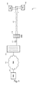
fig. 1 represents a broadband communication system making use of RPF; -
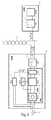
fig. 2 represents further details at the subscriber side; -
fig. 3 represents further details at the network side; and -
fig. 4 represents a plot of the RPF voltage versus time when the AC mains at the subscriber side gets unavailable. - There is seen in
fig. 1 a broadband communication system 1 comprising the following network elements: - a
DPU 100; - a Customer Premises Equipment (CPE) 200;
- a
PSE 300; - a
network unit 400; and - a
NMS 500. - The
DPU 100 is for providing broadband communication services over a copper loop plant to a plurality of subscribers. Presently, theDPU 100 is coupled to theCPE 200 and to thePSE 300 via a common Unshielded Twisted copper Pair (UTP) 610. The two wires of theUTP 610 are referred to as the TIP (T) and the RING (R) of the subscriber loop. - The
DPU 100 is further coupled to thenetwork unit 400 via one or moreoptical fibers 620, and further to theNMS 500 via a Packet Data Network (PDN) 630. - The
NMS 500 is for monitoring the operation and performance of the broadband communication system 1, and for identifying the correct causes of the various failures occurring in the broadband communication system 1. - There is seen in
fig. 2 further details at the subscriber side. - The
CPE 200 includes: - a high-pass filter 210 (or HP2) with a first cut-off frequency f1; and
- a transceiver 220 (or xTU-R) for establishing and operating a bi-directional broadband communication channel over the
subscriber loop 610. - A first pair of terminals of the high-
pass filter 210 is coupled to thesubscriber loop 610, and a second pair of terminals of the high-pass filter 210 is coupled to thetransceiver 220. - The high-
pass filter 210 is designed to let broadband communication signals BB_SIGNALS pass through, while exhibiting a high-impedance for low-frequency signals, such as a DC power feeding signal DC_SIGNAL supplied by thePSE 300. Typical values for the cut-off frequency f1 is 25kHz (xDSL over POTS), 125kHz (xDSL over ISDN), or 2MHz (G.fast). - The
PSE 300 includes: - a low-pass filter 310 (or LP2) with a second cut-off frequency f2 strictly lower than f1;
- a power feeding unit 320 (or PFU);
- a power accumulator 330 (or ACC2); and
- a detector 340 (or DET2).
- A first pair of terminals of the low-
pass filter 310 is coupled to thesubscriber loop 610, and a second pair of terminals of the low-pass filter 310 is coupled to thepower feeding unit 320. - The low-
pass filter 310 is designed to let the DC power signal DC_SIGNAL pass through, while exhibiting a high-impedance for higher frequency signals, such as the broadband communication signals BB_SIGNALS. A typical value for the cut-off frequency f2 is 200Hz (with POTS), or 3-4kHz (without POTS). - The
power feeding unit 320 is further coupled through a third pair of terminals to an AC mains 640, such as a 220Vrms or 120Vrms AC power source. - The
power feeding unit 320 is for converting the AC mains 640 into a DC voltage DC_SIGNAL, typically 57V, for remote power feeding of theDPU 100 through thesubscriber loop 610. The power feeding unit typically includes a rectifier 321 (or RECT2) for rectifying the voltage swings of the AC mains 640, a voltage regulator 322 (or REG2) for regulating the DC output voltage DC_SIGNAL to an almost-constant value, and a voltage inverter 323 (or INV) for inverting the polarity of the DC output voltage upon detection of a power outage of the AC mains 640. - The
voltage regulator 322 is further configured to generate the necessary DC voltage levels for the operation of thePSE 300. - The
voltage inverter 323 can for instance be implemented as a H-bridge, whose input is coupled to the DC output of thevoltage regulator 322, and whose output is coupled to the second pair of terminals of the low-pass filter 310. - The
power accumulator 330 is coupled to thepower feeding unit 320. More specifically, thepower accumulator 330 is coupled to the output of therectifier 321 and to thevoltage regulator 322. Thepower accumulator 330 delivers power to thevoltage regulator 322, which is designed to drain the necessary current to produce the various DC output voltages either from the AC mains 640 or from thepower accumulator 330. - The
power accumulator 330 is designed to accumulate electro-magnetic energy when the AC mains 640 is ON, and to further release that electro-magnetic energy to thevoltage regulator 322 whenever the AC mains 640 is OFF in order to sustain the operation of thevoltage regulator 322 for a short period of time, typically a few tens ms up to a few hundreds ms. - The
power accumulator 330 typically includes one or more electrolytic capacitors (or alike) coupled in parallel. Thepower accumulator 330 may further include a voltage booster for efficiently charging the capacitors. - The
detector 340 is coupled to the AC mains for power outage detection, and is configured to generate an AC_LOSS_IND signal for control of thevoltage inverter 323. when the AC_LOSS_IND signal is OFF (i.e., the AC mains is available) then the voltage inverter is in a normal state and the polarity of the DC output voltage DC_SIGNAL from thevoltage regulator 322 is left unchanged. When the AC_LOSS_IND signal is ON (i.e., the AC mains is unavailable) then the voltage inverter is in an inverted state and the polarity of the DC output voltage DC_SIGNAL from thevoltage regulator 322 is reversed. - The polarity inversion of the DC output voltage DC_SIGNAL is indicative of an imminent failure of the RPF function over the
subscriber loop 610, and is denoted as DG_SIGNAL infig. 2 and3 . - Alternatively, there can be more than one polarity inversions following some pre-defined time-pattern. In this case, more complex hardware circuitry (inc. some additional clock timing circuitry) is required and the amount of consumed power is higher.
- Also, the slope of the DC output voltage inversion shall be closely controlled in order to avoid any impulse noise that may impair the operation of neighboring equipment through electro-magnetic radiation. The right balance shall be achieved between on one hand a steep slope for almost constant RMS power, and on the other hand a smooth slope for impulse noise avoidance. In addition, the DYING GASP signal DG_SIGNAL shall go through the low-
pass filters - There is seen in
fig. 3 further details at the network side. - The
DPU 100 includes: - a high-pass filter 110 (or HP1) with the first cut-off frequency f1; and
- a transceiver 120 (or xTU-O) for establishing and operating a bi-directional broadband communication channel over the
subscriber loop 610 with thepeer transceiver 220. - A first pair of terminals of the high-
pass filter 110 is coupled to thesubscriber loop 610, and a second pair of terminals of the high-pass filter 110 is coupled to thetransceiver 120. - The high-
pass filter 110 is designed to let the broadband communication signals BB_SIGNALS pass through, while exhibiting a high-impedance for the low-frequency signals, such as the DC power feeding signal DC_SIGNAL and the DYING GASP signal DG_SIGNAL supplied by thePSE 300. - The
DPU 100 further includes: - a low-pass filter 130 (or LP1) with the second cut-off frequency f2;
- a power supply unit 140 (or PSU);
- a power accumulator 150 (or ACCL);
- a detector 160 (or DET1); and
- a NMS agent 170 (or AGT).
- A first pair of terminals of the low-
pass filter 130 is coupled to thesubscriber loop 610, and a second pair of terminals of the low-pass filter 130 is coupled to thepower supply unit 140. - The low-
pass filter 130 is designed to let the DC power feeding signal DC_SIGNAL and the DYING GASP signal DG_SIGNAL from thePSE 300 pass through, while exhibiting a high-impedance for higher frequency signals, such as the broadband communication signals BB_SIGNALS. - The
power supply unit 140 is configured to generate the necessary DC voltage levels used within the DPU 100 (e.g., 12v, 5V, 3,3v, etc) from the power feeding signals present on one or more subscriber loops. - The
power supply unit 140 typically includes a rectifier 141 (or RECT1) to accommodate for the unknown polarity of the DC power feeding signal DC_SIGNAL, and one or more voltage regulators 142 (or REG1) for regulating the one or more DC voltages levels used internally within theDPU 100. - The
power accumulator 150 is coupled to thepower supply unit 140. More specifically, thepower accumulator 150 is coupled to the output of therectifier 141 and to thevoltage regulator 142. Thevoltage regulator 142 is thus designed to drain the necessary current to produce the necessary voltage levels used internally by theDPU 100 either from the various PSEs or from theaccumulator 150. - The
power accumulator 150 is designed to accumulate electro-magnetic energy when the DPU is remotely powered by the various PSEs, and to further release that electro-magnetic energy to thevoltage regulator 142 whenever RPF is no longer available in order to sustain the operation of thevoltage regulator 142 for a short period of time, typically a few hundreds ms. - The
power accumulator 150 typically includes a bank of electrolytic capacitors coupled in parallel. Thepower accumulator 150 may further include a voltage booster for efficiently charging the capacitors. - It is noteworthy that the power consumption of the
DPU 100 scales with the number of active subscribers. When the DPU operation is only backed up by the power accumulator 150 (meaning no subscriber is active), it might be necessary to switch OFF some non-critical functions in theDPU 100 in order to save as much power as possible for DYING GASP notification towards theNMS 500. - The
detector 160 is coupled to the second pair of terminals of the low-pass filter 130, and is configured to detect the DYING GASP signal DG_SIGNAL, presently implemented as a polarity inversion of the DC power feeding signal DC_SIGNAL supplied by thePSE 300, which is indicative of an imminent failure of the RPF function over thesubscriber loop 610. - The
detector 160 may be further configured to confirm the unavailability of the RPF function by monitoring the voltage level of the DC power feeding signal DC_SIGNAL: when the DC power feeding signal DC_SIGNAL is found to be lower than a given threshold, then the RPF function is confirmed as being unavailable over thesubscriber loop 610. - Thereupon, the
detector 160 issues a RPF_LOSS_IND notification towards theNMS agent 170, possibly including an indication as per whether this is the last available RPF source. - Alternatively, the
detector 160 is configured to detect a succession of polarity inversions conforming to a pre-determined time pattern, making the detection of the DYING GASP signal more robust. Yet, there is enough robustness even with one single polarity inversion since known impairments are unlikely to induce any polarity inversion of the DC power feeding signal DC_SIGNAL. - The NMS agent is configured, upon receipt of RPF_LOSS_IND notification from the
detector 160, to encode and issue an alert message DYING_GASP_IND towards theNMS 500. The alert message DYING_GASP_IND includes the necessary pieces of information for precisely identifying the cause of the RPF failure. - An operation of the RPF function over the
subscriber loop 610 is now described with regard tofig. 4 . - On top of
fig. 4 , the AC input voltage VIN of thePSE 300 is plotted versus time. At time t1, the AC mains 640 gets unavailable. - In the middle of
fig. 4 , the output voltage VOUT of thePSE 300 is plotted versus time. At time t1+tCUT, wherein TCUT denotes some persistency timer used to confirm the AC power outage, the AC mains 640 is detected as being unavailable by thedetector 340. Consequently, the AC_LOSS_IND signal goes from OFF to ON, which commands thevoltage inverter 323 to reverse the polarity of the output voltage VOUT. The output voltage VOUT then goes from VNOM to -VNOM, wherein VNOM denotes the nominal voltage value used for RPF (typically 57V). At time t2, the voltage supplied by thepower accumulator 330 is no longer sufficient to sustain the nominal voltage value VNOM, and the output voltage VOUT starts decreasing down to zero at time t3. - In the bottom of
fig. 4 , the output voltage VOUT of thePSE 300 is plotted versus time. In this embodiment, more than one polarity inversion evenly-spaced across time is used for notifying the imminent failure of the RPF function. As one can notice, the amplitude starts decreasing from time t2 onwards. - It is to be noticed that the term 'comprising' should not be interpreted as being restricted to the means listed thereafter. Thus, the scope of the expression 'a device comprising means A and B' should not be limited to devices consisting only of components A and B. It means that with respect to the present invention, the relevant components of the device are A and B.
- It is to be further noticed that the term 'coupled' should not be interpreted as being restricted to direct connections only. Thus, the scope of the expression 'a device A coupled to a device B' should not be limited to devices or systems wherein an output of device A is directly connected to an input of device B, and/or vice-versa. It means that there exists a path between an output of A and an input of B, and/or vice-versa, which may be a path including other devices or means.
- The description and drawings merely illustrate the principles of the invention. It will thus be appreciated that those skilled in the art will be able to devise various arrangements that, although not explicitly described or shown herein, embody the principles of the invention. Furthermore, all examples recited herein are principally intended expressly to be only for pedagogical purposes to aid the reader in understanding the principles of the invention and the concepts contributed by the inventor(s) to furthering the art, and are to be construed as being without limitation to such specifically recited examples and conditions. Moreover, all statements herein reciting principles, aspects, and embodiments of the invention, as well as specific examples thereof, are intended to encompass equivalents thereof.
- The functions of the various elements shown in the figures may be provided through the use of dedicated hardware as well as hardware capable of executing software in association with appropriate software. When provided by a processor, the functions may be provided by a single dedicated processor, by a single shared processor, or by a plurality of individual processors, some of which may be shared. Moreover, a processor should not be construed to refer exclusively to hardware capable of executing software, and may implicitly include, without limitation, Digital Signal Processor (DSP) hardware, network processor, Application Specific Integrated Circuit (ASIC), Field Programmable Gate Array (FPGA), etc. Other hardware, conventional and/or custom, such as Read Only Memory (ROM), Random Access Memory (RAM), and non volatile storage, may also be included.
Claims (15)
- A power sourcing equipment (300) comprising a power injector (320) configured to generate a power feeding signal (DC_SIGNAL) from a power source (640) for remote power feeding of an access node (100) through a subscriber loop (610), wherein the power sourcing equipment further comprises a detector (340) configured to detect a power outage of the power source,
and wherein the power injector is further configured, upon detection of the power outage, to generate an imminent failure indication signal (DG_SIGNAL) by at least one polarity inversion of the power feeding signal for further detection by the access node. - A power sourcing equipment (300) according to claim 1, wherein the at least one polarity inversion of the power feeding signal comprises a single polarity inversion.
- A power sourcing equipment (300) according to claim 1, wherein the at least one polarity inversion of the power feeding signal comprises two or more polarity inversions conforming to a pre-determined time pattern.
- A power sourcing equipment (300) according to claim 2 or 3, wherein the at least one polarity inversion has a controlled slope.
- A power sourcing equipment (300) according to claim 1, wherein the power injector is further configured to issue the imminent failure indication signal after the power outage persists beyond a given period of time (tCUT).
- A power sourcing equipment (300) according to claim 1, wherein the power sourcing equipment further comprises a power accumulator (330) configured to deliver power to the power injector during the power outage for generation of the imminent failure indication signal.
- A power sourcing equipment (300) according to claim 6, wherein the power accumulator comprises one or more capacitors.
- A power sourcing equipment (300) according to claim 1, wherein the imminent failure indication signal is for notification of the imminent unavailability of the power feeding signal to the access node.
- A power sourcing equipment (300) according to claim 1, wherein the power feeding signal is a DC signal (DC_SIGNAL).
- A power sourcing equipment (300) according to claim 9, wherein the power sourcing equipment further comprises a low pass filter (310) for frequency-multiplexing the power feeding signal with a Discrete Multi-Tone DMT communication signal (BB_SIGNALS) over the subscriber loop.
- A customer premises equipment (200) comprising a power sourcing equipment (300) according to any of the preceding claims.
- An access node (100) for providing communication services to subscribers over a plurality of subscriber loops, and comprising:- a power extractor (140) for extracting power from a power feeding signal (DC_SIGNAL) present over a subscriber loop (610) of the plurality of the subscriber loops for power feeding of the access node,- a detector (160) configured to detect at least one polarity inversion of the power feeding signal,- a signaling means (170) coupled to the detector, and configured, upon detection of the at least one polarity inversion of the power feeding signal, to issue an alert message (DYING_GASP_IND) to a network manager (500).
- An access node (100) according to claim 12, wherein the signaling means is further configured to issue the alert message only in the event of no other power feeding signal being available on another subscriber loop.
- An access node (100) according to claim 12, wherein the access node further comprises a power accumulator (150) configured to deliver power to the power extractor to accommodate the at least one polarity inversion.
- An access node (100) according to any of claims 12 to 14, wherein the access node is a Distribution Point Unit DPU (100).
Priority Applications (1)
| Application Number | Priority Date | Filing Date | Title |
|---|---|---|---|
| EP15305652.8A EP3089438B1 (en) | 2015-04-28 | 2015-04-28 | Imminent failure indication for power sourcing equipment |
Applications Claiming Priority (1)
| Application Number | Priority Date | Filing Date | Title |
|---|---|---|---|
| EP15305652.8A EP3089438B1 (en) | 2015-04-28 | 2015-04-28 | Imminent failure indication for power sourcing equipment |
Publications (2)
| Publication Number | Publication Date |
|---|---|
| EP3089438A1 true EP3089438A1 (en) | 2016-11-02 |
| EP3089438B1 EP3089438B1 (en) | 2017-10-18 |
Family
ID=53040487
Family Applications (1)
| Application Number | Title | Priority Date | Filing Date |
|---|---|---|---|
| EP15305652.8A Not-in-force EP3089438B1 (en) | 2015-04-28 | 2015-04-28 | Imminent failure indication for power sourcing equipment |
Country Status (1)
| Country | Link |
|---|---|
| EP (1) | EP3089438B1 (en) |
Cited By (3)
| Publication number | Priority date | Publication date | Assignee | Title |
|---|---|---|---|---|
| JP2018191211A (en) * | 2017-05-10 | 2018-11-29 | 住友電気工業株式会社 | G. fast communication system, G.G. fast aggregation device, G.M. fast in-home device, and G. Fast communication method |
| CN109005041A (en) * | 2017-06-07 | 2018-12-14 | 中兴通讯股份有限公司 | Local side equipment, reverse power supply system and method |
| US20190132139A1 (en) * | 2015-05-26 | 2019-05-02 | Alcatel Lucent | Provisioning of new broadband communication services using reverse power feeding |
Families Citing this family (1)
| Publication number | Priority date | Publication date | Assignee | Title |
|---|---|---|---|---|
| US10951056B2 (en) | 2018-03-07 | 2021-03-16 | At&T Intellectual Property I, L.P. | Systems and methods for intelligent power distribution |
Citations (3)
| Publication number | Priority date | Publication date | Assignee | Title |
|---|---|---|---|---|
| WO2006044783A2 (en) * | 2004-10-15 | 2006-04-27 | Terabeam Wireless | System and method of polarity reversal for reload detection |
| US20100215359A1 (en) * | 2009-02-22 | 2010-08-26 | Wen Li | Smart optical transceiver having integrated optical dying gasp function |
| US20140314412A1 (en) * | 2005-03-01 | 2014-10-23 | Alexander I. Soto | System and method for a subscriber-powered network element |
-
2015
- 2015-04-28 EP EP15305652.8A patent/EP3089438B1/en not_active Not-in-force
Patent Citations (3)
| Publication number | Priority date | Publication date | Assignee | Title |
|---|---|---|---|---|
| WO2006044783A2 (en) * | 2004-10-15 | 2006-04-27 | Terabeam Wireless | System and method of polarity reversal for reload detection |
| US20140314412A1 (en) * | 2005-03-01 | 2014-10-23 | Alexander I. Soto | System and method for a subscriber-powered network element |
| US20100215359A1 (en) * | 2009-02-22 | 2010-08-26 | Wen Li | Smart optical transceiver having integrated optical dying gasp function |
Cited By (5)
| Publication number | Priority date | Publication date | Assignee | Title |
|---|---|---|---|---|
| US20190132139A1 (en) * | 2015-05-26 | 2019-05-02 | Alcatel Lucent | Provisioning of new broadband communication services using reverse power feeding |
| US10476685B2 (en) * | 2015-05-26 | 2019-11-12 | Alcatel Lucent | Provisioning of new broadband communication services using reverse power feeding |
| JP2018191211A (en) * | 2017-05-10 | 2018-11-29 | 住友電気工業株式会社 | G. fast communication system, G.G. fast aggregation device, G.M. fast in-home device, and G. Fast communication method |
| CN109005041A (en) * | 2017-06-07 | 2018-12-14 | 中兴通讯股份有限公司 | Local side equipment, reverse power supply system and method |
| EP3637676A4 (en) * | 2017-06-07 | 2021-03-10 | ZTE Corporation | CENTRAL OFFICE EQUIPMENT, AND REVERSE POWER SUPPLY PROCESS AND SYSTEM |
Also Published As
| Publication number | Publication date |
|---|---|
| EP3089438B1 (en) | 2017-10-18 |
Similar Documents
| Publication | Publication Date | Title |
|---|---|---|
| EP3089438B1 (en) | Imminent failure indication for power sourcing equipment | |
| CN1833360B (en) | Circuit and method for injecting power signal onto communication line | |
| EP3099005B1 (en) | Provisioning of new broadband communication services using reverse power feeding | |
| US9628283B2 (en) | Reverse powering system for telecommunications node | |
| CN105027380B (en) | Accumulating system, monitoring arrangement, electric control system | |
| KR101742417B1 (en) | Method for dealing with anomalous conditions in a reverse power network, and power injector for use in such a method | |
| US9614976B2 (en) | Systems and methods for powering network access devices from customer premises equipment | |
| JPWO2010131305A1 (en) | Power line communication apparatus and power line communication system | |
| CN1833262B (en) | Input voltage sense circuit in a line powered network element | |
| JP3686863B2 (en) | Uninterruptible power system | |
| AU3053299A (en) | Dsl modem | |
| CN110048859A (en) | A kind of POE method of supplying power to, equipment and storage medium | |
| US20070127712A1 (en) | Methods and apparatuses to provide a back up power supply for a network interface device | |
| US20100080380A1 (en) | Method and Apparatus for Supplying DC Feed to a Subscriber Line | |
| US20070003053A1 (en) | System and device for the remote powering of a data-processing device | |
| TWI587123B (en) | Network camera system and network camera thereof | |
| EP2053778A1 (en) | Method and system for remote power feeding of a DSL communication device | |
| JP3832010B2 (en) | Residential line termination circuit | |
| EP3057199A1 (en) | Power supply system | |
| EP3316564B1 (en) | Power-efficient decoding arrangement for rpf operation | |
| US4653046A (en) | Single channel subscriber carrier system | |
| JP2003046590A (en) | Signal processing method and its device | |
| CN108429622B (en) | A reverse power supply method and device | |
| JP2014183374A (en) | Communication device and communication device control method | |
| JP2001057587A (en) | In-band signal equipment |
Legal Events
| Date | Code | Title | Description |
|---|---|---|---|
| PUAI | Public reference made under article 153(3) epc to a published international application that has entered the european phase |
Free format text: ORIGINAL CODE: 0009012 |
|
| AK | Designated contracting states |
Kind code of ref document: A1 Designated state(s): AL AT BE BG CH CY CZ DE DK EE ES FI FR GB GR HR HU IE IS IT LI LT LU LV MC MK MT NL NO PL PT RO RS SE SI SK SM TR |
|
| AX | Request for extension of the european patent |
Extension state: BA ME |
|
| GRAP | Despatch of communication of intention to grant a patent |
Free format text: ORIGINAL CODE: EPIDOSNIGR1 |
|
| 17P | Request for examination filed |
Effective date: 20170502 |
|
| RBV | Designated contracting states (corrected) |
Designated state(s): AL AT BE BG CH CY CZ DE DK EE ES FI FR GB GR HR HU IE IS IT LI LT LU LV MC MK MT NL NO PL PT RO RS SE SI SK SM TR |
|
| RIC1 | Information provided on ipc code assigned before grant |
Ipc: H04M 19/08 20060101AFI20170515BHEP |
|
| INTG | Intention to grant announced |
Effective date: 20170531 |
|
| GRAS | Grant fee paid |
Free format text: ORIGINAL CODE: EPIDOSNIGR3 |
|
| GRAA | (expected) grant |
Free format text: ORIGINAL CODE: 0009210 |
|
| AK | Designated contracting states |
Kind code of ref document: B1 Designated state(s): AL AT BE BG CH CY CZ DE DK EE ES FI FR GB GR HR HU IE IS IT LI LT LU LV MC MK MT NL NO PL PT RO RS SE SI SK SM TR |
|
| REG | Reference to a national code |
Ref country code: GB Ref legal event code: FG4D |
|
| REG | Reference to a national code |
Ref country code: CH Ref legal event code: EP |
|
| REG | Reference to a national code |
Ref country code: AT Ref legal event code: REF Ref document number: 938864 Country of ref document: AT Kind code of ref document: T Effective date: 20171115 Ref country code: IE Ref legal event code: FG4D |
|
| REG | Reference to a national code |
Ref country code: DE Ref legal event code: R096 Ref document number: 602015005446 Country of ref document: DE |
|
| REG | Reference to a national code |
Ref country code: NL Ref legal event code: MP Effective date: 20171018 |
|
| REG | Reference to a national code |
Ref country code: LT Ref legal event code: MG4D |
|
| REG | Reference to a national code |
Ref country code: AT Ref legal event code: MK05 Ref document number: 938864 Country of ref document: AT Kind code of ref document: T Effective date: 20171018 |
|
| REG | Reference to a national code |
Ref country code: CH Ref legal event code: PCOW Free format text: NEW ADDRESS: SITE NOKIA PARIS SACLAY ROUTE DE VILLEJUST, 91620 NOZAY (FR) |
|
| PG25 | Lapsed in a contracting state [announced via postgrant information from national office to epo] |
Ref country code: NL Free format text: LAPSE BECAUSE OF FAILURE TO SUBMIT A TRANSLATION OF THE DESCRIPTION OR TO PAY THE FEE WITHIN THE PRESCRIBED TIME-LIMIT Effective date: 20171018 |
|
| RAP2 | Party data changed (patent owner data changed or rights of a patent transferred) |
Owner name: ALCATEL LUCENT |
|
| REG | Reference to a national code |
Ref country code: FR Ref legal event code: PLFP Year of fee payment: 4 |
|
| PG25 | Lapsed in a contracting state [announced via postgrant information from national office to epo] |
Ref country code: ES Free format text: LAPSE BECAUSE OF FAILURE TO SUBMIT A TRANSLATION OF THE DESCRIPTION OR TO PAY THE FEE WITHIN THE PRESCRIBED TIME-LIMIT Effective date: 20171018 Ref country code: NO Free format text: LAPSE BECAUSE OF FAILURE TO SUBMIT A TRANSLATION OF THE DESCRIPTION OR TO PAY THE FEE WITHIN THE PRESCRIBED TIME-LIMIT Effective date: 20180118 Ref country code: LT Free format text: LAPSE BECAUSE OF FAILURE TO SUBMIT A TRANSLATION OF THE DESCRIPTION OR TO PAY THE FEE WITHIN THE PRESCRIBED TIME-LIMIT Effective date: 20171018 Ref country code: FI Free format text: LAPSE BECAUSE OF FAILURE TO SUBMIT A TRANSLATION OF THE DESCRIPTION OR TO PAY THE FEE WITHIN THE PRESCRIBED TIME-LIMIT Effective date: 20171018 Ref country code: SE Free format text: LAPSE BECAUSE OF FAILURE TO SUBMIT A TRANSLATION OF THE DESCRIPTION OR TO PAY THE FEE WITHIN THE PRESCRIBED TIME-LIMIT Effective date: 20171018 |
|
| PG25 | Lapsed in a contracting state [announced via postgrant information from national office to epo] |
Ref country code: IS Free format text: LAPSE BECAUSE OF FAILURE TO SUBMIT A TRANSLATION OF THE DESCRIPTION OR TO PAY THE FEE WITHIN THE PRESCRIBED TIME-LIMIT Effective date: 20180218 Ref country code: LV Free format text: LAPSE BECAUSE OF FAILURE TO SUBMIT A TRANSLATION OF THE DESCRIPTION OR TO PAY THE FEE WITHIN THE PRESCRIBED TIME-LIMIT Effective date: 20171018 Ref country code: GR Free format text: LAPSE BECAUSE OF FAILURE TO SUBMIT A TRANSLATION OF THE DESCRIPTION OR TO PAY THE FEE WITHIN THE PRESCRIBED TIME-LIMIT Effective date: 20180119 Ref country code: BG Free format text: LAPSE BECAUSE OF FAILURE TO SUBMIT A TRANSLATION OF THE DESCRIPTION OR TO PAY THE FEE WITHIN THE PRESCRIBED TIME-LIMIT Effective date: 20180118 Ref country code: RS Free format text: LAPSE BECAUSE OF FAILURE TO SUBMIT A TRANSLATION OF THE DESCRIPTION OR TO PAY THE FEE WITHIN THE PRESCRIBED TIME-LIMIT Effective date: 20171018 Ref country code: HR Free format text: LAPSE BECAUSE OF FAILURE TO SUBMIT A TRANSLATION OF THE DESCRIPTION OR TO PAY THE FEE WITHIN THE PRESCRIBED TIME-LIMIT Effective date: 20171018 Ref country code: AT Free format text: LAPSE BECAUSE OF FAILURE TO SUBMIT A TRANSLATION OF THE DESCRIPTION OR TO PAY THE FEE WITHIN THE PRESCRIBED TIME-LIMIT Effective date: 20171018 |
|
| REG | Reference to a national code |
Ref country code: DE Ref legal event code: R097 Ref document number: 602015005446 Country of ref document: DE |
|
| PG25 | Lapsed in a contracting state [announced via postgrant information from national office to epo] |
Ref country code: CZ Free format text: LAPSE BECAUSE OF FAILURE TO SUBMIT A TRANSLATION OF THE DESCRIPTION OR TO PAY THE FEE WITHIN THE PRESCRIBED TIME-LIMIT Effective date: 20171018 Ref country code: SK Free format text: LAPSE BECAUSE OF FAILURE TO SUBMIT A TRANSLATION OF THE DESCRIPTION OR TO PAY THE FEE WITHIN THE PRESCRIBED TIME-LIMIT Effective date: 20171018 Ref country code: DK Free format text: LAPSE BECAUSE OF FAILURE TO SUBMIT A TRANSLATION OF THE DESCRIPTION OR TO PAY THE FEE WITHIN THE PRESCRIBED TIME-LIMIT Effective date: 20171018 Ref country code: EE Free format text: LAPSE BECAUSE OF FAILURE TO SUBMIT A TRANSLATION OF THE DESCRIPTION OR TO PAY THE FEE WITHIN THE PRESCRIBED TIME-LIMIT Effective date: 20171018 |
|
| PLBE | No opposition filed within time limit |
Free format text: ORIGINAL CODE: 0009261 |
|
| STAA | Information on the status of an ep patent application or granted ep patent |
Free format text: STATUS: NO OPPOSITION FILED WITHIN TIME LIMIT |
|
| PG25 | Lapsed in a contracting state [announced via postgrant information from national office to epo] |
Ref country code: RO Free format text: LAPSE BECAUSE OF FAILURE TO SUBMIT A TRANSLATION OF THE DESCRIPTION OR TO PAY THE FEE WITHIN THE PRESCRIBED TIME-LIMIT Effective date: 20171018 Ref country code: PL Free format text: LAPSE BECAUSE OF FAILURE TO SUBMIT A TRANSLATION OF THE DESCRIPTION OR TO PAY THE FEE WITHIN THE PRESCRIBED TIME-LIMIT Effective date: 20171018 Ref country code: IT Free format text: LAPSE BECAUSE OF FAILURE TO SUBMIT A TRANSLATION OF THE DESCRIPTION OR TO PAY THE FEE WITHIN THE PRESCRIBED TIME-LIMIT Effective date: 20171018 Ref country code: SM Free format text: LAPSE BECAUSE OF FAILURE TO SUBMIT A TRANSLATION OF THE DESCRIPTION OR TO PAY THE FEE WITHIN THE PRESCRIBED TIME-LIMIT Effective date: 20171018 |
|
| 26N | No opposition filed |
Effective date: 20180719 |
|
| PG25 | Lapsed in a contracting state [announced via postgrant information from national office to epo] |
Ref country code: MC Free format text: LAPSE BECAUSE OF FAILURE TO SUBMIT A TRANSLATION OF THE DESCRIPTION OR TO PAY THE FEE WITHIN THE PRESCRIBED TIME-LIMIT Effective date: 20171018 Ref country code: SI Free format text: LAPSE BECAUSE OF FAILURE TO SUBMIT A TRANSLATION OF THE DESCRIPTION OR TO PAY THE FEE WITHIN THE PRESCRIBED TIME-LIMIT Effective date: 20171018 |
|
| REG | Reference to a national code |
Ref country code: CH Ref legal event code: PL |
|
| REG | Reference to a national code |
Ref country code: BE Ref legal event code: MM Effective date: 20180430 |
|
| REG | Reference to a national code |
Ref country code: IE Ref legal event code: MM4A |
|
| PG25 | Lapsed in a contracting state [announced via postgrant information from national office to epo] |
Ref country code: LU Free format text: LAPSE BECAUSE OF NON-PAYMENT OF DUE FEES Effective date: 20180428 |
|
| PG25 | Lapsed in a contracting state [announced via postgrant information from national office to epo] |
Ref country code: LI Free format text: LAPSE BECAUSE OF NON-PAYMENT OF DUE FEES Effective date: 20180430 Ref country code: CH Free format text: LAPSE BECAUSE OF NON-PAYMENT OF DUE FEES Effective date: 20180430 Ref country code: BE Free format text: LAPSE BECAUSE OF NON-PAYMENT OF DUE FEES Effective date: 20180430 |
|
| PG25 | Lapsed in a contracting state [announced via postgrant information from national office to epo] |
Ref country code: IE Free format text: LAPSE BECAUSE OF NON-PAYMENT OF DUE FEES Effective date: 20180428 |
|
| PGFP | Annual fee paid to national office [announced via postgrant information from national office to epo] |
Ref country code: FR Payment date: 20190313 Year of fee payment: 5 |
|
| PGFP | Annual fee paid to national office [announced via postgrant information from national office to epo] |
Ref country code: DE Payment date: 20190416 Year of fee payment: 5 |
|
| PGFP | Annual fee paid to national office [announced via postgrant information from national office to epo] |
Ref country code: GB Payment date: 20190424 Year of fee payment: 5 |
|
| PG25 | Lapsed in a contracting state [announced via postgrant information from national office to epo] |
Ref country code: MT Free format text: LAPSE BECAUSE OF NON-PAYMENT OF DUE FEES Effective date: 20180428 |
|
| PG25 | Lapsed in a contracting state [announced via postgrant information from national office to epo] |
Ref country code: TR Free format text: LAPSE BECAUSE OF FAILURE TO SUBMIT A TRANSLATION OF THE DESCRIPTION OR TO PAY THE FEE WITHIN THE PRESCRIBED TIME-LIMIT Effective date: 20171018 |
|
| PG25 | Lapsed in a contracting state [announced via postgrant information from national office to epo] |
Ref country code: PT Free format text: LAPSE BECAUSE OF FAILURE TO SUBMIT A TRANSLATION OF THE DESCRIPTION OR TO PAY THE FEE WITHIN THE PRESCRIBED TIME-LIMIT Effective date: 20171018 |
|
| PG25 | Lapsed in a contracting state [announced via postgrant information from national office to epo] |
Ref country code: HU Free format text: LAPSE BECAUSE OF FAILURE TO SUBMIT A TRANSLATION OF THE DESCRIPTION OR TO PAY THE FEE WITHIN THE PRESCRIBED TIME-LIMIT; INVALID AB INITIO Effective date: 20150428 Ref country code: CY Free format text: LAPSE BECAUSE OF FAILURE TO SUBMIT A TRANSLATION OF THE DESCRIPTION OR TO PAY THE FEE WITHIN THE PRESCRIBED TIME-LIMIT Effective date: 20171018 Ref country code: MK Free format text: LAPSE BECAUSE OF NON-PAYMENT OF DUE FEES Effective date: 20171018 |
|
| PG25 | Lapsed in a contracting state [announced via postgrant information from national office to epo] |
Ref country code: AL Free format text: LAPSE BECAUSE OF FAILURE TO SUBMIT A TRANSLATION OF THE DESCRIPTION OR TO PAY THE FEE WITHIN THE PRESCRIBED TIME-LIMIT Effective date: 20171018 |
|
| REG | Reference to a national code |
Ref country code: DE Ref legal event code: R119 Ref document number: 602015005446 Country of ref document: DE |
|
| PG25 | Lapsed in a contracting state [announced via postgrant information from national office to epo] |
Ref country code: FR Free format text: LAPSE BECAUSE OF NON-PAYMENT OF DUE FEES Effective date: 20200430 Ref country code: DE Free format text: LAPSE BECAUSE OF NON-PAYMENT OF DUE FEES Effective date: 20201103 |
|
| GBPC | Gb: european patent ceased through non-payment of renewal fee |
Effective date: 20200428 |
|
| PG25 | Lapsed in a contracting state [announced via postgrant information from national office to epo] |
Ref country code: GB Free format text: LAPSE BECAUSE OF NON-PAYMENT OF DUE FEES Effective date: 20200428 |